THE STOVE DOES NOT WORK IF THE LID OF THE PELLET HOPPER IS OPEN.
04.7 AIR-TIGHT STOVES
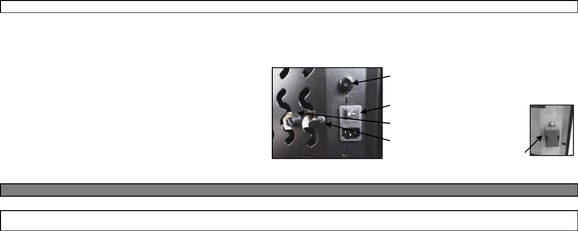
(Electronics p. 26)
IMPORTANT: THE LENGTH OF THE FLUE DUCT MUST BE OF MAX. 6 METERS WITH A DIAMETER OF 80 mm; EVERY 90° CURVE OR (T) CONNECTION
IS CONSIDERED AS 1 METER OF PIPE.
Although really thin (only 25 cm deep), this pellet stove ensures high
performance in terms of heat output thanks to its air-tight structure that
facilitates heat development and renders it suitable for heating up closed
environments such as bedrooms, studios and bathrooms. It comes with
glass door cleaner, remote control system with room temperature sensor
that can manage up to 10 operating powers and DFSC (Dynamic Flow
Control System).
A stove that heats up and enhances the design of the rooms thanks to its
modern lines, rounded edges and door made entirely of screen-printed
glass.
THE STOVE DOES NOT WORK IF THE LID OF THE PELLET HOPPER
IS OPEN
05. PRODUCT USE
05.1 ELECTRONICS WITH 6-BUTTON LED DISPLAY p. 3 F-1
(Pellet inserts – Canalized pellet stove)
PROPER FUNCTIONING AND CONTROL ADJUSTMENT DEVICES
First connect the stove plug to the mains and load the pellet hopper. Be careful not to empty the entire bag at once. Perform this operation slowly.
DESCRIPTION OF PANEL
BUTTON (P1) - Temperature increase:
When in (SET TEMP) mode, use this button to increase the thermostat value from a minimum of 6° C to a maximum of 41° C. The selected value appears on
the lower display, while the upper display shows the message SET. When modifying user and technician parameters, use this button to increase the parameter
value. The selected value appears on the lower display. When in working mode, use this button to visualise the fume temperature on the lower display.
BUTTON (P2) - Temperature decrease:
When in (SET TEMP) mode, use this button to decrease the thermostat value from a maximum of 41° C to a minimum of 06° C. The selected value appears on
the lower display, while the upper display shows the message SET.
When modifying user and technician parameters, use this button to decrease the parameter value. The selected value appears on the lower display. When in
working mode, use this button to visualise the time on the lower display.
BUTTON (P3) - Set/menu:
Use this button to access (SET TEMP) temperature setting and user and technician parameter menu. Press P3 button repeatedly to cycle through all the
parameters inside the menu. The upper display visualises the parameter label, while the lower display shows the relevant value.
BUTTON (P4) - ON/OFF Release:
Hold this button down for two seconds to manually switch the stove on or off respectively depending on its initial status (switched ON or OFF).
Should have any alarm blocked the stove, press this button to unlock it and subsequently switch it OFF.
When setting user/technician parameters, use this button to exit the menu at any setting step.
BUTTON (P5) - Heat output decrease:
When in working mode (ON), use this button to decrease the heat output from 5, maximum value, to 1. The selected value appears on the upper display.
BUTTON (P6) - Heat output increase:
When in working mode (ON), use this button to increase the heat output from 1, minimum value, to 5. The selected value appears on the upper display.
ECO – Temperature reached: When the required temperature is reached, the message ECO appears on the display. P5 and P6 buttons are disabled
automatically. Change the set temperature to enable P5 and P6 buttons again and access the heat output setting.
ACRIVE CHRONO LED (L1):
The LED is on when UT1 user parameter is different from OFF in the menu and weekly programming or lap time can be set.
AUGER TUBE ON LED (L2):
The LED is on whenever the Auger tube is enabled and the motor, feeding the pellets in the combustion chamber, is working. This occurs during start-up and
working mode.
REMOTE CONTROL RECEIVER LED (L3):
The LED flashes whenever the control panel receives a signal from the IR remote control to modify temperature/heat output.
ROOM THERMOSTAT LED (L4):
The LED is on whenever the room temperature is higher than the set temperature (external thermostat not in use). When using the external thermostat (if
available), the LED is lit when the thermostat temperature is reached.
TEMPERATURE SETTING LED (L5):
The LED flashes when working in the user/technician menu or while setting the temperature (SET TEMP).
During working mode, it shows the heat output set by the user.
When modifying user/technician parameters, it shows the label of the parameter in question.
DISPLAY Status/Time/Temperature/Parameter value DISPLAY (D2):
It shows the board status during start-up phase.
During working mode, it shows the temperature set by the user.
When modifying user/technician parameters, it shows the value of the parameter in question.
USER FUNCRIONS
Stove ignition
Hold down P4 for a few seconds to switch on the stove. The display shows that the stove is on. The stove goes into the pre-ventilation/pre-heating phase for 90
seconds. The stove enters the pre-load mode for the period of time indicated by Pr45 parameter. Meanwhile, the Auger tube rotates and continues to load pellets.
At the end of the period of time set by Pr45 parameter, the system goes into the waiting phase whose duration is defined by Pr46 parameter. Then the loading
phase begins at the speed set by Pr04 parameter. The Auger tube ON LED is on indicating that the Auger tube is working. The ignition plug switches off when
fume temperature exceeds value under parameter Pr13, increasing by a gradient of approx. 3 C°/ minute.
Pellet manual loading
Press P5 and P6 buttons simultaneously to load the pellets. This function is available only when the stove is switched off and cold.
Libble takes abuse of its services very seriously. We're committed to dealing with such abuse according to the laws in your country of residence. When you submit a report, we'll investigate it and take the appropriate action. We'll get back to you only if we require additional details or have more information to share.
Product:
Forumrules
To achieve meaningful questions, we apply the following rules:
First, read the manual;
Check if your question has been asked previously;
Try to ask your question as clearly as possible;
Did you already try to solve the problem? Please mention this;
Is your problem solved by a visitor then let him/her know in this forum;
To give a response to a question or answer, do not use this form but click on the button 'reply to this question';
Your question will be posted here and emailed to our subscribers. Therefore, avoid filling in personal details.
Register
Register getting emails for Eva Calor Erika at:
new questions and answers
new manuals
You will receive an email to register for one or both of the options.
Get your user manual by e-mail
Enter your email address to receive the manual of Eva Calor Erika in the language / languages: English as an attachment in your email.
The manual is 5,83 mb in size.
You will receive the manual in your email within minutes. If you have not received an email, then probably have entered the wrong email address or your mailbox is too full. In addition, it may be that your ISP may have a maximum size for emails to receive.
If you have not received an email with the manual within fifteen minutes, it may be that you have a entered a wrong email address or that your ISP has set a maximum size to receive email that is smaller than the size of the manual.
The email address you have provided is not correct.
Please check the email address and correct it.
Your question is posted on this page
Would you like to receive an email when new answers and questions are posted? Please enter your email address.