The same applies to UT11 - UT12 - UT13 - UT14 - UT15 - UT16.
Example: TIMER PROGRAMMING
UT01 --- CURRENT DAY SETTING (DAY 7 = SUNDAY)
PROGRAMME1
UT05 --- 1ST SWITCHING ON ( e.g. 07:00am)
UT06 --- 1ST SWITCHING OFF TIME ( e.g. 09:00am)
UT07 --- DAY CONFIRMATION ( e.g. DAY 1 -OFF / DAY2-OFF/DAY3-OFF/DAY4-OFF/DAY5-OFF/DAY6-ON/DAY7-ON)
PROGRAMME 2
UT08 --- 2ND SWITCHING ON ( e.g. 06:00pm)
UT09 --- 2ND SWITCHING OFF TIME ( e.g. 12:00am)
UT10 --- DAY CONFIRMATION ( e.g. DAY 1 -ON / DAY2-ON/DAY3-ON/DAY4-ON/DAY5-ON/DAY6-OFF/DAY7-OFF)
DUCTING SYSTEM
Fan no. 2 speed setting
To set the speed of the second exchanger, press P3 (SET) button and then P6 repeatedly to select the desired value.
ALARMS
The board is fitted with a control system that shows on the display where the failure occurred to inform the user in case of malfunctioning. Press P4 button to
CLEAR the message on the display.
The meaning of these alarm messages is explained in detail below.
ALAR SOND FUMI - Fume temperature sensor alarm
The alarm is triggered when the fume temperature sensor is damaged or disconnected. The exhaust and exchanger blower speed is increased to its maximum
value and the Auger motor is switched off, interrupting pellet loading. The blower remains on for approximately 10 minutes.
ALAR HOT TEMP - Fume overtemperature alarm
The alarm is triggered whenever the fume sensor detects a temperature exceeding 220°C. The message ALAR HOT TEMP appears on the display. The exhaust
blower speed is increased to its maximum value and the Auger tube motor is switched off, interrupting pellet loading. The blower remains on for approximately 10
minutes.
ALAR NO ACC - Ignition failure alarm
This check alarm when the stove temperature does not rise more than 3°C/ minuto. The message ALAR NO ACC appears on the display. The stove enters the
switching off phase which is completed in approximately 10 minutes, as with the other alarms described above.
ALAR COOL FIRE - Stove switching-off during working mode alarm
The alarm is triggered when the flame goes out and the fume temperature falls below the stove minimum working threshold. The message ALAR NO FIRE
appears on the display and the stove switches off.
ALAR DEP FAIL - Negative pressure alarm
The alarm is triggered when the chimney or the fume outlet are clogged (ALAR DEP FAIL)
ALAR SIC FAIL - General safety thermostat alarm
If the general safety thermostat detects a value exceeding the trigger threshold, it immediately switches off the Auger tube (to which it is
connected in series), while the control board acquires this change in status through the AL1 clamp in CN4. The message ALAR SIC FAIL
is displayed. Unscrew the black cap on the back of the stove and press the button to reset the contact.
ALAR COOL FIRE - No electrical supply alarm
The lack of electrical supply during the work, stops the functioning of electrical components of the stove. When the electrical supply is restored the stove shows
the alarm “ALAR COOL FIRE” and it is necessary to switch on again, after waiting for a cooling period,COOL FIRE, till when the smoke temperature goes below
the limit temperature set at parameter Pr13.
ALAR FAN FAIL - Damage exhaust blower alarm
In case the exhaust blower (smoke fan) gets broken, the stove switches off and it is displayed the message ALAR FAN FAIL.
05.2 ELECTRONICS WITH 6-BUTTON LCD DISPLAY p. 3 F-2 F-3
(Pellet stoves)
PROPER FUNCTIONING AND CONTROL ADJUSTMENT DEVICES
Control panel
The control panel shows the information concerning the stove status. Several types of data can be displayed and the settings available according to the access
level can be modified by entering the menu.
Depending on the selected mode and on their position on the display, the data visualised may acquire different meanings.
DESCRIPTION OF PANEL
P. 3 F-2
(A1) TIME CLOCK
(A2) ROOM TEMPERATURE
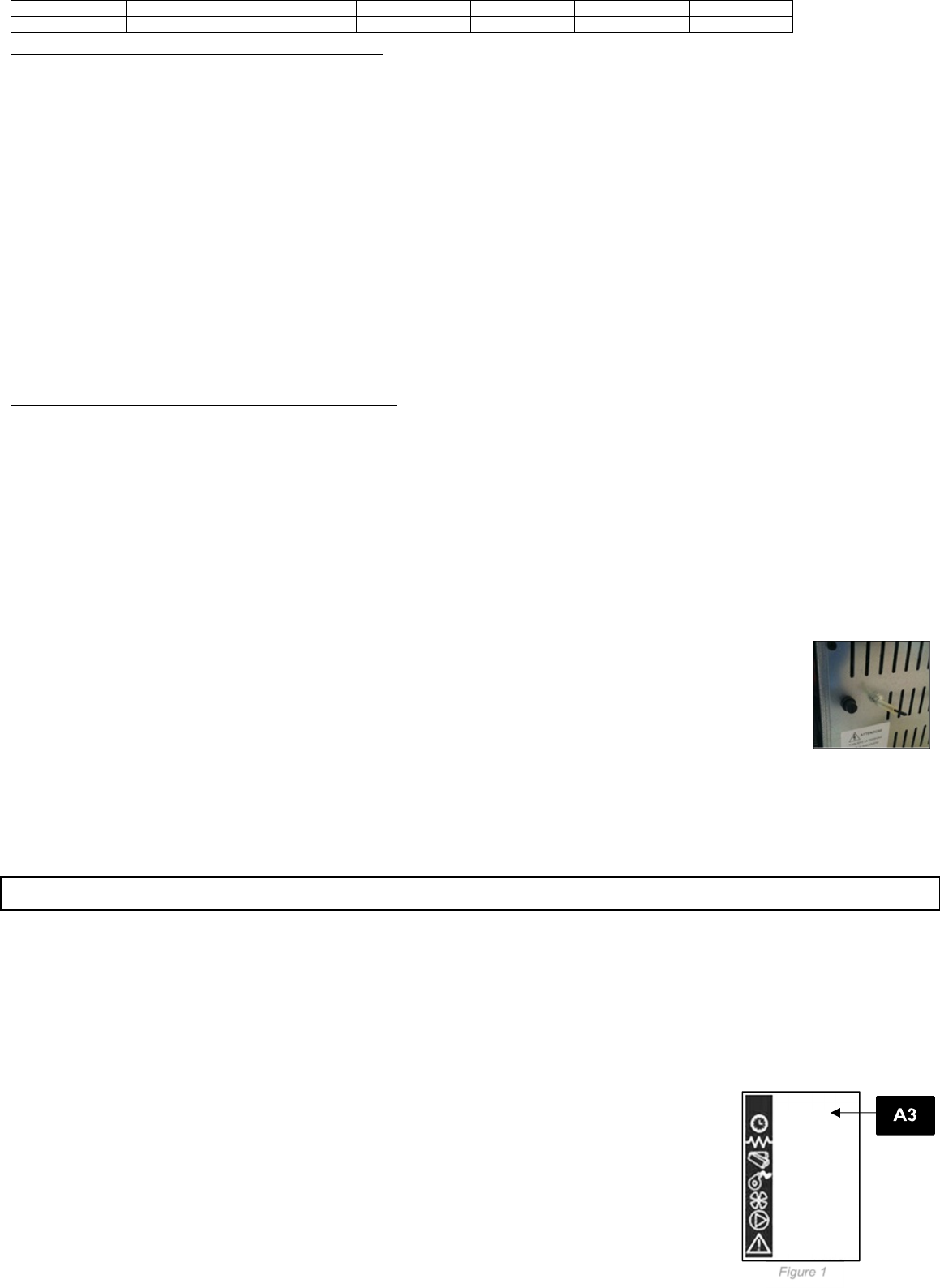
(A3) STATUS p. 3 F-2 and p. 17 figure 1
(A4) DIALOGUE
(A5) HEAT OUTPUT (A5)
Figure 1 p. 17 describes the meaning of the status indicators appearing on the display left side.
Programming: When the LED is lighted, it means that the corresponding component is active p. 17 figure 1
P. 3 F-3 describes the position of the messages visualised during working parameter programming or setting phase.
1. The input (B1) area shows the entered programming values
2. The menu level (B2) area displays the current menu. See chapter dedicated to menu p.17.
BUTTON (P1) - Temperature increase:
When in programming mode, use this button to modify/increase the selected menu value. When in WORK/OFF, use instead this button to increase the room
Libble takes abuse of its services very seriously. We're committed to dealing with such abuse according to the laws in your country of residence. When you submit a report, we'll investigate it and take the appropriate action. We'll get back to you only if we require additional details or have more information to share.
Product:
Forumrules
To achieve meaningful questions, we apply the following rules:
First, read the manual;
Check if your question has been asked previously;
Try to ask your question as clearly as possible;
Did you already try to solve the problem? Please mention this;
Is your problem solved by a visitor then let him/her know in this forum;
To give a response to a question or answer, do not use this form but click on the button 'reply to this question';
Your question will be posted here and emailed to our subscribers. Therefore, avoid filling in personal details.
Register
Register getting emails for Eva Calor Erika at:
new questions and answers
new manuals
You will receive an email to register for one or both of the options.
Get your user manual by e-mail
Enter your email address to receive the manual of Eva Calor Erika in the language / languages: English as an attachment in your email.
The manual is 5,83 mb in size.
You will receive the manual in your email within minutes. If you have not received an email, then probably have entered the wrong email address or your mailbox is too full. In addition, it may be that your ISP may have a maximum size for emails to receive.
If you have not received an email with the manual within fifteen minutes, it may be that you have a entered a wrong email address or that your ISP has set a maximum size to receive email that is smaller than the size of the manual.
The email address you have provided is not correct.
Please check the email address and correct it.
Your question is posted on this page
Would you like to receive an email when new answers and questions are posted? Please enter your email address.