Note that the range values shown need to be converted to the 0-127 MIDI equivalent.
Example:
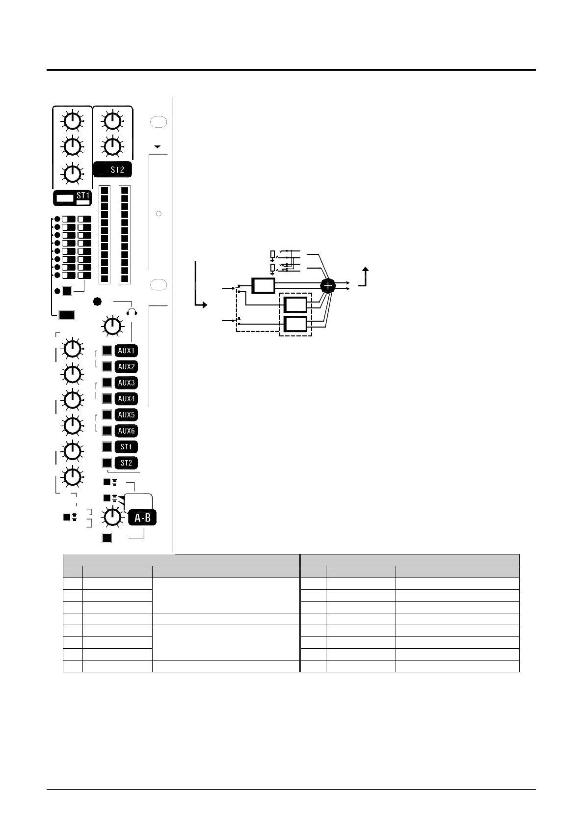
To change the feedback parameter on the Phaser effect. First select the phaser effect on the WZ mixer. The MIDI string should then be generated as follows;
B
n
,16,xx Where Bn defines the string as a control change instruction and n=channel voice message. 16 is CC#22 in hexadecimal and xx is the new value in the range 0-127.
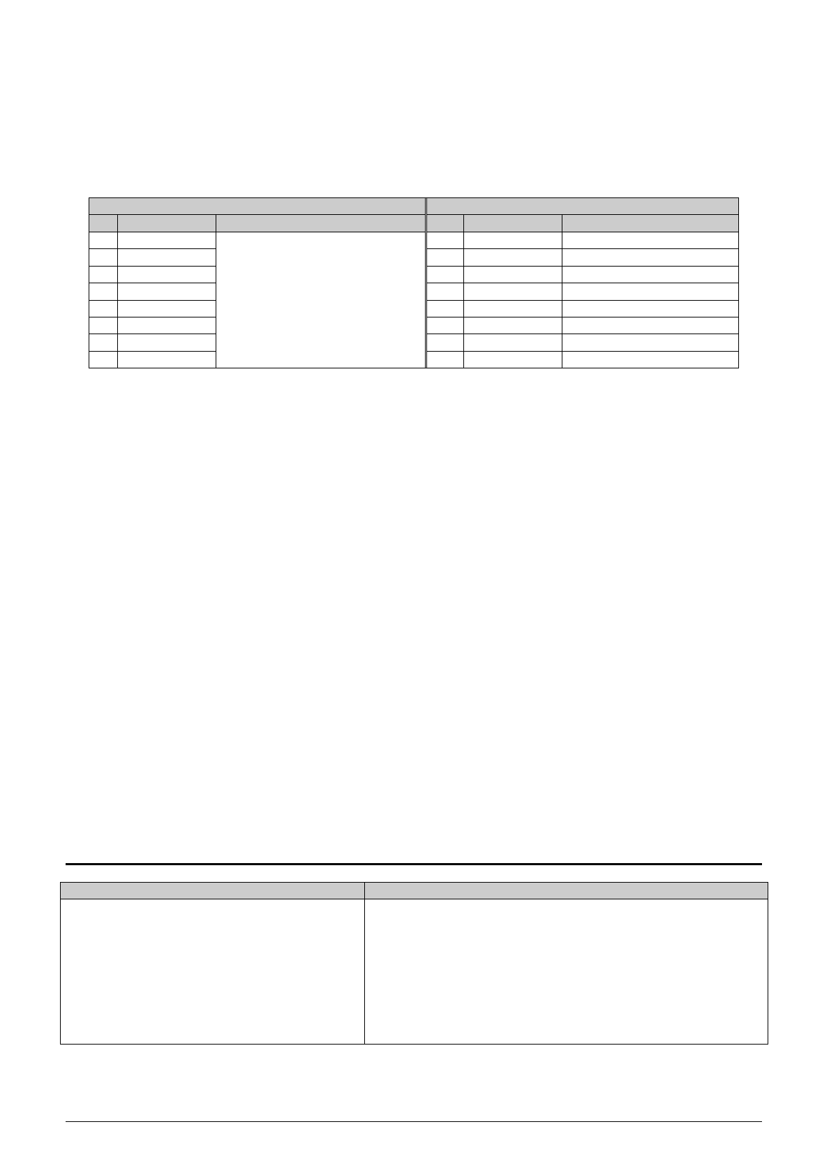
S I N G L E M O D E
D U A L M O D E
Key to FX types:
CH – Chorus
FL – Flange
PH – Phaser
Tr – Tremolo
Pn – Panner
RS – Rotary speaker
PS – Pitch shift
Dn – Detuner
D1 – Mono delay
D2 – Stereo delay
D3 – Ping Pong
D4 – Karaoke
St – Stage
Ro – Room
HA – Hall
PL – Plate
Ch – Chamber
CA – Cathedral
Ar – Arena
GA – Gated
RE – Reverse
Rg – Ring Modulator
Co – Compressor
Cd – Vocoder
D1 – Mono delay
D2 – Stereo delay
D3 – Ping Pong
D4 - Karaoke
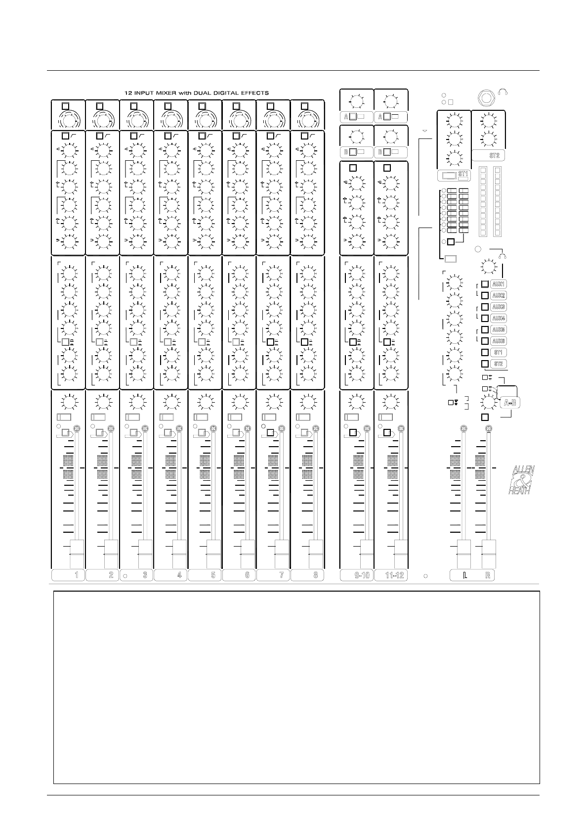
WZ16:2DX
AND
WZ12:2DX U
SER
G
UIDE
23
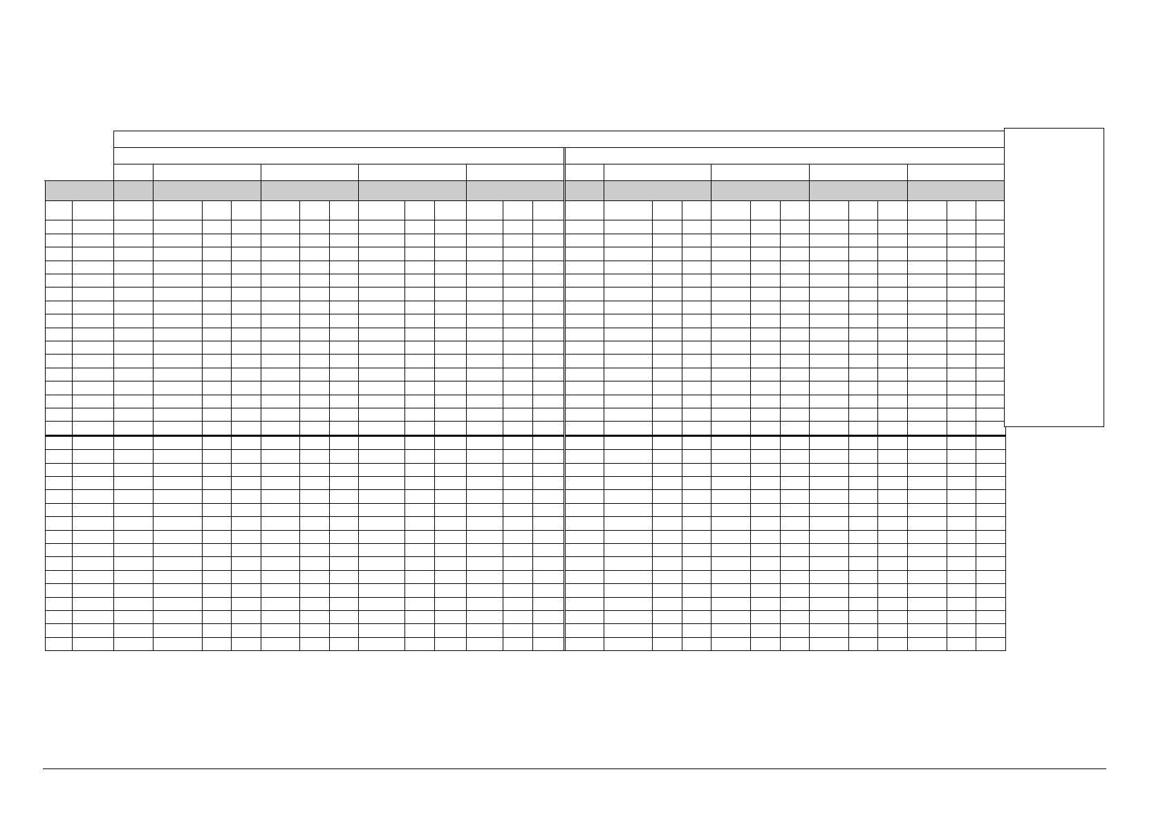
FX Type Selection via MIDI
Note that the 32 FX program types may be changed using MIDI Control Change No 31 as follows:
Libble takes abuse of its services very seriously. We're committed to dealing with such abuse according to the laws in your country of residence. When you submit a report, we'll investigate it and take the appropriate action. We'll get back to you only if we require additional details or have more information to share.
Product:
Forumrules
To achieve meaningful questions, we apply the following rules:
First, read the manual;
Check if your question has been asked previously;
Try to ask your question as clearly as possible;
Did you already try to solve the problem? Please mention this;
Is your problem solved by a visitor then let him/her know in this forum;
To give a response to a question or answer, do not use this form but click on the button 'reply to this question';
Your question will be posted here and emailed to our subscribers. Therefore, avoid filling in personal details.
Register
Register getting emails for Allen-Heath WZ16 mixwizard at:
new questions and answers
new manuals
You will receive an email to register for one or both of the options.
Get your user manual by e-mail
Enter your email address to receive the manual of Allen-Heath WZ16 mixwizard in the language / languages: English as an attachment in your email.
The manual is 3,09 mb in size.
You will receive the manual in your email within minutes. If you have not received an email, then probably have entered the wrong email address or your mailbox is too full. In addition, it may be that your ISP may have a maximum size for emails to receive.
If you have not received an email with the manual within fifteen minutes, it may be that you have a entered a wrong email address or that your ISP has set a maximum size to receive email that is smaller than the size of the manual.
The email address you have provided is not correct.
Please check the email address and correct it.
Your question is posted on this page
Would you like to receive an email when new answers and questions are posted? Please enter your email address.