501977
11
Zoom out
Zoom in
Previous page
1/28
Next page


To obtain the best possible performance and to avoid damage to your
boat, install the Garmin
®
GHP 12 marine autopilot system according
to the following instructions. Professional installation of the autopilot
system is highly recommended. Specic training in rudder steering
and in marine electrical connections is required to properly install the
autopilot system.
Read all installation instructions before proceeding with the
installation. If you experience difculty during the installation, contact
Garmin Product Support.
NOTE: There is an installation checklist on the last page of these
instructions. Remove the last page and refer to the checklist as you
proceed through the GHP 12 installation.

Help us better support you by completing our online registration today.
Go to http://my.garmin.com. Keep the original sales receipt, or a
photocopy, in a safe place.
For future reference, write the serial number assigned to each
component of your GHP 12 system in the spaces provided on page 3.
The serial numbers are located on a sticker on each component.

Contact Garmin Product Support if you have any questions while using
your GHP 12.
In the USA, go to www.garmin.com/support, or contact Garmin USA
by phone at (913) 397.8200 or (800) 800.1020.
In the UK, contact Garmin (Europe) Ltd. by phone at 0808 2380000.
In Europe, go to www.garmin.com/support and click Contact Support
for in-country support information, or contact Garmin (Europe) Ltd. by
phone at +44 (0) 870.8501241.


You are responsible for the safe and prudent operation of your
vessel. The GHP 12 is a tool that will enhance your capability to operate
your boat. It does not relieve you from the responsibility of safely
operating your boat. Avoid navigational hazards and never leave the
helm unattended.
Always be prepared to promptly regain manual control of your boat.
Learn to operate the GHP 12 on calm and hazard-free open water.
Use caution when operating the GHP 12 near hazards in the water, such
as docks, pilings, and other boats.
See the Important Safety and Product Information guide in the product
box for product warnings and other important information.

Equipment to be connected to this product should have a re enclosure
or be provided with a re enclosure.
Always wear safety goggles, ear protection, and a dust mask when
drilling, cutting, or sanding.
Notice
When drilling or cutting, always check the opposite side of the surface.
Be aware of fuel tanks, electrical cables, and hydraulic hoses.
January 2011 190-01289-02 Rev. A Printed in Taiwan
2 GHP12InstallationInstructions



Product Registration .................................................................... 1
Contacting Garmin....................................................................... 1
Important Safety Information ....................................................... 1

Main Components ....................................................................... 3
CCU ...................................................................................................3
ECU ...................................................................................................3
GHC 10 ..............................................................................................3
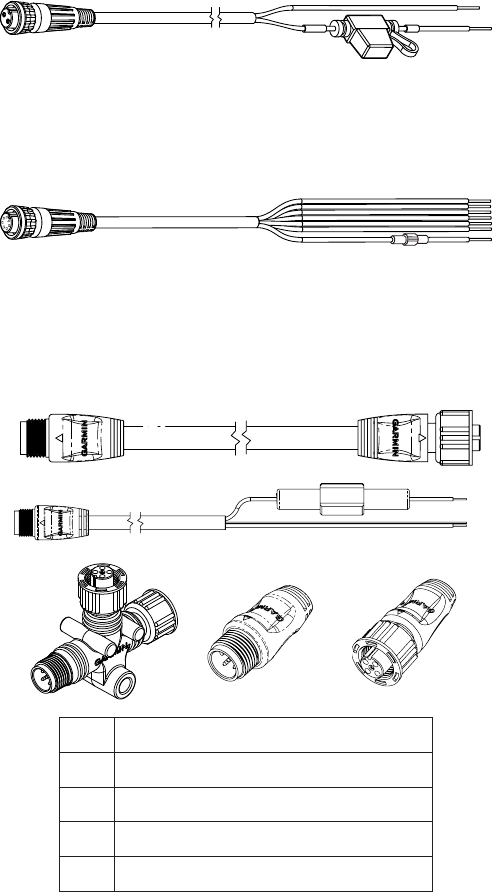
Cables and Connectors ............................................................... 3
CCU/ECU Interconnect Cable ...........................................................3
Alarm..................................................................................................3
ECU Power Cable ..............................................................................4
GHC 10 NMEA 0183 Data Cable .......................................................4
NMEA 2000 Cables and Connectors .................................................4
Tools Needed............................................................................... 4

Mounting and Connection Considerations................................... 5
Dive Unit Mounting and Wiring Considerations .................................5
ECU Mounting and Wiring Considerations ........................................5
CCU Mounting Considerations ..........................................................5
CCU Wiring Considerations ...............................................................5
Alarm Mounting and Wiring Considerations ......................................5
NMEA 2000 Wiring Considerations ...................................................5
GHC 10 Mounting Considerations .....................................................5
GHC 10 Wiring Considerations ..........................................................5
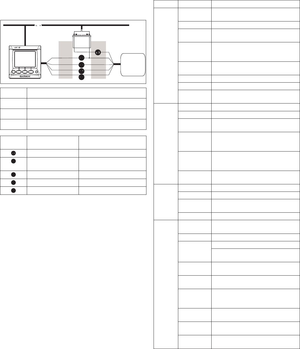
General Connections Diagram .................................................... 6
General Component Layout Diagram .......................................... 7

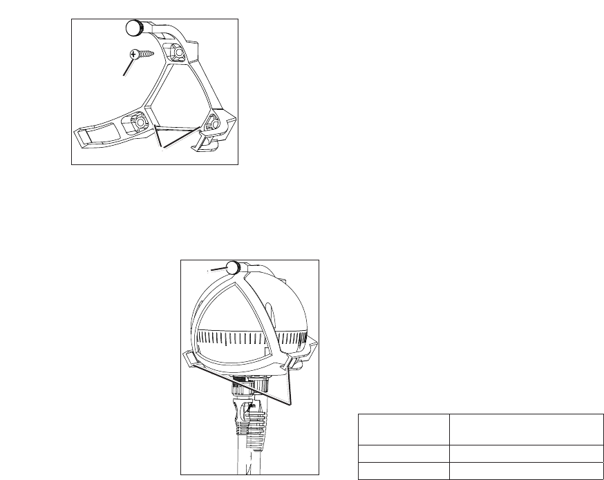
Drive Unit Installation................................................................... 8
Installing a Garmin Dive Unit .............................................................8
Preparing a non-Garmin Dive Unit .....................................................8
ECU Installation ........................................................................... 8
Mounting the ECU .............................................................................8
Connecting the Dive Unit to the ECU ................................................8
Connecting the ECU to Power ...........................................................8
CCU Installation........................................................................... 9
Installing the CCU Mounting Bracket .................................................9
Connecting the CCU ..........................................................................9
Alarm Installation ......................................................................... 9
Mounting the Alarm ............................................................................9
Connecting the Alarm ........................................................................9
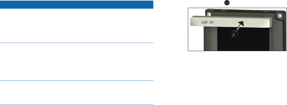
GHC 10 Installation ................................................................... 10
Mounting the GHC 10 ......................................................................10
Connecting the GHC 10 ...................................................................10
Multiple GHC 10 Considerations .....................................................10
Connecting the Devices to a NMEA 2000 Network ................... 11
Building a Basic NMEA 2000 Network for the GHC 10 and the
CCU ...........................................................................................12
Connecting Optional Devices to the GHP 12 Autopilot System . 12
Connecting an Optional NMEA 2000-compatible Device to the
GHP 12.......................................................................................12
NMEA 0183 Connection Considerations .........................................12
Connecting an Optional NMEA 0183-compatible Device to the
GHC 10 ......................................................................................12

Dockside Wizard........................................................................ 13
Performing the Dockside Wizard ............................................... 13
Starting the Dockside Wizard ..........................................................13
Selecting the Drive Unit Class .........................................................13
Selecting the Drive Unit Voltage ......................................................13
Selecting the Clutch Voltage ............................................................13
Calibrating the Rudder .....................................................................13
Tuning a Non-Garmin Drive Unit ......................................................13
Testing the Steering Direction ..........................................................13
Reviewing the Results of the Dockside Wizard ...............................14
Sea Trial Wizard ........................................................................ 14
Important Sea Trial Wizard Considerations ............................... 14
Performing the Sea Trial Wizard................................................ 14
Starting the Sea Trial Wizard ...........................................................14
Calibrating the Compass .................................................................14
Performing the Autotune Procedure ................................................14
Setting North ....................................................................................14
Evaluating the Results of the Autopilot Conguration................ 15
Testing and Adjusting the Autopilot Conguration ............................15
Advanced Conguration Power-on Procedure .......................... 16
Executing and Testing the Advanced Conguration Power-on
Procedure ...................................................................................16
Advanced Conguration Settings .............................................. 16
Manually Running the Automated Conguration Procedures ..........16
Manually Dening Individual Conguration Settings ........................16
Manually Adjusting the Settings for a Non-Garmin Drive Unit .........16
Performing Advanced Tuning Procedures for Non-Garmin Drive
Units ...........................................................................................16

NMEA 0183 Wiring Diagrams .................................................... 18
Specications ............................................................................ 19
NMEA 2000 PGN Information.................................................... 20
CCU .................................................................................................20
GHC 10 ............................................................................................20
NMEA 0183 Information ............................................................ 20
GHP 12 Conguration Settings ................................................. 21
Error and Warning Messages .................................................... 22
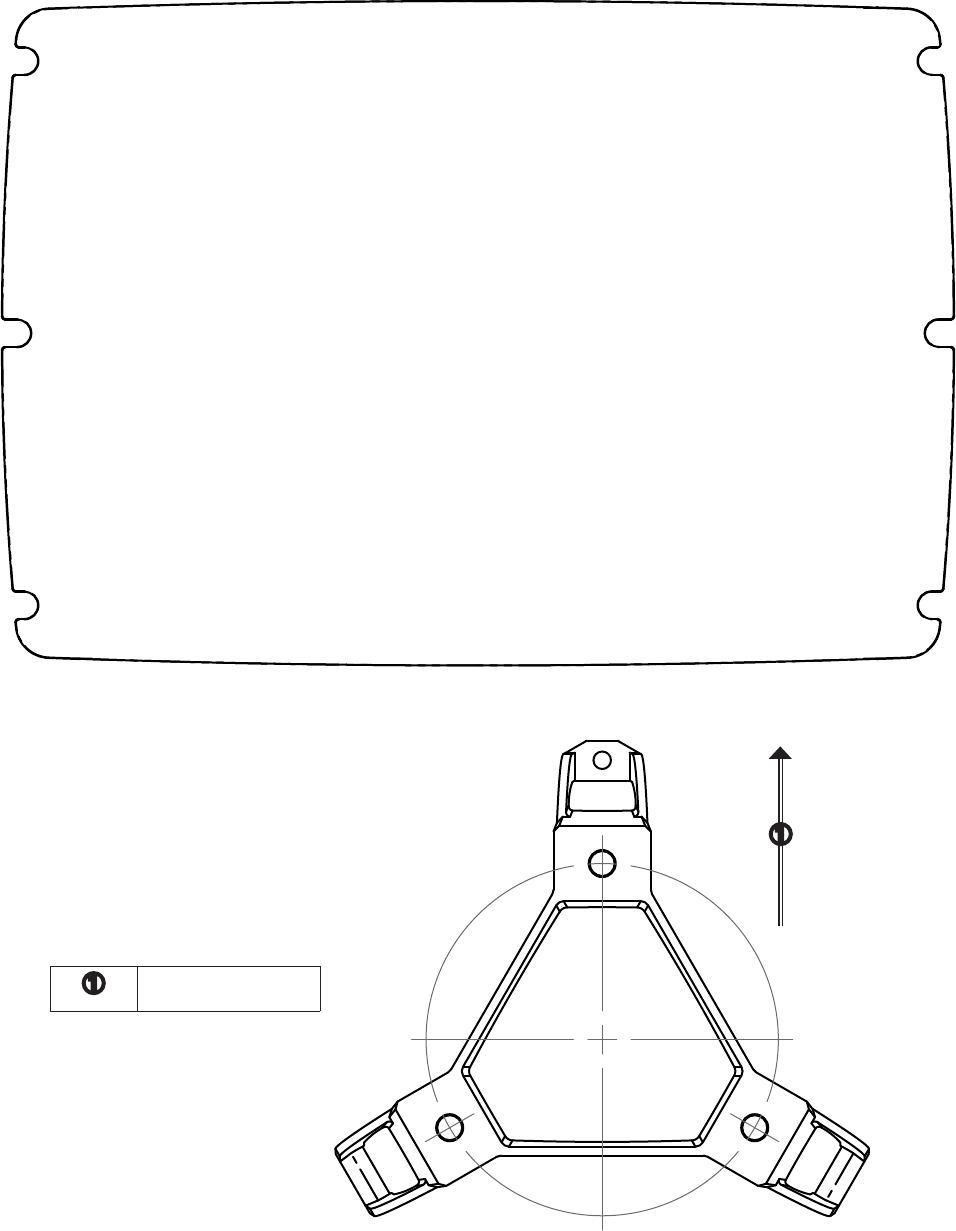
Mounting Templates .................................................................. 25
ECU Mounting Template ..................................................................25
CCU Mounting Template ..................................................................25
GHP 12 Installation Checklist .................................................... 27
GHP12InstallationInstructions 3


The GHP 12 autopilot system consists of multiple components.
Familiarize yourself with all of the components before beginning
installation. You must know how the components operate together in
order to correctly plan the installation on your boat.
As you familiarize yourself with the GHP 12 components, conrm
that your package includes the items listed below. All the components,
except the drive unit, are included in the GHP 12 core box. The drive
unit is sold separately (page 8). If any parts are missing, contact your
Garmin dealer immediately.
Record the serial number of each component in the space provided.

The GHP 12 autopilot system consists of four main components: the
Course Computer Unit (CCU), the Electronic Control Unit (ECU), the
GHC
10 user control interface, and the drive unit (sold separately, see
page 8).

The CCU acts as the brain of the GHP 12. The CCU contains the
sensory equipment used to determine heading. The CCU connects to the
ECU and to the GHC 10 with a single cable. The CCU also connects
to a NMEA 2000
®
network to communicate with the GHC 10, and to
optional NMEA 2000-compatible devices, such as a chartplotter and a
wind sensor (page 11).


The ECU connects to the CCU and to the drive unit. The ECU controls
the drive unit based on information from the CCU. The ECU powers
both the CCU and the drive unit.


The GHC 10 is the primary interface used to operate the GHP 12
autopilot system. Using the GHC 10, you engage and steer the GHP 12.
You also set up and customize the GHP 12 using the GHC 10.
The GHC 10 connects to a NMEA 2000 network to communicate
with the CCU. The GHC 10 also connects with optional NMEA
2000-compatible devices, such as a wind sensor, a water-speed sensor,
or a GPS device, to use advanced features of the GHP 12. If NMEA
2000-compatible devices are not available, you can connect the GHC 10
to optional NMEA 0183-compatible devices instead.


The GHP 12 autopilot system includes multiple cables. These cables
connect the components to power, to each other, to an alarm, and to
optional devices.

This cable connects the CCU to the ECU. A portion of this cable
contains color-coded wires with bare ends. These wires connect the
CCU to the alarm and to the yellow wire from the GHC 10.

When installing the GHP 12 system, you may need to mount the
CCU farther than 16 ft. (5 m) from the ECU. Garmin offers optional
replacement or extension cables for purchase if this is necessary.
 
Replacement 32 ft. (10 m)
Replacement 66 ft. (20 m)
Extension 16 ft. (5 m)
Extension 50 ft (15 m)
Extension 82 ft. (25 m )
Contact your local Garmin dealer or Garmin Product Support for
ordering information.

The alarm provides audible alerts from the GHP 12 (page 9).
4 GHP12InstallationInstructions

This cable powers the ECU (page 8).

Included in the GHC 10 box, this cable connects the GHC 10 to the
yellow wire of the CCU, and to the same ground as the ECU (page
10). This cable can also be used to connect the GHC 10 to optional
NMEA 0183-compatible devices (page 12).

The NMEA 2000 cables connect the CCU and the GHC 10 to the
NMEA 2000 network. Either connect the CCU and the GHC 10 to an
existing NMEA 2000 network using the included T-connectors and drop
cables, use all of the included NMEA 2000 cables and connectors to
build a NMEA 2000 network on your boat if needed (page 11).
NMEA 2000 drop cable, 6 ft. (2 m) (×2)
NMEA 2000 power cable
NMEA 2000 T-connector (×3)
NMEA 2000 terminator, male
NMEA 2000 terminator, female

NMEA 2000 extension cables are available if needed. Contact
your local Garmin dealer or Garmin Product Support for ordering
information.

Safety glasses
Drill and drill bits
3
1
/
2
in. (90 mm) hole saw
Wire cutters/strippers
Phillips and at screwdrivers
Cable ties
Waterproof wire connectors (wire nuts) or heat-shrink tubing and a
heat gun
Marine sealant
Portable or handheld compass (to test for magnetic interference
when determining the best location to install the CCU)
Anti-seize lubricant (optional)
NOTE: Mounting screws are provided for the GHC 10, for the
CCU, for the ECU, and for the pump. If the provided screws are not
appropriate for the mounting surface, you must provide the correct
types of screws.
GHP12InstallationInstructions 5

Before installing the GHP 12 autopilot system, you must plan where all
the components will be located on your boat. Temporarily place all the
components where you intend to install them. Read these considerations
and consult the diagrams on pages 6 and 7 before you begin planning
your installation.
NOTE: There is an installation checklist on the last page of these
instructions. Remove the last page and refer to the checklist as you
proceed through the GHP 12 installation.

The GHP 12 components connect to each other and to power using the
included cables. Ensure that the correct cables reach each component
and that each component is in an acceptable location before mounting
or wiring any components.

The drive unit is sold separately, and must be installed by an
experienced professional in order to correctly steer your boat.
The drive unit must be installed before the ECU is permanently
mounted.
The cables connected to the drive unit cannot be extended.
If you using a non-Garmin drive unit, a GHP 12 drive unit power
cable (sold separately), and a GHP 12 rudder feedback cable (sold
separately) must be used to adapt your drive unit for use with the
GHP 12 (page 8).
The GHP 12 drive unit power cable cannot be extended.

The ECU can be mounted on a at surface facing any direction.
Mounting screws are included with the ECU, but you may need to
provide different screws if the supplied screws are not suitable for
the mounting surface.
The ECU power cable connects to the boat battery, and it can be
extended if needed (page 8).
The ECU must be located within 19 in. (0.5 m) of the drive unit.
The cables connected to the drive unit cannot be extended.

The CCU must be mounted in the forward half of the boat, no
higher than 10 ft. (3 m) above the waterline.
The CCU or the ECU must not be mounted in a location where they
will be submerged or exposed to wash-down.
The CCU must not be mounted near magnetic material,
magnets (speakers and electric motors), or high-current wires.
The CCU must be mounted at least 24 in. (0.6 m) away from
movable or changing magnetic disturbances such as anchors, anchor
chain, wiper motors, and tool boxes.
A handheld compass should be used to test for magnetic interference
in the area where the CCU is to be mounted.
If the handheld compass does not point north when you hold it in
the location you want to mount the CCU, then there is magnetic
interference. Choose another location and test again.
The CCU can be mounted below the waterline if it is not in a
location where it will be submerged or exposed to wash-down.
The CCU bracket must be mounted on a vertical surface or under a
horizontal surface, so that the connected wires hang straight down.
Mounting screws are included with the CCU, but you may need to
provide different screws if the supplied screws are not suitable for
the mounting surface.

The CCU/ECU interconnect cable connects the CCU to the ECU
and is 16 ft. (5 m) long.
If the CCU cannot be mounted within 16 ft. (5 m) of the ECU,
replacement and extension cables are available (page 3).
The CCU/ECU interconnect cable must not be cut.
The CCU/ECU interconnect cable connects the CCU to the GHC 10
with a single yellow signal wire (page 9). The autopilot system will
not power on if this connection is not made.

The alarm should be mounted near the helm station.
The alarm can be mounted under the dashboard if you prefer.
If needed, the alarm wires can be extended with 28 AWG (.08 mm
2
)
wire.

The CCU and the GHC 10 connect to the NMEA 2000 network.
If your boat does not already have a NMEA 2000 network, one can
be built using the included NMEA 2000 cables and connectors
(page 12).
To use advanced features of the GHP 12, optional NMEA
2000-compatible devices, such as a wind sensor, a water-speed
sensor, or a GPS device, can be connected to the NMEA 2000
network.

The mounting location should provide optimal viewing as you
operate your vessel.
The mounting location should allow easy access to the keys on the
GHC 10.
The mounting surface must be strong enough to support the weight
of the GHC 10 and protect it from excessive vibration or shock.
The area behind the surface must allow room for the routing and
connection of the cables.
There should be at least a 3-inch (8 cm) clearance behind the case of
the GHC 10.
The location must be at least 9
1
/
2
in. (0.24 m) from a magnetic
compass, to avoid interference.
The location must be in an area that is not exposed to extreme
temperature conditions (page 19).

You must connect the GHC 10 to the NMEA 2000 network.
For the autopilot to function, you must correctly connect two wires
from the GHC 10 data cable:
The yellow wire from the GHC 10 data cable must be connected
to the yellow wire of the CCU/ECU interconnect cable.
The black wire from the GHC 10 data cable must be connected
to the same ground as the ECU.
Optional NMEA 0183-compatible devices, such as a wind sensor,
a water-speed sensor, or a GPS device, can be wired to the GHC 10
data cable (page 12).
6 GHP12InstallationInstructions

Refer to this diagram for component-interconnection reference only. Follow the detailed installation instructions for each component (pages 8–12).
FEEDBACK
CCU
POWER
DRIVE
  
GHC 10
GHC 10 data cable In order for the autopilot to turn on, the yellow wire from this cable must be connected to the yellow wire
from the CCU/ECU Interconnect cable, and the black wire from this cable must be connected to the same
ground as the ECU (page 10).
NMEA 2000 power
cable
This cable should only be installed if you are building a NMEA 2000 network. Do not install this cable if
there is an existing NMEA 2000 network on your boat (page 12).
The NMEA 2000 power cable must be connected to a 9–16 Vdc power source.
NMEA 2000 network The GHC 10 and the CCU must be connected to the NMEA 2000 network using the included T-connectors
(page 11).
If there is not an existing NMEA 2000 network on your boat, you can build one using the supplied cables
and connectors (page 12).
Drive unit The drive unit must be installed by an experienced professional (page 8).
Drive unit power and
feedback cables

If you are using the GHP 12 with a non-Garmin drive unit, you must purchase a GHP 12 drive unit power
cable and a GHP 12 rudder feedback cable (page 8).
CCU Mount the CCU with the cables pointing straight down (page 9).
ECU The ECU can be mounted in any orientation.
ECU power cable The ECU can be connected to a 12–24 Vdc power source. To extend this cable, use the correct wire gauge
(page 8).
The black wire from the GHC 10 data cable must connect to the same ground as this cable (page 10).
CCU/ECU interconnect
cable
In order for the autopilot to turn on, the yellow wire from this cable must be connected to the yellow wire
from the GHC 10 data cable.
To extend this cable to reach the ECU, purchase the necessary extensions (page 3).
The red and blue wires from this cable connect to the alarm (page 9).
GHP12InstallationInstructions 7

Refer to this diagram for component-layout reference only. Follow the detailed installation instructions for each component (pages 8–12).
  
GHC 10 In order for the autopilot to turn on, the yellow wire from the GHC 10 data cable must be connected to the
yellow wire from the CCU/ECU Interconnect cable, and the black wire from the GHC 10 data cable must
be connected to the same ground as the ECU (page 10).
12-24 Vdc battery The ECU can connect to a 12–24 Vdc power source.
The NMEA 2000 power cable must be connected to a 9–16 Vdc power source.
CCU
The CCU must be installed in the front half of the boat,
no higher than 10 ft. (3 m) above the waterline
Drive unit 
If you are using the GHP 12 with a non-Garmin drive unit, you must purchase a GHP 12 drive unit cable
(page 8).
ECU The ECU can either be connected to a 12 or a 24 Vdc battery.
NMEA 2000 network The GHC 10 and the CCU must be connected to the NMEA 2000 network using the included T-connectors
(page 11).
If there is not an existing NMEA 2000 network on your boat, you can build one using the supplied cables
and connectors (page 12).
8 GHP12InstallationInstructions

After you have planned the GHP 12 installation on your boat and
satised all of the mounting and wiring considerations for your
particular installation, you can begin mounting and connecting the
components.

The drive unit drives the rudder and is sold separately from the GHP 12.
When you purchase a drive unit from Garmin, it will have the correct
cables and connectors.
If you a drive unit is installed on your boat already, you can purchase
GHP 12 drive unit cables (not included) to adapt your drive unit for use
with the GHP 12.

Use the installation instructions provided with the drive unit to
install it on your boat.

In order to use a non-garmin drive unit with the GHP 12, you must
install both the GHP 12 drive unit power cable and the GHP 12 rudder
feedback cable. Both cables are sold separately.
1. If your drive unit has cables connected, disconnect the cables.
2. Consult the documentation provided by the manufacturer of your
drive unit to identify the connections on your drive unit.
3. Connect the GHP 12 drive unit power cable (not included) to your
drive unit, based on the wire colors and functions dened below.
 
Red Drive unit positive
Black Drive unit negative
Blue Clutch power (cut and tape this wire if your drive unit
has no clutch)
White Clutch ground (cut and tape this wire if your drive
unit has no clutch)
The GHP 12 drive unit power cable cannot be extended.
4. Connect the GHP 12 rudder feedback cable (not included) to your
drive unit, based on the wire colors and functions dened below.
 
Red Feedback positive (+)
Black Feedback negative (-)
Yellow Feedback wiper
If necessary, extend the appropriate wire with 22 AWG (.33 mm
2
)
wire.
5. If necessary, use the installation instructions provided with the drive
unit to install it on your boat.

The GHP 12 drive unit power cable is shipped with a 40 A, blade-type
fuse. The included fuse must not be used if it is not the appropriate fuse
for your drive unit.
1. Consult the manufacturer of your drive unit to determine the correct
fuse type.
2. Select an option:
If the 40 A fuse is appropriate, install it in the fuse holder.
If your drive unit requires a different fuse, install the correct fuse
for your drive unit.

To install the ECU, you must mount it to your boat, connect it to the
drive unit, and prepare the battery wiring.

Before you can install the ECU, you must select a mounting location
and determine the correct mounting hardware (page 5).
1. Cut out the mounting template provided on page 25.
2. Tape the template to the mounting location.
3. Drill pilot holes at the four mounting locations.
4. Use screws to mount the ECU.

Connect the two cables from the drive unit to the connectors marked
DRIVE and FEEDBACK on the ECU.
The connectors are keyed and color coded to the appropriate ttings
on the wires.

Notice
Do not remove the in-line fuse holder from the battery cable when
connecting to the battery. If you remove the in-line fuse holder, you will
void the GHP 12 warranty and possibly damage the GHP 12 autopilot
system.
You should connect the ECU power cable directly to the boat battery
if possible. Although it is not recommended, if you connect the power
cable to a terminal block or other source, connect it through a 40 A fuse.
If you plan to route the ECU through a breaker or a switch near the
helm, consider using an appropriately sized relay and control wire
instead of extending the ECU power cable.
1. Route the connector-terminated end of the ECU power cable to the
ECU, but do not connect it to the ECU.
2. Route the bare-wire end of the ECU power cable to the boat battery.
If the wire is not long enough, it can be extended. Consult the table
to determine the correct wire gauge for an extended run.
 
10 ft. (3 m) 12 AWG (3.31 mm
2
)
15 ft. (4.5 m) 10 AWG (5.26 mm
2
)
20 ft. (6 m) 10 AWG (5.26 mm
2
)
25 ft. (7.5 m) 8 AWG (8.36 mm
2
)
3. Connect the black wire (-) to the negative (-) terminal of the battery.
4. Connect the red wire (+) to the positive (+) terminal of the battery.
5. Do not connect the ECU power cable to the ECU.
Connect the power cable to the ECU only after you install all of
the other GHP 12 components.
GHP12InstallationInstructions 9

To install the CCU, you must mount it to your boat, connect it to the
ECU, connect it to a NMEA 2000 network, and connect it to the alarm
and to the yellow CCU signal wire on the GHC 10.

Before you can mount the CCU, you must select a location and
determine the correct mounting hardware (page 5).
The CCU bracket has two portions, the mounting portion and the
securing portion.
1. Cut out the mounting template provided on page 25.
2. Tape the template to the mounting location.
If you are installing the CCU on a vertical surface, install the
mounting portion of the bracket with an opening
at the bottom.
3. Drill pilot holes at the three mounting locations.
4. Use screws
to secure the mounting portion of the CCU bracket.

1. Connect the CCU/ECU interconnect cable and the NMEA 2000
drop cable to the CCU.
2. Place the CCU in the mounting
portion of the CCU bracket with
the wires hanging straight down
.
3. Place the securing portion of the
bracket over the ball and snap
it it into the mounting portion
of the bracket, starting with the
two arms
that do not have the
thumbscrew
.
4. With the cables hanging straight down, connect the arm with the
thumbscrew.
The cables must hang straight down for the CCU to accurately read
your heading.
5. Hand-tighten the thumbscrew until the CCU is held rmly in the
bracket.
Do not overtighten the thumbscrew.

1. Route the connector-terminated end of the CCU/ECU interconnect
cable to the ECU and make the connection.
2. Route the wires from the bare-wire portion of the cable to the CCU/
ECU interconnect cable.
Route the red and blue wires to the location where you plan to
install the alarm (page 9).
If the cable is not long enough, extend the appropriate wires with
28 AWG (.08 mm
2
) wire.
Route the yellow wire to the location where you plan to install
the GHC 10 (page 10).
If the cable is not long enough, extend the yellow wire with 22
AWG (.33 mm
2
) wire.
3. Cut and tape the remaining bare wires; they are not used.

The alarm audibly alerts you to important GHP 12 events. It must be
installed near the helm station.

Before you can mount the alarm, you must select a mounting location
(page 5).
Secure the alarm with cable ties or other appropriate mounting
hardware (not included).

1. Route the alarm-cable to the bare-wire end of the CCU/ECU
interconnect cable.
If the cable is not long enough, extend the appropriate wires with 28
AWG (.08 mm
2
) wire.
2. Connect the cables, based on the table below.




White (+) Red (+)
Black (-) Blue (-)
3. Solder and cover all bare-wire connections.
10 GHP12InstallationInstructions

Install the GHC 10 by ush-mounting it in the dashboard near the helm,
connecting it to the yellow wire from the CCU/ECU interconnect cable,
and connecting it to a NMEA 2000 network.
To use advanced features of the GHP 12, optional NMEA
2000-compatible or NMEA 0183-compatible devices, such as a wind
sensor, a water-speed sensor, or a GPS device, can be connected to
the NMEA 2000 network or connected to the GHC 10 through NMEA
0183.

Notice
The temperature range for the GHC 10 is from 5°F to 158°F (from
-15°C to 70°C). Extended exposure to temperatures outside of this
range (in storage or operating conditions) may cause failure of the
LCD screen or other components. This type of failure and related
consequences are not covered by the manufacturers limited warranty.
If you are mounting the GHC 10 in berglass, when drilling the
four pilot holes, it is recommended to use a countersink bit to drill a
clearance counterbore through only the top gel-coat layer. This will
help to avoid any cracking in the gel-coat layer when the screws are
tightened.
Stainless-steel screws may bind when screwed into berglass and
overtightened. Garmin recommends applying an anti-galling, stainless
anti-seize lubricant to the screws before installing them.
Before you can mount the GHC 10, you must select a mounting location
(page 5).
1. Trim the ush-mount template and ensure it will t in the location
where you plan to mount the GHC 10.
The ush-mount template is included in the product box, not in
these instructions.
The ush-mount template has adhesive on the back.
2. Remove the protective liner from the adhesive on the back of the
template and apply it to the location where you plan to mount the
GHC 10.
3. If you will be cutting the hole with a jigsaw instead of a 3
17
/
32
in. (90
mm) hole saw, use a
3
/
8
in. (10 mm) drill bit to drill a pilot hole as
indicated on the template to begin cutting the mounting surface.
4. Using the jigsaw or the 3.5
in. (90 mm) hole saw, cut the mounting
surface along the inside of the dashed line indicated on the ush-
mount template.
5. If necessary, use a le and sandpaper to rene the size of the hole.
6. Place the GHC 10 into the cutout to conrm that the four mounting
holes are correct.
7. Select an option:
If the mounting holes are correct, proceed to step 8.
If the mounting holes are not correct, mark the correct locations
of the four mounting holes
8. Remove the GHC 10 from the cutout.
9. Drill the four
1
/
8
in. (3.2 mm) pilot holes.
If you are mounting the GHC 10 in berglass, use a countersink bit
as advised in the notice.
10. Remove the remainder of the template.
11. Place the GHC 10 into the cutout.
12. Securely fasten the GHC 10 to the mounting surface using the
supplied screws.
If you are mounting the GHC 10 in berglass, use a anti-galling
lubricant as advised in the notice.
13. Snap the mounting covers
into place.

For the autopilot system to function correctly, you must connect two
wires from the GHC 10 data cable (yellow and black).
1. Connect the yellow wire from the GHC 10 data cable to the yellow
wire from the CCU/ECU interconnect cable.
If the cable is not long enough, extend the yellow wire with 22
AWG (.33 mm
2
) wire.
2. Connect the black wire from the GHC 10 data cable to the same
ground location as the ECU.
If the cable is not long enough, extend the black wire with 22 AWG
(.33 mm
2
) wire.
3. Solder and cover all bare-wire connections.

You can install multiple GHC 10 devices (sold separately) to control the
autopilot from different locations on the boat.
All additional GHC 10 devices must be at software version 3.0 or
later.
All additional GHC 10 devices must be connected to the
NMEA 2000 network (page 11).
To use an additional GHC 10 to turn on the autopilot, connect the
yellow and black wires from the additional GHC 10 to the same
wires as the primary GHC 10.
If you connect additional GHC 10 devices to turn on the
autopilot, you must turn them all off to turn off the autopilot.
If you do not connect an additional GHC 10 to turn on the
autopilot, then the additional GHC 10 will enter standby mode
when you turn it off, and the autopilot will remain on until
turned off by the primary GHC 10.
GHP12InstallationInstructions 11


Notice
If you have an existing NMEA 2000 network on your boat, it should
already be connected to power. Do not connect the included NMEA
2000 power cable to an existing NMEA 2000 network, because only
one power source should be connected to a NMEA 2000 network.
You can connect the GHC 10 to the CCU through an existing NMEA
2000 network. If you do not have an existing NMEA 2000 network on
your boat, all the parts needed to build one are supplied in the GHP 12
package (page 12).
Optionally, you can connect NMEA 2000-compatible devices, such as
a wind sensor, a water-speed sensor, or a GPS device, to your NMEA
2000 network to use the advanced features of the GHP 12.
For more information on NMEA 2000, go to www.garmin.com.

1. Determine where to connect the GHC 10
to your existing NMEA
2000 backbone
.
2. Disconnect one side of a NMEA 2000 T-connector from the
network.
3. If necessary, to extend the NMEA 2000 network backbone, connect
a NMEA 2000 backbone extension cable (not included) to the side
of the disconnected T-connector.
4. Add the included T-connector
for the GHC 10 to the NMEA
2000 backbone by connecting it to the side of the disconnected
T-connector or backbone extension cable.
5. Route the included drop cable
to the bottom of the T-connector
added in step 4, and connect it to the T-connector.
If the included drop cable is not long enough, you can use a drop
cable up to 20 ft. (6 m) long (not included).
6. Connect the drop cable to the to the GHC 10.
7. Connect the drop cable to the T-connector you added in step 3, and
to the GHC 10.
NOTE: In order for the autopilot to turn on, the yellow wire from
the GHC 10 data cable be connected to the yellow wire from the
CCU/ECU Interconnect cable, and the black wire from the GHC 10
data cable must be connected to the same ground as the ECU (page
10).

1. Determine where to connect the CCU
to your existing NMEA
2000 backbone
.
2. Disconnect one side of a NMEA 2000 T-connector from the
network.
3. If necessary, to extend the NMEA 2000 network backbone, connect
a NMEA 2000 backbone extension cable (not included) to the side
of the disconnected T-connector.
4. Add the included T-connector
for the CCU to the NMEA
2000 backbone by connecting it to the side of the disconnected
T-connector or backbone extension cable.
5. Route the included drop cable
to the bottom of the T-connector
added in step 4, and connect it to the T-connector.
If the included drop cable is not long enough, you can use a drop
cable up to 20 ft. (6 m) long (not included).
6. Connect the drop cable to the to the CCU.
12 GHP12InstallationInstructions


Notice
You must connect the included NMEA 2000 power cable to the boat
ignition switch, or through another in-line switch. The GHC 10 will
drain your battery if the NMEA 2000 power cable is connected to the
battery directly.
1. Connect the three T-connectors
together by their sides.
+
-
2. Connect included NMEA 2000 power cable
to a 12 Vdc power
source
through a switch.
Connect to the ignition switch
of the boat if possible, or through
an in-line switch (not included).
3. Connect the NMEA 2000 power cable to one of the T-connectors.
4. Connect one of the included NMEA 2000 drop cables
to one of
the T-connectors and to the GHC 10
.
5. Connect the other included NMEA 2000 drop cable to the other
T-connector and to the CCU
.
6. Connect the male and female terminators
to each end of the
combined T-connectors.
NOTE: The GHC 10 must connect to the CCU with the yellow
CCU signal wire in the GHC 10 data cable. The black wire must
connect to CCU ground (page 10).


To use advanced features of the GHP 12, optional NMEA
2000-compatible or NMEA 0183-compatible devices, such as a wind
sensor, a water-speed sensor, or a GPS device, can be connected to the
NMEA 2000 network or to the GHC 10 through NMEA 0183.


1. Add an additional T-connector (not included) to the NMEA 2000
network.
2. Connect the device to the T-connector by following the instructions
provided with the device.

To identify the Transfer (Tx) A(+) and B(-) wires for your NMEA
0183-compatible device, consult the installation instructions for
your device.
When connecting NMEA 0183 devices with two transmitting and
two receiving lines, it is not necessary for the NMEA 2000 bus and
the NMEA 0183 device to connect to a common ground.
When connecting a NMEA 0183 device with only one transmitting
(Tx) line or with only one receiving (Rx) line, the NMEA 2000
bus and the NMEA 0183 device must be connected to a common
ground.


1. Determine the NMEA 0183 wiring assignments of your NMEA
0183-compatible device.
2. Refer to the table below to wire your NMEA 0183-compatible
device to the GHC 10.



Black CCU signal ground
Yellow CCU signal
Blue Tx/A (+)
White Tx/B (-)
Brown Rx/A (+)
Green Rx/B (-)
Three examples of various wiring situations are provided in the
appendix (page 18).
3. If necessary, use 22 AWG (.33 mm
2
) twisted-pair wire for extended
runs of wire.
4. Solder and cover all bare-wire connections.
GHP12InstallationInstructions 13

The GHP 12 must be congured and tuned to your boat dynamics.
Use the dockside wizard and the sea trial wizard on the GHC 10 to
congure the GHP 12. These wizards walk you through the necessary
conguration steps.

Notice
If you perform the dockside wizard while your boat is out of the water,
provide rudder-movement clearance to avoid damage to the rudder or
other objects.
You can complete the dockside wizard while your boat is in or out of
the water. If your boat in the water, it must be stationary while you
complete the wizard.

1. Turn on the GHP 12.
The rst time you turn on the GHP 12, you are prompted to
complete a short setup sequence on the GHC 10.
2. If necessary, complete the setup sequence.
3. Start the dockside wizard (page 13).
4. Select the vessel type.
5. Select the drive unit class (page 13).
6. If you have a non-Garmin drive unit, select the drive unit voltage
(page 13).
7. If you have a non-Garmin drive unit, select the clutch voltage
(page 13).
8. Calibrate the rudder (page 13).
9. If you have a non-Garmin drive unit, tune the drive unit (page 13).
10. Test the steering direction (page 13).
11. Review the wizard results (page 14).

1. After you complete the initial setup, select an option:
If the dockside wizard starts automatically, proceed to step 2.
If the dockside wizard does not start automatically, select Menu
> Setup > Dealer Autopilot Conguration > Wizards >
Dockside Wizard.
2. Select Begin.

If you installed a Garmin Class A drive unit, select Class A.
If you have a non-Garmin drive unit, select Other.

Notice
Providing an incorrect drive-unit-voltage value for your non-Garmin
drive unit can damage your drive unit.
1. Consult the manufacturer of your non-Garmin drive unit to
determine the drive-unit voltage.
2. Select the voltage approved for your drive-unit motor.

Notice
Providing an incorrect clutch-voltage value for your non-Garmin drive
unit can damage your drive unit.
1. Consult the manufacturer of your non-Garmin drive unit to
determine the drive-unit-clutch voltage.
2. Select the voltage approved for your drive-unit clutch.

NOTE: If an error appears during these steps, the rudder feedback
sensor may have reached its limit. Make sure the feedback sensor has
been installed correctly. If the problem persists, bypass this error by
moving the rudder to the farthest position that does not report an error.
1. Position the rudder so that the boat would steer fully starboard and
select OK.
2. After the starboard calibration is complete, position the rudder so
that the boat would steer fully port and select OK.
3. After the port calibration is complete, center the rudder position, let
go, and select Begin.
The autopilot will take control of the rudder.
4. Wait while the autopilot calibrates the rudder.
5. Select an option:
If the calibration completed successfully, select OK.
If the calibration did not complete successfully, repeat steps 1–5.

If you installed a non-Garmin drive unit, you must calibrate the drive
unit for use with the GHP 12.
1. Center the rudder position, let go, and select Continue.
The autopilot will take control of the rudder as it tunes the drive
unit.
2. When the process is complete, select Done.
If you encounter an error during the tuning process, repeat the
tuning procedure.
NOTE: If needed, you can further rene the tuning later (page 16).

1. Use the arrows on the GHC 10 to test the steering direction.
When you select the right arrow, the rudder should turn so that the
boat would steer to the right, and when you select the left arrow, the
rudder should turn so that the boat would steer to the left.
2. Select Continue.
3. Select an option:
If the steering test turns the boat in the correct direction, select
Yes.
If the steering test turns the boat in the opposite direction, select
No.
4. If you selected No in step 3, repeat steps 1–2.
14 GHP12InstallationInstructions

The GHC 10 displays the values you chose when you ran the Dockside
Wizard.
1. Examine the results of the dockside wizard.
2. Select any incorrect value and select Select.
3. Correct the value.
4. Repeat steps 2 and 3 for all incorrect values.
5. When you are nished reviewing the values, select Done.

The sea trial wizard congures the fundamental sensors on the
autopilot, and it is extremely important to complete the wizard in
conditions appropriate for your boat.
You must perform the sea trial wizard while under motor, and not while
under sail.

Complete the sea trial wizard in calm water. Because the nature of calm
water is relative to the size and shape of your boat, before you begin the
sea trial wizard, you must drive your boat to a location where:
Your boat does not rock while sitting still or moving very slowly.
Your boat is not signicantly affected by the wind.
While completing the Sea Trial Wizard in calm water, you must:
Keep the weight on your boat balanced. DO NOT move around
on the boat while completing any of the steps in the Sea Trial
Wizard.
Keep the sails lowered.
Keep the motor in position that drives the boat in a straight
direction.

1. Drive your boat to an open area of calm water.
2. Start the sea trial wizard.
3. Calibrate the compass.
4. Perform the autotune procedure.
5. Set north.
6. If necessary, set the ne heading adjustment.

Before you start the sea trial wizard, you must drive to an open area of
calm water.
1. Select Menu > Setup > Dealer Autopilot Conguration >
Wizards > Sea Trial Wizard.
2. Select Begin.

1. Drive your boat at cruising speed in a straight line.
2. Select Begin, and continue to drive in a straight line.
3. When instructed, turn the boat slowly clockwise, taking care to
make the turn as steady and at as possible.
Turn slowly so that the boat DOES NOT list.
After you successfully complete the calibration, the GHC 10
displays a completion message.
4. Select an option:
If the calibration completes successfully, select Done.
If the calibration fails, select Retry and repeat steps 1–4.

Before you begin the Autotune procedure, you must have a large stretch
of open water available.
1. Adjust the throttle so that the boat travels at a typical cruising speed
that provides responsive steering.
2. Select Begin.
The boat performs a number of zigzag motions while the Autotuning
is in progress.
The GHC 10 displays a completion message.
3. Select an option:
If the autotune completed successfully, select Done and take
manual control of the boat.
If the autotune failed, increase the throttle and select Retry.
4. If autotune fails again, repeat steps 1–3 until the autotune completes
successfully.
5. If the autotune procedure continues to fail after you reach maximum
cruising speed, reduce your speed to the initial autotune speed
and select Alternate Autotune to begin an alternate autotuning
procedure.

To complete this conguration, you must have at least 45 seconds of
hazard-free, open water available.
This procedure appears if you connect an optional GPS device to the
GHP 12 (page 12), and the device has acquired a GPS position. If you
do not have a GPS device connected, you are prompted to set the ne
heading adjustment (page 14).
1. Drive the boat in a straight line at cruising speed, and select Begin.
The GHC 10 displays a completion message when the calibration is
compete.
2. Select an option:
If the calibration completed successfully, select Done.
If the calibration failed, repeat steps 1–2.

This procedure appears only if you do not have an optional GPS device
connected to the GHP 12 (page 12). If you do have a GPS device
installed on your boat that has acquired a GPS position, are prompted to
set north instead (page 14).
1. Using a handheld compass, identify north.
2. Adjust the ne heading setting until it matches north on the
magnetic compass.
3. Select Done.
GHP12InstallationInstructions 15


1. Test the autopilot at a slow speed.
2. If necessary, adjust the gain setting.
3. If necessary, adjust the acceleration limiter setting.
4. Test the autopilot at a higher speed (normal operating conditions).
5. If necessary, adjust the gain and acceleration limiter settings.

1. Drive the boat in one direction with the autopilot engaged (heading
hold).
The boat should not oscillate signicantly; however, a small amount
of oscillation is normal.
2. Turn the boat in one direction using the autopilot and observe the
behavior.
The boat should turn smoothly, not too quickly or too slowly.
When you turn the boat using the autopilot, the boat should
approach and settle on the desired heading with minimal
overshoot and oscillation.
3. Select an option:
If the boat turns too quickly or too sluggishly, adjust the
autopilot acceleration limiter (page 15).
If the heading hold oscillates signicantly or the boat does not
correct when turning, adjust the autopilot gain (page 15).
If the boat turns smoothly, the heading hold oscillates only
slightly or not at all, and the boat adjusts the heading correctly,
proceed to step 5.
4. Repeat steps 2 and 3 until the boat turns smoothly the heading hold
oscillates only slightly or not at all, and the boat adjusts the heading
correctly.
5. Repeat steps 1–4 at faster speeds.

NOTE: When you manually adjust the acceleration limiter, make
relatively small adjustments. Test the change before making additional
adjustments.
1. Turn on the GHP 12 using the advanced conguration power-on
procedure (page 16).
2. On the GHC 10, select Menu > Setup > Dealer Autopilot
Conguration > Autopilot Tuning > Acceleration Limiter.
3. Select an option:
Increase the setting if the autopilot turns too quickly,
Decrease the setting if the autopilot turns too slowly.
4. Test the autopilot conguration, and repeat steps 2 and 3 until the
GHP 12 performance is satisfactory.

NOTE: When you manually adjust the rudder gain (or counter gain),
make relatively small adjustments, and adjust only one value at a time.
Test the change before making additional adjustments.
1. Turn on the GHP 12 on using the advanced conguration power-on
procedure (page 16).
2. On the GHC 10, select Menu > Setup > Dealer Autopilot
Conguration > Autopilot Tuning > Rudder Gains.
3. Select an option:
Select Rudder Gain to adjust how tightly the rudder holds the
heading and makes turns. If you set this value too high, the
autopilot may be overactive, attempting to constantly adjust
the heading at the slightest deviation. An overactive autopilot
can cause excess wear and tear on the drive unit, and drains the
battery at a faster-than-normal rate.
Select Counter Gain to adjust how tightly the rudder corrects
the turn overshoot. If you set this value too high, the autopilot
can overshoot the turn again when attempting to counter the
original turn.
4. Test the autopilot conguration, and repeat steps 2 and 3 until the
GHP 12 performance is satisfactory.
16 GHP12InstallationInstructions

Advanced conguration options are not available on the GHC 10 under
normal conditions. To access the advanced conguration settings of the
GHP 12, use the advanced conguration power-on procedure.


Before you begin this task, you must disconnect power to the GHC 10
by unplugging it. You can also disconnect power to the GHC 10 by
turning off the power to the NMEA 2000 network.
1. While the GHC 10 is disconnected from power, hold both the center
and the right soft keys
.
2. While holding the center and the right soft keys, connect power to
the GHC 10 and hold the power key
.
3. Release all three keys when the heading screen appears.
4. From the heading screen, select Menu > Setup.
If the option for Dealer Autopilot Conguration is available, you
performed the advanced conguration power-on procedure correctly.

You can run the Autotune automated conguration process, calibrate the
compass, and dene north on the GHP 12 through the GHC 10 without
running the wizards. You can also dene each setting individually,
without running the conguration processes.


1. Turn on the GHC 10 using the advanced conguration power-on
procedure (page 16).
2. From the Heading screen, select Menu > Setup > Dealer Autopilot
Conguration > Automated Setup.
3. Select Autotune, Calibrate Compass, or Set North.
4. Follow the on-screen instructions (page 13).

1. Turn on the GHC 10 using the advanced conguration power-on
procedure (page 16).
2. From the Heading screen, select Menu > Setup > Dealer Autopilot
Conguration.
3. Select the a setting category.
4. Select a setting to congure.
Descriptions of each setting are available in the appendix (page 21).
5. Congure the value of the setting.


Notice
Providing an incorrect drive-unit-voltage, clutch-voltage, or max-
current value for your non-Garmin drive unit can damage your drive
unit.
NOTE: If you adjust any of these values or run any of these tuning
procedures, you must re-run the autotune procedure (page 16).
1. Turn on the GHC 10 using the advanced conguration power-on
procedure (page 16).
2. From the Heading screen, select Menu > Setup > Dealer Autopilot
Conguration > Steering System Setup > Drive Unit Type >
Other.
3. Select an option:
Select Generic Tune to re-run the tuning procedure you
completed during the dockside wizard (page 13).
Select Drive Unit Voltage to set the drive-unit voltage according
to the specications provided by your drive-unit manufacturer.
Select Clutch Voltage to set the clutch voltage according to the
specications provided by your drive-unit manufacturer.
Select Drive Unit Max Current to set the drive-unit rated
current value according to the specications provided by your
drive-unit manufacturer.
Select Advanced Tuning to perform high-level drive unit
adjustments (page 16).
Select Restore Defaults to reset the non-Garmin drive unit to
default values.
You must perform the generic tune procedure if you reset your
drive unit to the default values.


Notice
Perform these procedures only if you completely understand the
concepts of drive-unit speed and error tolerance as dened below.
Incorrectly setting these values can damage your drive unit, drain
your battery at a faster-than-normal rate, or result in poor autopilot
performance.
For almost every non-Garmin drive-unit installation, the generic
tuning procedure performed during the dockside wizard is sufcient
to calibrate the drive unit to the GHP 12. Use the advanced tuning
procedures only if you would like to make slight adjustments to the
performance of the drive unit.

The speed of the drive unit determines how quickly it reacts to
commands from the autopilot.
If you set the speed value too low, the drive unit will appear slow and
take a long time to respond to commands from the autopilot.
If you set the speed value too high, the drive unit will react too quickly
and can force the rudder to the stops at a high rate of speed, potentially
damaging the drive unit or rudder stops as well as draining your battery
at a faster-than-normal speed.
1. From the Heading screen, select Menu > Setup > Dealer Autopilot
Conguration > Steering System Setup > Drive Unit Type >
Other > Advanced Tuning > Tune Speed.
GHP12InstallationInstructions 17
2. Center the rudder position, let go of the rudder control, and select
Begin.
A graph appears. The red line
represents the intended position
of the rudder. The blue line
represents the actual position of the
rudder.
3. Select Tune, and observe the graph.
The intended rudder position (indicated by the red line) moves
from +5° to -5° each time you select Tune, and the drive unit
steers the rudder accordingly (indicated by the blue line).
If the drive unit speed is congured too slowly, it will react
sluggishly. The blue line will draw a large slope
to the red line
after you select Tune.
If the drive unit speed is congured too quickly, it will react
immediately and drive hard to the rudder stop. The blue line will
draw a hard straight line that hits the red line without a slope
after you select Tune.
If the drive unit speed is congured correctly, it will react
quickly, then ease into the stop. The blue line will draw a straight
line with a small slope
as it approaches the red line after you
select Tune.
4. If necessary, select Adjust.
5. Select an option:
Increase the value if the drive unit speed is congured too
slowly, and repeat step 3.
Decrease the value if the drive unit speed is congured too
quickly, and repeat step 3.
6. When the drive-unit speed is tuned correctly, select Done.

The error tolerance of the drive unit determines how much error the
autopilot allows before adjusting the drive unit.
If you set the error tolerance too low, the drive unit will react to the
slightest course deviation. This causes the drive to work harder and may
drain your battery at a faster-than-normal speed.
If you set the error tolerance too high, the drive unit will not react until
your course is off a signicant distance. This causes a less reliable
heading hold, and can result in unnecessarily large course corrections.
1. From the Heading screen, select Menu > Setup > Dealer Autopilot
Conguration > Steering System Setup > Drive Unit Type >
Other > Advanced Tuning > Tune Error Tolerance.
2. Center the rudder position, let go of the rudder control, and select
Begin.
3. Select Tune.
The rudder position moves from +5° to -5° each time you select
Tune, and the drive unit steers and holds the rudder accordingly.
4. After the drive unit stops, observe the rudder error and power usage
elds for 30 seconds.
If the power usage eld uctuates, then your error tolerance is
set too low.
If the power usage eld stays at 0%, but the rudder error eld
shows and unacceptable degree of error (1% or more), then your
error tolerance is set too high.
TIP: An ideal error tolerance conguration holds the rudder at
an acceptable degree of error (.5% or so) without unnecessarily
adjusting the drive unit and wasting power (0% for 30 seconds
or more).
5. If necessary, select Adjust.
6. Select an option:
Decrease the value if the error tolerance is too high, and repeat
steps 3–5.
Increase the value if the error tolerance is set too low, and repeat
steps 3–5.
7. When the drive-unit error tolerance is tuned correctly, select Back.
18 GHP12InstallationInstructions


The following three wiring diagrams are examples of different
situations you may encounter when wiring your NMEA 0183 device to
the GHC 10.

>
>
>
>
>
>
>
>
+
-
GHC 10
NMEA 2000 network (provides power to the GHC 10)
12 VDC power source
NMEA 0183-compatible device
 



N/A Power
N/A NMEA 0183 ground
Blue - Tx/A (+) Rx/A (+)
White - Tx/B (-) Rx/B (-)
Brown - Rx/A (+) Tx/A (+)
Green - Rx/B (-) Tx/B (-)
NOTE: When connecting NMEA 0183 devices with two transmitting
and two receiving lines, it is not necessary for the NMEA 2000 bus and
the NMEA 0183 device to connect to a common ground.

If your NMEA 0183-compatible device has only one receiving wire
(Rx), connect it to the blue wire (Tx/A) from the GHC 10, and leave the
white wire (Tx/B) from the GHC 10 unconnected.
>
>
>
>
>
>
+
-
GHC 10
NMEA 2000 network (provides power to the GHC 10)
12 VDC power source
NMEA 0183-compatible device
 



N/A Power
N/A NMEA 0183 ground
Blue - Tx/A (+) Rx
White - unconnected N/A
Brown - Rx/A (+) Tx/A (+)
Green - Rx/B (-) Tx/B (-)
NOTE: When connecting a NMEA 0183 device with only one
receiving (Rx) line, the NMEA 2000 bus and the NMEA 0183 device
must be connected to a common ground.
GHP12InstallationInstructions 19

If your NMEA 0183-compatible device has only one transmitting
wire (Tx), connect it to the brown wire (Rx/A) from the GHC 10, and
connect the green wire (Rx/B) from the GHC 10 to NMEA ground.
>
>
>
>
>
>
+
-
GHC 10
NMEA 2000 network (provides power to the GHC 10)
12 VDC power source
NMEA 0183-compatible device
 



N/A Power
Green - Rx/B - connect
to NMEA 0183 ground
NMEA 0183 ground
Blue - Tx/A (+) Rx/A (+)
White - Tx/B (-) Rx/B (-)
Brown - Rx/A (+) Tx/A (+)
NOTE: When connecting a NMEA 0183 device with only one
transmitting (Tx) line, the NMEA 2000 bus and the NMEA 0183 device
must be connected to a common ground.

  
ECU Dimensions (W×H×D) 6
19
/
32
× 4
19
/
32
× 2 in.
(167.6 × 116.8 × 50.8 mm)
Weight 1.5 lb. (0.68 kg)
Temperature
range
from 5°F to 140°F (from -15°C to 60°C)
Case material Fully gasketed, high-impact aluminum
alloy, waterproof to IEC 529 IPX7
standards
Power cable
length
9 ft. (2.7 m)
Input power 11.5–30 Vdc
Fuse 40 A, blade-type
Main power
usage
1 A (not including the drive unit)
CCU Dimensions 3
19
/
32
in. diameter (91.4 mm)
Weight 5.6 oz. (159 g)
Temperature
range
from 5°F to 140°F (from -15°C to 60°C)
Case material Fully gasketed, high-impact aluminum
alloy, waterproof to IEC 529 IPX7
standards
CCU/ECU
interconnect
cable length
16 ft. (5 m)
NMEA 2000
LEN
2 (100 mA)
Alarm Dimensions (L×Diameter)
29
/
32
× 1 in. (23 × 25 mm)
Weight 2.4 oz. (68 g)
Temperature
range
from 5°F to 140°F (from -15°C to 60°C)
Cable length 10 ft. (3.0 m)
GHC 10 Dimensions 4
5
/
16
× 4
3
/
8
× 1
29
/
32
in. (109 × 111 × 48
mm)
Weight 9.6 oz. (272 g)
Cables NMEA 0183 data cable – 6 ft. (1.8 m)
NMEA 2000 drop cable and power cable –
6
1
/
2
ft. (2 m)
Temperature
range
From 5°F to 158°F (from -15°C to 70°C)
Compass-safe
distance
9
1
/
2
in. (241 mm)
Case material Fully gasketed, high-impact aluminum
alloy, waterproof to IEC 529 IPX7
standards
GHC 10 power
usage
2.5 W max
NMEA 2000
input voltage
9–16 Vdc
NMEA 2000
LEN
6 (300 mA)
20 GHP12InstallationInstructions


  
Receive
059392 ISO Acknowledgment
059904 ISO Request
060928 ISO Address Claim
126208 NMEA - Command/Request/Acknowledge
Group Function
126464 Transmit/Receive PGN List Group Function
126996 Product Information
127258 Magnetic Variation
127488 Engine Parameters - Rapid Update
128259 Water Speed
129025 Position - Rapid Update
129026 COG & SOG - Rapid Update
129283 Cross Track Error
129284 Navigation Data
130306 Wind Data
Transmit
059392 ISO Acknowledgment
059904 ISO Request
060928 ISO Address Claim
126208 NMEA - Command/Request/Acknowledge
Group Function
126464 Transmit/Receive PGN List Group Function
126996 Product Information
127245 Rudder Data
127250 Vessel Heading

  
Receive
059392 ISO Acknowledgment
059904 ISO Request
060928 ISO Address Claim
126208 NMEA - Command/Request/Acknowledge
Group Function
126464 Transmit/Receive PGN List Group Function
126996 Product Information
127245 Rudder Data
127250 Vessel Heading
127488 Engine Parameters - Rapid Update
128259 Water Speed
129025 Position - Rapid Update
129029 GNSS Position Data
129283 Cross-Track Error
129284 Navigation Data
129285 Navigation - Route/WP information
130306 Wind Data
130576 Small Craft Status
  
Transmit
059392 ISO Acknowledgment
059904 ISO Request
060928 ISO Address Claim
126208 NMEA - Command/Request/Acknowledge
Group Function
126464 Transmit/Receive PGN List Group Function
126996 Product Information
128259 Water Speed
129025 Position - Rapid Update
129026 COG & SOG - Rapid Update
129283 Cross Track Error
129284 Navigation Data
129540 GNSS Sats in View
130306 Wind Data
The GHP 12 and the GHC 10 are NMEA 2000 certied.

When connected to optional NMEA 0183-compatible devices, the
GHC 10 uses the following NMEA 0183 sentences.
 
Receive wpl
gga
grme
gsa
gsv
rmc
bod
bwc
dtm
gll
rmb
vhw
mwv
xte
Transmit hdg
GHP12InstallationInstructions 21

Although all of the conguration is typically completed automatically through wizards, you can manually adjust any setting (page 16).
  
Dealer Autopilot
Conguration
Vessel Type Allows you to select the type of vessel on which the autopilot is installed.
Autopilot Tuning > Rudder
Gains
Gain Allows you to adjust how tightly the rudder holds a heading and makes turns.
If you set this value too high, the autopilot may be overactive, attempting to constantly adjust
the heading at the slightest deviation. An overactive autopilot can cause excess wear and
tear on the drive unit (page 15).
Autopilot Tuning > Rudder
Gains
Counter Gain Allows you to adjust how tightly the rudder corrects turn overshoot.
If you set this value too high, the autopilot can overshoot the turn again when attempting to
counter the original turn (page 15).
Autopilot Tuning Acceleration Limiter Allows you to limit the speed of autopilot-controlled turns.
Increase the percentage to limit the turn rate, and decrease the percentage to allow higher
turn rates.
Navigation Setup Fine Heading
Adjustment
Allows you to set the lubber line (heading offset) for the autopilot.
Navigation Setup > NMEA
Setup
NMEA Checksum If the connected NMEA 0183 GPS unit incorrectly calculates checksums, you may still be
able to use it if you turn this setting off. When set to off, data integrity is compromised.
Navigation Setup > NMEA
Setup
Reversed XTE If the connected NMEA 0183 GPS unit sends the incorrect steering direction with the cross
track error signal, use this setting to correct the steering direction.
Navigation Setup Navigation Gain Allows you to adjust how aggressively the autopilot eliminates cross-track error while
following a Route-To pattern.
If this value is too high, the autopilot can oscillate back and forth across the course line over
long distances.
If this value is too low, then the autopilot may respond slowly in eliminating cross-track error.
Navigation Setup Navigation Trim
Gain
Allows you to adjust the acceptable amount of long term cross-track error while following a
Route-To pattern. Only adjust this setting after the navigation gain has been set.
If this value is too high, the autopilot will overcompensate for cross-track error.
If this value is too low, the autopilot will allow a large long term cross-track error.
Steering System Setup Verify Steering Dir. This setting tells the autopilot which direction the rudder must move to turn the vessel to port
and to starboard. You can test and reverse the steering direction if necessary.
Steering System Setup Drive Unit Class Allows you to specify the class of your drive unit (refer to www.garmin.com for more
information).
Select Other for non-Garmin drive units.
Steering System Setup >
Drive Unit Class > Other
Drive Unit Voltage Only applicable if the Drive Unit Class has been set to “Other”.
This setting tells the autopilot the voltage it should supply to the drive unit motor. Refer to the
documentation supplied by the manufacturer of your drive unit to determine motor voltage
specication.
An incorrect setting can cause damage to your drive unit motor.
Steering System Setup >
Drive Unit Class > Other
Max. Current
Threshold
Only applicable if the Drive Unit Class has been set to “Other”.
This setting tells the autopilot the maximum amount of current it can supply to the drive unit
motor.
Refer to the documentation supplied by the manufacturer of your drive unit to determine motor
current specication.
An incorrect setting can cause damage to your drive unit motor.
Steering System Setup >
Drive Unit Class > Other
Clutch Voltage Only applicable if the Drive Unit Class has been set to “Other”.
This setting tells the autopilot the voltage it should supply to the drive unit clutch. Refer to the
documentation supplied by the manufacturer of your drive unit to determine clutch voltage
specication.
An incorrect setting can cause damage to your drive unit clutch.
Steering System Setup >
Drive Unit Class > Other
Generic Drive Unit
Tune
Only applicable if the Drive Unit Class has been set to “Other”.
This initiates an automatic tuning procedure which determines an appropriate gain value for
the installed drive unit.
While performing this tune the autopilot will temporarily take control of the rudder.
Steering System Setup >
Drive Unit Class > Other >
Advanced Drive Unit Tuning
Speed Tune Only applicable if the Drive Unit Class has been set to “Other”.
Allows you to adjusts how aggressively the drive unit responds to a given input (page 17).
If this number is too high, the drive unit will overshoot and oscillate around its target position.
If this number is too low, the drive unit will respond slowly to a commanded change in position.
22 GHP12InstallationInstructions
  
Steering System Setup >
Drive Unit Class > Other >
Advanced Drive Unit Tuning
Error Tolerance Tune Only applicable if the Drive Unit Class has been set to “Other”.
Allows you adjusts the amount of acceptable rudder position error (page 17).
If this number is too high, a large amount of rudder position error will be allowed, and could
negatively affect the course during heading hold.
If the number is too low, the drive unit will attempt to eliminate small errors, causing excess
power consumption.
Steering System Setup >
Rudder Sensor Setup
Max Port Angle Allows you to enter the angle at which your rudder turns furthest port.
Steering System Setup >
Rudder Sensor Setup
Max Starboard Angle Allows you to enter the angle at which your rudder turns furthest starboard.
Steering System Setup >
Rudder Sensor Setup
Calibrate Rudder
Sensor
Initiates a procedure which establishes the maximum range of movement of the rudder and
calibrates the rudder sensor.
If an error appears during the calibration, the rudder feedback sensor has likely reached its
limit. Make sure the feedback sensor has been correctly installed. If the problem persists,
bypass this error by moving the rudder to the farthest position that does not report an error.
NOTE: Advanced conguration settings are available when using the advanced conguration power-on procedure (page 16). Other settings are
available during normal operation of the GHP 12. See the conguration section of the GHC 10 Owners Manual for more information.

  
ECU voltage is low The ECU supply voltage goes below 10 Vdc for longer than 6 seconds. Alarm sounds for 5 seconds
Continues in normal operation
No rudder position feedback
sensor detected
The autopilot can't detect a rudder feedback device or valid rudder position. Alarm sounds for 5 seconds
Drive unit is disabled
Autopilot transitions to Standby
Rudder position data is
invalid.
The autopilot loses valid rudder position feedback data. Alarm sounds for 5 seconds
Drive unit is disabled
Autopilot transitions to Standby
Autopilot is not receiving
navigation data. Autopilot
placed in heading hold.
The autopilot is no longer receiving valid navigation data while performing a
Route-To.
This message will also be shown if navigation is stopped on a chartplotter
prior to disengaging the autopilot.
Alarm sounds for 5 seconds
Autopilot transitions to heading hold
Connection with autopilot
lost
The GHC lost connection with CCU. N/A
Lost wind data The autopilot is no longer receiving valid wind data. Alarm sounds for 5 seconds
Autopilot transitions to heading hold
Low GHC supply voltage The supply voltage level is below the value specied in the low voltage alarm
menu.
N/A
ECU motor current is high The average drive unit current value goes above a specied threshold:
Class A: 4 amps
Class B: 16 amps
Other: user specied
Alarm sounds for 5 seconds
The drive unit is disabled until the
error is resolved
Continues in normal operation
Rudder sensor is not
calibrated.
The drive unit rudder sensor has not been calibrated.
Calibrate the rudder (page 13).
Alarm sounds for 5 seconds
Drive unit is disabled
Autopilot transitions to Standby
Rudder near limit. Center
the rudder.
The rudder remains near its limit (rudder stop) for more than 5 seconds. Sounds alarm
Continues in normal operation
"Rudder near limit" ashes
on the title bar
The autopilot has driven the rudder near its limit (rudder stop). The autopilot
cannot drive the rudder further in this direction.
Continues in normal operation
Rudder miscalibration
detected. Please re-
calibrate the rudder.
The autopilot detects that the rudder sensor may not be calibrated correctly.
Calibrate the rudder (page 13).
Alarm sounds for 5 seconds
Drive unit is disabled
Autopilot transitions to Standby
Warning! A gybe has been
initiated. Would you like to
continue?
The autopilot has detected that the user has attempted to initiate a gybe. Sounds alarm
GHC10 prompts for user input.
Selecting  initiates the gybe,
and selecting  cancels the
gybe.
Error: ECU high voltage The ECU supply voltage goes above a certain threshold:
12v system: 20 volts
24v system: 36 volts"
Alarm sounds for 5 seconds
Drive unit is disabled
GHC10 begins a countdown timer
that automatically powers off the
autopilot after 60 seconds
GHP12InstallationInstructions 23
  
Error: ECU high
temperature
The ECU temperature rises above 212°F (100°C). Alarm sounds for 5 seconds
Drive unit is disabled
GHC10 begins a countdown timer
that automatically powers off the
autopilot after 60 seconds
Error: ECU current is too
high
The average ECU current value rises above 16 A. Alarm sounds for 5 seconds
Drive unit is disabled
GHC10 begins a countdown timer
that automatically powers off the
autopilot after 60 seconds
Error: ECU clutch fault The current level in the ECU clutch circuitry is over 3 A. Alarm sounds for 5 seconds
Drive unit is disabled
GHC10 begins a countdown timer
that automatically powers off the
autopilot after 60 seconds
Error: Lost communication
between ECU and CCU
Communication between the CCU and the ECU has timed out. Alarm sounds for 5 seconds
GHC10 begins a countdown timer
that automatically powers off the
autopilot after 60 seconds
24 GHP12InstallationInstructions
This page is intentionally left blank.
GHP12InstallationInstructions 25

Use the following mounting templates during the mounting process.


Up, when installing on a
vertical surface
26 GHP12InstallationInstructions
This page is intentionally left blank.
GHP12InstallationInstructions 27

Detach this checklist from the installation instructions and use it during the GHP 12 installation process.
Read all installation instructions before installing the GHP 12. Contact Garmin Product Support if you have any questions during the installation
process.
Refer to the diagram on page 6 and notes on page 5 to understand the necessary electrical and data connections.
Lay out all of the components and check the cable lengths. Obtain extensions if necessary.
Install the drive unit according to the instructions provided with the drive unit.
Mount the ECU (page 8). The ECU must be located within 19
1
/
2
in. (0.5 m) of the drive unit.
Connect the drive unit to the ECU.
Mount the CCU (page 9) in a location free of magnetic interference. Use a handheld compass to test for magnetic interference in the area.
.
Mount the GHC 10 (page 10).
Connect the yellow wire on the GHC 10 data cable to the yellow wire on the CCU/ECU interconnect cable, and connect the black wire on the
GHC 10 data cable to CCU ground (page 9).
Connect the GHC 10 and the CCU to a NMEA 2000 network (page 11).
Connect any optional NMEA 2000-compatible devices to the NMEA 2000 network (page 12), or connect any optional NMEA 0183-compatible
devices to the GHC 10 if a NMEA 2000-compatible GPS device is not available (page 12).
Connect the ECU to the boat battery (page 8).
Congure the GHP 12 system by completing the dockside wizard and the sea trial wizard (page 13).
Test and adjust the autopilot conguration.
© 2011 Garmin Ltd. or its subsidiaries
All rights reserved. Except as expressly provided herein, no part of this manual may be reproduced, copied, transmitted, disseminated, downloaded or stored in any storage medium, for any purpose
without the express prior written consent of Garmin. Garmin hereby grants permission to download a single copy of this manual onto a hard drive or other electronic storage medium to be viewed
and to print one copy of this manual or of any revision hereto, provided that such electronic or printed copy of this manual must contain the complete text of this copyright notice and provided
further that any unauthorized commercial distribution of this manual or any revision hereto is strictly prohibited.
Information in this document is subject to change without notice. Garmin reserves the right to change or improve its products and to make changes in the content without obligation to notify any
person or organization of such changes or improvements. Visit the Garmin Web site (www.garmin.com) for current updates and supplemental information concerning the use and operation of this
and other Garmin products.
Garmin
®
and the Garmin logo are registered trademarks of Garmin Ltd. or its subsidiaries, registered in the USA and other countries. GHP
, GHC
, and myGarmin
are trademarks of Garmin Ltd.
or its subsidiaries. These trademarks may not be used without the express permission of Garmin. NMEA 2000
®
is a registered trademark of the National Marine Electronics Association.


© 2011 Garmin Ltd. or its subsidiaries
Garmin International, Inc.
1200 East 151
st
Street, Olathe, Kansas 66062, USA
Garmin (Europe) Ltd.
Liberty House, Hounsdown Business Park, Southampton, Hampshire, SO40 9LR UK
Garmin Corporation
No. 68, Jangshu 2
nd
Road, Sijhih, Taipei County, Taiwan
www.garmin.com
11


Need help? Post your question in this forum.

Forumrules


Report abuse

Libble takes abuse of its services very seriously. We're committed to dealing with such abuse according to the laws in your country of residence. When you submit a report, we'll investigate it and take the appropriate action. We'll get back to you only if we require additional details or have more information to share.

Product:

For example, Anti-Semitic content, racist content, or material that could result in a violent physical act.

For example, a credit card number, a personal identification number, or an unlisted home address. Note that email addresses and full names are not considered private information.

Forumrules

To achieve meaningful questions, we apply the following rules:

Register

Register getting emails for Garmin GHP 12 Autopilot System at:


You will receive an email to register for one or both of the options.


Get your user manual by e-mail

Enter your email address to receive the manual of Garmin GHP 12 Autopilot System in the language / languages: English as an attachment in your email.

The manual is 2,75 mb in size.


You will receive the manual in your email within minutes. If you have not received an email, then probably have entered the wrong email address or your mailbox is too full. In addition, it may be that your ISP may have a maximum size for emails to receive.

Others manual(s) of Garmin GHP 12 Autopilot System

Garmin GHP 12 Autopilot System Installation Guide - Dutch - 10 pages


The manual is sent by email. Check your email

If you have not received an email with the manual within fifteen minutes, it may be that you have a entered a wrong email address or that your ISP has set a maximum size to receive email that is smaller than the size of the manual.

The email address you have provided is not correct.

Please check the email address and correct it.

Your question is posted on this page

Would you like to receive an email when new answers and questions are posted? Please enter your email address.


Info