623347
3
Zoom out
Zoom in
Previous page
1/54
Next page
Roll-ZAS
KNX Room Controller
ZN1VI-TPZAS
USER MANUAL
Application program version: [1.5]
User manual edition: [1.5]_a
www.zennio.com
Roll-ZAS
http://www.zennio.com Technical Support: http://zennioenglish.zendesk.com
2
CONTENTS
Contents ........................................................................................................................................ 2
Document Updates ....................................................................................................................... 3
1 Introduction ............................................................................................................................ 5
1.1 ZAS .................................................................................................................................... 5
1.2 Installation ........................................................................................................................ 6
2 Configuration .......................................................................................................................... 9
2.1 The Roll-ZAS Application Program ................................................................................... 9
2.2 Touch Area ..................................................................................................................... 10
2.3 Navigating through the Pages ........................................................................................ 11
2.4 IR Control........................................................................................................................ 13
3 ETS Parameterisation ............................................................................................................ 15
3.1 Default Configuration ..................................................................................................... 15
3.2 General ........................................................................................................................... 16
3.3 Pages .............................................................................................................................. 23
3.3.1 Pages 1-4 .................................................................................................................. 24
3.3.2 Configuration ........................................................................................................... 32
3.3.3 Security .................................................................................................................... 34
3.3.4 Indicators ................................................................................................................. 36
3.3.5 Screensaver.............................................................................................................. 36
3.4 Inputs ............................................................................................................................. 37
3.4.1 Switch/Sensor .......................................................................................................... 38
3.4.2 Temperature Probe ................................................................................................. 39
3.4.3 Motion Sensor ......................................................................................................... 40
3.5 Thermostats ................................................................................................................... 41
3.6 Presence Simulation ....................................................................................................... 42
Annex I. Button Icons .................................................................................................................. 44
Annex II. Communication Objects ............................................................................................... 45
Roll-ZAS
http://www.zennio.com Technical Support: http://zennioenglish.zendesk.com
3
DOCUMENT UPDATES
Version Modifications Page(s)
[1.5]_a
Changes in the application program:
- Optimization of the Motion Detector and Internal
Temperature Probe functions.
- Changes in the ‘Building’ thermostat function:
o Increased hysteresis range for the two-point
control.
o
Increased setpoint temperature range for the
Freezing Protection.
- Communication objects:
o
Write flag (W) of object “[General] Central
Button” enabled by default.
o Write (W) and Update (U) flags of the “[Pn][Bxy]
Enum Control” enumerated co
ntrol objects
enabled by default.
-
New range for the delay of the Initial Update function. 18
Note about the beginning of the temperature sending after
an ETS download or a bus failure.
40
Communication object table updated. 45 - 53
Minor revision of texts and internal references. -
[1.4]_a
Changes in the application program:
- Internal optimization of ETS project.
-
[1.3]_a
Changes in the application program:
- Touch locking: improvement in the management of the
locking timer to prevent undesired behaviours.
- Change in the DPTs of the lock, short-circuit and open
circuit objects.
- Minor text changes.
-
[1.2]_a
Changes in the application program:
-
Thermostat: new option to enable sending periodically
the control variable of the inactive mode as well
(parameter “Send both H/C control signals
periodically?”).
- Range of the luminosity parameters changed from 1-10
-
Roll-ZAS
http://www.zennio.com Technical Support: http://zennioenglish.zendesk.com
4
to 0-9.
-
Restriction of the additional heat / cool orders when
unnecessary.
[1.1]_a
Changes in the application program:
- Option added to use the central area of the touch panel
as a binary control.
-
Roll-ZAS
http://www.zennio.com Technical Support: http://zennioenglish.zendesk.com
5
1 INTRODUCTION
1.1 ZAS
ZAS (Zennio Analogue Screen) from Zennio is an elegant and versatile touch panel
featuring a wide variety of functions, as well as two thermostats, an infrared receiver
and a set of analogue/digital inputs, which makes it a smart solution for controlling
home or hotel rooms, offices, or any other environment where climate, lighting, shutters
or scenes need to be controlled.
These are the most outstanding features of ZAS:
1.8’’ back-lit display with a resolution of 128x64.
Temperature sensor with thermostat function.
12 touch buttons.
Screensaver, showing the current time and temperature (internally measured
by ZAS, or provided by an external device) with a letter size suitable for being
read several meters away.
Two opto-coupled inputs, configurable as switches/sensors, temperature
probes or motion sensors (note: the latter is only available under the Roll-ZAS
application program).
Two different downloadable application programs:
ZAS: this application puts all the functionality of the controller together in a
root Menu, which is then divided into several submenus (Thermostat,
Security, Scenes, etc.). It is possible to configure the functionality of up to
8 buttons in total, which will carry out different actions, according to the
ETS configuration. Moreover, every action over them is confirmed with an
easily readable pop-up. For details about this application please refer to its
specific user manual, available at http://www.zennio.com
.
Roll-ZAS: a more versatile application with an intuitive user interface and
with a higher degree of usability and functionality. Information is divided
into pages (up to a total of 4 direct-action button pages, as well as specific
Roll-ZAS
http://www.zennio.com Technical Support: http://zennioenglish.zendesk.com
6
pages: Security, Configuration, etc.). For every page it is possible to
configure up to 8 buttons, which will carry out different actions, according
to the ETS configuration. Moreover, starting with version 1.1, it is also
possible to use the central area of the touch panel as an additional binary
control, providing the user with a quick manner of, for example, turning a
light source on or off whenever it is required.
Figure 1. ZAS
1.2 INSTALLATION
ZAS is connected to the KNX installation as any other KNX device through the KNX
connector, located on the rear side.
To install the device it is first necessary to mount the metal sheet into the standard
appliance box that will finally hold the controller, and to secure it with the corresponding
screws.
After that, the KNX bus terminal and the input terminal can both be connected to the
rear side of ZAS. Finally, the device can be installed over the metal sheet, which will
then hold it with the help of the incorporated magnets.
It is advisable to check the proper insertion of the device, making sure that only the
profile outline of ZAS stands out of the appliance box and that the metal sheet stays
hidden.
Roll-ZAS
http://www.zennio.com Technical Support: http://zennioenglish.zendesk.com
7
This device does not need an additional power supply as it is entirely powered through
the KNX bus.
Figure 2 shows the element diagram of the ZAS controller.
Figure 2. ZAS. Element Diagram.
A short press on the programming button (3) will set ZAS into the programming mode,
which will make the programming LED (4) light in red.
Note: if this button is held while plugging the device into the KNX bus, ZAS will enter
the secure mode. The LED will then blink in red.
Apart from the programming button (3), and particularly once the device has been
installed or the button is not inaccessible, it will be possible to enter the programming
mode from the touch interface itself. In the factory state, after being connected to the
KNX bus and prior to any type of download, the device will show a default interface
with little functionality, which, however, will commute between pages “1” and “C”
(Configuration) by pressing the “Menu” button (upper left button). Under page “C”,
pressing button number 5 (labelled on the screen with the text “Prog. LED”) will be
totally equivalent to making use of the programming button (3).
1.- KNX connector
2.- Temperature sensor
3.- Programming button
4.- Programming LED
5.- Inputs (A/D)
6 - Magnet
7.- Touch button
8 - Display
9.- IR receiver
10. Central touch area
Roll-ZAS
http://www.zennio.com Technical Support: http://zennioenglish.zendesk.com
8
Figure 3. Screens "1" and "C" in the Factory State
Nevertheless, prior to accessing this default interface and also at the end of every
download of the application program performed afterwards, it will be necessary to
calibrate ZAS. The touch calibration is carried out by pressing buttons 1, 2, 7 and 8, in
this order (sequence shown by Figure 4). The display will show the button to be
pressed each time (only if a text string has been previously configured in ETS for this
process, under "General Labels". See section 3.2 for more details.
Figure 4 Calibration Sequence
To obtain detailed information about the technical features of ZAS, as well as on
security and installation procedures, please refer to the device Datasheet, provided
with the original packaging of the device and also available at http://www.zennio.com
.
Roll-ZAS
http://www.zennio.com Technical Support: http://zennioenglish.zendesk.com
9
2 CONFIGURATION
2.1 THE ROLL-ZAS APPLICATION PROGRAM
The Roll-ZAS application allows controlling a set of domotic functionalities in a simple
and intuitive manner.
Several parameters are provided for configuring the general functionality of the
controller, such as: luminosity, touch panel lock, initial update, internal sensor, contrast,
buzzer sound, presence simulation, etc.
Pages.
The information shown on the display is divided into pages. It is possible to
enable and configure up to 4 different button pages (pages 1-4), as well as
the specific pages Configuration, Security, Indicators and Screensaver.
All of them are explained in detail in section 3.3.
Browsing through the configured pages is explained in detail in section 2.3.
Inputs.
ZAS incorporates 2 opto-coupled inputs each of which may be individually
configured as a switch/sensor, a temperature probe or a motion sensor.
Depending on the selected configuration, different external elements need to
be required to the ZAS input terminal: push buttons or switches, temperature
probes (such as Zennio ZN1AC-NTC68) or motion sensors (such as Zennio
ZN1IO-DETECT).
Thermostats.
ZAS allows enabling and configuring independently up to 2 thermostats,
with the "Building" functionality.
Roll-ZAS
http://www.zennio.com Technical Support: http://zennioenglish.zendesk.com
10
2.2 TOUCH AREA
ZAS incorporates 12 touch buttons for controlling all the functionality. Moreover, the
central space in the touch panel can be also used as a binary control. See Figure 5.
Figure 5. Touch Area
The first row of the touch panel consists of the following buttons:
Menu button: permits navigating through the different pages of ZAS (only if
this option is enabled by parameter; see section 3.3).
Arrow buttons: permit browsing through the different pages of ZAS (only if
this option is enabled by parameter; see section 3.3). Moreover, with the
arrow buttons it is possible to increase/decrease, one by one, the values of
the contrast, the light and the time of day from the Configuration page, as well
as establishing times for the timers (in the case of the buttons configured with
such purpose; see section 3.3.1).
OK Button: button to confirm or select options.
Under this first row, 8 more buttons are shown, distributed into 4 two-button rows,
which may be configured, from ETS, to perform joint (in pairs) or independent
functions. These buttons work as direct action switches, performing their configured
action whenever they are touched. Nevertheless, the action to be performed will
depend on the current page and on the configuration set in ETS for that particular
page.
Roll-ZAS
http://www.zennio.com Technical Support: http://zennioenglish.zendesk.com
11
Every button incorporates a central LED that turns on while the button is being held,
therefore notifying the detection of user presses. The behaviour of the LEDs can be
configured by parameter, being possible to choose a normal behaviour or a state-
dependent behaviour, driven by the communication object associated to the button
(see section 3.3.1 for further information).
ZAS will emit a brief beep every time a touch button is pressed, unless the buzzer has
been muted by sending the corresponding order to the buzzer enabling object.
2.3 NAVIGATING THROUGH THE PAGES
The intuitive user interface of the Roll-ZAS application program makes use of different
pages, being it possible to know the functionality developed by each button at any
time, depending on the active page. Figure 6 shows how pages are represented on the
screen.
Figure 6. Sample Page.
Header.
The left side of the header will show the name parameterised for the active
page (see section 3.3.1).
The right side of the header shows the navigation outline, made of the
following sequence: i 1234 C S”:
“i” refers to the Indicators page.
“1 2 3 4” refer to pages 1-4, which contain the direct action buttons.
“C” represents the Configuration page.
“Srepresents the Security page.
These letters or numbers will only show in the navigation outline if the page
they refer to has been previously enabled in ETS (see section 3.3).
Buttons
Roll-ZAS
http://www.zennio.com Technical Support: http://zennioenglish.zendesk.com
12
Note: keep in mind that Page 1 is enabled by default and that it cannot be
deactivated. Therefore, number “1” will always be shown here.
Through the navigation outline, it is possible to identify the currently active
page, as it will be highlighted on the screen.
Moreover, the security level required to access every enabled page will be
shown through a specific icon next to the name of the page: will represent
that the page has been configured with level “1”, while will represent level
“2”. Please refer to section 3.3.3 for details about page access security.
Buttons.
The remaining elements shown on the screen represent an outline of the 8
buttons of the touch panel itself.
Since each button will have a text associated (configurable by parameter),
the user will be able to intuitively guess the function performed by each of
them.
Moreover, to identify when a button is being pressed, its corresponding icon
will be drawn with inverted colours (for example, in Figure 6, the button being
pressed is the second one on the right side).
Regarding the user interaction with the device interface:
Switching between the different enabled pages can be done by touching
the Menu or Arrow buttons (only if the Page navigation option has been
enabled, for every button, through the corresponding ETS parameter; see
section 3.3).
A short press on the Menu button will scroll to the next enabled page,
following this sequence: 1 2 3 4 Configuration Security
Indicators 1 2
A long press on the Menu button will bring up the Indicators page (or
page number 1, if the former has not been enabled), no matter what the
currently active page is.
Roll-ZAS
http://www.zennio.com Technical Support: http://zennioenglish.zendesk.com
13
If the Arrow buttons have been enabled for page navigation, a short press
on the up arrow button (the one on the right) will commute to the next
enabled page according to the navigation outline. A short press on the
down arrow button (on the left) will commute to the previous enabled
page. This makes it possible, for instance, to switch from page 3 to page 2
through a single press on the down arrow, not being therefore necessary
to make multiple presses. Long presses over the Arrow buttons do not
have an effect.
After a while with no user interaction or button presses, the Screensaver (if
enabled by parameter) will show up. This is a special page visible only after a
certain inactivity period, which can be set by parameter, and that will show the
current daytime or the room temperature (or the alternation of both). See
section 3.3.5 for more details.
Note: take into account that, after a bus failure, the page that will be shown is
Page 1, no matter which the active page was before the failure. Moreover, if the
active page is other than Page 1, after 45 seconds of inactivity, ZAS will
automatically switch to Page 1 (assuming that the Screensaver has not been
enabled or has not been triggered yet).
2.4 IR CONTROL
The ZAS room controller offers the user the possibility of controlling the device from an
(optional) infrared remote control, making it possible to interact with the user
interface as if actually pressing the touch buttons and even distinguishing short and
long presses.
Moreover, the remote includes a series of buttons that directly activate some special
functions such as scenes, special climate modes (Comfort, Standby and Economy) or
the sending of 1-bit objects.
As shown by Figure 7, the buttons on the first row of the IR remote match those on the
first row of the touch panel from ZAS, i.e., Menu, Arrows and OK.
Roll-ZAS
http://www.zennio.com Technical Support: http://zennioenglish.zendesk.com
14
Figure 7. ZAS Remote Control
The outer (left/right) buttons on rows 2-5 in the remote control perform the same
actions as the remaining 8 buttons that can be found on the touch panel. Additionally,
the inner 8 buttons of rows 2-5 (S1-S6 and F1-F2) and the buttons on the lower row
allow performing certain direct functions:
Buttons S1-S6: permit sending run orders for the scenes (up to 6)
parameterised under Scenes, in the Remote controltab (see section 3.2).
The remote control only permits sending run orders to the bus; sending scene
save orders is not possible.
Buttons F1 and F2: permit sending binary communication objects, according
to the ETS configuration (values “1”, “0” or an alternation of both).
Buttons Comfort, Standbyand Economic: permit a direct activation
of the special climate modes: Comfort, Standby and Economic. Prior to
making use of these buttons, it is necessary to have the special modes
enabled from ETS, either independently or linked to one of the two
thermostats implemented by Roll-ZAS.
Button Switch off”: a short press on this button turns the backlight of the
display off. A later press on any of the touch buttons or on the remote control
will set the display back to the configured light level.
In addition to the execution of the action configured for the corresponding
touch button, whenever a button on the remote control is pressed, the
corresponding LED on the touch panel will flash as if the touch button were
actually being pressed.
Note: presses over the central touch area cannot be emulated from the remote control.
Action buttons
Scenes
Special functions
Climate control
Display
Roll-ZAS
http://www.zennio.com Technical Support: http://zennioenglish.zendesk.com
15
3 ETS PARAMETERISATION
To begin with the parameterisation of the ZAS controller it is necessary, once the ETS
program has been opened, to import the database of the product (Roll-ZAS application
program).
Next, the device should be added to the project where desired. And then, one right-
click on the device will permit selecting "Edit parameters", in order to start the
configuration.
A detailed explanation about the different functionalities of the device is provided in the
next sections.
3.1 DEFAULT CONFIGURATION
This section shows the default parameterisation the device starts from.
Figure 8. Default Topology
Figure 8 shows the communication objects available by default: “[General] Time”,
which will send or receive the current daytime, the “send” and “receive” scene objects
(“[General] Scenes: receiveand “[General] Scenes: send”) and the [General]
Buzzer enablingobject, which allows enabling/disabling the sound of the built-in
buzzer.
When entering the parameter edition of Roll-ZAS for the first time, the following window
will be shown.
Roll-ZAS
http://www.zennio.com Technical Support: http://zennioenglish.zendesk.com
16
Figure 9. Default Configuration Window
As shown in Figure 9, the configuration window is divided into the following primary
tabs:
General: sets and configures the main functionality of the controller and of
the infrared remote control. The “General Labels” sub-tab is shown by
default.
Pages: enables and configures each of the available pages, as well as the
procedure for switching from one to another and the parameters related to the
Screensaver. The “Page 1” sub-tab is shown by default.
Inputs: enables and configures each of the two input lines available in ZAS.
Thermostats: enables and configures each of the two thermostat functions
available in ZAS.
Presence Simulation: destined to enable the presence simulation and to
configure its parameters.
In the following sections, all the aforementioned windows are explained in detail.
3.2 GENERAL
The General window allows enabling and configuring the basic functionalities of the
controller and the remote control.
The basic functions that can be configured in the General section are the following:
Roll-ZAS
http://www.zennio.com Technical Support: http://zennioenglish.zendesk.com
17
General Labels. Text strings that will be shown on the "scene saved" event,
as well as those that will be shown through the screen calibration process.
The texts parameterised by default are "Saved", "Calibrate" and "Press".
Figure 10. General Labels
Luminosity. This functionality permits setting a custom configuration of the
luminosity for the normal operation and for the screensaver modes, or the
default levels. In case of selecting “custom”, a new sub-tab will show up with
the configurable parameters.
Figure 11. Custom luminosity levels
Level while Normal Operation: a value between 4 (minimum light level)
and 9 (maximum light level).
Level while Screensaver: a value between 0 (no backlight) and 9
(maximum light level).
Two more parameters are provided to configure special light levels:
Special Level 1 [Object] and Special Level 2 [Object]: after enabling
any of them, it will be possible to configure the desired luminosity level
(from 0 to 9). Moreover, it will be possible to set a method for enabling
each special level, which can be "1-bit object" or “Scene”. In the first case,
the activation of the special light level (1 or 2) will take place upon the
reception of the values “1” or “0” (depending on the parameterisation)
through the "[General] Display lighting 1” or “[General] Display lighting 2"
Roll-ZAS
http://www.zennio.com Technical Support: http://zennioenglish.zendesk.com
18
binary objects. In the case of Scenes, the special levels will be activated
upon the reception of the parameterised scene values through the
"[General] Scene: receive" object.
LED Blink Object: enabling this parameter brings a new 1-bit
communication object, "[General] LED Blink", which will make the LEDs of
every touch button in ZAS light during the time specified under "Blink time"
(1-20 seconds) on the reception of the value "1".
This option may be useful if combined to a motion sensor (such as model
ZN1IO-DETEC from Zennio) connected to ZAS, so that when movements
are detected in the room, ZAS can turn on all the LEDs on the panel, thus
making it easier to locate them even in the darkness. To make this
possible, the "[General] LED Blink" object must be linked to the same
group address as the object that reports the motion detections.
Touch Locking. This function allows locking and unlocking the ZAS buttons.
The following fields can be configured:
Locking Method: the ZAS buttons may be locked (i.e., user presses over
them will be ignored) through a 1-bit object (“[General] Touch lock”, which
will lock ZAS when the values “1” or “0” are received, according to the
parameterisation), through scenes (value 1 to 64, configurable) or
automatically by setting a timeout interval between the last user interaction
and the actual lock order.
Unlocking Method: the ZAS buttons may be unlocked by means of the
"[General] Touch unlock" 1-bit object (value “0” or “1”, configurable), of
Roll-ZAS
http://www.zennio.com Technical Support: http://zennioenglish.zendesk.com
19
scenes (scene number 1-64), or by simply pressing on the ZAS touch
panel, which will also send a welcome message to the bus (1-bit object or
scene, through the objects “[General] Welcome object” or “[General]
Scene: receive”, respectively).
Notes:
The possibility of sending a 1-bit value through “[General] Welcome
object” on the unlock event (i.e., pressing on the touch panel for
example, on the central area while locked) should not be confused
with the possibility of using the central area of the touch panel as a
binary control (i.e., for sending the value “0” or “1” through the object
“[General] Central button”) while unlocked.
If pressing the touch panel has been set as the desired unlock method
and the panel gets touched while the screensaver was active
(section 3.3.5), the screen will in fact unlock, but it will not necessarily
trigger the action that corresponds to the button pressed (a second
press may be required, depending on the screensaver configuration).
On the contrary, in the absence of the screensaver, the first press will
not only unlock the screen, but also trigger the action of the button.
Lock IR as well?: option to lock the remote control at the same time as
the touch panel ("Yes"), which will make ZAS ignore any commands
received from the remote.
Note: this option, if combined with the pressing on the ZAS touch panel
unlock method, will make the remote remain locked until the actual touch
panel is pressed again.
Figure 12. Locking
Roll-ZAS
http://www.zennio.com Technical Support: http://zennioenglish.zendesk.com
20
Initial Update. This function sets whether ZAS, after recovering from a failure
of the KNX bus, should send read requests for the updated value of the
general indicators (if they were enabled by parameter) and for the “[General]
Time” object, as well as for the updated status of the objects associated to
the touch buttons. In addition, a certain delay (from 1 to 255 seconds) can be
parameterised in order to ensure the availability of external devices that may
have been affected by the bus failure as well.
Note: if this function is not enabled by parameter, the device will resume the
state the objects had before the bus failure.
Remote Control. Enabling this option under the General menu will activate
the IR reception, therefore making it possible to control ZAS from the remote
control.
Figure 13. Remote Control
The following options will be available under the specific tab that shows up:
Action Buttons only for Page 1?: this parameter sets if the action
buttons of the remote control (see Figure 7) will only control the
configuration established for page 1 (option "Yes") or if they will simulate
the behaviour of the buttons of all (1-4) the configured pages (option
"No").
Restricting the control to only Page 1 implies that any press made over
the Menu button or the Arrow buttons on the remote control will be
ignored (navigating to other enabled pages will not be possible from the
Roll-ZAS
http://www.zennio.com Technical Support: http://zennioenglish.zendesk.com
21
remote control, although it will be from the analogous buttons on the
touch panel). Pressing on any of the action buttons will make ZAS switch
to Page 1 and then execute the corresponding order, according to the
pressed button.
In case of controlling not only Page 1, pressing on the remote control
buttons will cause different reactions, depending on the currently active
page and on the configuration of each button.
Special Function 1 (F1): button configurable for sending (through the
"[IR] F1" object) the values "1", "0" or an alternating value whenever
button F1 is pressed on the remote control.
Special Function 2 (F2): analogous to the previous one, but referred to
the F2 button on the remote control. The 1-bit object here is “[IR] F2”.
Scene 1-6 (S1-S6): these parameters allow establishing the scene
values (1-64) to be sent to the KNX bus (through "[General] Scene:
send") when the user presses the scene buttons on the remote control
(see Figure 7).
HVAC Mode Buttons: this parameter allows setting the control type
performed by the climate buttons on the remote (see Figure 7). On the
one hand, it is possible to enable a direct control of the special modes
for thermostats 1 and 2, being therefore possible to simulate, with every
press, the arrival of a new special mode order to the corresponding
object ("[Tx] Special mode"), without linking any group address.
On the other hand, it is also possible to configure these buttons to
control the special modes of a remote thermostat. For such purpose, a
new 1-byte communication object is enabled: "[IR] Special mode", which
will send to the remote thermostat the value of the button pressed ("1"
for Comfort, "2" for Standby and "3" for Economy.
IR Locking: locking the remote control is only configurable from the
"Touch locking" screen already mentioned, since it can only be locked
with the touch panel altogether.
Roll-ZAS
http://www.zennio.com Technical Support: http://zennioenglish.zendesk.com
22
Internal Temp. Sensor: ZAS includes a built-in temperature sensor with an
associated 2-byte communication object ("[Internal Sensor] Current
temperature"), which shows up when the internal sensor function is enabled
under the General parameter window.
Figure 14. Internal Temperature Sensor.
The following can be parameterised from this screen:
Temperature Sensor Calibration: this option permits performing a
correction (by setting a calibration value, in tenths of a degree) over the
value received from the sensor in case there is a deviation between this
value and the actual room temperature, for whatever reason.
Temperature Sending Period: this is the period time (in tens of a second)
for cyclically sending to the KNX bus the current temperature measure,
through the "[Internal Sensor] Current Temperature" communication
object. The value 0 indicates that the periodical sending is disabled.
Send with a Temperature Change: apart from performing a periodical
sending, ZAS can send the bus the value of the current temperature
whenever it turns to be significantly different from the previous
measurement. Therefore, this field defines the increase/decrease (from 0
to 200 tenths of a degree) that, when exceeded, will trigger this extra
sending. Value “0” disables this function.
Temperature Protection: permits activating the overheat or the overcool
protections, or both. Depending on the selection, one or two
communication objects will be enabled: "[Internal Sensor] Overheating"
and "[Internal Sensor] Overcooling", which will indicate (with the value "1")
if the corresponding limit has been exceeded. It is necessary to define the
overheating or the overcooling limit temperatures (or both), in degrees, as
well as, if desired, a hysteresis value (in tenths of a degree) to prevent the
Roll-ZAS
http://www.zennio.com Technical Support: http://zennioenglish.zendesk.com
23
continuous re-sending of these objects when the temperature fluctuates
continuously around the limit.
Contrast Level: the initial contrast level (0-20) of the display can be set here.
This value may be changed later by the final user, if the contrast function of
the Configuration page is activated.
Buzzer Object: associated to this parameter is a 1-bit communication object,
"[General] Buzzer", which will make ZAS emit a short beep when it receives
the value "1". The value "0" does not have an effect.
Note: keep into account that beeps will only take place if the buzzer function
is active (“[General] Buzzer enabling” = 1).
3.3 PAGES
From this section it is possible to enable and configure individually the pages to be
implemented in ZAS.
Figure 15. Page Configuration Window
Roll-ZAS
http://www.zennio.com Technical Support: http://zennioenglish.zendesk.com
24
First of all, two parameters are provided to set the buttons that will be destined to
navigate through the enabled pages: the Menu or the Arrow buttons. To obtain
detailed information about page switching, please refer to section 2.3.
"Pair Button Behaviour" can also be found here in order to select the desired pattern
for the buttons marked as “pair buttons across the different pages, being the available
options Left: off/decrease; Right: on/increase and, alternatively, Left: on/increase;
Right: off/decrease.
The pages that can be enabled and configured are: Pages 1-4, the Configuration
page, the Security page, the Indicators page and the Screensaver. The next sections
explain in detail how to configure each of them..
Finally, parameter “Use the Central Area of the Touch as a Binary Button” is shown,
making it possible to enable or disable such functionality. If “Yes” is selected, a second
parameter (“Action”) will come up. This action determines whether a “0”, a “1” or an
alternating value (“Switch 0/1”) will be sent as a reaction to user presses over this
central area. This sending takes place through the “[General] Central button” specific
object.
3.3.1 PAGES 1-4
For every enabled page, up to 8 individual buttons or up to 4 pair buttons can be
enabled. According to the selected configuration, each button can perform different
functionalities, which are explained in detail below.
Note: the options and screenshots shown may refer to Page 1. However, they would
be analogous for pages 2-4.
Figure 16. Page 1. Configuration
Roll-ZAS
http://www.zennio.com Technical Support: http://zennioenglish.zendesk.com
25
First of all, the Header parameter is shown, from where it is possible to establish an
identifying text string (up to 10 characters) for that particular page, which will be shown
in the upper left corner of the display (Figure 6).
Next, it is possible to establish the desired configuration, individual or in pairs, for
each of the 8 buttons available in every page. The different options for every
configuration are explained next.
3.3.1.1 PAIR BUTTONS
The options for pair buttons are the following:
Note: for all the cases listed below it is possible to select, through the Icon parameter,
the pair of icons to be drawn, on the screen, over the two buttons. For a list of the
available icons, please refer to
Annex I.
Switch: enables a 1-bit communication object, "[Px][Byz] Binary control",
which will send value "0" or "1", depending on the button being pressed each
time. This option allows setting a name for the functionality associated to the
buttons, and a text message for the Switch On and Switch Off actions.
The LED Lighting parameter sets if the pair of buttons will have a Regular
lighting (while a button is being pressed, the corresponding LED will stay on
for a few instants), a State-dependent lighting (depending on the current
value of object "[Px][Byz] Binary control", the left or the right LED will remain
on indefinitely) or a State-dependent (both LEDs) lighting (both LEDs will stay
on or off simultaneously, depending on the value of the object.
Dimmer: 3 communication objects are enabled. First, "[Px][Byz] Light
On/Off", a 1-bit object to send switch on/off orders to a light dimmer. Second,
"[Px][Byz] Light dimming", a 4-bit object for sending step dimming orders. And
third, "[Px][Byz] Light indicator", a 1-byte object that indicates, in percentage,
the current luminosity state (0%=Off, 100%=On, or any intermediate value
received from the dimmer once ZAS sends the dimming orders due to button
presses). The display will show, between the two buttons, the current value of
this status object.
Light regulation occurs as follows:
Roll-ZAS
http://www.zennio.com Technical Support: http://zennioenglish.zendesk.com
26
Off/Decrease Button: a short press switches the light off ("[Px][Byz] Light
On/Off"=0). A long press sends an order to decrease the luminosity level,
according to the configured dimming step, which is then followed by a stop
order (0x00 in this case) as soon as the button is released.
Off/Decrease Button: a short press switches the light on ("[Px][Byz] Light
On/Off"=1). A long press sends an order to increase the luminosity level,
according to the configured dimming step, which is then followed by a stop
order (0x08 in this case) as soon as the button is released.
It is possible to customize the name of the associated functionality and to
select the desired Dimming step, in percentage (see Table 1).
Dimming Step
Button Presses Needed for a
Complete Regulation (0-100%)
(1) 100%
1
(2) 50%
2
(3) 25%
4
(4) 12.5%
8
(5) 6.25%
16
(6) 3.1%
32
(7) 1.5%
64
Table 1. Dimming Steps
The LED lighting parameter sets if the pair of buttons will have a Regular
lighting (while a button is being pressed, the corresponding LED will stay on
for a few instants), a State-dependent lighting (depending on the current
value of object "[Px][Byz] Light On/Off", the left or the right LED will remain on
indefinitely) or a State-dependent (both LEDs) lighting (both LEDs will stay on
or off simultaneously, depending on the value of the object.
Note: as step dimming is performed by most light dimmers by increasing or
decreasing the light level progressively (normally, sending a step order to
increase the level by 25% does not cause a sudden light change, but a
progressive increase which can in fact be interrupted by the stop order sent
by ZAS once the user releases the button), it is recommended to
parameterise steps of 100%, so that the user can perform both partial
regulations or complete regulations (on to off, or vice versa) simply by holding
the button once and releasing it as soon as the light reaches the desired
Roll-ZAS
http://www.zennio.com Technical Support: http://zennioenglish.zendesk.com
27
level, with no need of performing multiple long presses for regulations greater
than the parameterised step.
Shutter: this option permits sending orders to a shutter actuator by means of
two 1-bit objects, “[Px][Byz] Move shutter” (“0”=move up, and “1”=move
down) and “[Px][Byz] Stop shutter”, and a 1-byte object, “[Px][Byz] Shutter
position”, which sets the desired position for the shutter, in percentage, at any
time (0%=Top, 100%=Bottom). The updated state of the shutter, received
from the shutter actuator once ZAS has sent the order corresponding to the
button presses, will be shown on the screen, as a percentage, between the
two buttons.
The shutter control is carried out as follows:
Decrease Button: a long press sends the actuator an order to move the
shutter down (through the “[Px][Byz] Move shutterobject), while a short
press sends an order to stop the shutter (value “1” through the "[Px][Byz]
Stop shutter” object). Or, if already stopped, to move it slightly downwards
in case slats or step motion are available.
Increase Button: a long press sends the actuator an order to move the
shutter up (through the “[Px][Byz] Move shutter” object), while a short
press sends an order to stop the shutter (value “0” through the "[Px][Byz]
Stop shutter” object). Or, if already stopped, to move it slightly upwards in
case slats or step motion are available.
Scaling: allows sending a percentage value through the "[Px][Byz] Scaling"
object associated to the particular pair of buttons. Lower and upper limits
must be configured (values between 0% and 100%). The behaviour of this
type of buttons is as follows:
Decrease Button: a short press decreases the percentage value by 1 unit,
while a long press decreases the value by 10 units.
Increase Button: a short press increases the percentage value by 1 unit,
while a long press increases the value by 10 units.
Counter: allows sending an integer value through the "[Px][Byz] 1-byte
counter" object associated to the particular pair of buttons. Lower and upper
Roll-ZAS
http://www.zennio.com Technical Support: http://zennioenglish.zendesk.com
28
limits must be configured (values between 0 and 255). The behaviour of this
type of buttons is as follows:
Decrease Button: a short press decreases the counter value by 1 unit,
while a long press decreases the value by 10 units.
Increase Button: a short press increases the counter value by 1 unit,
while a long press increases the value by 10 units.
Enumeration: allows configuring up to 6 discrete numerical values (or states)
by means of the Value 1 Value 6 parameters. The user will be able to
progressively step through the different states by pressing on the
increase/decrease buttons. Once the user selects a certain state, the
numerical value that represents such state will be sent to the bus, while the
text label corresponding to that state (parameters Label 1 Label 6) will be
shown on the screen. The first press will always show the current value of the
control. A long press over any of the two buttons of the couple will send the
current value to the bus.
Temperature: allows controlling a temperature value (between -20ºC and
95ºC). Associated to this functionality is the 2-byte communication object
"[Px][Byz] Temperature control". Lower and upper limits (in the range -20 -
95ºC in any case) must be configured.
The behaviour of this type of buttons is the following:
Decrease Button: a short press decreases the temperature value by 0.5
units, while a long press decreases the value by 1 unit.
Increase Button: a short press increases the temperature value by 0.5
units, while a long press increases the value by 1 unit.
Switch Control + Indicator: Enables one 1-bit communication object for
each pair, "[Px][Byz] Binary control", which will send the value "0" or "1",
depending on the button being pressed. Moreover, a numerical indicator may
be configured, whose value will be shown in the Display, next to the
parameterised name for the pair of buttons. This indicator can be of the
following types:
Roll-ZAS
http://www.zennio.com Technical Support: http://zennioenglish.zendesk.com
29
1-byte Unsigned Integer. Enables the 1-byte object "[Px][Byz] 1-byte
indicator", writable from the bus, which will contain the value (0-255) to be
represented on the screen every time a button of the pair is pressed.
Scaling. Enables the 1-byte object "[Px][Byz] Scaling indicator", writable
from the bus, which will contain the value (0-100%) to be represented on
the screen every time a button of the pair is pressed.
2-byte Unsigned Integer. Enables the 2-byte object "[Px][Byz] 2-byte
indicator", writable from the bus, which will contain the value (0-65535) to
be represented on the screen every time a button of the pair is pressed.
Temperature. Enables the 1-byte object "[Px][Byz] Temperature
indicator", writable from the bus, which will contain the value (-20 to 95ºC)
to be represented on the screen every time a button of the pair is pressed.
Multimedia Control: (only available for Page 4).
Enables a 1-bit communication object, named "[P4][Byz] Binary control",
which will be set to "0" or to "1" depending on the button being pressed.
Moreover, associated to the multimedia control is the 14-byte object
"[P4][Byz] String indicator", through which a text string of up to 14 characters
can be received, being this string represented afterwards on the screen,
between the two buttons of the pair.
Note: after a failure of the KNX bus, the value received through the 14-byte
object will be erased. It will also be necessary to wait for 15-20 seconds
before accessing Page 4 again, as residual characters may be temporarily
shown during the erase process.
3.3.1.2 INDIVIDUAL BUTTONS
The options for action buttons configured individually are the following:
Note: for all the cases listed below it is possible to set, through the Icon parameter, the
icon that will be drawn, on the screen, over the individual button. For a list of the
available icons, please refer to
Annex I.
Roll-ZAS
http://www.zennio.com Technical Support: http://zennioenglish.zendesk.com
30
1 bit: allows sending the values “0”, “1”, or an alternation between them. This
option allows setting a name for the function associated to the button, and a
text message for the Switch On and Switch Off actions.
Parameter LED Lighting indicates if the button will have a Regular lighting
(while a button is being pressed, the corresponding LED will stay on for a few
instants) or a State-dependent lighting (depending on the current value of the
related object: the LED will stay on while the object value is “1” and will
remain off while it is “0”).
1-bit (Hold & Release): under this mode, the KNX bus will be sent a binary
value ("0" or "1") through the "[Px][Byz] Binary control: Hold" 1-bit object at
the moment of holding the corresponding button, and the same (or different)
value as soon as the user releases it, via the "[Px][Byz] Binary control:
Release" object.
Scene: allows the configuration of the button for sending scene runor
“save” orders. The value of the scene to be sent (1-64) on button presses
must be set by parameter. This run order will be sent through the "[General]
Scene: send" object after a short press. If sending save orders has also been
enabled, the bus will be sent an order to save the corresponding scene after
a long press.
1-byte Constant: allows sending a 1-byte fixed value when the button is
pressed, via the "[Px][By] 1-byte value" object. The range is 0 to 255.
2-byte Constant (Unsigned Integer): allows sending a 2-byte fixed unsigned
integer value when the button is pressed, via the "[Px][By] 2-byte value
(unsigned int)" object. The range is 0 to 65535.
2-byte Constant (Float): allows sending a 2-byte fixed value when the button
is pressed, via the "[Px][By] 2-byte value (float)" object. The range is 0.0 to
120.0.
Dimmer: enables 3 communication objects: first, "[Px][Byz] Light On/Off", a 1-
bit object to send switch on/off orders to a light dimmer. Second, "[Px][Byz]
Light dimming", a 4-bit object for sending step dimming orders. And third,
"[Px][Byz] Light indicator", a 1-byte object that indicates, in percentage, the
current luminosity state (0%=Off, 100%=On, or any intermediate value
Roll-ZAS
http://www.zennio.com Technical Support: http://zennioenglish.zendesk.com
31
received from the dimmer once ZAS sends the dimming orders due to button
presses). The display will show, between the two buttons, the current value of
this status object
Parameterising this function is analogous to the already explained for the 2-
button dimmer function, although the LED lighting will only show the options
Regular lighting (the LED behaves normally, switching on for a few instants
as the button is pressed) or state-dependent (the button LED will light while
the ON/OFF object is “1” and will remain off when it is “0”). Moreover, as only
one button is available here for performing the light dimming, the switch-on
and switch-off orders (short press), and the increase/decrease orders (long
press) will alternate after every press.
Timer: this functionality allows sending a binary value ("1" or "0") or a scene
number to the KNX bus at a certain time, as a single sending (one-time
execution), as a periodic sending or after a countdown time. The binary value
is sent out through the "[Px][By] Timed switch control" object, while scene
values are sent through the general scene sending object.
It is possible to configure the timer type by selecting one of the following:
One-time Execution. The parameterised value ("0", "1" or a scene) will be
sent once through the corresponding object.
Periodic. The parameterised value ("0", "1" or a scene) will be sent daily
through the corresponding object.
Countdown. The parameterised value ("0", "1" or a scene) will be sent
through the corresponding object once the countdown expires.
For these values to be sent, it is necessary that the user enables the timer
and sets when the sending must take place. This can be done by performing
a short press over the corresponding button (each press switches the state:
disabled/enabled) or by sending the value "1" through the "[Px][By] Timer
enable" object, which shows up for this purpose only for one-time and
periodic timers (note that the enable/disable options are not available for
countdown timers). If the timer has been enabled, the display will show an
intermitting label with the timer information the name of the button and the
trigger time. Besides, the LED of the button will stay ON. If the timer is
Roll-ZAS
http://www.zennio.com Technical Support: http://zennioenglish.zendesk.com
32
disabled, just the name of the button is shown while the associated LED is
off. Regarding the countdown timers, the same will apply, although the time is
shown preceded by the "-" sign, thus indicating that the time is a decreasing
value.
Once enabled, it is necessary to set the time (or the countdown interval) for
the sending. This is done from the device itself by performing a long press on
the corresponding button (in the case of the countdown, the button can also
be short-pressed), after which a virtual clock (in the “hh:mm” format) will show
up, making it possible to set the desired time. The value of the hours and
minutes can be modified by making use of the Arrow buttons. To switch
between hours and minutes, and to confirm the selected value, it is possible
to touch the OK button or the timer button itself.
3.3.2 CONFIGURATION
From this ETS window it is possible to enable and to assign a name to certain
parameters of ZAS that the final user may modify in runtime, from the Configuration
page.
Figure 17. Configuration parameters
It is possible to set a header, a text string of up to 10 characters that identifies the
Configuration page and that will be shown in the left upper side of the display when
accessing that page.
The adjustable parameters of ZAS are the following:
Contrast: adjusts the contrast level of the ZAS display (value between 0 and
20). To modify this level, just press the button corresponding to Contrast in
Roll-ZAS
http://www.zennio.com Technical Support: http://zennioenglish.zendesk.com
33
the touch panel (the first one on the left). The current contrast level will then
be shown; to increase it, just press the up arrow button, and to decrease it,
the down arrow button.
Light: adjusts the luminosity level of the ZAS display (value between 1 and
10). To modify this level, just press the button corresponding to the
Luminosity in the touch panel (the first one on the right). The current
luminosity level will then be shown; to increase it, just press the up arrow
button and to decrease it, the down arrow button.
Time: sets the time of the clock. Format is "hh:mm". To modify it, just press
the button corresponding to Time in the touch panel (the second one on the
left). The current time will be shown; the first thing to be modified is the hour,
by means of the Arrow buttons. Then, the OK button or the Time button itself
will confirm the hour value and move the focus to the minutes, which can be
adjusted with the Arrow buttons. To confirm the minutes, just press the OK or
the Time buttons again.
Note: bus power failures may introduce delays, as the internal clock needs
power to work. In such case, the clock should be set to the correct time once
the bus power returns.
Calibration: pressing this button will bring back the calibration page (please
refer to Figure 4 for the calibration sequence). A re-calibration may be
necessary when the initial calibration has not been carried out properly after
downloading the application and therefore the detection of button presses is
behaving unexpectedly.
Programming LED: when the physical address of the device needs to be
downloaded, it is possible to enter the programming mode directly by short-
pressing this button. This feature overcomes the need for accessing the rear
side of the panel to physically push the programming button. While the
programming mode is active, the LED associated to this button in the
Configuration page will stay on. To leave the programming mode, just short-
press this button again (the programming LED and the button LED will be
switched off).
Reset: a long press of at least 3 seconds will reset all the stored values and
will set ZAS to the initial state it had after the last download performed.
Roll-ZAS
http://www.zennio.com Technical Support: http://zennioenglish.zendesk.com
34
3.3.3 SECURITY
The Security tab allows configuring access restrictions to the different enabled pages,
as well as setting the security password (or passwords) and the parameters that affect
the Security page itself.
Figure 18. Security Window
It will be possible to set a header, text string of up to 10 characters that identifies the
Security page and that will be shown in the left upper area of the display when
accessing that page.
The first parameter to be configured is the number of the desired security levels,
being possible to select one level (value by default) or two levels.
In case of selecting two levels, two fields will be shown (Default Password (Level 1)
and Default Password (Level 2)) to establish the desired password for each security
level. The default passwords are "1234" for Level 1 and "5678", for Level 2.
Roll-ZAS
http://www.zennio.com Technical Support: http://zennioenglish.zendesk.com
35
Note: Level 2 is the maximum security level, so the password for Level 2 has a higher
priority than that for Level 1. This means that it will be possible to access pages
protected with Level 1 by using the password for Level 2, but not the opposite.
Next, it is necessary to set the desired protection level for every page (pages 1-4 and
Configuration page): Not Restricted; Restricted: Level 1; or Restricted: Level 2. The
protection level is associated to the page itself, not to the buttons of the page. The
Security page is always protected with the maximum security level, depending to the
number of the security levels available.
Last, it is possible to configure several Labels or text strings that will be shown to the
user when setting or modifying the password from the touch panel, in execution time.
The security configuration may be modified in runtime from the Security page itself (see
Figure 19).
Figure 19. Security Page
Buttons 1-4 allow modifying the access protection of pages 1-4, respectively, while
button 5 is intended to modify the access protection of the Configuration page. Short
presses over these buttons will step through the following sequence: No security ( )
Level 1( ) Level 2 ( ) No security ( )
Buttons 7 and 8 allow changing the password initially configured in ETS for Level 1 and
Level 2, respectively.
Whenever the user tries to access a page with a certain level of protection, the device
will ask for the required password, after which the user will be granted access to
navigate freely, during 60 seconds, across all pages with a protection level similar or
lower than that of the typed password. When this time expires, ZAS will ask for the
password if the user tries to access a page protected with whatever security level. If the
typed password is wrong, it will not be possible to type it again before 3 seconds, for
security reasons.
Roll-ZAS
http://www.zennio.com Technical Support: http://zennioenglish.zendesk.com
36
3.3.4 INDICATORS
From this window it is possible to enable and configure up to 6 general indicators of
different types.
Figure 20. Indicators Window
Binary: shows a text (configurable by parameter) on the screen according to
the value ("0" or "1") received through the "[Ind x] Binary indicator" object.
Counter: shows on the screen the value received through the "[Ind x] 1-byte
indicator" object.
Scaling: shows on the screen the value received through the "[Ind x] Scaling
indicator" object.
Enumeration: allows the definition of up to 6 discrete values with their
corresponding labels (configurable by parameter). Depending on the value
received through the "[Ind x] Enum indicator" object, one string or another will
be shown on the screen.
Float: shows on the screen the value received through the "[Ind x] Float
indicator" object and the corresponding measurement units (text configurable
by parameter).
The name of every indicator (i.e., the label to be shown on the screen) can also be set
by parameter.
3.3.5 SCREENSAVER
The screensaver is a special page that will only be shown after a period of inactivity,
configurable by parameter.
Roll-ZAS
http://www.zennio.com Technical Support: http://zennioenglish.zendesk.com
37
It is possible to configure the screensaver to only show the current Time, the current
Temperature (selecting the desired measurement source: Internal temperature sensor
or an external value received by the "[General] Screensaver temperature" object) or
both (alternatively every 5 seconds).
Note: the temperature shown by the screensaver will be truncated to range [-20ºC,
95ºC].
The screensaver can also be disabled. In such case, after a period of inactivity greater
than 45 seconds, ZAS will switch to Page 1 automatically. Moreover, the luminosity
level of the display can be configured for this case, being the possible options:
Always Lighting: the backlight stays on, not switching off after the inactivity
period.
Automatic Display Attenuation: the backlight will be decreased to level 3
after the inactivity period.
On the other hand, parameter “Execute button action (Page 1) on screensaver
exit?” lets the integrator set whether, while the screensaver is active, one press on the
touch panel (either on any of the single buttons or on the central binary button) should
simply cause the screensaver interruption or, moreover apart from exiting from the
screensaver, the execution of the action corresponding to the pressed button,
assuming it was pressed while Page 1 was active.
3.4 INPUTS
ZAS incorporates two input channels that can be configured as switches/sensors,
temperature probes or motion sensors.
Roll-ZAS
http://www.zennio.com Technical Support: http://zennioenglish.zendesk.com
38
Once an input is enabled, and depending on the selected input type, a new tab will be
available from the menu on the left.
3.4.1 SWITCH/SENSOR
After configuring an input as a switch/sensor, it is necessary to select the actions to be
performed on the arrival of a falling edge and on the arrival of a rising edge.
Figure 21. Input: Switch/Sensor
The available options are:
Rising Edge: sets the value to be sent to the bus when a rising edge is
detected in the input line:
Nothing (no action is performed).
0: object "[Ix] Edge" is sent to the KNX bus with value "0".
1: object "[Ix] Edge" is sent to the KNX bus with value "1"”.
Switching: "0" or "1" are alternatively sent to the KNX bus.
Falling Edge: sets the value to be sent to the bus when a falling edge is
detected in the input line: “Nothing”, “0”, “1” oSwitching”.
Sending of "0" Delay: specifies the time, in seconds, after which the value
"0" will be sent, once the corresponding edge has been received.
Sending of "1" Delay: specifies the time, in seconds, after which the value
"1" will be sent, once the corresponding edge has been received.
Roll-ZAS
http://www.zennio.com Technical Support: http://zennioenglish.zendesk.com
39
Periodical Sending of "0": defines the period, in seconds, for a cyclical
sending of the value "0" after the detection of the corresponding edge. Setting
this to 0 disables the periodical sending.
Periodical Sending of "1": defines the period, in seconds, for a cyclical
sending of the value "1" after the detection of the corresponding edge. Setting
this to 0 disables the periodical sending.
Lock: if "Yes" is chosen, a new 1-bit communication object, "[Ix] Lock", will
become visible, making it possible to lock and unlock the corresponding input
(with one "1" or one "0", respectively). During the time the input is locked, any
edges detected in the signal will be ignored.
Sending of Status on Bus Voltage Recovery: this option allows forcing an
automatic sending to the KNX bus of the state of the input line after a voltage
recovery, with a certain delay (value between 0 and 255, in seconds).
3.4.2 TEMPERATURE PROBE
Configuring an input as a temperature probe brings the following options.
Figure 22. Input: Temperature Probe
Temperature Sensor Calibration: setting a certain calibration (in tenths of a
degree) permits correcting the value received from the external temperature
sensor in case it is found to be altered for any reason and therefore different
to other available references, making it possible to synchronise both
references.
Temperature Sending Period: this is intended to set the period (in tens of a
second) for a cyclical sending to the KNX bus of the current temperature
value. Setting this to 0 indicates that no periodical sending will take place.
Send with a Temperature Change: apart from performing a periodical
sending, ZAS can send the bus the value of the current temperature
Roll-ZAS
http://www.zennio.com Technical Support: http://zennioenglish.zendesk.com
40
whenever it turns to be significantly different from the previous measurement.
Therefore, this field defines the increase/decrease (from 0 to 200 tenths of a
degree) that, when exceeded, will trigger this extra sending. Value “0”
disables this function.
Temperature Protection: permits enabling the overheat or overcool
protections, or both. Depending on the selection, one or two communication
objects will be enabled: "[Ix] Overheating" and "[Ix] Overcooling", which will
indicate (with the value "1") when the corresponding limit has been exceeded.
It is necessary to define the overheating or the overcooling temperature (or
both), in degrees. And, if desired, a hysteresis value (in tenths of a degree) to
prevent the continuous re-sending of these objects when the temperature
fluctuates continuously around the limit.
Note: after a bus failure or ETS download, the temperature will start to be sent (through
[Internal Sensor] Current Temperature”) about 80 seconds after the device
initialisation, once the device obtains enough samples from the probe.
3.4.3 MOTION SENSOR
The Roll-ZAS application permits configuring the input channels as motion sensors
(this option is not available under the ZAS application), and up to two detection
channels per sensor.
Figure 23. Input: Motion Sensor
After enabling the required channels, the following configuration window will be shown:
Roll-ZAS
http://www.zennio.com Technical Support: http://zennioenglish.zendesk.com
41
Figure 24. Channel configuration
For further information on the behaviour and parameterisation of them, please refer to
the specific documentation “Motion Sensor”, available at http://www.zennio.com
.
3.5 THERMOSTATS
2 independent thermostats are also implemented by the Roll-ZAS application.
Figure 25. Thermostat 1
For a theoretical base about how Zennio thermostats work, and for details about the
ETS configuration, please refer to the specific document "Zennio Building
Thermostat", available at: http://www.zennio.com
.
Roll-ZAS
http://www.zennio.com Technical Support: http://zennioenglish.zendesk.com
42
3.6 PRESENCE SIMULATION
This function is designed to simulate presences in a building, once the devices of the
KNX installation have been correctly parameterised.
It allows randomly switching on/off some elements in the domotic installation during a
period of time set by parameter.
Figure 26. Presence Simulation
After enabling the presence simulation in ETS, two new 1-bit communication objects
will be shown: "[Sim] Presence Simulation" and "[Sim] Simulation Channel". The
first one allows activating or deactivating the presence simulation, by sending the value
"1" or "0", respectively (note that the fact of enabling this functionality does not
necessarily imply the immediate start of the presence simulation; it will be subject to
the parameterised start and finish times). The second one is in charge of randomly
sending (i.e., at random instants between the parameterised start and end times,
respecting in any case the parameterised minimum and maximum times for each state)
binary values ("1" or "0") in order to switch on and off the devices in the KNX
installation, for example light dimmers or shutter actuators. Therefore, this object must
be linked to the same group address as the corresponding control objects that are in
charge of switching the devices on and off in the installation.
The parameters to be configured are:
Roll-ZAS
http://www.zennio.com Technical Support: http://zennioenglish.zendesk.com
43
Starting / Finish time: establishes the start time (hours and minutes) at
which the presence simulation will begin (and finish), provided that the
functionality needs to have been enabled first, by sending a “1” through the
"[Sim] Presence simulation" object.
Note: the start and finish times must be different; if not, the presence
simulation may behave unexpectedly.
Minimum/Maximum ON/OFF time: sets the minimum and maximum time
lengths desired for the ON and OFF states.
Note: the value set as maximum (both for the ON and the OFF states) must
be greater than the value set as minimum. If not, the presence simulation
may behave unexpectedly.
Roll-ZAS
http://www.zennio.com Technical Support: http://zennioenglish.zendesk.com
44
ANNEX I. BUTTON ICONS
Icons for individual buttons:
Name
Icon
Default
Off
On
0
1
Minus
Plus
Down
Up
Left
Right
Stop
Play
Icons for pair buttons: they are similar to those for the individual buttons,
however they are grouped into pairs. The one on the left will be shown on the
left button of the pair, while the one on the right will be drawn on the right
button.
Name
Icon
Default
Off/On
0/1
Minus/Plus
Down/Up
Left/Right
Stop/Play
Roll-ZAS
http://www.zennio.com Technical Support: http://zennioenglish.zendesk.com
45
ANNEX II. COMMUNICATION OBJECTS
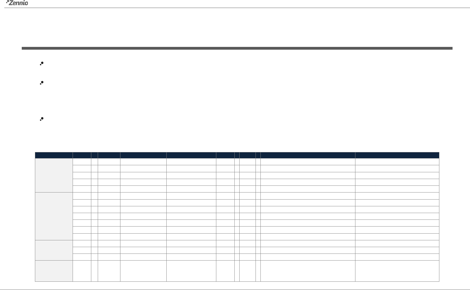
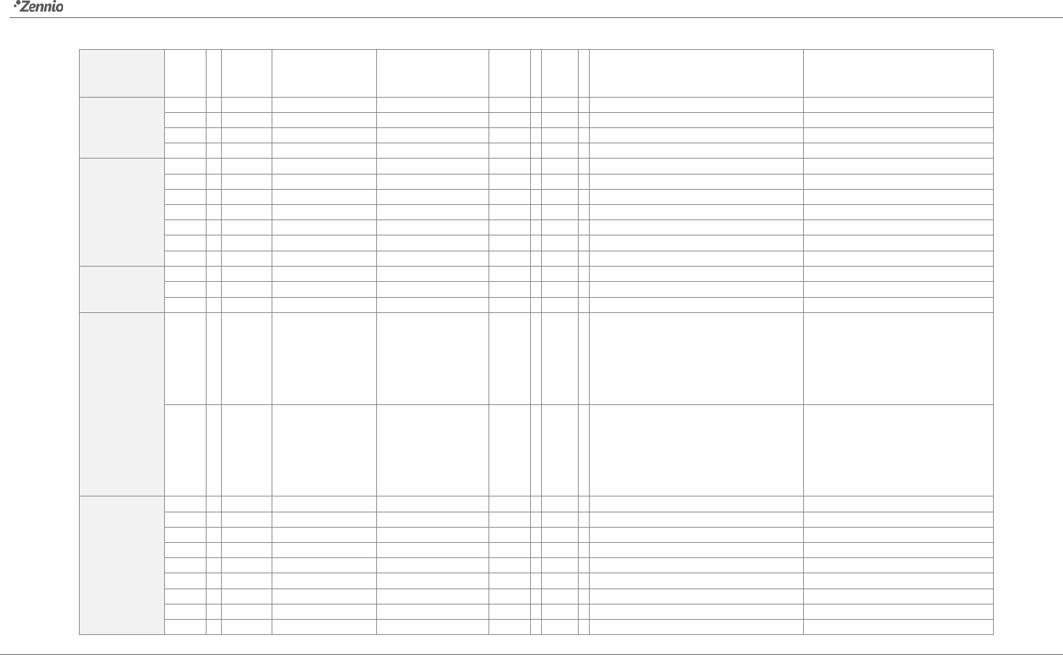
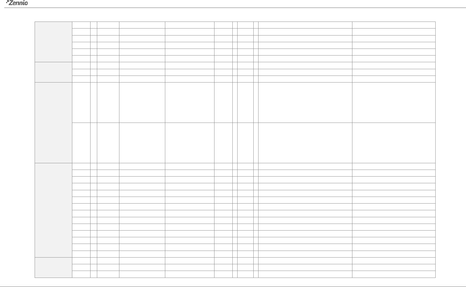
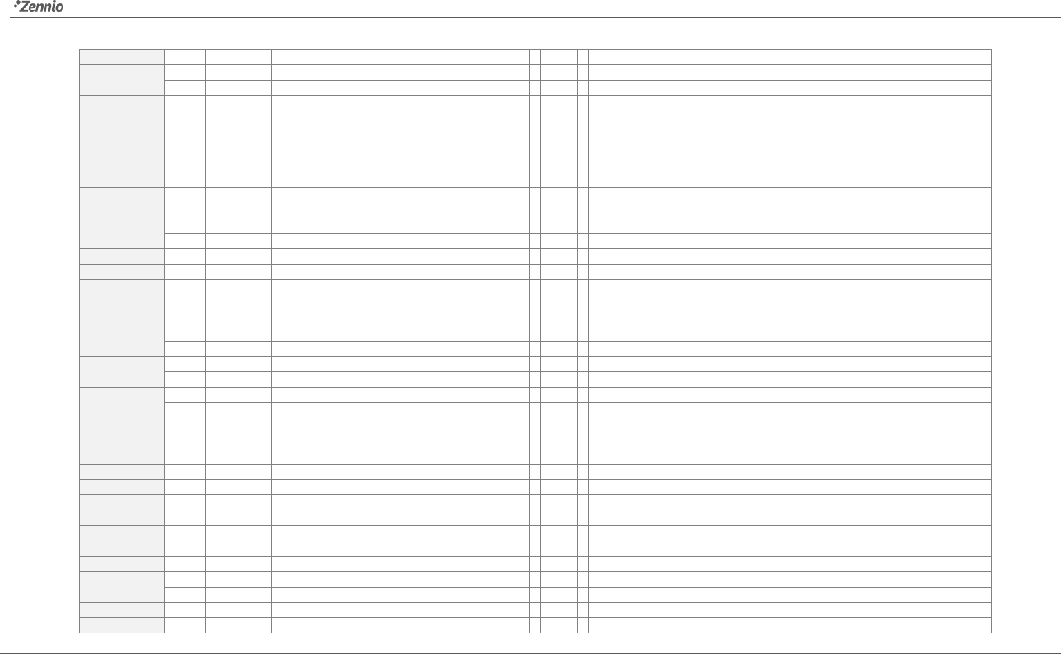
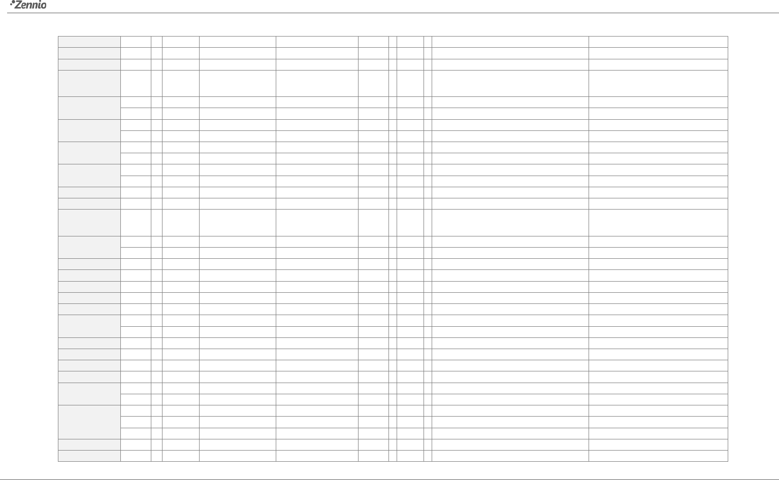
“Functional range” shows the values that, with independence of any other values permitted by the bus according to the object size, may be of any use or have a particular meaning because of the
specifications or restrictions from both the KNX standard or the application program itself.
1st boot” shows the cases where an object is assigned a certain value by the application program after a device download or a full reset. In case the value of such assignment can be
parameterised, is shown in column “P”. Objects showing a hyphen (-) are not assigned a particular value and therefore can be assumed to be initialised with the value “0”, or with the
corresponding updated value in case they depend on an external element (sensors, etc.). Moreover, if the object is sent (or is there an option to send it) to the bus (write or read requests) after a
download or a device reset from ETS, the marks (W) or (R) will be shown, respectively for transmissions or read requests.
Reboot” shows the cases where an object is assigned a certain value by the application program after a bus power failure. In case the value of such assignment can be parameterised, is shown
in column “P”. Objects showing a hyphen (-) are not assigned a particular value and therefore can be assumed to maintain their previous value after the failure, or with the corresponding updated
value in case they depend on external elements. Moreover, if the object is sent (or is there an option to send it) to the bus (write or read requests) after a bus failure, the marks (W) or (R) will be
shown, respectively for transmissions or read requests.
Number
Size
I/O
Flags
Data Type (DPT)
Functional Range
1st boot
P
Reboot
P
Name
Function
0, 1, 2, 3, 4, 5
1 Bit
I/O
C - R W U
DPT_Switch
0/1
-
-
[Ind x] Binary Indicator
1-bit generic indicator
1 Byte
I/O
C - R W U
DPT_Value_1_Ucount
0 - 255
-
-
[Ind x] Enum Indicator
1-byte enumeration
2 Bytes
I/O
C - R W U
9.xxx
-671088.64 670760.96
-
-
[Ind x] Float Indicator
2-byte float value
1 Byte
I/O
C - R W U
DPT_Value_1_Ucount
0 - 255
-
-
[Ind x] 1-byte Indicator
1-byte generic indicator
1 Byte
I/O
C - R W U
DPT_Scaling
0% - 100%
-
-
[Ind x] Scaling Indicator
Scaling value
6, 14, 22, 30
1 Bit
I/O
C T R W U
DPT_Switch
0/1
-
-
[P1][Bx] Binary Control
1-bit generic control
1 Bit
O
C T R - -
DPT_Switch
0/1
-
-
[P1][Bx] Binary Control: Hold
1-bit generic control
1 Bit
I/O
C T R W U
DPT_Switch
0/1
-
-
[P1][Bxy] Binary Control
1-bit generic control
1 Bit
I/O
C T R W U
DPT_Switch
0/1
-
-
[P1][Bxy] Light On/Off
0=Off; 1=On
1 Bit
O
C T R - -
DPT_UpDown
0/1
-
-
[P1][Bxy] Move Shutter
0=Up; 1=Down
1 Bit
I/O
C T R W U
DPT_Switch
0/1
-
-
[P1][Bx] Light On/Off
0=Off;1=On
1 Bit
O
C T R - -
DPT_Switch
0/1
-
-
[P1][Bx] Timed switch control
1-bit generic control
7, 15, 23, 31
1 Bit
O
C T R - -
DPT_Switch
0/1
-
-
[P1][Bx] Binary Control: Release
1-bit generic control
1 Bit
O
C T R - -
DPT_Step
0/1
-
-
[P1][Bxy] Stop Shutter
0 or 1 -> Stop
1 Bit
I
C - - W -
DPT_Enable
0/1
-
-
[P1][Bx] Timer enable
0=Disable; 1=Enable
8, 16, 24, 32 4 Bit O
C T R - -
DPT_Control_Dimming
0x0 (Stop)
0x1 (Dec.by 100%)
0x2 (Dec.by 50%)
0x3 (Dec.by 25%)
- -
[P1][Bxy] Light Dimming 4-bit dimming control
Roll-ZAS
http://www.zennio.com Technical Support: http://zennioenglish.zendesk.com
46
0x4 (Dec.by 12%)
0x5 (Dec.by 6%)
0x6 (Dec.by 3%)
0x7 (Dec.by 1%)
0x8 (Stop)
0x9 (Inc.by 100%)
0xA (Inc.by 50%)
0xB (Inc.by 25%)
0xC (Inc.by 12%)
0xD (Inc.by 6%)
0xE (Inc.by 3%)
0xF (Inc.by 1%)
4 Bit O
C T R - -
DPT_Control_Dimming
0x0 (Stop)
0x1 (Dec.by 100%)
0x7 (Dec.by 1%)
0x8 (Stop)
0x9 (Inc.by 100%)
0xF (Inc.by 1%)
-
-
[P1][Bx] Light Dimming 4-bit dimming control
9, 17, 25, 33
1 Byte
O
C T R - -
DPT_Value_1_Ucount
0 - 255
-
-
[P1][Bx] 1-byte value
0-255
2 Bytes
O
C T R - -
DPT_Value_2_Ucount
0 - 65535
-
-
[P1][Bx] 2-byte value (unsigned int)
0-65535
2 Bytes
O
C T R - -
9.xxx
-671088.64 - 670760.96
-
-
[P1][Bx] 2-byte value (float)
0-120.0
1 Byte
I/O
C T R W U
DPT_Scaling
0% - 100%
Min
-
[P1][Bxy] Scaling
0-100%
1 Byte
I/O
C T R W U
DPT_Value_1_Ucount
0 - 255
Min
-
[P1][Bxy] 1-byte counter
0-255
1 Byte
O
C T R W U
DPT_Value_1_Ucount
0 - 255
Min
-
[P1][Bxy] Enum Control
0-255
2 Bytes
I/O
C T R W U
DPT_Value_Temp
-273.00 - 670760.00
25.00
-
[P1][Bxy] Temperature Control
-20-95ºC
1 Byte
I
C T - W U
DPT_Scaling
0% - 100%
Min
-
[P1][Bxy] Light Indicator
0%=Off; 100%=On
1 Byte
I
C T - W U
DPT_Scaling
0% - 100%
Min
-
[P1][Bxy] Shutter Position
0%=Top; 100%=Bottom
1 Byte
I
C T - W U
DPT_Scaling
0% - 100%
-
-
[P1][Bx] Light Indicator
0%=Off;100%=On
1 Byte
I
C T - W U
DPT_Value_1_Ucount
0 - 255
-
-
[P1][Bxy] 1-byte Indicator
0-255
1 Byte
I
C T - W U
DPT_Scaling
0% - 100%
-
-
[P1][Bxy] Scaling Indicator
0-100%
2 Bytes
I
C T - W U
DPT_Value_2_Ucount
0 - 65535
-
-
[P1][Bxy] 2-byte Indicator
0-65535
2 Bytes
I
C T - W U
DPT_Value_Temp
-273.00 - 670760.00
-
-
[P1][Bxy] Temperature Indicator
-20-95ºC
10, 18, 26, 34
1 Bit
I/O
C T R W U
DPT_Switch
0/1
-
-
[P1][Bx] Binary Control
1-bit generic control
1 Bit
O
C T R - -
DPT_Switch
0/1
-
-
[P1][Bx] Binary Control: Hold
1-bit generic control
1 Bit
I/O
C T R W U
DPT_Switch
0/1
-
-
[P1][Bx] Light On/Off
0=Off;1=On
1 Bit
O
C T R - -
DPT_Switch
0/1
-
-
[P1][Bx] Timed switch control
1-bit generic control
11, 19, 27, 35
1 Bit
O
C T R - -
DPT_Switch
0/1
-
-
[P1][Bx] Binary Control: Release
1-bit generic control
1 Bit
I
C - - W -
DPT_Enable
0/1
-
-
[P1][Bx] Timer enable
0=Disable; 1=Enable
12, 20, 28, 36 4 Bit O
C T R - -
DPT_Control_Dimming
0x0 (Stop)
0x1 (Dec.by 100%)
0x7 (Dec.by 1%)
-
-
[P1][Bx] Light Dimming 4-bit dimming control
Roll-ZAS
http://www.zennio.com Technical Support: http://zennioenglish.zendesk.com
47
0x8 (Stop)
0x9 (Inc.by 100%)
0xF (Inc.by 1%)
13, 21, 29, 37
1 Byte
O
C T R - -
DPT_Value_1_Ucount
0 - 255
-
-
[P1][Bx] 1-byte value
0-255
2 Bytes
O
C T R - -
DPT_Value_2_Ucount
0 - 65535
-
-
[P1][Bx] 2-byte value (unsigned int)
0-65535
2 Bytes
O
C T R - -
9.xxx
-671088.64 - 670760.96
-
-
[P1][Bx] 2-byte value (float)
0-120.0
1 Byte
I
C - - W -
DPT_Scaling
0% - 100%
-
-
[P1][Bx] Light Indicator
0%=Off;100%=On
38, 46, 54, 62
1 Bit
O
C T R - -
DPT_Switch
0/1
-
-
[P2][Bx] Binary Control: Hold
1-bit generic control
1 Bit
I/O
C T R W U
DPT_Switch
0/1
-
-
[P2][Bx] Binary Control
1-bit generic control
1 Bit
I/O
C T R W U
DPT_Switch
0/1
-
-
[P2][Bxy] Binary Control
1-bit generic control
1 Bit
I/O
C T R W U
DPT_Switch
0/1
-
-
[P2][Bxy] Light On/Off
0=Off; 1=On
1 Bit
O
C T R - -
DPT_UpDown
0/1
-
-
[P2][Bxy] Move Shutter
0=Up; 1=Down
1 Bit
I/O
C T R W U
DPT_Switch
0/1
-
-
[P2][Bx] Light On/Off
0=Off;1=On
1 Bit
O
C T R - -
DPT_Switch
0/1
-
-
[P2][Bx] Timed switch control
1-bit generic control
39, 47, 55, 63
1 Bit
O
C T R - -
DPT_Switch
0/1
-
-
[P2][Bx] Binary Control: Release
1-bit generic control
1 Bit
O
C T R - -
DPT_Step
0/1
-
-
[P2][Bxy] Stop Shutter
0 or 1 -> Stop
1 Bit
I
C - - W -
DPT_Enable
0/1
-
-
[P2][Bx] Timer enable
0=Disable; 1=Enable
40, 48, 56, 64
4 Bit O
C T R - -
DPT_Control_Dimming
0x0 (Stop)
0x1 (Dec.by 100%)
0x7 (Dec.by 1%)
0x8 (Stop)
0x9 (Inc.by 100%)
0xF (Inc.by 1%)
-
-
[P2][Bxy] Light Dimming 4-bit dimming control
4 Bit O
C T R - -
DPT_Control_Dimming
0x0 (Stop)
0x1 (Dec.by 100%)
0x7 (Dec.by 1%)
0x8 (Stop)
0x9 (Inc.by 100%)
0xF (Inc.by 1%)
-
-
[P2][Bx] Light Dimming 4-bit dimming control
41, 49, 57, 65
2 Bytes
O
C T R - -
9.xxx
-671088.64 - 670760.96
-
-
[P2][Bx] 2-byte value (float)
0-120.0
2 Bytes
O
C T R - -
DPT_Value_2_Ucount
0 - 65535
-
-
[P2][Bx] 2-byte value (unsigned int)
0-65535
1 Byte
O
C T R - -
DPT_Value_1_Ucount
0 - 255
-
-
[P2][Bx] 1-byte value
0-255
1 Byte
I/O
C T R W U
DPT_Scaling
0% - 100%
-
-
[P2][Bxy] Scaling
0-100%
1 Byte
I/O
C T R W U
DPT_Value_1_Ucount
0 - 255
-
-
[P2][Bxy] 1-byte counter
0-255
1 Byte
O
C T R W U
DPT_Value_1_Ucount
0 - 255
-
-
[P2][Bxy] Enum Control
0-255
2 Bytes
I/O
C T R W U
DPT_Value_Temp
-273.00 - 670760.00
-
-
[P2][Bxy] Temperature Control
-20-95ºC
1 Byte
I
C T - W U
DPT_Scaling
0% - 100%
-
-
[P2][Bxy] Light Indicator
0%=Off; 100%=On
1 Byte
I
C T - W U
DPT_Scaling
0% - 100%
-
-
[P2][Bxy] Shutter Position
0%=Top; 100%=Bottom
Roll-ZAS
http://www.zennio.com Technical Support: http://zennioenglish.zendesk.com
48
1 Byte
I
C - - W -
DPT_Scaling
0% - 100%
-
-
[P2][Bx] Light Indicator
0%=Off;100%=On
1 Byte
I
C T - W U
DPT_Scaling
0% - 100%
-
-
[P2][Bxy] Scaling Indicator
0-100%
1 Byte
I
C T - W U
DPT_Value_1_Ucount
0 - 255
-
-
[P2][Bxy] 1-byte Indicator
0-255
2 Bytes
I
C T - W U
DPT_Value_2_Ucount
0 - 65535
-
-
[P2][Bxy] 2-byte Indicator
0-65535
2 Bytes
I
C T - W U
DPT_Value_Temp
-273.00 - 670760.00
-
-
[P2][Bxy] Temperature Indicator
-20-95ºC
42, 50, 58, 66
1 Bit
I/O
C T R W U
DPT_Switch
0/1
-
-
[P2][Bx] Binary Control
1-bit generic control
1 Bit
O
C T R - -
DPT_Switch
0/1
-
-
[P2][Bx] Binary Control: Hold
1-bit generic control
1 Bit
I/O
C T R W U
DPT_Switch
0/1
-
-
[P2][Bx] Light On/Off
0=Off;1=On
1 Bit
O
C T R - -
DPT_Switch
0/1
-
-
[P2][Bx] Timed switch control
1-bit generic control
43, 51, 59, 67
1 Bit
O
C T R - -
DPT_Switch
0/1
-
-
[P2][Bx] Binary Control: Release
1-bit generic control
1 Bit
I
C - - W -
DPT_Enable
0/1
-
-
[P2][Bx] Timer enable
0=Disable; 1=Enable
44, 52, 60, 68 4 Bit O
C T R - -
DPT_Control_Dimming
0x0 (Stop)
0x1 (Dec.by 100%)
0x7 (Dec.by 1%)
0x8 (Stop)
0x9 (Inc.by 100%)
0xF (Inc.by 1%)
-
-
[P2][Bx] Light Dimming 4-bit dimming control
45, 53, 61, 69
2 Bytes
O
C T R - -
9.xxx
-671088.64 - 670760.96
-
-
[P2][Bx] 2-byte value (float)
0-120.0
2 Bytes
O
C T R - -
DPT_Value_2_Ucount
0 - 65535
-
-
[P2][Bx] 2-byte value (unsigned int)
0-65535
1 Byte
O
C T R - -
DPT_Value_1_Ucount
0 - 255
-
-
[P2][Bx] 1-byte value
0-255
1 Byte
I
C - - W -
DPT_Scaling
0% - 100%
-
-
[P2][Bx] Light Indicator
0%=Off;100%=On
70, 78, 86, 94
1 Bit
I/O
C T R W U
DPT_Switch
0/1
-
-
[P3][Bx] Binary Control
1-bit generic control
1 Bit
O
C T R - -
DPT_Switch
0/1
-
-
[P3][Bx] Binary Control: Hold
1-bit generic control
1 Bit
I/O
C T R W U
DPT_Switch
0/1
-
-
[P3][Bxy] Binary Control
1-bit generic control
1 Bit
I/O
C T R W U
DPT_Switch
0/1
-
-
[P3][Bxy] Light On/Off
0=Off; 1=On
1 Bit
O
C T R - -
DPT_UpDown
0/1
-
-
[P3][Bxy] Move Shutter
0=Up; 1=Down
1 Bit
I/O
C T R W U
DPT_Switch
0/1
-
-
[P3][Bx] Light On/Off
0=Off;1=On
1 Bit
O
C T R - -
DPT_Switch
0/1
-
-
[P3][Bx] Timed switch control
1-bit generic control
71, 79, 87, 95
1 Bit
O
C T R - -
DPT_Switch
0/1
-
-
[P3][Bx] Binary Control: Release
1-bit generic control
1 Bit
O
C T R - -
DPT_Step
0/1
-
-
[P3][Bxy] Stop Shutter
0 or 1 -> Stop
1 Bit
I
C - - W -
DPT_Enable
0/1
-
-
[P3][Bx] Timer enable
0=Disable; 1=Enable
72, 80, 88, 96
4 Bit O
C T R - -
DPT_Control_Dimming
0x0 (Stop)
0x1 (Dec.by 100%)
0x7 (Dec.by 1%)
0x8 (Stop)
0x9 (Inc.by 100%)
0xF (Inc.by 1%)
-
-
[P3][Bxy] Light Dimming 4-bit dimming control
4 Bit
O
C T R - -
DPT_Control_Dimming
0x0 (Stop)
-
-
[P3][Bx] Light Dimming
4-bit dimming control
Roll-ZAS
http://www.zennio.com Technical Support: http://zennioenglish.zendesk.com
49
0x1 (Dec.by 100%)
0x7 (Dec.by 1%)
0x8 (Stop)
0x9 (Inc.by 100%)
0xF (Inc.by 1%)
73, 81, 89, 97
1 Byte
O
C T R - -
DPT_Value_1_Ucount
0 - 255
-
-
[P3][Bx] 1-byte value
0-255
2 Bytes
O
C T R - -
DPT_Value_2_Ucount
0 - 65535
-
-
[P3][Bx] 2-byte value (unsigned int)
0-65535
2 Bytes
O
C T R - -
9.xxx
-671088.64 - 670760.96
-
-
[P3][Bx] 2-byte value (float)
0-120.0
1 Byte
I
C T - W U
DPT_Scaling
0% - 100%
-
-
[P3][Bxy] Light Indicator
0%=Off; 100%=On
1 Byte
I
C T - W U
DPT_Scaling
0% - 100%
-
-
[P3][Bxy] Shutter Position
0%=Top; 100%=Bottom
1 Byte
I/O
C T R W U
DPT_Scaling
0% - 100%
-
-
[P3][Bxy] Scaling
0-100%
1 Byte
I/O
C T R W U
DPT_Value_1_Ucount
0 - 255
-
-
[P3][Bxy] 1-byte counter
0-255
1 Byte
O
C T R W U
DPT_Value_1_Ucount
0 - 255
-
-
[P3][Bxy] Enum Control
0-255
2 Bytes
I/O
C T R W U
DPT_Value_Temp
-273.00 - 670760.00
-
-
[P3][Bxy] Temperature Control
-20-95ºC
1 Byte
I
C - - W -
DPT_Scaling
0% - 100%
-
-
[P3][Bx] Light Indicator
0%=Off;100%=On
1 Byte
I
C T - W U
DPT_Scaling
0% - 100%
-
-
[P3][Bxy] Scaling Indicator
0-100%
1 Byte
I
C T - W U
DPT_Value_1_Ucount
0 - 255
-
-
[P3][Bxy] 1-byte Indicator
0-255
2 Bytes
I
C T - W U
DPT_Value_2_Ucount
0 - 65535
-
-
[P3][Bxy] 2-byte Indicator
0-65535
2 Bytes
I
C T - W U
DPT_Value_Temp
-273.00 - 670760.00
-
-
[P3][Bxy] Temperature Indicator
-20-95ºC
74, 82, 90, 98
1 Bit
O
C T R - -
DPT_Switch
0/1
-
-
[P3][Bx] Binary Control: Hold
1-bit generic control
1 Bit
I/O
C T R W U
DPT_Switch
0/1
-
-
[P3][Bx] Binary Control
1-bit generic control
1 Bit
I/O
C T R W U
DPT_Switch
0/1
-
-
[P3][Bx] Light On/Off
0=Off;1=On
1 Bit
O
C T R - -
DPT_Switch
0/1
-
-
[P3][Bx] Timed switch control
1-bit generic control
75, 83, 91, 99
1 Bit
O
C T R - -
DPT_Switch
0/1
-
-
[P3][Bx] Binary Control: Release
1-bit generic control
1 Bit
I
C - - W -
DPT_Enable
0/1
-
-
[P3][Bx] Timer enable
0=Disable; 1=Enable
76, 84, 92, 100 4 Bit O
C T R - -
DPT_Control_Dimming
0x0 (Stop)
0x1 (Dec.by 100%)
0x7 (Dec.by 1%)
0x8 (Stop)
0x9 (Inc.by 100%)
0xF (Inc.by 1%)
-
-
[P3][Bx] Light Dimming 4-bit dimming control
77, 85, 93, 101
1 Byte
O
C T R - -
DPT_Value_1_Ucount
0 - 255
-
-
[P3][Bx] 1-byte value
0-255
2 Bytes
O
C T R - -
DPT_Value_2_Ucount
0 - 65535
-
-
[P3][Bx] 2-byte value (unsigned int)
0-65535
2 Bytes
O
C T R - -
9.xxx
-671088.64 - 670760.96
-
-
[P3][Bx] 2-byte value (float)
0-120.0
1 Byte
I
C - - W -
DPT_Scaling
0% - 100%
-
-
[P3][Bx] Light Indicator
0%=Off;100%=On
102, 110, 118, 126
1 Bit
O
C T R - -
DPT_Switch
0/1
-
-
[P4][Bx] Binary Control: Hold
1-bit generic control
1 Bit
I/O
C T R W U
DPT_Switch
0/1
-
-
[P4][Bx] Binary Control
1-bit generic control
Roll-ZAS
http://www.zennio.com Technical Support: http://zennioenglish.zendesk.com
50
1 Bit
I/O
C T R W U
DPT_Switch
0/1
-
-
[P4][Bxy] Binary Control
1-bit generic control
1 Bit
I/O
C T R W U
DPT_Switch
0/1
-
-
[P4][Bxy] Light On/Off
0=Off; 1=On
1 Bit
O
C T R - -
DPT_UpDown
0/1
-
-
[P4][Bxy] Move Shutter
0=Up; 1=Down
1 Bit
O
C T R - -
DPT_Switch
0/1
-
-
[P4][Bx] Light On/Off
0=Off;1=On
1 Bit
O
C T R - -
DPT_Step
0/1
-
-
[P4][Bxy] Binary Control
0=Backward; 1=Forward
1 Bit
O
C T R - -
DPT_Switch
0/1
-
-
[P4][Bx] Timed switch control
1-bit generic control
103, 111, 119, 127
1 Bit
O
C T R - -
DPT_Switch
0/1
-
-
[P4][Bx] Binary Control: Release
1-bit generic control
1 Bit
O
C T R - -
DPT_Step
0/1
-
-
[P4][Bxy] Stop Shutter
0 or 1 -> Stop
1 Bit
I
C - - W -
DPT_Enable
0/1
-
-
[P4][Bx] Timer enable
0=Disable; 1=Enable
104, 112, 120, 128
4 Bit O
C T R - -
DPT_Control_Dimming
0x0 (Stop)
0x1 (Dec.by 100%)
0x7 (Dec.by 1%)
0x8 (Stop)
0x9 (Inc.by 100%)
0xF (Inc.by 1%)
-
-
[P4][Bxy] Light Dimming 4-bit dimming control
4 Bit O
C T R - -
DPT_Control_Dimming
0x0 (Stop)
0x1 (Dec.by 100%)
0x7 (Dec.by 1%)
0x8 (Stop)
0x9 (Inc.by 100%)
0xF (Inc.by 1%)
-
-
[P4][Bx] Light Dimming 4-bit dimming control
105, 113, 121, 129
1 Byte
O
C T R - -
DPT_Value_1_Ucount
0 - 255
-
-
[P4][Bx] 1-byte value
0-255
2 Bytes
O
C T R - -
DPT_Value_2_Ucount
0 - 65535
-
-
[P4][Bx] 2-byte value (unsigned int)
0-65535
2 Bytes
O
C T R - -
9.xxx
-671088.64 - 670760.96
-
-
[P4][Bx] 2-byte value (float)
0-120.0
1 Byte
I
C T - W U
DPT_Scaling
0% - 100%
-
-
[P4][Bxy] Light Indicator
0%=Off; 100%=On
1 Byte
I
C T - W U
DPT_Scaling
0% - 100%
-
-
[P4][Bxy] Shutter Position
0%=Top; 100%=Bottom
1 Byte
I/O
C T R W U
DPT_Scaling
0% - 100%
-
-
[P4][Bxy] Scaling
0-100%
1 Byte
I/O
C T R W U
DPT_Value_1_Ucount
0 - 255
-
-
[P4][Bxy] 1-byte counter
0-255
1 Byte
O
C T R W U
DPT_Value_1_Ucount
0 - 255
-
-
[P4][Bxy] Enum Control
0-255
2 Bytes
I/O
C T R W U
DPT_Value_Temp
-273.00 - 670760.00
-
-
[P4][Bxy] Temperature Control
-20-95ºC
1 Byte
I
C - - W -
DPT_Scaling
0% - 100%
-
-
[P4][Bx] Light Indicator
0%=Off;100%=On
1 Byte
I
C T - W U
DPT_Scaling
0% - 100%
-
-
[P4][Bxy] Scaling Indicator
0-100%
1 Byte
I
C T - W U
DPT_Value_1_Ucount
0 - 255
-
-
[P4][Bxy] 1-byte Indicator
0-255
2 Bytes
I
C T - W U
DPT_Value_2_Ucount
0 - 65535
-
-
[P4][Bxy] 2-byte Indicator
0-65535
2 Bytes
I
C T - W U
DPT_Value_Temp
-273.00 - 670760.00
-
-
[P4][Bxy] Temperature Indicator
-20-95ºC
106, 114, 122, 130
1 Bit
O
C T R - -
DPT_Switch
0/1
-
-
[P4][Bx] Binary Control: Hold
1-bit generic control
1 Bit
I/O
C T R W U
DPT_Switch
0/1
-
-
[P4][Bx] Binary Control
1-bit generic control
1 Bit
O
C T R - -
DPT_Switch
0/1
-
-
[P4][Bx] Light On/Off
0=Off;1=On
Roll-ZAS
http://www.zennio.com Technical Support: http://zennioenglish.zendesk.com
51
1 Bit
O
C T R - -
DPT_Switch
0/1
-
-
[P4][Bx] Timed switch control
1-bit generic control
107, 115, 123, 131
1 Bit
O
C T R - -
DPT_Switch
0/1
-
-
[P4][Bx] Binary Control: Release
1-bit generic control
1 Bit
I
C - - W -
DPT_Enable
0/1
-
-
[P4][Bx] Timer enable
0=Disable; 1=Enable
108, 116, 124, 132
4 Bit O
C T R - -
DPT_Control_Dimming
0x0 (Stop)
0x1 (Dec.by 100%)
0x7 (Dec.by 1%)
0x8 (Stop)
0x9 (Inc.by 100%)
0xF (Inc.by 1%)
-
-
[P4][Bx] Light Dimming 4-bit dimming control
109, 117, 125, 133
2 Bytes
O
C T R - -
9.xxx
-671088.64 - 670760.96
-
-
[P4][Bx] 2-byte value (float)
0-120.0
1 Byte
O
C T R - -
DPT_Value_1_Ucount
0 - 255
-
-
[P4][Bx] 1-byte value
0-255
2 Bytes
O
C T R - -
DPT_Value_2_Ucount
0 - 65535
-
-
[P4][Bx] 2-byte value (unsigned int)
0-65535
1 Byte
I
C - - W -
DPT_Scaling
0% - 100%
-
-
[P4][Bx] Light Indicator
0%=Off;100%=On
134
3 Bytes
I/O
C T R W U
DPT_TimeOfDay
00:00:00 - 23:59:59
-
-
[General] Time
Current Time
135
1 Byte
I
C - - W -
DPT_SceneControl
0-63; 128-191
-
-
[General] Scene: receive
0-63 (Run Scene 1-64)
136
1 Byte
C T - - -
DPT_SceneControl
0-63; 128-191
-
-
[General] Scene: send
0-63 (Run or Save Scene 1-64)
137
1 Bit
I
C - - W -
DPT_Switch
0/1
-
-
[General] Display Lighting 1
1=Light the Display;0=NoAction
1 Bit
I
C - - W -
DPT_Switch
0/1
-
-
[General] Display Lighting 1
0=Light the Display;1=NoAction
138
1 Bit
I
C - - W -
DPT_Switch
0/1
-
-
[General] Display Lighting 2
1=Light the Display;0=NoAction
1 Bit
I
C - - W -
DPT_Switch
0/1
-
-
[General] Display Lighting 2
0=Light the Display;1=NoAction
139
1 Bit
I
C - - W -
DPT_Trigger
0/1
-
-
[General] Touch Lock
0=Lock; 1=Nothing
1 Bit
I
C - - W -
DPT_Trigger
0/1
-
-
[General] Touch Lock
1=Lock; 0=Nothing
140
1 Bit
I
C - - W -
DPT_Trigger
0/1
-
-
[General] Touch Unlock
0=Unlock; 1=Nothing
1 Bit
I
C - - W -
DPT_Trigger
0/1
-
-
[General] Touch Unlock
1=Unlock; 0=Nothing
141
1 Bit
C T - - -
DPT_Switch
0/1
-
-
[General] Welcome Object
1-bit generic control
142
2 Bytes
I
C - - W -
DPT_Value_Temp
-273.00 - 670760.00
-
-
[General] Screensaver Temperature
Temp. Shown in Screensaver
143, 144
1 Bit
I
C - - W -
DPT_Switch
0/1
-
-
[Ix] Lock
1=Input Disabled; 0=Input Free
145, 146
1 Bit
I
C T - W -
DPT_Switch
0/1
- W
- W
[Ix] Edge
Edge -> Sending of "0" or "1"
147
1 Bit
I
C - - W -
DPT_Switch
0/1
-
-
[Sim] Presence Simulation
0=Disabled;1=Enabled
148
1 Bit
O
C T R - -
DPT_Switch
0/1
-
-
[Sim] Simulation Channel
0=Off; 1=On
149
1 Bit
C T - - -
DPT_Switch
0/1
-
-
[IR] F1
1-bit generic control
150
1 Bit
C T - - -
DPT_Switch
0/1
-
-
[IR] F2
1-bit generic control
151, 152
2 Bytes
O
C T R - -
DPT_Value_Temp
-273.00 - 670760.00
25.00
-
[Ix] Current Temperature
Temperature sensor value
153
2 Bytes
O
C T R - -
DPT_Value_Temp
-273.00 - 670760.00
-
-
[Internal Sensor] Current Temperature
Temperature sensor value
154, 155
1 Bit
O
C T R - -
DPT_Switch
0/1
-
-
[Ix] Overcooling
1=Overcooling;0=No Overcooling
156
1 Bit
O
C T R - -
DPT_Switch
0/1
-
-
[Internal Sensor] Overcooling
1=Overcooling;0=No Overcooling
157, 158
1 Bit
O
C T R - -
DPT_Switch
0/1
-
-
[Ix] Overheating
1=Overheating;0=No Overheating
159
1 Bit
O
C T R - -
DPT_Switch
0/1
-
-
[Internal Sensor] Overheating
1=Overheating;0=No Overheating
Roll-ZAS
http://www.zennio.com Technical Support: http://zennioenglish.zendesk.com
52
160, 161
1 Bit
O
C T R - -
DPT_Switch
0/1
-
-
[Ix] Probe Error
1=Error;0=No Error
162, 164
2 Bytes
I
C - - W -
DPT_Value_Temp
-273.00 - 670760.00
25.00
-
[Tx] Temperature Source 1
External Sensor Measure
163, 165
2 Bytes
I
C - - W -
DPT_Value_Temp
-273.00 - 670760.00
25.00
-
[Tx] Temperature Source 2
External Sensor Measure
166, 167 1 Byte I
C - - W -
DPT_HVACMode
1=Comfort. 2=Standby
3=Economy
4=Protection
-
-
[Tx] Special Mode 1-byte HVAC Mode
168, 172
1 Bit
I
C - - W -
DPT_Trigger
0/1
-
-
[Tx] Special Mode: comfort
0=Nothing; 1=Trigger
1 Bit
I
C - - W -
DPT_Switch
0/1
-
-
[Tx] Special Mode: comfort
0=Off; 1=On
169, 173
1 Bit
I
C - - W -
DPT_Trigger
0/1
-
-
[Tx] Special Mode: standby
0=Nothing; 1=Trigger
1 Bit
I
C - - W -
DPT_Switch
0/1
-
-
[Tx] Special Mode: standby
0=Off; 1=On
170, 174
1 Bit
I
C - - W -
DPT_Trigger
0/1
-
-
[Tx] Special Mode: economy
0=Nothing; 1=Trigger
1 Bit
I
C - - W -
DPT_Switch
0/1
-
-
[Tx] Special Mode: economy
0=Off; 1=On
171, 175
1 Bit
I
C - - W -
DPT_Trigger
0/1
-
-
[Tx] Special Mode: protection
0=Nothing; 1=Trigger
1 Bit
I
C - - W -
DPT_Switch
0/1
-
-
[Tx] Special Mode: protection
0=Off; 1=On
176, 177
1 Bit
I
C - - W -
DPT_Window_Door
0/1
-
-
[Tx] Window Status (input)
0=Closed; 1=Open
178, 179
1 Bit
I
C - - W -
DPT_Trigger
0/1
-
-
[Tx] Comfort Prolongation
0=Nothing; 1=Timed Comfort
180, 181 1 Byte O
C T R - -
DPT_HVACMode
1=Comfort. 2=Standby
3=Economy
4=Protection
- W
- W
[Tx] Special Mode Status 1-byte HVAC Mode
182, 183
2 Bytes
I
C - - W -
DPT_Value_Temp
-273.00 - 670760.00
-
-
[Tx] Setpoint
Thermostat setpoint input
2 Bytes
I
C - - W -
DPT_Value_Temp
-273.00 - 670760.00
-
-
[Tx] Basic Setpoint
Reference setpoint
184, 185
1 Bit
I
C - - W -
DPT_Step
0/1
-
-
[Tx] Setpoint Step
0=-0.5ºC; 1=+0.5ºC
186, 187
2 Bytes
I
C - - W -
DPT_Value_Tempd
-670760.00 - 670760.00
-
-
[Tx] Setpoint Offset
Float offset value
188, 189
2 Bytes
O
C T R - -
DPT_Value_Temp
-273.00 - 670760.00
- W
- W
[Tx] Setpoint Status
Current setpoint
190, 191
2 Bytes
O
C T R - -
DPT_Value_Temp
-273.00 - 670760.00
- W
- W
[Tx] Basic Setpoint Status
Current basic setpoint
192, 193
2 Bytes
O
C T R - -
DPT_Value_Tempd
-670760.00 - 670760.00
- W
- W
[Tx] Setpoint Offset Status
Current setpoint offset
194, 195
1 Bit
I
C - - W -
DPT_Reset
0/1
-
-
[Tx] Setpoint Reset
Reset setpoint to default
1 Bit
I
C - - W -
DPT_Reset
0/1
-
-
[Tx] Offset Reset
Reset offset
196, 197
1 Bit
I
C - - W -
DPT_Heat_Cool
0/1
-
-
[Tx] Mode
0 = Cool; 1 = Heat
198, 199
1 Bit
O
C T R - -
DPT_Heat_Cool
0/1
- W
-
[Tx] Mode Status
0 = Cool; 1 = Heat
200, 201
1 Bit
I
C - - W -
DPT_Switch
0/1
-
-
[Tx] On/Off
0=Off; 1=On
202, 203
1 Bit
O
C T R - -
DPT_Switch
0/1
- W
- W
[Tx] On/Off Status
0=Off; 1=On
204, 206
1 Bit
O
C T R - -
DPT_Switch
0/1
- W
- W
[Tx] Control Variable (Cool)
2-Point Control
1 Bit
O
C T R - -
DPT_Switch
0/1
- W
- W
[Tx] Control Variable (Cool)
PI Control (PWM)
205, 207
1 Bit
O
C T R - -
DPT_Switch
0/1
- W
- W
[Tx] Control Variable (Heat)
2-Point Control
1 Bit
O
C T R - -
DPT_Switch
0/1
- W
- W
[Tx] Control Variable (Heat)
PI Control (PWM)
208, 210
1 Byte
O
C T R - -
DPT_Scaling
0% - 100%
- W
- W
[Tx] Control Variable (Cool)
PI Control (Continuous)
209, 211
1 Byte
O
C T R - -
DPT_Scaling
0% - 100%
- W
- W
[Tx] Control Variable (Heat)
PI Control (Continuous)
212, 214
1 Bit
O
C T R - -
DPT_Switch
0/1
- W
- W
[Tx] Additional Cool
Temp >= (Setpoint+Band) => "1"
Roll-ZAS
http://www.zennio.com Technical Support: http://zennioenglish.zendesk.com
53
213, 215
1 Bit
O
C T R - -
DPT_Switch
0/1
- W
- W
[Tx] Additional Heat
Temp <= (Setpoint-Band) => "1"
216, 218
1 Bit
O
C T R - -
DPT_Alarm
0/1
-
-
[Ix] Short Circuit
1=Short Circuit;0=No Short Cir
217, 219
1 Bit
O
C T R - -
DPT_Alarm
0/1
-
-
[Ix] Open Circuit
1=Open Circuit;0=No Open Circ.
220
1 Byte
O
C T R - -
DPT_Scaling
0% - 100%
-
-
[I1] Luminosity Level
Luminosity on Input 1
221
1 Byte
O
C T R - -
DPT_Scaling
0% - 100%
-
-
[I2] Luminosity Level
Luminosity on Input 2
222, 223
1 Bit
I
C - - W -
DPT_Enable
0/1
-
-
[I1][Ch.x] Channel enabling
1=Enable; 0=Disable
1 Bit
I
C - - W -
DPT_Enable
0/1
-
-
[I1][Ch.x] Channel lock
1=Lock; 0=Unlock
224, 225
1 Bit
I
C - - W -
DPT_Enable
0/1
-
-
[I2][Ch.x] Channel enabling
1=Enable; 0=Disable
1 Bit
I
C - - W -
DPT_Enable
0/1
-
-
[I2][Ch.x] Channel lock
1=Lock; 0=Unlock
226, 227
1 Bit
C T - - -
DPT_Switch
0/1
-
-
[I1][Ch.x] Detection Status
According to parameters
228, 229
1 Bit
C T - - -
DPT_Switch
0/1
-
-
[I2][Ch.x] Detection Status
According to parameters
230, 231
1 Byte
I
C - - W -
DPT_SceneControl
0-63; 128-191
-
-
[I1][Ch.x] Scene Reception
0-63 (Run Scene 1-64)
232, 233
1 Byte
I
C - - W -
DPT_SceneControl
0-63; 128-191
-
-
[I2][Ch.x] Scene Reception
0-63 (Run Scene 1-64)
234, 235
1 Byte
C T - - -
DPT_SceneControl
0-63; 128-191
-
-
[I1][Ch.x] Scene Sending
0-63 (Send Scene 1-64)
236, 237
1 Byte
C T - - -
DPT_SceneControl
0-63; 128-191
-
-
[I2][Ch.x] Scene Sending
0-63 (Send Scene 1-64)
238 1 Byte O
C T R - -
DPT_HVACMode
1=Comfort. 2=Standby
3=Economy
4=Protection
-
-
[IR] Special mode 1-byte HVAC Mode
239
1 Bit
I
C - - W -
DPT_Trigger
0/1
-
-
[General] LED Blink
1=Blink LEDs; 0=Nothing
240
1 Bit
I
C - - W -
DPT_Trigger
0/1
-
-
[General] Buzzer
1=Beep; 0=Nothing
241, 242, 243, 244
14 Bytes
I
C - - W -
DPT_String_ASCII
-
-
-
[P4][Bxy] String Indicator
14-byte string
245
1 Bit
I
C - - W -
DPT_Enable
0/1
-
-
[General] Buzzer Enabling
1=Enabled; 0=Disabled
246
1 Bit
O
C T R W -
DPT_Switch
0/1
-
-
[General] Central Button
1-bit generic control
Join and send us your inquiries
about Zennio devices:
http://zennioenglish.zendesk.com
Zennio Avance y Tecnología O.L.
C/ Río Jarama, 132. Nave P-8.11
45007 Toledo (Spain).
Tel. +34 925 232 002.
Fax. +34 925 337 310.
www.zennio.com
info@zennio.com
3


Need help? Post your question in this forum.

Forumrules


Report abuse

Libble takes abuse of its services very seriously. We're committed to dealing with such abuse according to the laws in your country of residence. When you submit a report, we'll investigate it and take the appropriate action. We'll get back to you only if we require additional details or have more information to share.

Product:

For example, Anti-Semitic content, racist content, or material that could result in a violent physical act.

For example, a credit card number, a personal identification number, or an unlisted home address. Note that email addresses and full names are not considered private information.

Forumrules

To achieve meaningful questions, we apply the following rules:

Register

Register getting emails for Zennio Roll-ZAS Touch Controller at:


You will receive an email to register for one or both of the options.


Get your user manual by e-mail

Enter your email address to receive the manual of Zennio Roll-ZAS Touch Controller in the language / languages: English as an attachment in your email.

The manual is 0,99 mb in size.


You will receive the manual in your email within minutes. If you have not received an email, then probably have entered the wrong email address or your mailbox is too full. In addition, it may be that your ISP may have a maximum size for emails to receive.

Others manual(s) of Zennio Roll-ZAS Touch Controller

Zennio Roll-ZAS Touch Controller User Manual - German - 49 pages


The manual is sent by email. Check your email

If you have not received an email with the manual within fifteen minutes, it may be that you have a entered a wrong email address or that your ISP has set a maximum size to receive email that is smaller than the size of the manual.

The email address you have provided is not correct.

Please check the email address and correct it.

Your question is posted on this page

Would you like to receive an email when new answers and questions are posted? Please enter your email address.


Info