474217
19
Zoom out
Zoom in
Previous page
1/29
Next page
Zusatzfunktionen und Anschlüsse
18
Sicherungen
Beschriftung Stärke Beschreibung
Netz 1,6 A, träge Netzzuleitung AC 230 V
24V 1 A, träge Versorgungsausgang DC 24 V
Klemme 9 + 10
Warnl. 1 A, träge Warnlichtausgang DC 24 V
Klemme 11 + 12
Trafoanschluss
Klemme Bezeichnung Funktion
19 + 21 230V Netzzuleitung (Primärwicklung), braun
23 + 24 24V 24V-Eingang (Sekundärwicklung),
Zuleitung zur Steuerung, violett oder weiß
Antriebe anschließen
Klemme Bezeichnung Funktion
5 + 6 M1 1-flügelig: keine Funktion
2-flügelig: Anschluss für Motor-1
Der Motor muss sich an dem Torflügel
befinden, der sich als zweites öffnet, bzw.
an dem sich eine Anschlagleiste außen
befindet.
Klemme 5: Motorkabel braun
Klemme 6: Motorkabel blau
7 + 8 M2 1-flügelig: Anschluss für den Motor
2-flügelig: Anschluss für Motor-2
Der Motor muss sich an dem Torflügel
befinden, der sich als erstes öffnet, bzw.
an dem sich keine Anschlagleiste außen
befindet.
Klemme 7: Motorkabel braun
Klemme 8: Motorkabel blau
M1
M2
0V
24V
24V
Warnlicht
5
6
7
8
9
10
11
12
1
7
8
M1
M2
0V
24V
24V
Warnlicht
5
6
7
8
9
10
11
12
1
5
6
230 V
24 V
21
19
23
24
FUSE
N
K
T1A
Warnlicht
DIP
3
4
5
6
8
7
FUSE
5x20
T 1,6A
T 1A
N
e
t
z
24V
E
3
4
FUSE
5x20
FUSE
5x20
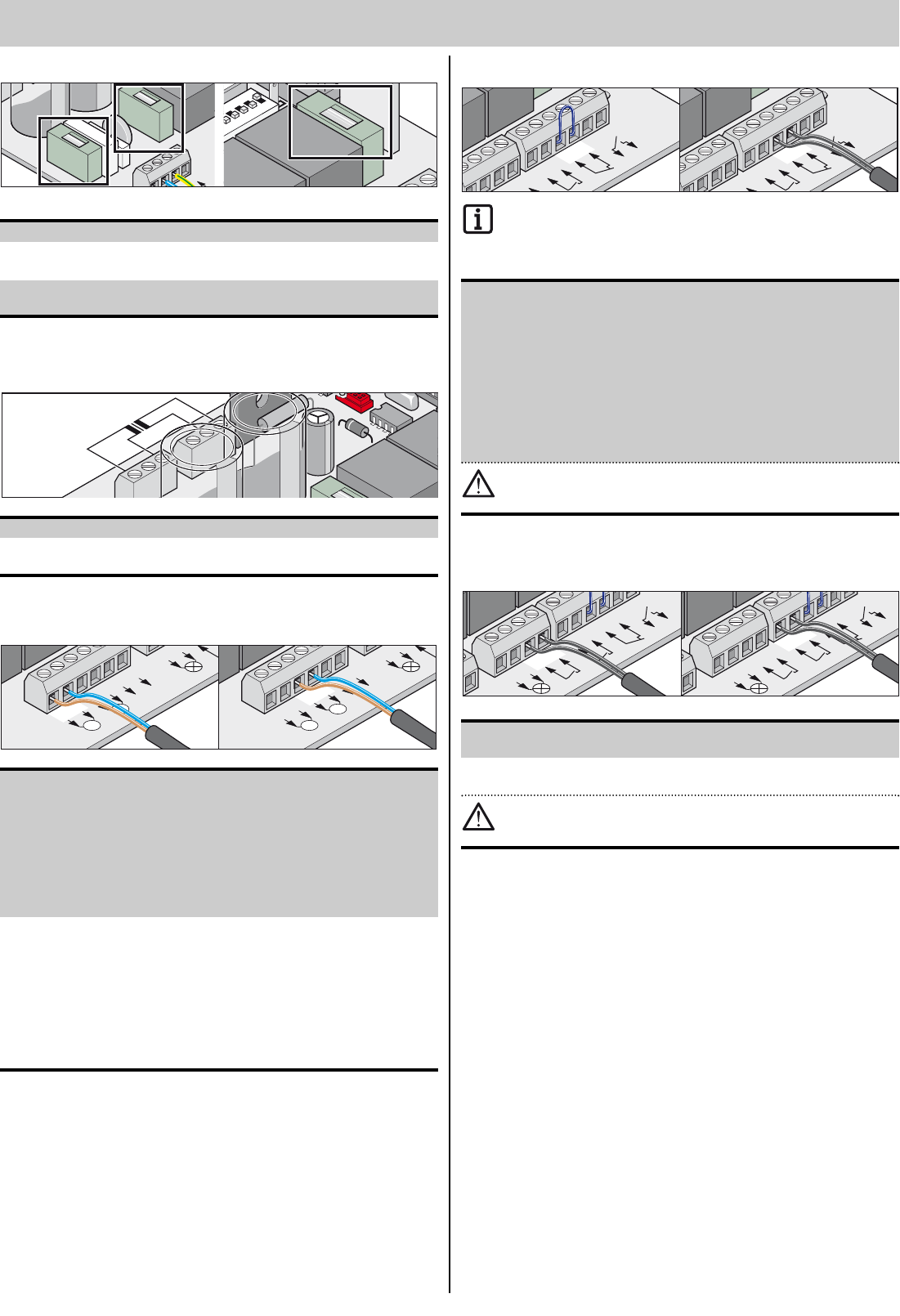
Sicherheitseinrichtung anschließen
Beim Betrieb mit Automatischem Zulauf die Norm EN 12453
beachten (Lichtschranke montieren).
Auslieferungszustand: Brücke zwischen Klemme 17 + 18.
Klemme Bezeichnung Funktion
17 + 18 Sicherh. Anschluss für Sicherheitseinrichtung, z.B.
- Lichtschranke
- Sicherheitskontaktleiste nur mit extra
Auswerteeinheit möglich.
Der Kontakt muss im unbetätigten
Zustand der Sicherheitseinrichtung
geschlossen sein. Wird der Anschluss
nicht verwendet, Brücke zwischen den
Klemmen montieren
(Auslieferungszustand).
Anschluss nur für potentialfreie Öffnerkontakte verwenden.
Fremdspannung kann die Steuerung beschädigen oder zerstö-
ren.
Taster anschließen
Klemme Bezeichnung Funktion
13 + 14 Impuls Anschluss für Impulsgeber zum Betätigen
eines oder beider Torflügel.
15 + 16 Gehtür Anschluss für Impulsgeber zum Betätigen
eines Torflügel.
Anschluss nur für potentialfreie Schließerkontakte verwenden.
Fremdspannung kann die Steuerung beschädigen oder zerstö-
ren.
Ein 2-Kontakttaster wird nur bei einem 2-flügeligem Tor benötigt, bei Ein-
satz der Gehtürfunktion.
Bei einer 1-flügeligen Toranlage haben Impuls- und Gehtürtaster dieselbe
Funktion.
Anschluss Taster 1-Kontakt:
1-flügelige Toranlage Taster auf Klemmen 13 + 14 oder 15 + 16
2-flügelige Toranlage Taster auf Klemmen 13 + 14
Anschluss Taster 2-Kontakt
Gehtür Klemme 15 + 16
Beide Torflügel 13 + 14
V
lic
ht
Impuls
Gehtür
Sicherh.
0
11
12
13
14
15
16
17
18
25 26
Rel
ais
13
14
V
lic
ht
Impuls
Gehtür
Sicherh.
0
11
12
13
14
15
16
17
18
25 26
Rel
ais
15
16
Ge
htür
Sicherh.
3
14
15
16
17
18
25 26
Relaiskont.
17
18
Ge
htür
Sicherh.
3
14
15
16
17
18
25 26
Relaiskont.
17
18
19


Need help? Post your question in this forum.

Forumrules


Report abuse

Libble takes abuse of its services very seriously. We're committed to dealing with such abuse according to the laws in your country of residence. When you submit a report, we'll investigate it and take the appropriate action. We'll get back to you only if we require additional details or have more information to share.

Product:

For example, Anti-Semitic content, racist content, or material that could result in a violent physical act.

For example, a credit card number, a personal identification number, or an unlisted home address. Note that email addresses and full names are not considered private information.

Forumrules

To achieve meaningful questions, we apply the following rules:

Register

Register getting emails for Sommer Twist 200 at:


You will receive an email to register for one or both of the options.


Get your user manual by e-mail

Enter your email address to receive the manual of Sommer Twist 200 in the language / languages: German as an attachment in your email.

The manual is 2,14 mb in size.


You will receive the manual in your email within minutes. If you have not received an email, then probably have entered the wrong email address or your mailbox is too full. In addition, it may be that your ISP may have a maximum size for emails to receive.

Others manual(s) of Sommer Twist 200

Sommer Twist 200 User Manual - English - 27 pages

Sommer Twist 200 User Manual - Dutch - 28 pages


The manual is sent by email. Check your email

If you have not received an email with the manual within fifteen minutes, it may be that you have a entered a wrong email address or that your ISP has set a maximum size to receive email that is smaller than the size of the manual.

The email address you have provided is not correct.

Please check the email address and correct it.

Your question is posted on this page

Would you like to receive an email when new answers and questions are posted? Please enter your email address.


Info