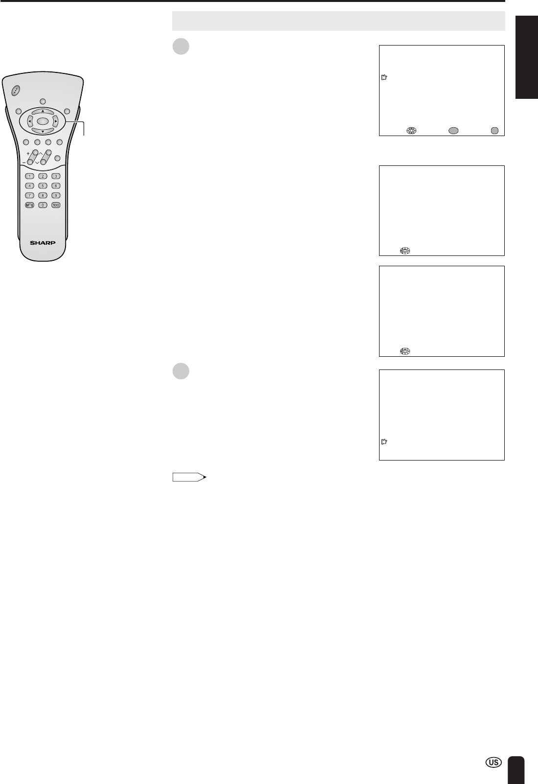
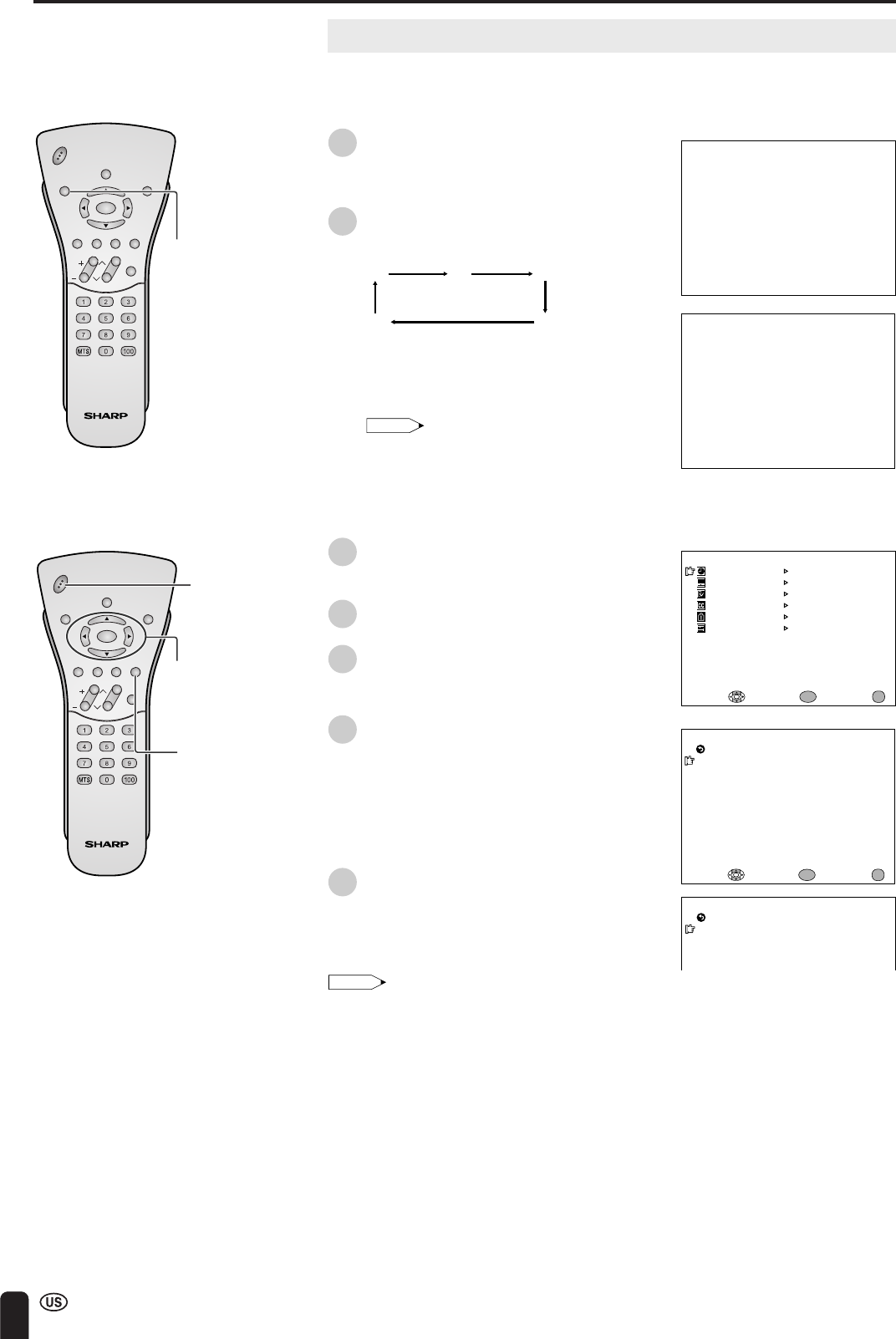
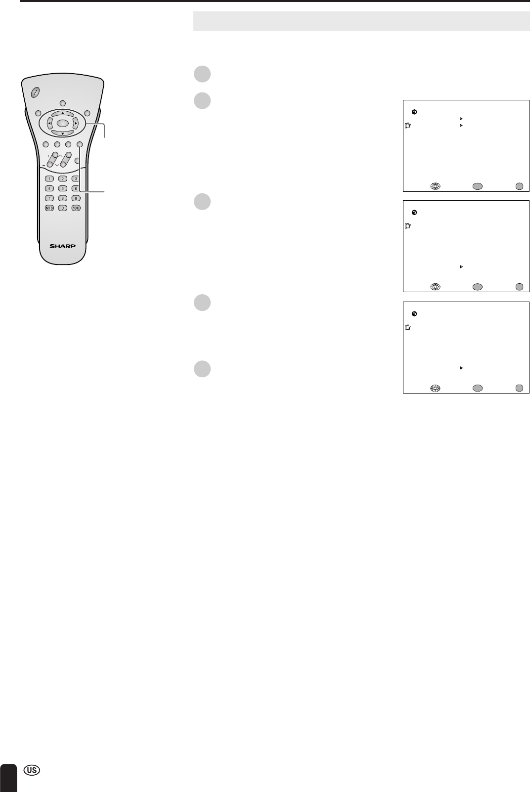
Changing channels by using Channel Select on the remote control
•This LCD TV set allows you to select up to 125 channels (1 to 125). To
select a channel, enter a 2- or 3-digit number.
To select a 1- or 2-digit channel
number (e.g., Channel 5):
Complete the following procedure within 4
seconds.
1
Press the button.
2
Press the
5
button.
Note:
•When selecting a 1-digit channel number,
do not fail to press the button first.
To select a 3-digit channel number
(e.g., Channel 115):
Complete the following procedure within 4
seconds.
1
Press the button.
2
Press the button.
3
Press the
5
button.
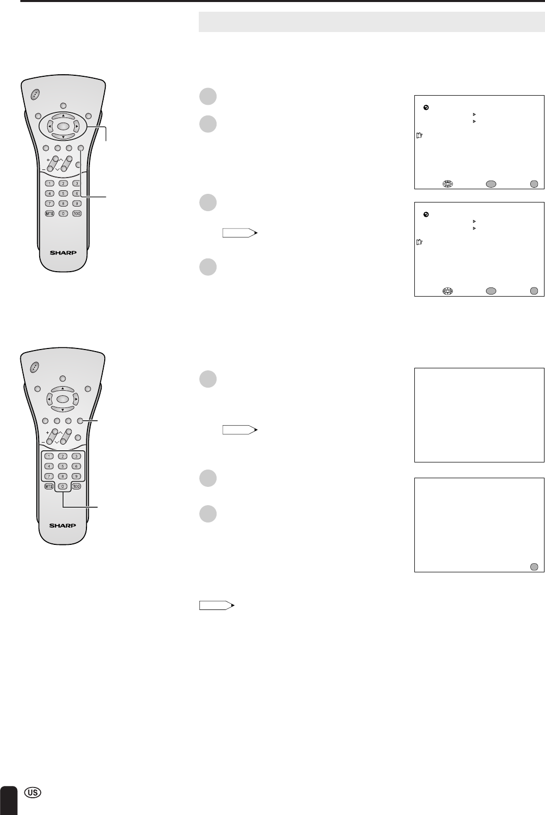
Note:
•The 3-digit channel number can be
selected only when the receiving mode is
set to “CABLE” in “CH-SETTING”. (For
details on setting the receiving mode, see
page 43.)
•Press FLASHBACK to show the previous
channel.
•Tuning operation may take a few seconds to
complete when using the remote control,
because of the wireless transmission speed.
This does not indicate a malfunction.
BASIC OPERATION (Continued)
Channel
Select
CH
(
)/()
FLASH-
BACK
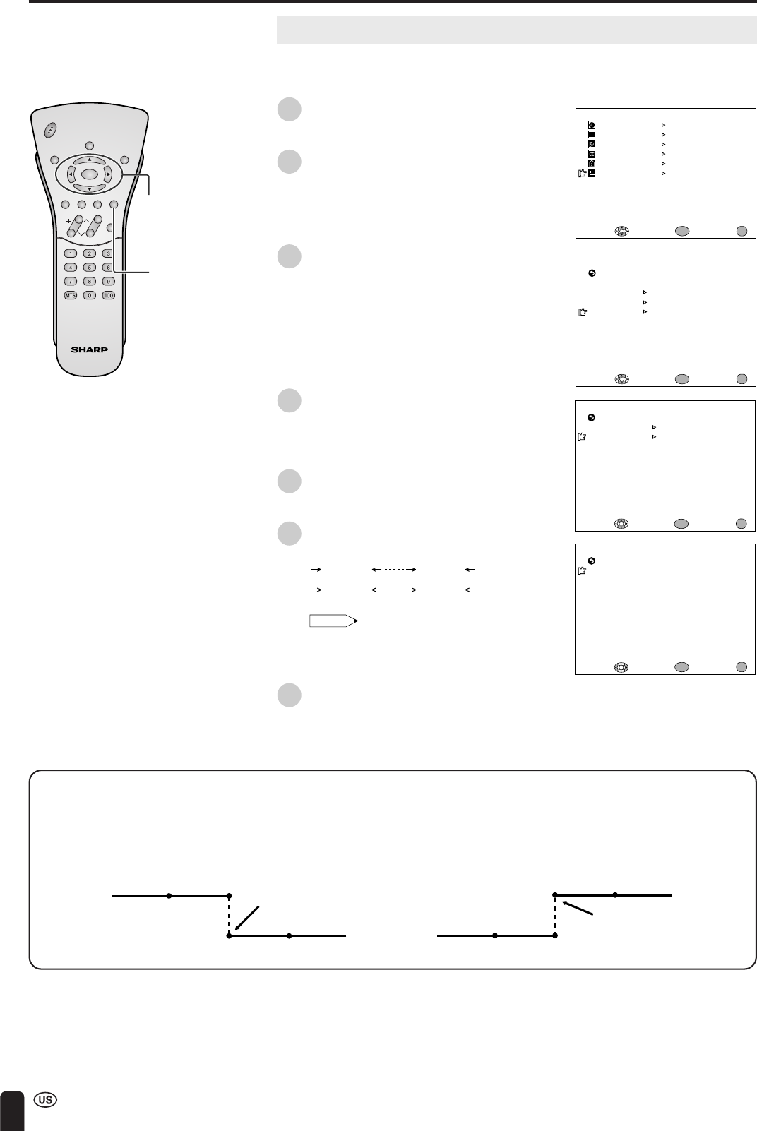
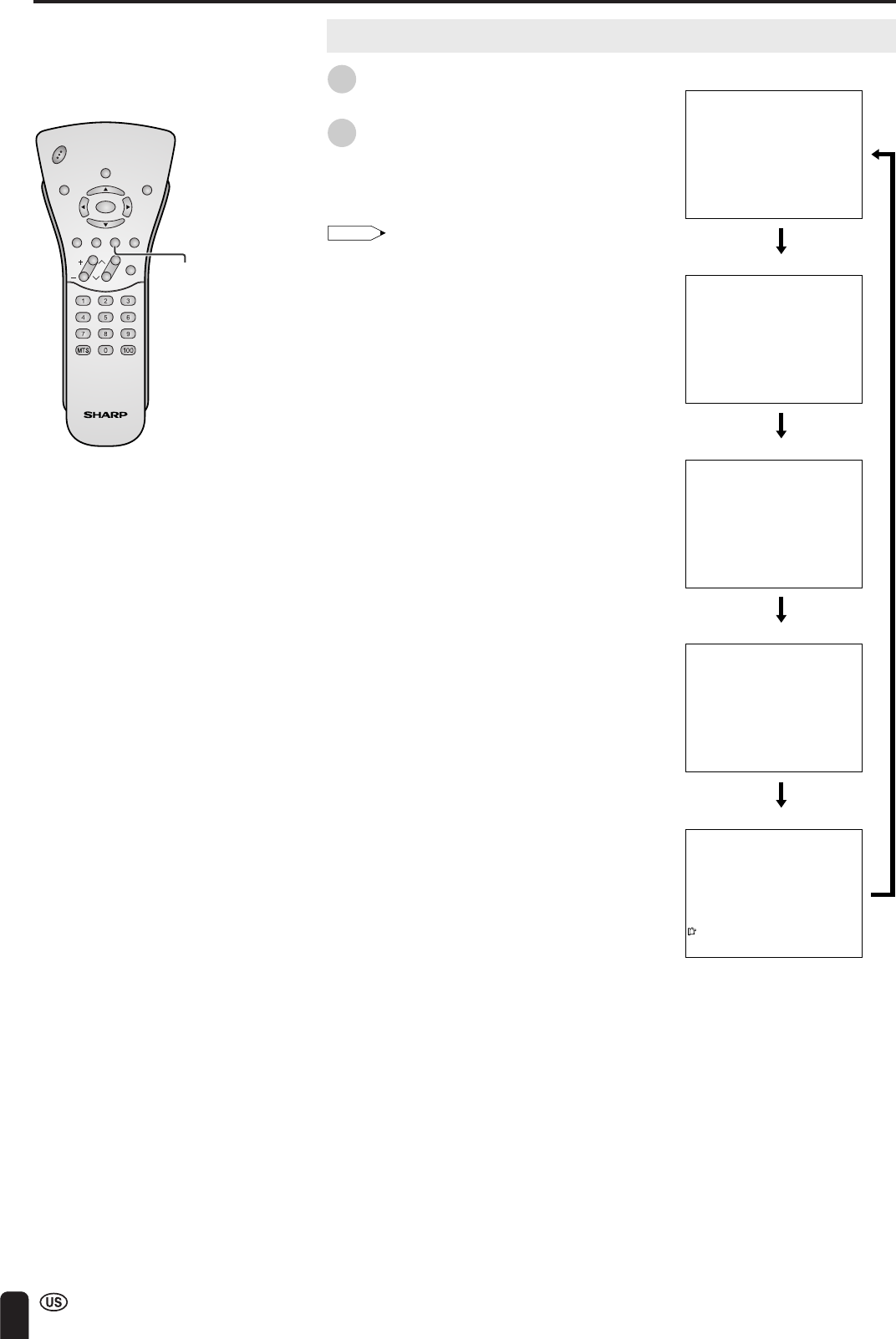
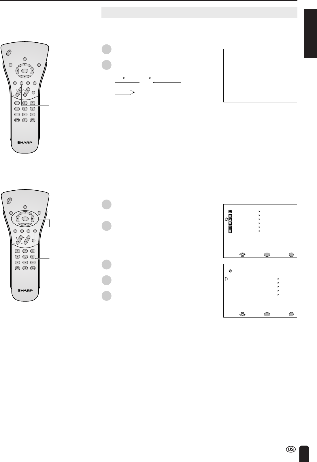
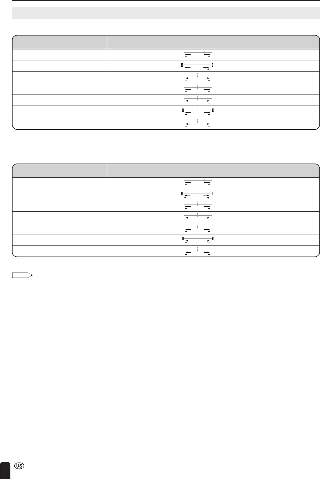
Changing channels with CH ()/() on the remote control
AirPress CH () and the channels change in the order shown below:
2→3→. . .→68→69 →2→3 →. . .
Press CH (
) and the channels change in the order shown below:
3→2→69→68 → . . .→3→2 → . . .
CablePress CH (
) and the channels change in the order shown below:
1→2→3→. . .→125→1→2→ 3→ . . .
Press CH
() and the channels change in the order shown below:
3 →2→1→125→ . . .→3→2→1→ . . .
CHVOL
POWER
ENTER
DISPLAY
MUTE
SLEEPPIC. FLIP
BRIGHT TV/VIDEOMENU
FLASH-
BACK
0–
5
1––
11–
115
ENGLISH
35
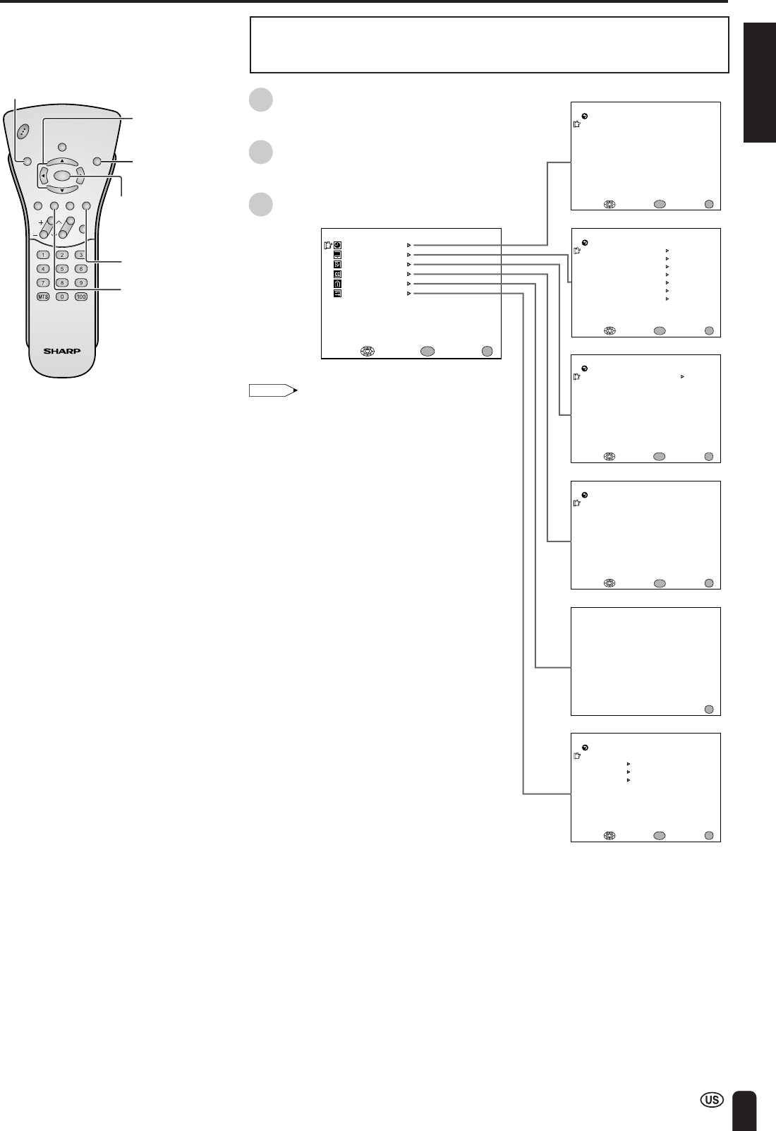
•This LCD TV set allows you to adjust the various settings using the menu
screen. Select the desired menu item by following the steps below and then
refer to the indicated page for details.
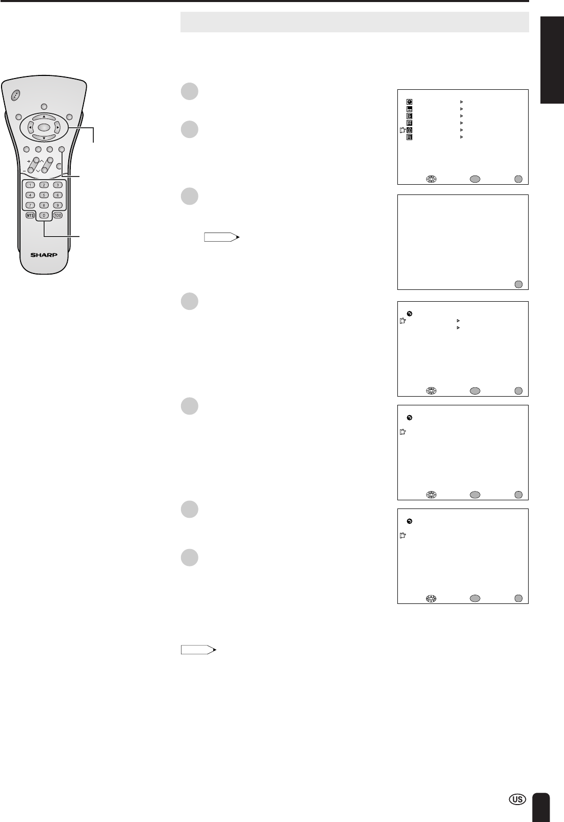
1
Press MENU to display the MENU
screen.
2
Press a/b to select the desired menu
item, and press ENTER.
3
Press MENU to exit.
SELECTING MENU ITEMS
Note:
•The displayed items differ depending on the
setting conditions.
•The selected item changes to yellow.
•Items in magenta cannot be selected.
•To return to the previous screen, select
“RETURN”.
•You can adjust some settings with the special
buttons: SLEEP, BRIGHT and PIC. FLIP (see
pages 36 to 38).
*The illustrations and on-screen displays in this
operation manual are for explanation purposes
and may vary slightly from the actual opera-
tions.
ENTER
BRIGHT
M
ENU
SLEEP TI
M
ER
VIDEO ADJUST
PRESET
CLOSED CAPTION
V–CHIP BLOCK
SET UP
SELECT:ENTER:EXIT:
ENTER
MENU
BRIGHTNESS[BRIGHT]
M
TS
AUTO PO
W
ER OFF
RETURN
[STEREO]
[OFF ]
PICTURE FLIP
AV2 IN/OUT
[NOR
M
AL]
[IN ]
PRESET
TRANSMISSION SETTING
PICTURE[ 50]
TINT
COLOR
BLACK LEVEL
SHARPNESS
SELECT:ENTER:EXIT:
VIDEO ADJUST(TV)
RETURN
[ 0]
[ 0]
[ 0]
[ 0]
RED-BLUE
[ 0]
GREEN
[ 0]
RESET
ENTER
MENU
SLEEP TI
M
ER
SELECT:ENTER:EXIT:
ENTER
RETURN
SLEEP TI
M
ER [––– RE
M
AIN]
ENTER
ENTER:
CC/TEXT
[OFF]
SELECT:EXIT:
RETURN
CLOSED CAPTION
INPUT SECRET NO.
––––
EXIT:
MENU
MENU
MENU
SELECT:ENTER:EXIT:
ENTER
MENU
BLUE SCREEN
[OFF]
LANGUAGE
SELECT:EXIT:
ENTER
RETURN
SET UP
CH–SETTING
ENTER:
MENU
CLOCK
BATTERY CHARGE
CHVOL
POWER
ENTER
DISPLAY
MUTE
SLEEPPIC. FLIP
BRIGHT TV/VIDEOMENU
FLASH-
BACK
MENU
PIC. FLIP
SLEEP
a/b
36
ADJUSTMENTS
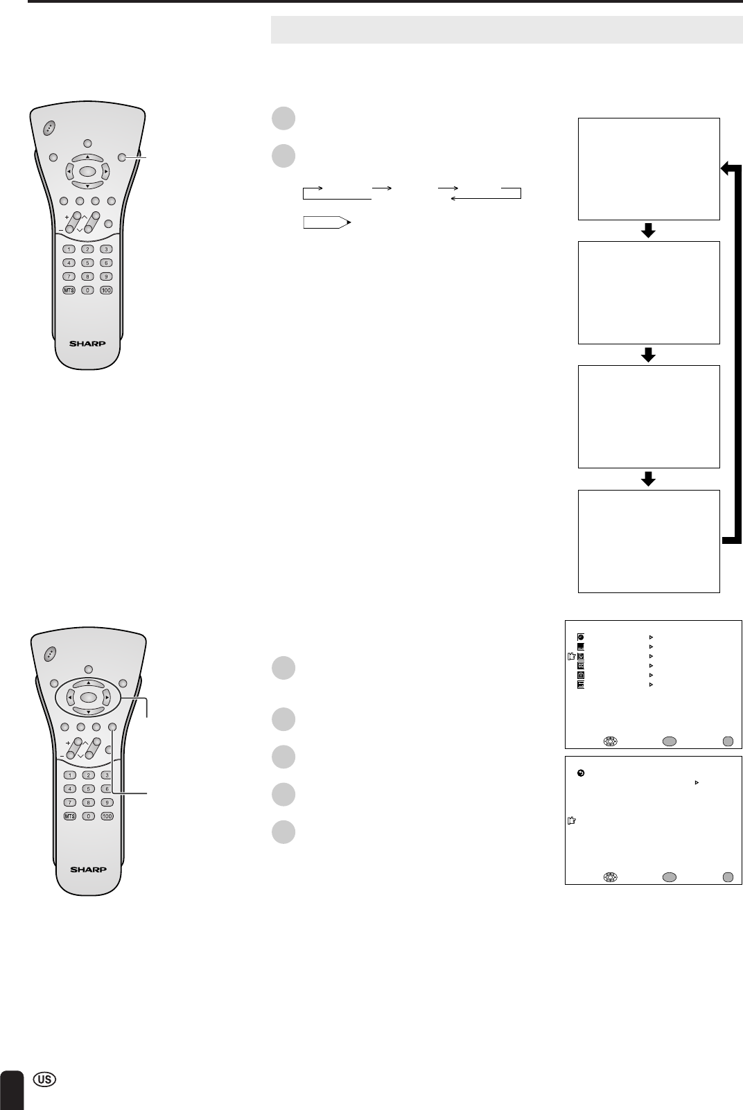
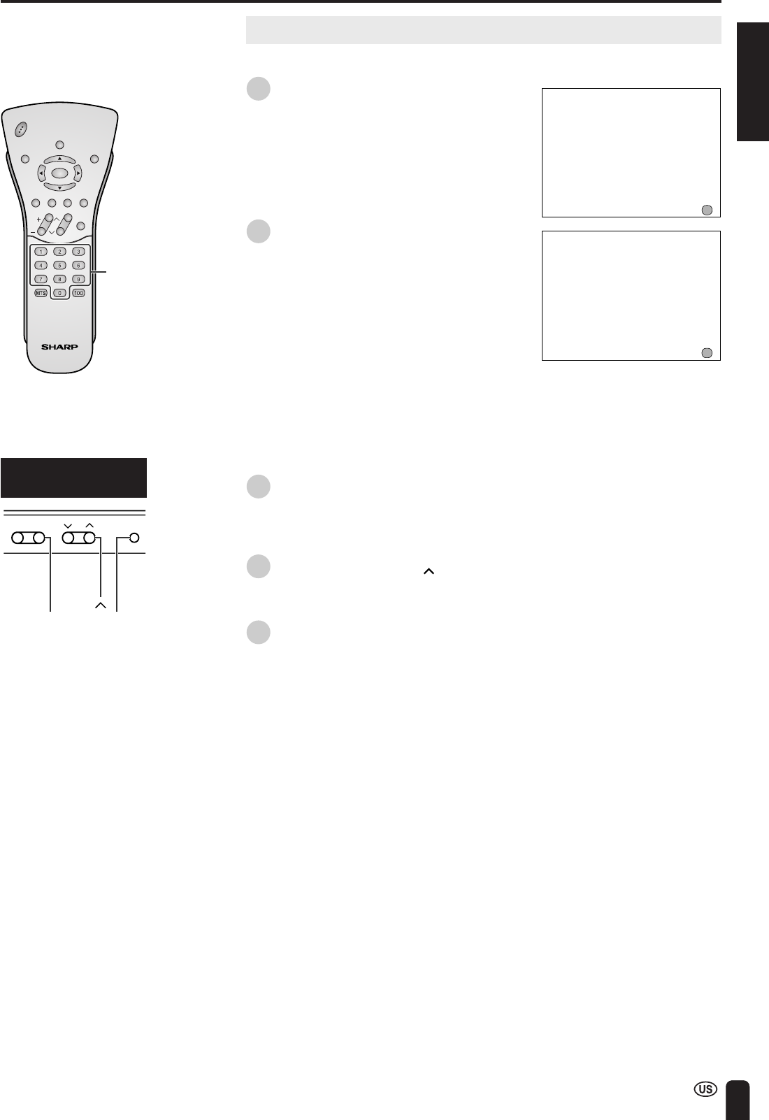
Adjusting SLEEP TIMER Settings
You can set the SLEEP TIMER to automatically turn off the TV.
Directly setting the SLEEP TIMER
1
Press SLEEP to display the SLEEP
TIMER screen.
2
Press SLEEP to set the sleep timer (in
minutes).
---
3060
90
(minutes)
120
•The SLEEP TIMER is turned off when
“---” is displayed.
Note:
•The SLEEP TIMER screen automatically
disappears in 3 seconds.
Setting the SLEEP TIMER on the
MENU screen
1
Press MENU to display the MENU
screen.
2
Press a/b to move the cursor to
“SLEEP TIMER”.
3
Press ENTER to display the SLEEP
TIMER screen, and press ENTER.
4
Press c/d to set the sleep timer (in
minutes), and press ENTER.
•The time can be set in increments of
30 minutes and in the range between
30 and 120 minutes.
•The SLEEP TIMER is turned off when
“---” is displayed.
5
Press MENU to return to the main
screen.
Note:
•When you set the SLEEP TIMER, the SLEEP
indicator LIGHTS UP RED.
•After you set the SLEEP TIMER, pressing MAIN
POWER on the TV set or POWER on the remote
control will cancel the SLEEP TIMER setting and
the SLEEP indicator goes out.
•5 minutes before the SLEEP TIMER turns off the
TV, “5 REMAIN” is displayed on the screen FOR
4 SECONDS. The SLEEP TIMER counts down
and shows a similar 4-second display for each
remaining minute until the timer turns off the TV.
––– REMAIN
60 REMAIN
SLEEP TI
M
ER
SELECT:EXIT:
RETURN
SLEEP TI
M
ER [––– RE
M
AIN]
ENTER:
ENTER
MENU
SLEEP TI
M
ER
RETURN
SLEEP TI
M
ER [–60 RE
M
AIN]
M
ENU
SLEEP TI
M
ER
VIDEO ADJUST
PRESET
CLOSED CAPTION
V–CHIP BLOCK
SET UP
SELECT:ENTER:EXIT:
ENTER
MENU
CHVOL
POWER
ENTER
DISPLAY
MUTE
SLEEPPIC. FLIP
BRIGHT TV/VIDEOMENU
FLASH-
BACK
SLEEP
CHVOL
POWER
ENTER
DISPLAY
MUTE
SLEEPPIC. FLIP
BRIGHT TV/VIDEOMENU
FLASH-
BACK
ENTER/
a/b/c/d
MENU
POWER
ENGLISH
37
ADJUSTMENTS (Continued)
BRIGHTNESS[BRIGHT]
M
ENU
SLEEP TI
M
ER
VIDEO ADJUST
PRESET
CLOSED CAPTION
V–CHIP BLOCK
SET UP
SELECT:ENTER:EXIT:
ENTER
MENU
BRIGHTNESS[BRIGHT]
M
TS
AUTO PO
W
ER OFF
RETURN
[STEREO]
[OFF ]
PICTURE FLIP
BATTERY CHARGE
AV2 IN/OUT
[NOR
M
AL]
[IN ]
PRESET
TRANSMISSION SETTING
SELECT:ENTER:EXIT:
ENTER
MENU
CHVOL
POWER
ENTER
DISPLAY
MUTE
SLEEPPIC. FLIP
BRIGHT TV/VIDEOMENU
FLASH-
BACK
ENTER/
a/b/c/d
CHVOL
POWER
ENTER
DISPLAY
MUTE
SLEEPPIC. FLIP
BRIGHT TV/VIDEOMENU
FLASH-
BACK
BRIGHT
MENU
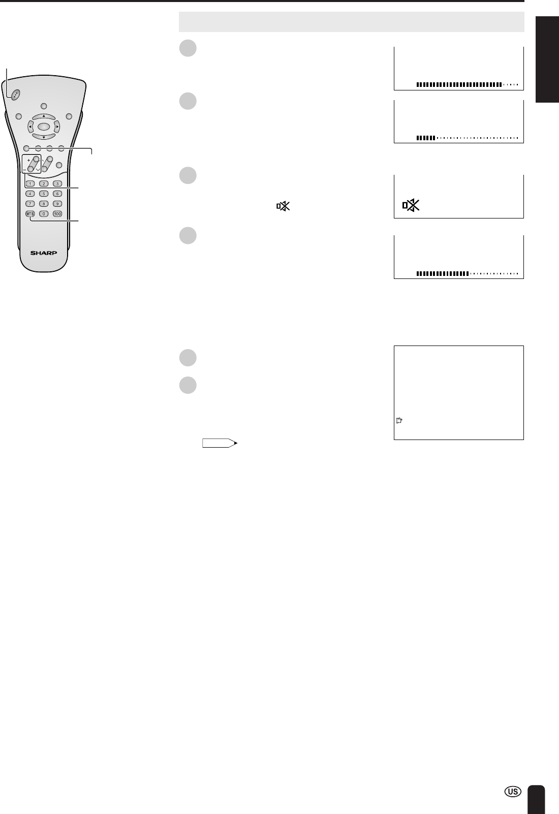
Adjusting BRIGHTNESS Settings
You can adjust the brightness of the screen.
Directly setting the BRIGHTNESS
1
Press BRIGHT to display the
BRIGHTNESS screen.
2
Press BRIGHT to change the setting.
BRIGHT
DARK
NORMAL
Note:
•The BRIGHTNESS screen automatically
disappears in 3 seconds.
•[BRIGHT]:maximum brightness
[NORMAL]:60% brightness (Suitable for
viewing in a well-lit area. Saves
energy.)
[DARK]:10% brightness (Sufficiently
bright when viewing in dim
areas.)
Setting the BRIGHTNESS on the MENU
screen
1
Press MENU to display the MENU
screen.
2
Press a/b to move the cursor to
“PRESET”, and press ENTER.
3
Press a/b to move the cursor to
“BRIGHTNESS”, and press ENTER.
4
Press c/d to change the setting, and
press ENTER.
5
Press MENU to return to the main
screen.
38
ADJUSTMENTS (Continued)
PI CTURE FL IP [NOR
M
AL]
PICTURE FLIP [MIRROR]
PICTURE FLIP [ROTATE]
PICTURE FLI P [UPSIDE DO
W
N]
ABC
ABC
ABC
ABC
M
ENU
SLEEP TI
M
ER
VIDEO ADJUST
PRESET
CLOSED CAPTION
V–CHIP BLOCK
SET UP
SELECT:ENTER:EXIT:
ENTER
MENU
CHVOL
POWER
ENTER
DISPLAY
MUTE
SLEEPPIC. FLIP
BRIGHT TV/VIDEOMENU
FLASH-
BACK
ENTER/
a/b/c/d
CHVOL
POWER
ENTER
DISPLAY
MUTE
SLEEPPIC. FLIP
BRIGHT TV/VIDEOMENU
FLASH-
BACK
PIC. FLIP
MENU
Adjusting PICTURE FLIP Settings
You can set the orientation of the picture.
Directly setting the PICTURE FLIP
1
Press PIC. FLIP to display the PICTURE
FLIP screen.
2
Press PIC. FLIP to change the setting.
MIRRORROTATENORMAL
UPSIDE DOWN
Note:
•The PICTURE FLIP screen automatically
disappears in 3 seconds.
•[NORMAL]:normal image
[MIRROR]:mirror image
[ROTATE]:rotated image
[UPSIDE DOWN]:upside down image
Setting the PICTURE FLIP on the
MENU screen
1
Press MENU to display the MENU
screen.
2
Press a/b to move the cursor to
“PRESET”, and press ENTER.
3
Press a/b to move the cursor to
“PICTURE FLIP”, and press ENTER.
4
Press c/d to change the setting, and
press ENTER.
5
Press MENU to return to the main
screen.
BRIGHTNESS[BRIGHT]
M
TS
AUTO PO
W
ER OFF
RETURN
[STEREO]
[OFF ]
PICTURE FLIP
BATTERY CHARGE
AV2 IN/OUT
[NOR
M
AL]
[IN ]
PRESET
TRANSMISSION SETTING
SELECT:ENTER:EXIT:
ENTER
MENU
ENGLISH
39
ADJUSTMENTS (Continued)
M
ENU
SLEEP TI
M
ER
VIDEO ADJUST
PRESET
CLOSED CAPTION
V–CHIP BLOCK
SET UP
SELECT:ENTER:EXIT:
ENTER
MENU
Selected itemFactory settingSetting options
TRANSMISSON SETTINGSee page 29.
BRIGHTNESS[BRIGHT]Maximum brightness[NORMAL]Brightness 60% → Suitable for viewing in a well-lit area.
Saves energy.
[DARK]Brightness 10%
→Sufficiently bright when viewing in dim areas.
MTS [STEREO] STEREO AUDIO[SAP]SECONDARY AUDIO PROGRAM
[MONO]Monophonic audio
AUTO POWER OFF[OFF][ON]The function automatically turns off power supply if a no-signal state
continues for a specified time (five minutes).
[OFF] The function is disabled.
PICTURE FLIP[NORMAL]Normal image[MIRROR] Mirror image →To display mirror images for special uses.
[ROTATE]Rotated image
→To display rotated images for special uses.
[UPSIDE DOWN] Upside down image
→ To display images upside down for
special uses.
AV2 IN/OUT[IN] AV-IN2 terminals selected[OUT ]Line Output is selected, Output volume is fixed, Speaker as input
terminals output is available.
BATTERY CHARGESee page 28.
*In AV1, AV2, AV3 or AV4 mode, MTS displayed in magenta cannot be selected.
ENTER/
a/b/c/d
MENU
CHVOL
POWER
ENTER
DISPLAY
MUTE
SLEEPPIC. FLIP
BRIGHT TV/VIDEOMENU
FLASH-
BACK
ABC
ABC
ABC
ABC
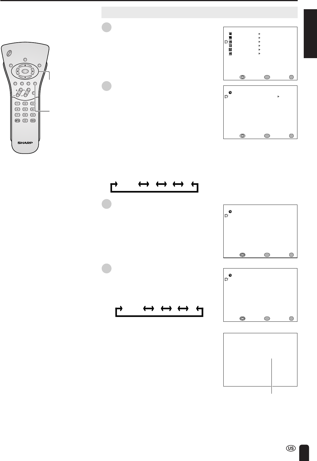
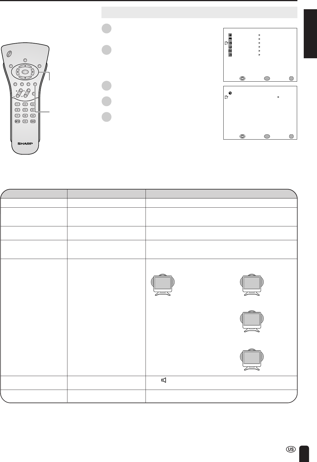
Adjusting PRESET Settings
1
Press MENU to display the MENU
screen.
2
Press a/b to move the cursor to
“PRESET”, and press ENTER.
3
Press a/b to move the cursor to the
desired item, and press ENTER.
4
Press c/d to change the setting, and
press ENTER.
5
Press MENU to return to the main
screen.
BRIGHTNESS[BRIGHT]
M
TS
AUTO PO
W
ER OFF
RETURN
[STEREO]
[OFF ]
PICTURE FLIP
BATTERY CHARGE
AV2 IN/OUT
[NOR
M
AL]
[IN ]
PRESET
TRANSMISSION SETTING
SELECT:ENTER:EXIT:
ENTER
MENU
40
ADJUSTMENTS (Continued)
LANGUAGE
ENGLISH
ESPAÑOL
FRANCAIS
SELECT:EXIT:
MENU
RETURN
ENTER:
ENTER
M
ENU
SLEEP TI
M
ER
VIDEO ADJUST
PRESET
CLOSED CAPTION
V–CHIP BLOCK
SET UP
SELECT:ENTER:EXIT:
ENTER
MENU
M
ENU
SLEEP TI
M
ER
VIDEO ADJUST
PRESET
CLOSED CAPTION
V–CHIP BLOCK
SET UP
SELECT:ENTER:EXIT:
ENTER
MENU
BLUE SCREEN
[OFF]
LANGUAGE
SELECT:EXIT:
ENTER
RETURN
SET UP
CH–SETTING
ENTER:
MENU
CLOCK
CHVOL
POWER
ENTER
DISPLAY
MUTE
SLEEPPIC. FLIP
BRIGHT TV/VIDEOMENU
FLASH-
BACK
ENTER
MENU
Adjusting LANGUAGE Settings
The language for the On-Screen Display can be ENGLISH, SPANISH or FRENCH.
1
Press MENU to display the MENU
screen.
2
Press a/b to move the cursor to
“SET UP”, and press ENTER.
3
Press a/b to move the cursor to
“LANGUAGE”, and press ENTER.
4
Press a/b to select the language, and
press ENTER.
a/b
ENGLISH
41
ADJUSTMENTS (Continued)
EXIT:
RETURN
PICTURE
50
–+
ADJUST :
SELECT:
MENU
PICTURE[ 50]
TINT
COLOR
BLACK LEVEL
SHARPNESS
SELECT:ENTER:EXIT:
VIDEO ADJUST(TV)
RETURN
[ 0]
[ 0]
[ 0]
[ 0]
RED-BLUE
[ 0]
GREEN
[ 0]
RESET
ENTER
MENU
M
ENU
SLEEP TI
M
ER
VIDEO ADJUST
PRESET
CLOSED CAPTION
V–CHIP BLOCK
SET UP
SELECT:ENTER:EXIT:
ENTER
MENU
M
ENU
SLEEP TI
M
ER
VIDEO ADJUST
PRESET
CLOSED CAPTION
V–CHIP BLOCK
SET UP
SELECT:ENTER:EXIT:
ENTER
MENU
CHVOL
POWER
ENTER
DISPLAY
MUTE
SLEEPPIC. FLIP
BRIGHT TV/VIDEOMENU
FLASH-
BACK
ENTER/
a/b/c/d
MENU
Adjusting VIDEO ADJUST Settings
Video adjustments have different selection items depending on TV mode or AV
mode (signal from an external device). (See page 42.)
1
Press MENU to display the MENU
screen.
2
Press a/b to move the cursor to
“VIDEO ADJUST”, and press ENTER.
3
Press a/b to move the cursor to the
desired item, and press ENTER.
4
Press c/d to change the setting.
Note:
•See page 42 for the settings.
5
Press MENU to return to the main
screen.
42
ADJUSTMENTS (Continued)
Adjusting VIDEO ADJUST Settings (Continued)
TV mode
Selected itemPress cPress d
PICTUREDecrease contrastIncrease contrast
TINTToward purpleToward green
COLORLower color intensityHigher color intensity
BLACK LEVELLess brightnessMore brightness
SHARPNESSSoft pictureSharp picture
RED-BLUEStronger redStronger blue
GREENWeaker greenStronger green
AV mode
Selected itemPress cPress d
PICTUREDecrease contrastIncrease contrast
TINTToward purpleToward green
COLORLower color intensityHigher color intensity
BLACK LEVELLess brightnessMore brightness
SHARPNESSSoft pictureSharp picture
RED-BLUEStronger redStronger blue
GREENWeaker greenStronger green
Note:
•When “BLUE SCREEN” is set to “ON”, VIDEO ADJUST settings displayed in magenta cannot be selected.
•Selecting “RESET” will return all settings to the factory settings. (See page 41.)
ENGLISH
43
ADJUSTMENTS (Continued)
SET UP
■EZ SETUP
When you move to an area with different broadcasting signals, the set will
automatically memorize the channel number and time. Refer to pages 22 and
23 for more information on EZ SETUP.
■SETTING THE AIR/CABLE
It is necessary to set the receiving mode to AIR or CABLE channels to receive
locally broadcast TV programs.
1
Switch the screen to TV mode and press
MENU to display the MENU screen.
2
Press a/b to move the cursor to
“SET UP”, and press ENTER.
3
Press a/b to move the cursor to
“CH-SETTING”, and press ENTER.
•When the screen is not in TV mode,
“CH-SETTING” is displayed in magenta
and not available.
4
Press c/d to move the cursor to
“AIR/CABLE”, and press ENTER.
5
Press c/d to move the cursor to the
desired mode, and press ENTER.
6
Press MENU to return to the main
screen.
•Receivable channels of your TV set are:
AIR channels:CABLE channels:
VHF: 2 through 131 (HRC and IRC)
UHF: 14 through 692 through 125 (STD, HRC and IRC)
CHVOL
POWER
ENTER
DISPLAY
MUTE
SLEEPPIC. FLIP
BRIGHT TV/VIDEOMENU
FLASH-
BACK
ENTER/
a/b/c/d
MENU
CH–SETTING
AIR/CABLE
EZ SETUP
CH SEARCH
CH
M
E
M
ORY
SELECT:ENTER:EXIT:
RETURN
ENTER
MENU
AIR/CABLE
SELECT:
EXIT:
AIR
CABLE
MENU
ENTER:
RETURN
ENTER
M
ENU
SLEEP TI
M
ER
VIDEO ADJUST
PRESET
CLOSED CAPTION
V–CHIP BLOCK
SET UP
SELECT:ENTER:EXIT:
ENTER
MENU
BLUE SCREEN
[OFF]
LANGUAGE
SELECT:EXIT:
ENTER
RETURN
SET UP
CH–SETTING
ENTER:
MENU
CLOCK
44
ADJUSTMENTS (Continued)
CHVOL
POWER
ENTER
DISPLAY
MUTE
SLEEPPIC. FLIP
BRIGHT TV/VIDEOMENU
FLASH-
BACK
ENTER/
a/b/c/d
MENU
CH–SETTING
AIR/CABLE
CH SEARCH
CH
M
E
M
ORY
RETURN
EZ SETUP
START:EXIT:
CH SEARCH
AIR2
MENU
M
ENU
SLEEP TI
M
ER
VIDEO ADJUST
PRESET
CLOSED CAPTION
V–CHIP BLOCK
SET UP
BLUE SCREEN
[OFF]
LANGUAGE
RETURN
SET UP
CH–SETTING
CLOCK
Press
d
to add channel 2
to the TV memory
Press
c
to erase channel 2
from the TV memory
CH–SETTING
AIR/CABLE
CH SEARCH
CH
M
E
M
ORY
RETURN
EZ SETUP
TO ADD:EXIT:
CH MEMORY
AIR2
MENU
TO ERASE:EXIT:
CH MEMORY
AIR2
MENU
CHVOL
POWER
ENTER
DISPLAY
MUTE
SLEEPPIC. FLIP
BRIGHT TV/VIDEOMENU
FLASH-
BACK
ENTER/
a/b/c/d
Channel
Select
MENU
SET UP (Continued)
■Saving broadcast TV channels in the memory
1
Press MENU to display the MENU
screen, press a/b to move the cursor
to “SET UP”, and press ENTER.
2
Press a/b to move the cursor to
“CH-SETTING”, and press ENTER.
3
Press a/b to move the cursor to
“CH SEARCH”, and press ENTER.
4
Press d. The tuner will search through
all available channels in your area and
add them to the TV memory.
•To interrupt CH SEARCH, press c. CH
SEARCH will stop at the current channel
and will not add any higher channels.
5
Press MENU to exit.
■Adding weak or additional channels or erasing unwanted channels from
TV memory
1
Press MENU to display the MENU
screen, press a/b to move the cursor
to “SET UP”, and press ENTER.
2
Press a/b to move the cursor to
“CH-SETTING”, and press ENTER.
3
Press a/b to move the cursor to
“CH MEMORY”, and press ENTER.
4
Use a/b or Channel Select to select
each desired channel to add or erase.
5
Press d to add the channel to the TV
memory or press c to erase the
channel from the TV memory.
6
Press MENU to exit.
•If CH SEARCH is performed again, the
previously memorized channels will be lost.
ENGLISH
45
ADJUSTMENTS (Continued)
CHVOL
POWER
ENTER
DISPLAY
MUTE
SLEEPPIC. FLIP
BRIGHT TV/VIDEOMENU
FLASH-
BACK
ENTER/
a/b/c/d
MENU
M
ENU
SLEEP TI
M
ER
VIDEO ADJUST
PRESET
CLOSED CAPTION
V–CHIP BLOCK
SET UP
SELECT:ENTER:EXIT:
ENTER
MENU
BLUE SCREEN
[OFF]
LANGUAGE
SELECT:EXIT:
ENTER
RETURN
SET UP
CH–SETTING
ENTER:
MENU
CLOCK
BLUE SCREEN
[ O N ]
LANGUAGE
SELECT:EXIT:
ENTER
RETURN
SET UP
CH–SETTING
ENTER:
MENU
CLOCK
Adjusting BLUE SCREEN Settings
■BLUE SCREEN
This function automatically turns the screen blue if no broadcast signal is
received.
1
Press MENU to display the MENU
screen.
2
Press a/b to move the cursor to
“SET UP”, and press ENTER.
3
Press a/b to move the cursor to
“BLUE SCREEN”, and press ENTER.
4
Press c/d to select “ON” or “OFF”, and
press ENTER.
5
Press MENU to return to the main
screen.
Note:
•When received signals are weak or interfered with by some other signals, the BLUE
SCREEN function may be activated. To watch the TV under such conditions, set
“BLUE SCREEN” to “OFF”.
•The BLUE SCREEN function is activated when AV1, AV2, AV3 or AV4 input mode is
selected with no signal being input.
46
ADJUSTMENTS (Continued)
CC/TEXT
[OFF]
SELECT:EXIT:
RETURN
CLOSED CAPTION
ENTER:
ENTER
MENU
CC/TEXT
[CC1]
EXIT:
RETURN
CLOSED CAPTION
ENTER:
ENTER
ADJUST :
MENU
M
ENU
SLEEP TI
M
ER
VIDEO ADJUST
PRESET
CLOSED CAPTION
V–CHIP BLOCK
SET UP
SELECT:ENTER:EXIT:
ENTER
MENU
CHVOL
POWER
ENTER
DISPLAY
MUTE
SLEEPPIC. FLIP
BRIGHT TV/VIDEOMENU
FLASH-
BACK
ENTER/
a/b/c/d
MUTE
MENU
Adjusting CLOSED CAPTION Settings
■SETTING CLOSED CAPTION
•This TV set is equipped with an internal Closed
Caption decoder. “Closed Caption” is a system
which allows conversations, narration, and sound
effects in TV programs and home videos to be
viewed as captions on the TV screen (see the
illustration).
•Not all programs and videos will offer closed
captioning. Please look for the “
” symbol to
ensure that captions will be shown.
•The Closed Caption broadcasts can be viewed in two modes: CAPTION and
TEXT. For each mode, two channels are available: CH1 and CH2.
The CAPTION mode shows subscripts of dialogs and commentaries of TV
dramas and news programs while allowing a clear view of the picture.
The TEXT mode displays various information over the picture (such as TV
program schedules and weather forecasts, etc.) that is independent of the TV
programs.
Setting the CLOSED CAPTION on the
MENU screen
1
Press MENU to display the MENU
screen.
2
Press a/b to move the cursor to
“CLOSED CAPTION” , and press
ENTER.
3
Press ENTER for the CLOSED
CAPTION setting.
4
Press c/d to change the CLOSED
CAPTION setting, and press ENTER.
CC1CC2OFFT1T2
Note:
•CC1:CAPTION mode for CH1 data
CC2:CAPTION mode for CH2 data
T1:TEXT mode for CH1 data
T2:TEXT mode for CH2 data
5
Press MENU to return to the main
screen.
Note:
•Color characters for closed captioning are not
supported with this TV. Characters are white only.
•If a broadcast contains Closed Caption data and
MUTE is pressed, the TV set enters CAPTION
mode automatically. Pressing MUTE again will
return the TV set to its previous condition.
•Closed Caption may malfunction (white blocks,
strange characters, etc.) if signal conditions are
poor or if there are problems at the broadcast
source. This does not necessarily indicate a
problem with your TV set.
•If any button is pressed to call up the On-Screen
Display while viewing a Closed Caption broad-
cast, the closed captions will disappear momen-
tarily.
•If no TEXT broadcast is being received while
viewing in the TEXT mode, the screen may
become dark and blank for some programs.
Should this occur, switch the CLOSED CAPTION
mode to “OFF”.
ENGLISH
47
ADJUSTMENTS (Continued)
Adjusting V-CHIP Settings
■V-CHIP
•This function allows TV programs to be restricted and TV usage to be
controlled based on FCC data. It prevents children from watching violent or
sexual scenes that may be harmful.
•Restriction of TV programs includes two ratings that contain information about
the program: the MPAA rating and the TV Parental Guidelines. The MPAA
rating is restricted by age. TV Parental Guidelines are restricted by age and
content.
•Since a TV program may use either the MPAA rating or the TV Guidelines,
both should be adjusted for complete control.
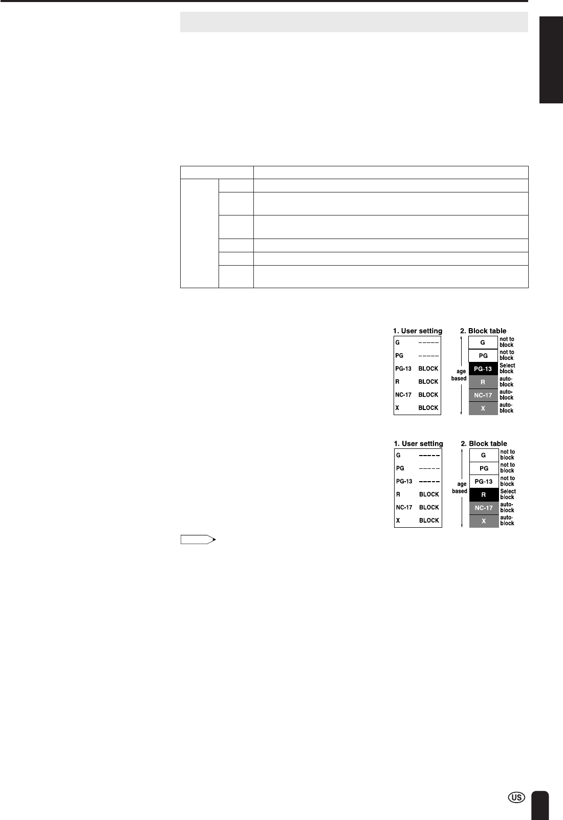
[1] MPAA RATING
RATINGDescription
GGENERAL AUDIENCES. All ages admitted.
PGPARENTAL GUIDANCE SUGGESTED. Some material may not be suitable
for children.
PG-13PARENTS STRONGLY CAUTIONED. Some material may be
inappropriate for children under 13.
RRESTRICTED. Under 17 requires accompanying parent or adult guardian.
NC-17NO ONE 17 AND UNDER ADMITTED.
XX is an older rating that is unified with NC-17 but may be encoded in the
data of older movies.:
MPAA RATING
Example 1:
When PG-13 in the age-based rating is
blocked, this will also automatically block
the higher ratings R, NC-17 and X.
Example 2:
When R in the age-based rating is
blocked, this will also automatically block
the higher ratings NC-17 and X.
Note:
•The MPAA rating is only age-based.
⇑
age
based
⇓
48
ADJUSTMENTS (Continued)
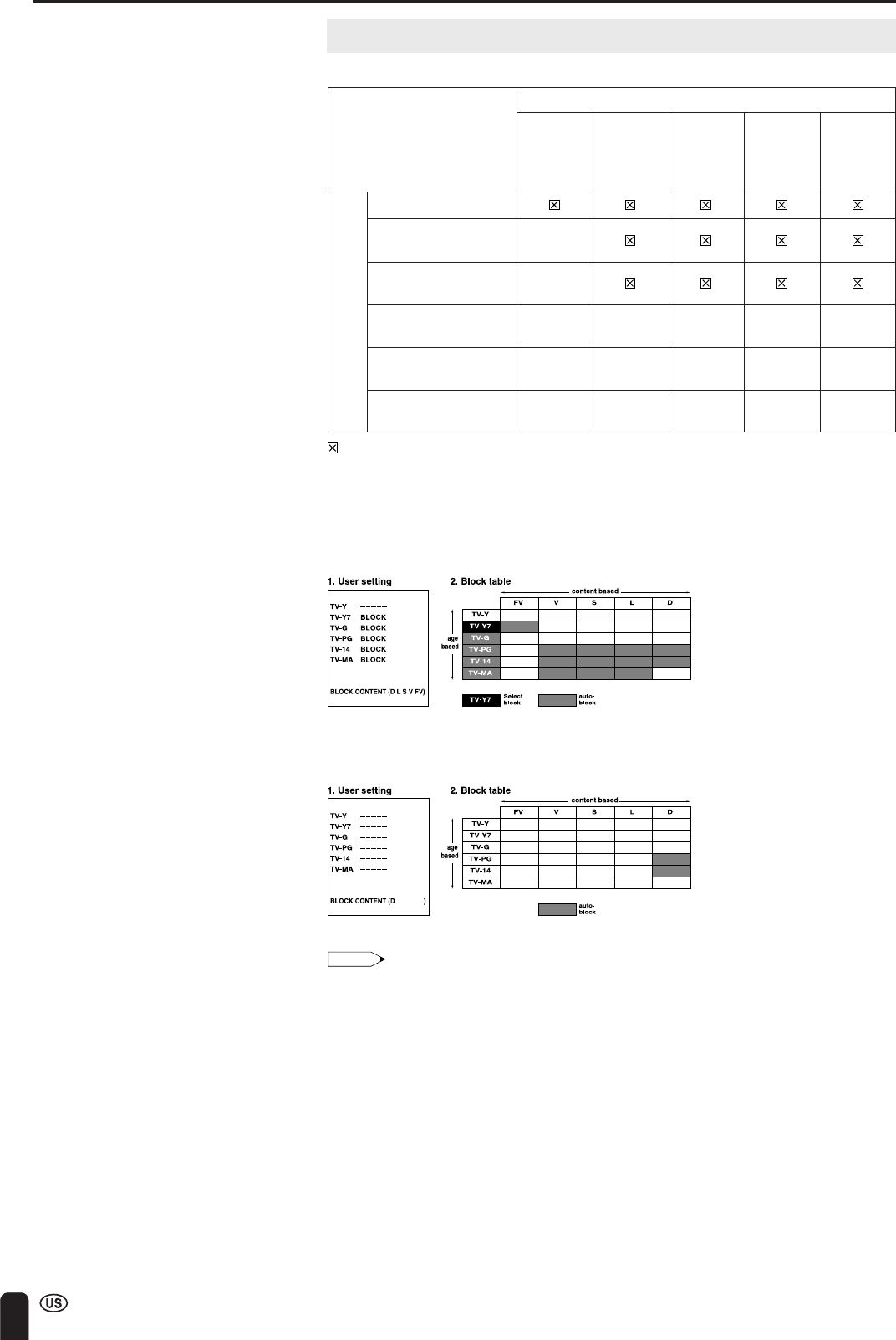
⇐
content based
⇒
FVVSLD
(Fantasy (Violence)(Sexual(Adult(Sexually
Violence)Situation)Language)Suggestive
Dialog)
TV-Y (All children)
TV-Y7 (Direct to Older
✕
Children)
TV-G (GeneralX
Audience)
TV-PG (Parental
✕✕✕✕
Guidance Suggested)xxx
TV-14 (Parents
✕✕✕✕
Strongly Cautioned)X
TV-MA (MatureX
✕✕✕
Audience Only)
RATING
⇑
age
based
⇓
Adjusting V-CHIP Settings (Continued)
[2] TV PARENTAL GUIDELINES
:The content rating can be set, but this rating is not normally broadcast by TV stations.
✕:The content rating can be set.
TV PARENTAL GUIDELINES
Example 1:
When TV-Y7 in the age-based rating is set to “BLOCK”, this will automatically block the higher
ratings: TV-G, TV-PG, TV-14 and TV-MA. In addition, D, L, S, V and FV in CONTENT are
automatically blocked unless you manually set “BLOCK CONTENT”.
Example 2:
When no item in the age-based rating is blocked, D in the content-based rating will be automatically
blocked.
Note:
•Age-based ratings can be modified by the content-based ratings, but only in the combina-
tions indicated by an X in the table above.
•Choosing a lower age-based rating blocks the higher age-based ratings regardless of
content rating settings.
•If you set “TV-Y” and “TV-Y7” to “BLOCK”, “CONTENT” will display all items.
ENGLISH
49
ADJUSTMENTS (Continued)
INPUT SECRET NO.
––––
EXIT:
MENU
M
PAA
TV GUIDELINES
STATUS
SELECT:EXIT:
RETURN
V–CHIP BLOCK
[OFF]
ENTER:
ENTER
MENU
M
PAA
G [–––––]
EXIT:
RETURN
PG [BLOCK]
PG–13 [BLOCK]
R [BLOCK]
NC–17 [BLOCK]
X [BLOCK]
ENTER:
ENTER
ADJUST :
MENU
M
PAA
G [–––––]
EXIT:
RETURN
PG [–––––]
PG–13 [–––––]
R [–––––]
NC–17 [–––––]
X [–––––]
ENTER:
ENTER
SELECT:
MENU
ENTER/
a/b/c/d
Channel
Select
CHVOL
POWER
ENTER
DISPLAY
MUTE
SLEEPPIC. FLIP
BRIGHT TV/VIDEOMENU
FLASH-
BACK
MENU
M
ENU
SLEEP TI
M
ER
VIDEO ADJUST
PRESET
CLOSED CAPTION
V–CHIP BLOCK
SET UP
SELECT:ENTER:EXIT:
ENTER
MENU
Adjusting V-CHIP Settings (Continued)
■SETTING V-CHIP
[1] MPAA RATING
1
Press MENU to display the MENU
screen.
2
Press a/b to move the cursor to
“V-CHIP BLOCK”, and press ENTER.
3
“INPUT SECRET NO.” will be displayed.
Input the 4-digit secret number by using
Channel Select, and press ENTER.
Note:
•When you input the secret number for the
first time, press ENTER to register.
Otherwise, continue to step 4.
4
Press a/b to move the cursor to
“MPAA”, and press ENTER.
5
Press a/b to move the cursor to “PG”,
and press ENTER.
6
Press c/d to select BLOCK, and press
ENTER. If you set “PG” to “BLOCK”,
“PG-13”, “R”, “NC-17” and “X” are
automatically blocked.
7
Press MENU to return to the main
screen.
Note:
•If you set “G” to “BLOCK”, all ratings are automatically blocked.
•If you set “X” to “BLOCK”, “G”, “PG”, “PG-13”, “R” and “NC-17” are not blocked.
50
ADJUSTMENTS (Continued)
CHVOL
POWER
ENTER
DISPLAY
MUTE
SLEEPPIC. FLIP
BRIGHT TV/VIDEOMENU
FLASH-
BACK
ENTER/
a/b/c/d
MENU
M
PAA
TV GUIDELINES
STATUS
SELECT:EXIT:
RETURN
V–CHIP BLOCK
[OFF]
ENTER:
ENTER
MENU
TV GUIDELINES
TV–Y [ –––––]
EXIT:
BLOCK CONTENT
[D L S V FV]
RETURN
TV–Y7 [BLOCK]
TV–G [BLOCK]
TV–PG [BLOCK]
TV–14 [BLOCK]
TV–
M
A [BLOCK]
ENTER:
ENTER
ADJUST :
MENU
TV GUIDELINES
TV–Y [ –––––]
SELECT:EXIT:
BLOCK CONTENT
[ ]
RETURN
TV–Y7 [–––––]
TV–G [–––––]
TV–PG [–––––]
TV–14 [–––––]
TV–
M
A [–––––]
ENTER:
ENTER
MENU
Adjusting V-CHIP Settings (Continued)
[2] TV GUIDELINES
● Setting TV GUIDELINES
1
Repeat steps 1 to 3 of [1] MPAA
RATING. (See page 49.)
2
Press a/b to move the cursor to
“TV GUIDELINES”, and press ENTER.
3
Press a/b to move the cursor to
“TV-Y7”, and press ENTER.
4
Press c/d to select “BLOCK”, and
press ENTER. If you set “TV-Y7” to
“BLOCK”, “TV-G”, “TV-PG”, “TV-14” and
“TV-MA” are automatically blocked. In
addition, “D”, “L”, “S”, “V” and “FV” in
“CONTENT” are automatically blocked.
5
Press MENU to return to the main
screen.
ENGLISH
51
ADJUSTMENTS (Continued)
CHVOL
POWER
ENTER
DISPLAY
MUTE
SLEEPPIC. FLIP
BRIGHT TV/VIDEOMENU
FLASH-
BACK
ENTER/
a/b/c/d
MENU
TV GUIDELINES
TV–Y [ –––––]
SELECT:EXIT:
BLOCK CONTENT
[ ]
RETURN
TV–Y7 [–––––]
TV–G [–––––]
TV–PG [–––––]
TV–14 [–––––]
TV–
M
A [–––––]
ENTER:
ENTER
MENU
D [–––––]
EXIT:
RETURN
L [BLOCK]
S [–––––]
V [–––––]
FV [–––––]
BLOCK CONTENT
ENTER:
ENTER
ADJUST :
MENU
M
PAA
TV GUIDELINES
STATUS
SELECT:EXIT:
RETURN
V–CHIP BLOCK
[OFF]
ENTER:
ENTER
MENU
D [–––––]
SELECT:EXIT:
RETURN
L [–––––]
S [–––––]
V [–––––]
FV [–––––]
BLOCK CONTENT
ENTER:
ENTER
MENU
Adjusting V-CHIP Settings (Continued)
■Setting BLOCK CONTENT
1
Repeat steps 1 to 3 of [1] MPAA
RATING. (See page 49.)
2
Press a/b to move the cursor to
“TV GUIDELINES”, and press ENTER.
3
Press a/b to move the cursor to
“BLOCK CONTENT”, and press ENTER.
4
Press a/b to move the cursor to the
desired item, and press ENTER.
5
Press c/d to select “BLOCK” or “-----”
(unblock), and press ENTER.
6
Press MENU to return to the main
screen.
Note:
•If you set “TV-14” to “BLOCK”, “TV-MA” is automatically blocked. Contents “D”, “L”, “S” and
“V” are automatically blocked by X in the table on page 48.
52
ADJUSTMENTS (Continued)
CHVOL
POWER
ENTER
DISPLAY
MUTE
SLEEPPIC. FLIP
BRIGHT TV/VIDEOMENU
FLASH-
BACK
ENTER/
a/b/c/d
MENU
M
PAA
TV GUIDELINES
STATUS
ENTER:EXIT:
RETURN
V–CHIP BLOCK
[ON ]
ENTER:
ENTER
MENU
ADJUST :
M
PAA
TV GUIDELINES
STATUS
SELECT:EXIT:
RETURN
V–CHIP BLOCK
[OFF]
ENTER:
ENTER
MENU
V–CHIP HAS BEEN ACTIVATED
TV–Y
INPUT SECRET NO.
––––
EXIT:
MENU
CHVOL
POWER
ENTER
DISPLAY
MUTE
SLEEPPIC. FLIP
BRIGHT TV/VIDEOMENU
FLASH-
BACK
MENU
Channel
Select
Adjusting V-CHIP Settings (Continued)
[3] ACTIVATING V-CHIP BLOCK
● Setting STATUS
You can activate V-CHIP BLOCK after setting [1] MPAA RATING and/or [2]
TV GUIDELINES.
1
Repeat steps 1 to 3 of [1] MPAA
RATING. (See page 49.)
2
Press a/b to move the cursor to
“STATUS”, and press ENTER.
3
Press c/d to set “STATUS” to “ON”,
and press ENTER.
Note:
•If “STATUS” is set to “OFF”, “V-CHIP
BLOCK” will not be activated.
4
Press MENU to return to the main
screen.
[4] CANCELING THE V-CHIP BLOCK SCREEN WHILE V-CHIP BLOCK IS
ACTIVATED
1
“V-CHIP HAS BEEN ACTIVATED”
appears if you watch a program with the
same Program Rating data you
configured.
Note:
•“V-CHIP HAS BEEN ACTIVATED” will not
be displayed if “STATUS” is not configured
to “ON”.
2
Press MENU to display “INPUT
SECRET NO.”
3
Input the 4-digit secret number by using
Channel Select; V-CHIP BLOCK is
temporarily canceled. If you input an
incorrect secret number, “SECRET NO.
IS INCORRECT” is displayed. In this
case, input the correct secret number.
Note:
•If you turn the power on from off, V-CHIP BLOCK will be activated again.
•If you select “V-CHIP BLOCK” again by using MENU, V-CHIP BLOCK will be turned on
again.
ENGLISH
53
ADJUSTMENTS (Continued)
CHVOL
POWER
ENTER
DISPLAY
MUTE
SLEEPPIC. FLIP
BRIGHT TV/VIDEOMENU
FLASH-
BACK
INPUT SECRET NO.
––––
EXIT:
MENU
INPUT SECRET NO.
* * * *
EXIT:
MENU
Channel
Select
CHVOLMENU
-
+
VOL (+)
CH ( )
MENU
Adjusting V-CHIP Settings (Continued)
[5] CHANGING V-CHIP BLOCK SETTINGS
1
Repeat steps 1 to 2 of [1] MPAA
RATING, then “INPUT SECRET NO.”
will be displayed.
2
Input the 4-digit secret number by using
Channel Select; the V-CHIP select
mode will be displayed. Set V-CHIP
BLOCK again.
[6] CHANGING OR CLEARING THE SECRET NUMBER
If you forget the secret number, clear the secret number as follows.
1
Repeat steps 1 to 2 of [1] MPAA
RATING, or 1 to 2 of [4] CANCELING
THE V-CHIP BLOCK SCREEN WHILE
V-CHIP BLOCK IS ACTIVATED, then
“INPUT SECRET NO.” will be displayed.
2
Press and hold both CH () and VOL
(+) on the TV set simultaneously until
the message “INPUT SECRET NO.”
BLINKS.
3
Press MENU to exit.
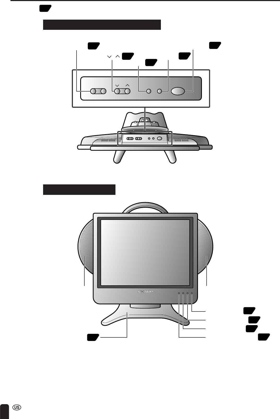
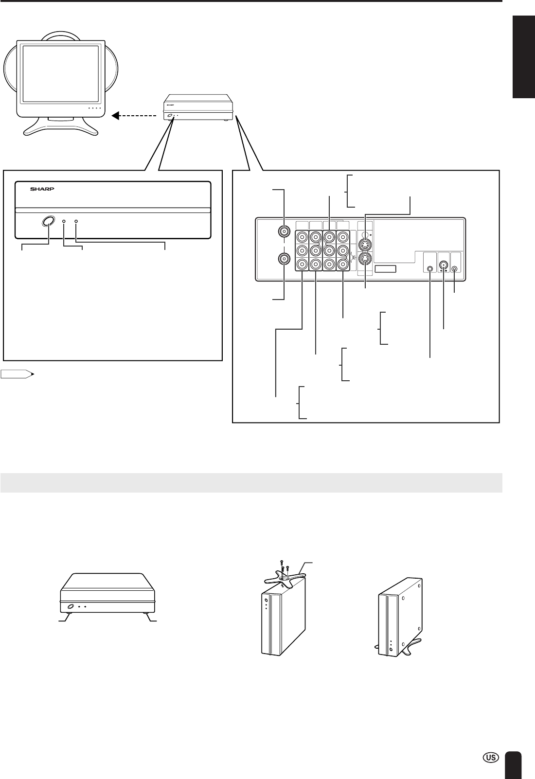
Upper control panel
of the main unit
54
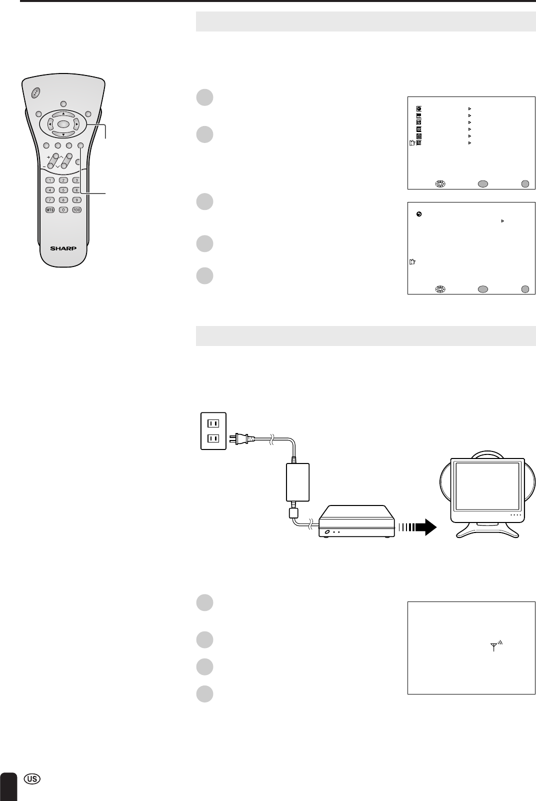
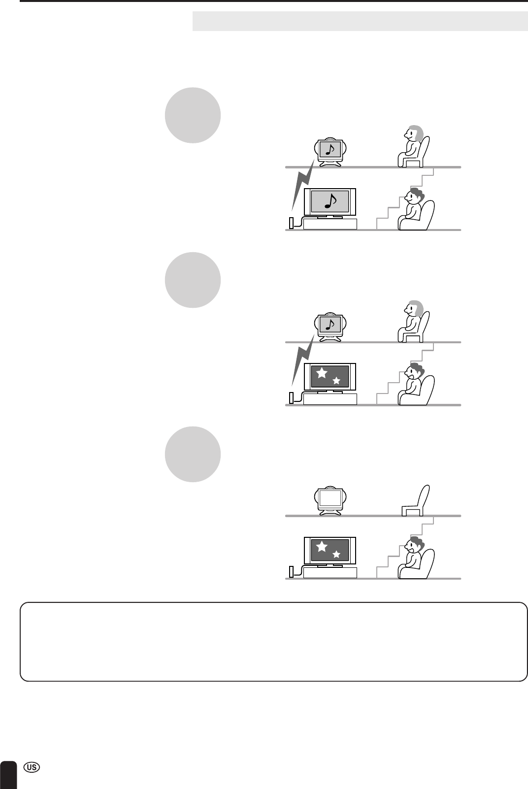
CONNECTION SYSTEM WITH VARIOUS WAYS OF BEING USED
Examples of Various Uses
The Wireless Center outputs pictures and sound via transmission to a television
receiver of this unit. Various manners of use are possible as it is possible to
connect your own main TV and the Wireless Center using a cable.
How the Wireless Center is used
It is possible for the same pictures and programs to be watched separately at
different locations.
It is also possible for separate pictures and programs to be enjoyed by one person
using a television on a second floor while another person is watching on a main TV
in a living room.
Even if the power supply of the Wireless Center is turned off, pictures and sound
can be received by the main TV connected to the output terminals (through) and
enjoyment is therefore possible even with a single television.
•An antenna through output, and a video 1 (through) output are provided at the LC-15L1U Wireless Center.
It is therefore possible for the system to be on without detriment to the advantages of using the main TV currently
being viewed. (Output also takes place when the power supply of the Wireless Center is turned off).
•Only three items of this equipment can be used in the same environment. If more are used, then it may not be
possible to watch television due to mutual interference.
ENGLISH
55
CONNECTION SYSTEM WITH VARIOUS WAYS OF BEING USED (Continued)
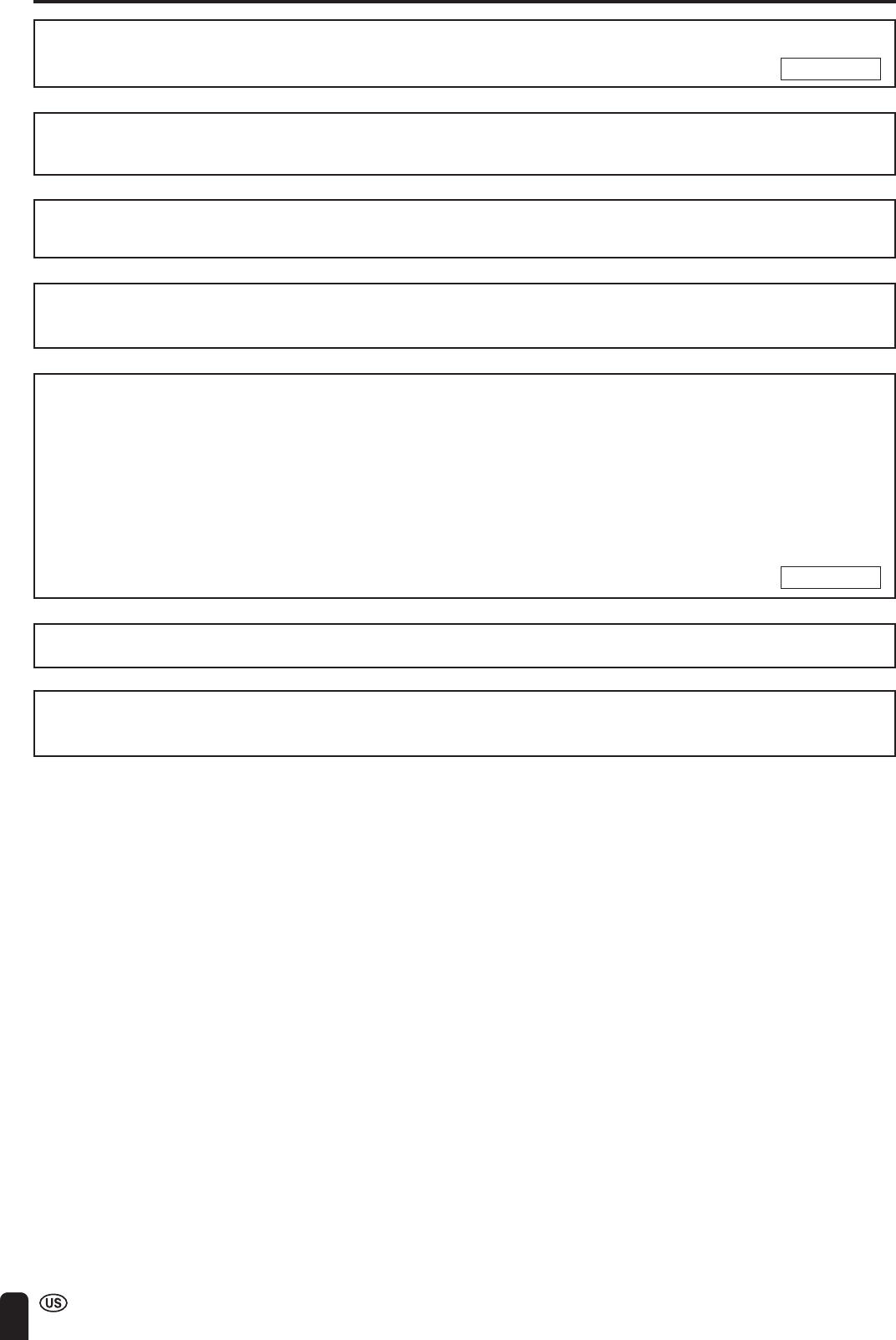
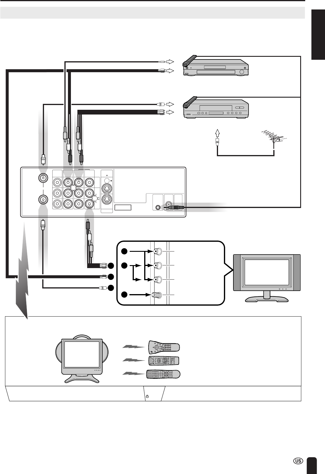
Connecting System Chart of LC-15L1U
See pages 56 to 61 for the connection.
Video input terminal
Audio (L) input terminal
Audio (R) input terminal
Antenna input terminal
Main TV
(Large-size TV in a living room)
Antenna cable
Audio cord
Audio/Video cord
Video cord
To Video output
terminal
To Audio output
terminal
DVD player
VCR
Video controller
Video controller
Video controller
IN
OUT
AV-IN1AV-IN1AV-IN3
IR
OUT
POWER
INPUT
DC12V
FACTORY
SERVICE
S-VIDEO
MONITOR
OUT
MONITOR
OUT
VIDEO
AUDIO
L
AUDIO
R
AV-IN2
/OUT
ANT.
Audio/Video cord
Wireless Center
(Rear view)
To Audio/Video
output terminal
VHF/UHF antenna
To antenna
input terminal
Antenna cable
Antenna cable
To antenna
output terminal
1
1
2
3
2
3
Main unit
(LC-15L1U)
Operation in a separate room
Equipped with
AV-IN4 system
(for playing games)
An equipment can be operated by transmitting remote control signals from
the equipment connected with the Wireless Center to the main unit.
Remote control for LC-15L1U
Remote control for DVD player
Remote control for VCR
TransmissionTransmission
56
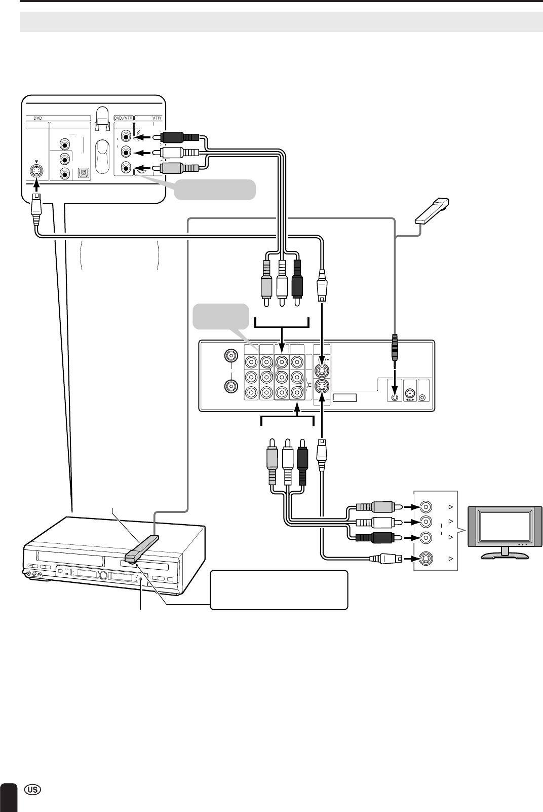
CONNECTION SYSTEM WITH VARIOUS WAYS OF BEING USED (Continued)
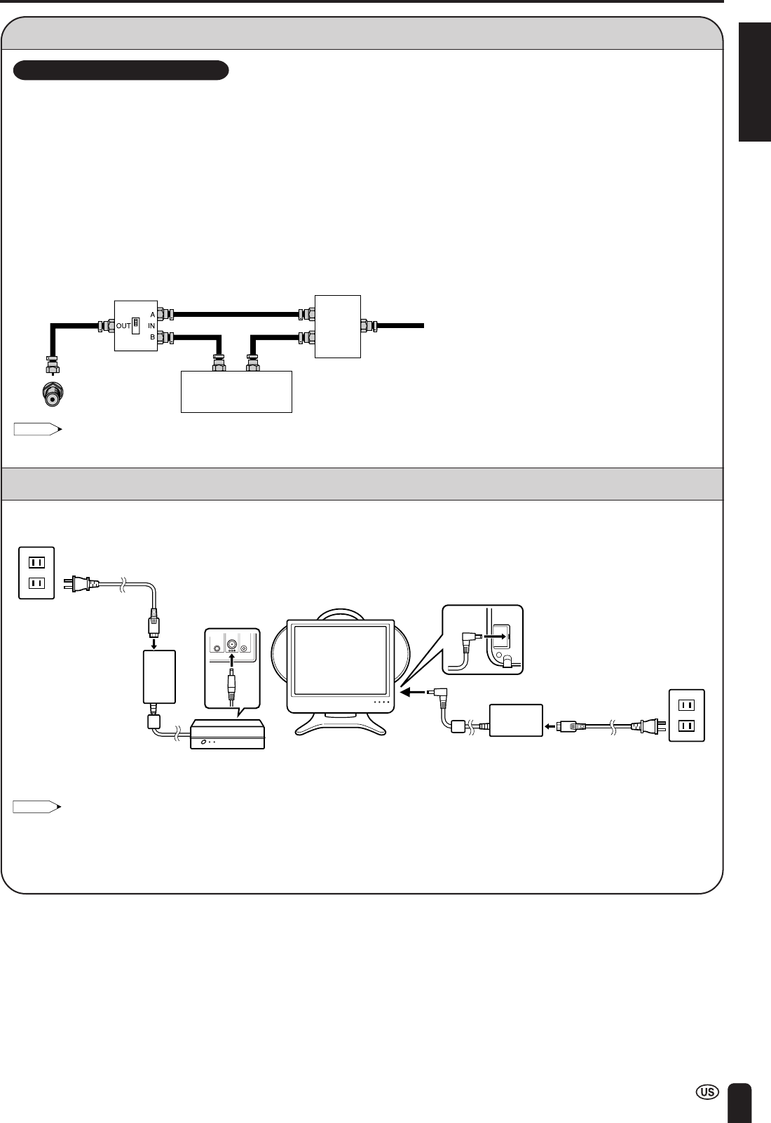
Method of Connecting External Equipment
■Place where Wireless Center is installed
Wireless Center should be placed on or beside video equipment. However, make sure that the Wireless Center is as far as
possible away from the antenna input terminal of a television or video equipment.
Note:
Regarding S-VIDEO terminal
•When VIDEO input/output and S-VIDEO input/output are connected at the AV3/AV4 input/output of this unit at the same time, S-VIDEO input/
output has priority over the other.
IN
OUT
AV-IN1AV-IN1AV-IN3
IR
OUT
POWER
INPUT
DC12V
FACTORY
SERVICE
S-VIDEO
MONITOR
OUT
MONITOR
OUT
VIDEO
AUDIO
L
AUDIO
R
AV-IN2
/OUT
ANT.
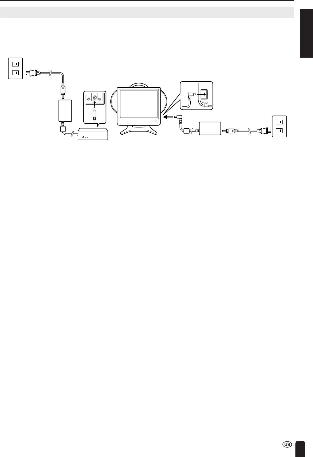
AC wall
outlet
AC adapter
AC cord
AC wall outlet
AC cord
AN
T
S-VIDEO
AUDIO
DIGITAL
OPTICAL
CO-
AXIAL
OUTIN
TV
R
L
AUDIO
VIDEO
R
L
AUDIO
VIDEO
R
L
DVD player
Decoder
To Audio/Video
output terminal
To AV-IN1
(S-VIDEO) terminal
To AV-IN2/OUT (AV)
terminal
To AV-IN3 (AV)
terminal
To S-VIDEO output terminal
To Audio/Video
output terminal
Rear
Front
VCR, etc.
Installation
example
To input/output terminal
(
Red
)
(
White
)
(
Yellow
)
(
Red
)
(
White
)
(
Yellow
)
(
Red
)
(
White
)
(
Yellow
)
(
Red
)
(
White
)
(
Yellow
)
Wireless Center
When connecting to
equipment with
an S-video terminal.
S-video cord
(commercially available)
Audio/Video cord
(commercially available)
Connect to the terminal
of the same color.
Connect to the terminal
of the same color.
ENGLISH
57
CONNECTION SYSTEM WITH VARIOUS WAYS OF BEING USED (Continued)
IN
OUT
AV-IN1AV-IN1AV-IN3
IR
OUT
POWER
INPUT
DC12V
FACTORY
SERVICE
S-VIDEO
MONITOR
OUT
MONITOR
OUT
VIDEO
AUDIO
L
AUDIO
R
AV-IN2
/OUT
ANT.
DVD player
Decoder
To Video control terminal
Front
VCR etc.
Installation
example
(The video controller should be
fixed with the accessory tape once
the place where it is to be installed
has been decided.)
/
PLAY
STOP
OPEN/
CLOSE
OPERATE
VCR/DVD
SELECTOR
VCR MENU
DVD SETUP
TAPE
SPEED
ON
SCREEN
TIMER
ON/OFF
TITLE
DVD MENU
DISPLAY
EJECT
FUNCTION
CONTROL
PROG/
REPEAT
CLEAR
RETURN
REVFWD
SET
ENTER
ZERO BACK
VCR DVDAM/PM
INPUT SELECT
PAUSE/STILL
REC
VCR/DVD COMBINATION
SLOW
CH
VCRDVD
SKIP
DPSS
AUDIO
OUTPUT
ZOOM
KARAOKE
SELECT
SKIP SEARCH
Wireless Center
The video controller is fixed so that
the transmitter of the video controller
faces the infrared receiver of the remote
control for the video equipment.
Video controller (supplied)
Infrared receiver of the remote
control (an example)
The remote control
for the external
equipment is used
for operating a
VCR or a DVD.
Method of Using the Video Controller
A maximum of two items of video equipment can be operated using the video controller.
■Cautions regarding installation of video controller
•The position of the infrared receiver of the remote control varies depending on the manufacturer or the type of the video
cassette recorder. Generally, it is a small round-shaped part close to the liquid crystal display portion.
•Make sure that the transmitter of the video controller is facing the infrared receiver of the remote control.
•When installing the video controller, try first to transmit remote control signals from the equipment connected with the
Wireless Center to the main unit to find a position where the connected equipment can be operated.
Note:
Regarding video controller
•Connect VIDEO terminal and AUDIO output terminals of equipment to play an image to VIDEO terminal and AUDIO input terminals on the
Wireless Center respectively. After that, connect the video controller to the video control terminal of Wireless Center.
•When installing video controller, make sure that this transmitter is facing the infrared receiver of the remote control for the connected
equipment. It is possible to operate a connected equipment by facing the remote control for the equipment connected to the Wireless
Center toward the infrared receiver of the remote control for the main unit (TV unit) and pressing the button.
58
CONNECTION SYSTEM WITH VARIOUS WAYS OF BEING USED (Continued)
TV main unit
/
PLAY
STOP
OPEN/
CLOSE
OPERATE
VCR/ DVD
SELECTOR
VCR MENU
DVD SETUP
TAPE
SPEED
ON
SCREEN
TIMER
ON/OFF
TITLE
DVD MENU
DISPLAY
EJECT
FUNCTION
CONTROL
PROG/
REPEAT
CLEAR
RETURN
REVFWD
SET
ENTER
ZERO BACK
VCR DVDAM/PM
INPUT SELECT
PAUSE/STILL
REC
VCR/DVD COMBINATION
SLOW
CH
VCRDVD
SKIP
DPSS
AUDIO
OUTPUT
ZOOM
KARAOKE
SELECT
SKIP SEARCH
CHVOL
POWER
ENTER
DISPLAY
MUTE
SLEEPPIC. FLIP
BRIGHT TV/VIDEOMENU
FLASH-
BACK
AV1
The remote control
for the main unit is
used for switching
over the input of
the main unit.
The remote control
for the external
equipment is used
for operating a
VCR or a DVD.
CHVOL
POWER
ENTER
DISPLAY
MUTE
SLEEPPIC. FLIP
BRIGHT TV/VIDEOMENU
FLASH-
BACK
TV/VIDEO
Example
Watching Played back Image from External Equipment
When watching played back images from external equipment, operations are
carried out such as switching over the input source using the remote control for the
TV main unit, and playing back and selecting channels using the remote control for
the external equipment.
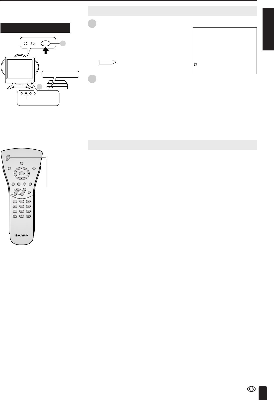
1
Turn on the power supply for Wireless
Center.
2
Turn on the power supply for the
external equipment.
Power ON
•Regarding operating method, refer to
the operation manual for the
equipment.
3
Press TV/VIDEO to select the video
input source being connected to.
4
Make operations such as playing back
or selecting channels using the remote
control for the external equipment.
ENGLISH
59
CONNECTION SYSTEM WITH VARIOUS WAYS OF BEING USED (Continued)
VIDEOS-VIDEO
AUDIO
RL
How to Fix Cable Clamps
AUDIO
AV-IN4
VIDEO
S-VIDEO
L
R
HEAD
PHONE
(Red)
(Yellow)
(White)
(Red)
(White)
(Yellow)
Game system, VCR, DVD, etc.
Audio/Video cord
(commercially
available)
S-Video cord (commercially available)
Cable clamps
AC wall outlet
1Insert cable clamps into the hole for
the table stand.
2Cables are fitted in the cover of the table
stand and then fitted into the cable
clamps.
Note:
•Game devices must always be connected to the input terminal of the main unit. If a game device is connected to the Wireless Center, you
cannot enjoy the game comfortably because of a delay in the transmission of pictures and sound.
•When connecting to both the VIDEO input and S-VIDEO input terminals for AV-IN4, priority is given to the S-VIDEO input terminal.
•When signals from external devices connected to the Wireless Center do not appear to be transmitted to the main unit properly, connect
the external devices to the AV-IN4 terminal of the main unit.
Connecting a Home Video Game System, etc. (AV-IN4)
60
CONNECTION SYSTEM WITH VARIOUS WAYS OF BEING USED (Continued)
IN
OUT
AV-IN1AV-IN1AV-IN3
IR
OUT
POWER
INPUT
DC12V
FACTORY
SERVICE
S-VIDEO
MONITOR
OUT
MONITOR
OUT
VIDEO
AUDIO
L
AUDIO
R
AV-IN2
/OUT
ANT.
Wireless Center
TV
VIDEO
L
R
S-VIDEO
AUDIO
AN
T
S-VIDEO
AUDIO
DIGITAL
OPTICAL
CO-
AXIAL
OUTIN
TV
R
L
AUDIO
VIDEO
R
L
AUDIO
VIDEO
R
L
To Video control terminal
To AV-IN1 (S-VIDEO) terminal
To MONITOR OUT
(S-VIDEO) terminal
To S-VIDEO output terminal
To Audio/Video
output terminal
Rear
Front
VCR etc.
Installation
example
(The video controller should be
fixed with the accessory tape
once the place where it is to be
installed has been decided.)
(
Red
)
(
White
)
(
Yellow
)
(
Red
)
(
White
)
(
Yellow
)
(
Red
)
(
White
)
(
Yellow
)
(
Red
)
(
White
)
(
Yellow
)
The video controller is fixed so that
the transmitter of the video controller
faces the infrared receiver of the remote
control for the video equipment.
Infrared receiver (an example)
Video controller (supplied)
When connecting to
equipment having
an S-video terminal.
S-video cord
(commercially available)
S-video cord
(commercially
available)
Audio/Video cord
(commercially available)
Audio/Video cord
(commercially available)
Connect to the terminal
of the same color.
To AV-IN1 (AV)
terminal
To MONITOR OUT
(AV) terminal
Connect to the
terminal of the
same color.
How to Use Video 1 Output
Since a video signal received at the video input terminal is output as is from the video output terminal, it is possible to enjoy
pictures and sounds from an external device (such as a VCR) connected to the video 1 input on another television while
watching television on the main unit.
ENGLISH
61
CONNECTION SYSTEM WITH VARIOUS WAYS OF BEING USED (Continued)
IN
OUT
AV-IN1AV-IN1AV-IN3
IR
OUT
POWER
INPUT
DC12V
FACTORY
SERVICE
S-VIDEO
MONITOR
OUT
MONITOR
OUT
VIDEO
AUDIO
L
AUDIO
R
AV-IN2
/OUT
ANT.
Wireless Center
When connecting to amplifier
or stereo, etc.
To Videoinput terminal
(
Red
)
(
White
)
(
Yellow
)
(
Red
)
(
White
)
(
Yellow
)
Audio/Video cord
(commercially available)
To AV-IN2/OUT terminal
To audio input terminal
Monitor Output for Picture and Sound Output from AV-IN2/OUT Terminal
It is possible to output picture and sound being received by this unit from the AV-IN2/OUT terminal of the Wireless Center.
Note:
•Pictures and sound you have recorded cannot be used without permission from the copyright owner, other than for personal enjoyment.
•Transmission of pictures and sound from the Wireless Center to the main unit may take some time. For this reason, a picture that is slightly
delayed from the actual picture is displayed on the main unit. When recording pictures and sound on DVD or video while watching the main
unit, it will take about one second from pressing the picture record button on the remote control until actual picture recording starts.
•When recording pictures or watching pictures on another device via the AV-IN2/OUT terminal of the Wireless Center, “AV2-IN/OUT” is set
to “OUT ”.
If the television power supply is switched “off” using the remote control when the “AV2-IN/OUT” is set to “OUT ”, the power supply of the
Wireless Center is also put into a standby state, but output from the AV-IN2/OUT terminal continues as is. Therefore, if the main power
supply of the Wireless Center is switched off, output from the AV-IN2/OUT terminal stops.
*In the following cases, the power supply is in a standby state, but output from the AV-IN2/OUT terminal is possible.
•When television main power is “off”.
•When the power supply button of the remote control is “off”.
•Also in cases when communication is not possible due to some fault, output from the AV-IN2/OUT terminal is interrupted. For the purpose
of power conservation, when output from the AV-IN2/OUT terminal is not being used, it is recommended that the main power of the
Wireless Center be turned off.
*Even if the main power of the Wireless Center is turned off, the antenna output and video 1 are output.
62
•Make sure the antenna cable is properly connected.
•Bad reception could be the problem.
TROUBLESHOOTING
ProblemCheck item
Reference
pages
There is no
picture.
There is no
picture from
AV-IN1/2.
13
–
32
31
Sound
Picture
•Make sure the AC adapter is properly inserted in the power outlet.
•Reception other than those of broadcasting stations can be consid-
ered.
•Make sure the input mode is set to TV.
•Make sure the MAIN POWER buttons of the main unit and Wireless
Center are on.
There is no
picture or
sound.
Picture
•Make sure the BLACK LEVEL is properly adjusted.
•The fluorescent lamp may have reached the end of service life.
•Make sure the S-VIDEO terminal has nothing connected.
There is no
sound.
•Make sure the volume is not set to minimum.
•Make sure the sound is not set to mute.
•Make sure that headphones are not connected.
There is no
picture or
sound, just
noise.
•Make sure the antenna cable is properly connected.
•Bad reception could be the problem.
Picture is not
clear.
Picture is light
or improperly
tinted.
•Check color adjustment.
The picture is
too dark.
•Press the BRIGHT button or set the BRIGHTNESS settings.
•Check PICTURE and BLACK LEVEL adjustment.
•The fluorescent lamp may have reached the end of service life.
Remote control does not work.
•Check the batteries of the remote control.
•Make sure the remote sensor window is not under strong lighting.
41
65
56, 60
33
33
16
12
–
12
–
41, 42
37
41
65
11
11
•The broadcasted EDS signal may be weak. Check the antenna.
•Carry out EZ SETUP, SETTING THE CLOCK again.
•If EDS signal is not sent, set the clock using the MANUAL CLOCK
Setting.
–
22-26
26
The clock (AUTO CLOCK) cannot
be set.
•The radio waves used by the product are high frequency, so that
there are features such as direct advance travelling, reflection,
refraction, diffraction, interference etc., similar to that of light. The
strength of the waves therefore varies depending on the location,
which may cause the pictures and sound to become unclear,
become wavy, or stop.
•Is the distance between the Wireless Center and the television
product too far? Use within a range that the radio waves can reach.
•Are you at a location that is particularly susceptible to electrical
noise?
•Set “DISTANCE” to “FAR”.
•The product utilizes wireless transmissions, so that fast moving
images may become distorted, but this is not a malfunction.
9
–
9
30
–
Blocks of noise appear on the
pictures. Sound becomes inter-
rupted.
■Before calling for repair services, make the following checks for possible remedies to the encountered symp-
toms.
TV set
ENGLISH
63
ProblemCheck item
Reference
pages
9
•Are there any devices operating in the vicinity of the product such as
Bluetooth devices, or wireless LANs, or microwave ovens, etc. that
utilize the same frequency band (2.4 GHz) as the product?
•There are good and bad positions in terms of wave conditions with
regards to the influence of obstacles and reflectors. Try changing
the location of the television product slightly.
•Is the video controller connected?
•Is the transmitter of the video controller facing the infrared receiver
of the remote control for the VCR?
•Does the VCR work when operating the remote control by directly
facing the VCR? (If the VCR is still not working, it can be considered
that the battery of the remote control has run out.)
9
57
57
56
TROUBLESHOOTING (Continued)
Pictures are suddenly stopped and
sound is interrupted.
Pictures and sound cannot be
received.
The VCR will not operate even
though the remote control is
operated by facing toward the TV
main unit.
64
TROUBLESHOOTING (Continued)
ProblemCheck item
•The reception may be weak.
•The quality of the broadcast may also be bad.
•Make sure the antenna is facing the correct direction.
•Make sure the outside antenna has not been disconnected.
•Make sure the antenna is facing the correct direction.
•Broadcast waves may be reflected from adjacent mountains or buildings.
•There may be interference from automobiles, trains, high-voltage lines, neon
lights, etc.
•There may be interference between the antenna cable and power cable. Try
positioning them further apart.
•Is the unit receiving interference from other devices?
Transmission antennas of radio broadcasting stations and transmission antennas
of amateur radios and cellular phones may also cause interference.
•Use the unit as far apart as possible from devices that may cause possible
interference.
Antenna
The picture is not
sharp.
The picture
moves.
The picture is
doubled or
tripled.
The picture is
spotted.
There are stripes
on the screen or
colors fade.
■ Cautions regarding use in high and low temperature environments
•When the unit is used in a low temperature space (e.g. room, office), the picture may leave trails or appear slightly delayed. This is not
a malfunction, and the unit will recover when the temperature returns to normal.
•Do not leave the unit in a hot or cold location. Also, do not leave the unit in a location exposed to direct sunlight or near a heater, as
this may cause the cabinet to deform and the LCD panel to malfunction.
(Storage temperature: –4°F to +140°F (–20°C to +60°C))
■ It is not a malfunction in the following cases.
•There are cases where reception of pictures is not good because of the distance between the main unit and Wireless Center, or
obstacles. Install the main unit and Wireless Center where you can get better pictures by changing the installation location or removing
obstacles.
•There may be bad reception of pictures if a microwave is being used nearby.
•Microwave units and the use of the so called “blue tooth function” (W LAN) on cellular phones or notebooks may impair the quality of
the transmission. If this is the case, switch these devices off.
ENGLISH
65
SPECIFICATIONS
Items
LCD panel15" Advanced Super View & BLACK TFT LCD
Number of dots921,600 dots VGA
Video color systemsN358
DestinationUSA/Canada
TV Standard (CCIR)M/NTSC
TV functionTV Tuning SystemPLL 181 ch.
STEREOMTS+SAP
CATV125 ch.
Y/C FILTER3-LINE COMB FILTER
Brightness430 cd/m
2
Lamp life (Fluorescent lamp)60,000 hours
Viewing anglesH: 170° V: 170°
Audio amplifier2.1 W × 2
Speakers1
37
/
64
inch (4 cm), 2 pcs
AV-IN1AV-IN1, S-VIDEO-IN
AV-IN2AV-IN2/AV-OUT
Terminals
AV-IN3AV-IN3
AV-IN4 (TV main unit)AV-IN4 (TV main unit)
AntennaF-Type
HeadphoneMini-jack for stereo (ø3.5 mm)
OSD languageEnglish/French/Spanish
Power supplyTV main unit: DC 15V, Wireless center: DC 12V
TV main unit
with stand: 13.89 lbs. (6.3 kg)
Weightwithout stand: 11.02 lbs. (5.0 kg)
Wireless Center2.43 lbs. (1.1 kg)
AccessoriesWireless remote control (×1), Remote control holder (×1), Batteries (×2), Battery (×1),
AC adapters (×2), Wireless center (×1), Wireless center stand (×1),
Cable clamps (×2), Table stand (×1), Video controller (×1), Operation manual (×1),
Antenna cables (×2), Connecting System Chart of LC-15L1U (×1), Registration Card (×1),
Caution Sheet (×1)
As a part of policy of continuous improvement, SHARP reserves the right to make design and specification changes for product improve-
ment without prior notice. The performance specification figures indicated are nominal values of production units. There may be some
deviations from these values in individual units.
Model
LC-15L1U
66
DIMENSIONAL DRAWINGS
Unit: inch (mm)
CHCH
ENTER
P
O
W
E
R
DISPLAY
SLEEPPIC. FLIP
MUTE
VOL
BRIGHTTV/VIDEOMENU
FLASH
BACK
MTS
8
63
/
64
(228)
2
21
/
64
(59)
3
13
/
64
(81)
3
53
/
64
(97)
11
1
/
32
(280)
3
15
/
16
(100)
19
29
/
64
(494)
10
5
/
8
(269.5)
1
31
/
32
(50)
1
31
/
32
(50)
16
11
/
32
(415)
17
17
/
32
(445)
7
/
32
(5.5)
7
53
/
64
(198.5)
5
47
/
64
(145.5)
ENGLISH
67
CALLING FOR SERVICE
For location of the nearest Sharp Authorized Service, or to obtain product literature, accessories, supplies, or customer
assistance, please call 1-800-BE-SHARP.
LIMITED WARRANTY
SHARP ELECTRONICS CORPORATION
Sharp Plaza, Mahwah, New Jersey 07430-2135
SHARP CORPORATION
CONSUMER LIMITED WARRANTY
SHARP ELECTRONICS CORPORATION warrants to the first consumer purchaser that this Sharp brand product (the “Product”), when
shipped in its original container, will be free from defective workmanship and materials, and agrees that it will, at its option, either repair the
defect or replace the defective Product or part thereof with a new or remanufactured equivalent at no charge to the purchaser for parts or
labor for the period(s) set forth below.
This warranty does not apply to any appearance items of the Product nor to the additional excluded item(s) set forth below nor to any Product
the exterior of which has been damaged or defaced, which has been subjected to improper voltage or other misuse, abnormal service or
handling, or which has been altered or modified in design or construction.
In order to enforce the rights under this limited warranty, the purchaser should follow the steps set forth below and provide proof of purchase
to the servicer.
The limited warranty described herein is in addition to whatever implied warranties may be granted to purchasers by law. ALL IMPLIED
WARRANTIES INCLUDING THE WARRANTIES OF MERCHANTABILITY AND FITNESS FOR USE ARE LIMITED TO THE PERIOD(S)
FROM THE DATE OF PURCHASE SET FORTH BELOW. Some states do not allow limitation on how long an implied warranty lasts, so the
above limitation may not apply to you.
Neither the sales personnel of the seller nor any other person is authorized to make any warranties other than those described herein, or to
extend the duration of any warranties beyond the time period described herein on behalf of Sharp.
The warranties described herein shall be the sole and exclusive warranties granted by Sharp and shall be the sole and exclusive remedy
available to the purchaser. Correction of defects, in the manner and for the period of time described herein, shall constitute complete
fulfillment of all liabilities and responsibilities of Sharp to the purchaser with respect to the Product, and shall constitute full satisfaction of all
claims, whether based on contract, negligence, strict liability or otherwise. In no event shall Sharp be liable, or in any way responsible, for
any damages or defects in the Product which were caused by repairs or attempted repairs performed by anyone other than an authorized
servicer. Nor shall Sharp be liable or in any way responsible for any incidental or consequential economic or property damage. Some states
do not allow the exclusion of incidental or consequential damages, so the above exclusion may not apply to you.
THIS WARRANTY GIVES YOU SPECIFIC LEGAL RIGHTS. YOU MAY ALSO HAVE OTHER RIGHTS WHICH VARY FORM STATE TO
STATE.
Model Specific Section
Your Product Model Number & Description:LC-15L1U LCD Color Television
(Be sure to have this information available when you need service for your Product.)
Warranty Period for this Product:One (1) year parts and labor from the date of purchase.
Where to Obtain Service:From a Sharp Authorized Servicer located in the United States.
To find the location of the nearest Sharp Authorized Servicer, call Sharp toll free at 1-
800-BE-SHARP.
What to do to Obtain Service:Ship prepaid or carry in your Product to a Sharp Authorized Servicer. Be sure to have
Proof of Purchase available. If you ship the Product, be sure it is insured and packaged
securely.
TO OBTAIN PRODUCT INFORMATION, CALL 1-888-LCD-SHARP OR VISIT www.sharpusa.com
68
LIMITED WARRANTY
Consumer Electronics Products
Congratulations on your purchase!
Sharp Electronics of Canada Ltd. (hereinafter called “Sharp”) gives the following express warranty to the first consumer purchaser for this Sharp brand
product, when shipped in its original container and sold or distributed in Canada by Sharp or by an Authorized Sharp Dealer:
Sharp warrants that this product is free, under normal use and maintenance, from any defects in material and workmanship. If any such defects should be
found in this product within the applicable warranty period, Sharp shall, at its option, repair or replace the product as specified herein.
This warranty shall not apply to:
(a)Any defects caused or repairs required as a result of abusive operation, negligence, accident, improper installation or inappropriate use as outlined in
the owner’s manual.
(b)Any Sharp product tampered with, modified, adjusted or repaired by any party other than Sharp, Sharp’s Authorized Service Centers or Sharp’s
Authorized Servicing Dealers.
(c)Damage caused or repairs required as a result of the use with items not specified or approved by Sharp, including but not limited to head cleaning
tapes and chemical cleaning agents.
(d)Any replacement of accessories, glassware, consumable or peripheral items required through normal use of the product including but not limited to
earphones, remote controls, AC adapters, batteries, temperature probe, stylus, trays, filters, belts, ribbons, cables and paper.
(e)Any cosmetic damage to the surface or exterior that has been defaced or caused by normal wear and tear.
(f)Any damage caused by external or environmental conditions, including but not limited to transmission line/power line voltage or liquid spillage.
(g)Any product received without appropriate model, serial number and CSA/cUL markings.
(h)Any products used for rental or commercial purposes.
Should this Sharp product fail to operate during the warranty period, warranty service may be obtained upon delivery of the Sharp product together with
proof of purchase and a copy of this LIMITED WARRANTY statement to an Authorized Sharp Service Center or an Authorized Sharp Servicing Dealer. In
home warranty service may be provided at Sharp’s discretion on any Sharp television with the screen size of 27” or larger and on any Sharp Over-the-
Range Microwave Oven.
This warranty constitutes the entire express warranty granted by Sharp and no other dealer, service center or their agent or employee is authorized to
extend, enlarge or transfer this warranty on behalf of Sharp. To the extent the law permits, Sharp disclaims any and all liability for direct or indirect
damages or losses or for any incidental, special or consequential damages or loss of profits resulting from a defect in material or workmanship relating to
the product, including damages for the loss of time or use of this Sharp product or the loss of information. The purchaser will be responsible for any
removal, reinstallation, transportation and insurance costs incurred. Correction of defects, in the manner and period of time described herein, constitute
complete fulfillment of all obligations and responsibilities of Sharp to the purchaser with respect to the product and shall constitute full satisfaction of all
claims, whether based on contract, negligence, strict liability or otherwise.
WARRANTY PERIODS:Parts & Labour (exceptions noted)
Libble takes abuse of its services very seriously. We're committed to dealing with such abuse according to the laws in your country of residence. When you submit a report, we'll investigate it and take the appropriate action. We'll get back to you only if we require additional details or have more information to share.
Product:
Forumrules
To achieve meaningful questions, we apply the following rules:
First, read the manual;
Check if your question has been asked previously;
Try to ask your question as clearly as possible;
Did you already try to solve the problem? Please mention this;
Is your problem solved by a visitor then let him/her know in this forum;
To give a response to a question or answer, do not use this form but click on the button 'reply to this question';
Your question will be posted here and emailed to our subscribers. Therefore, avoid filling in personal details.
Register
Register getting emails for Sharp LC-15L1U-S Operation Manual at:
new questions and answers
new manuals
You will receive an email to register for one or both of the options.
Get your user manual by e-mail
Enter your email address to receive the manual of Sharp LC-15L1U-S Operation Manual in the language / languages: English as an attachment in your email.
The manual is 2,8 mb in size.
You will receive the manual in your email within minutes. If you have not received an email, then probably have entered the wrong email address or your mailbox is too full. In addition, it may be that your ISP may have a maximum size for emails to receive.
The manual is sent by email. Check your email
If you have not received an email with the manual within fifteen minutes, it may be that you have a entered a wrong email address or that your ISP has set a maximum size to receive email that is smaller than the size of the manual.
The email address you have provided is not correct.
Please check the email address and correct it.
Your question is posted on this page
Would you like to receive an email when new answers and questions are posted? Please enter your email address.