5
■ Now insert the tensioning members through
the holes provided for this purpose in the
mounting plate (the outlet should be at the
top) and secure with the nuts supplied.
fig. 3
■ Make sure that the stud bolts do not
protrude too far (maximum 10 mm including
nut). Saw off the surplus length.
■ Now cut the aluminium outlet pipe to size
(wall thickness + 70 mm).
■ Insert the outlet pipe into the opening
provided for that purpose in the wall grille.
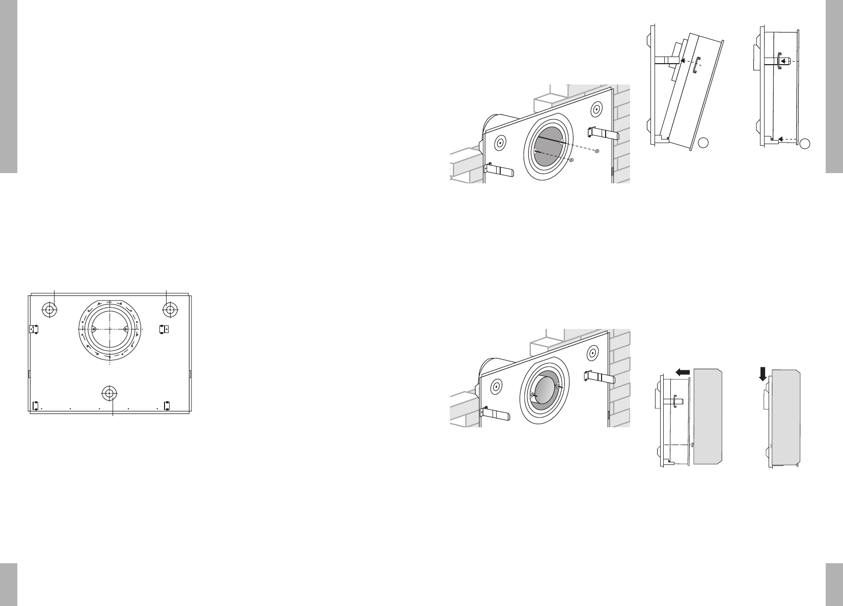
fig. 4
■ Take the internal mechanism and place the
fibreglass packing around the air inlet.
■ Place the internal mechanism with the
base resting on the lower supports.
■ Slide the internal mechanism with the
support guides around the lips on the
mounting plate.
fig. 5
■ Slide the outlet from the internal
mechanism on to the flue pipe.
■ Slide the internal mechanism horizontally
backwards until the pins on the base of the
internal mechanism engage with the
horizontal supports. Secure the internal
mechanism by screwing the support guides
tight at the top.
■ Place the casing vertically against the wall
and the mounting plate, so that the
projections fit into the slotted holes. Lower
the casing vertically.
fig. 6
connection to the gas supply
■ Avoid straining the regulator tap when
connecting. Check gas connections for
leaks. Check the operation of the heater
and explain it to the user.
INSTALLATION
4 INSTALLATION
length of inlet and outlet pipe
Wall thickness: minimum 70 mm
Length of inlet pipe: as wall thickness.
Length of outlet pipe: wall thickness + 70 mm,
maximum length 600 mm.
installing the appliance
The mounting plate supplied with this
appliance will serve as a template and as an
assembly unit for the wall vent and the
internal mechanism. Holes A, B and C in fig. 2
are for the mounting screws. The minimum
distance from the bottom of this mounting
plate to the floor must be 20 mm (295 mm from
the floor to the bottom of the vent-pipe hole).
fig. 2
The hole for the wall vent-pipe must be round
and have an internal diameter of 153 mm. It is
advisable to drill this hole or arrange for it to
be drilled.
To avoid ingress of rain this hole must be level
and must certainly not slope downwards
towards the inside.
If the heater is installed against a wall made
from combustible material, the diameter of the
wall opening must be 180 mm and a sheet of
incombustible material, containing a 153 mm
diameter hole, must be installed to cover the
entire surface behind the mounting plate. It is
advisable to mount this sheet 2 to 3 mm clear
of the wall.
When determining the place at which the
appliance is to be installed, account must also
be taken of the conditions indicated in the
section on ‘positioning’.
■ Draw the holes for the key bolts and the
opening for the wall vent pipe using the
mounting plate. Make sure that the plate is
level.
■ Drill the holes.
■ Cut the inlet pipe (largest diameter) to size.
■ Place the key bolts in the holes drilled in
the wall.
■ Secure the mounting plate to the wall.
■ Using a spirit level check that the mounting
plate is horizontal and tighten the mounting
screws.
■ Secure the inlet pipe to the flue grille.
Screw the tensioning members into the
wall grille. Then slide the grille on to the
inlet pipe.
■ Push the pipe through the hole in the wall
from the outside.