[4] (Play) - the Learn LED blinks as each step is added.
• Press [MACRO] again to exit the macro-record mode.
To clear a macro, perform the above steps without entering any functions.
EXECUTING MACROS
To execute a macro, press and release [MACRO]; its key illumination lights
for 5 seconds. While it remains lit, press an HTRM 2 key to which a macro
has previously been stored.
The corresponding macro will run; as each step executes, its “parent” Device
Selector’s key ashes lights briey; when execution is nished, the [MACRO]
key illumination goes out. Pressing any other HTRM 2 key while a macro is
executing will abort the macro. Remember that you must hold the HTRM 2
so that its infrared emitter can activate the target components.
NOTE
When a macro executes, a 1 second delay is automatically inserted
between its commands. If you need more than a 1 second delay
between particular commands—for example, to permit a component
to power up completely—you can record “empty” steps into the macro
by changing Device Selector “pages” without entering actual command
functions.
KEY ILLUMINATION TIMEOUT
The HTRM 2’s key-illumination can be set to remain lit for 0-9 seconds. The
default value is 2 seconds. To set the illumination timeout, simultaneously
press-and-hold for 3 seconds both the HTRM 2’s [DISP] and the [0-9] key,
with the digit corresponding to the desired timeout duration; the Learn
LED will ash twice to conrm the new setting. When set to zero, the
illumination will not turn on at all.
NOTES
• Key illumination is activated when one presses any HTRM 2 key.
• If HTRM 2 senses movement, key illumination is activated without
having to press a key. If HTRM 2 is shaken, key illumination is also
activated.
• Key illumination is the biggest drain on the HTRM 2’s batteries. A short
key illumination timeout will extend battery life appreciably; turning it
o altogether (set it to 0 seconds) will lengthen it still further.
CONFIGURING KEY ILLUMINATION
Keys to Press (for 3 seconds)Mode
DISP + Digit Key (0-9)Set key illumination timeout to number of
seconds corresponding to digit key. Zero turns o
the key illumination entirely.
DISP + OFFDisable light sensor. Key illumination will turn
on with any key press.
DISP + ONEnable light sensor.
DISP + ENTERSet the light sensor threshold to the current
light level.
DISP + RTNRestore all key illumination settings to the
defaults.
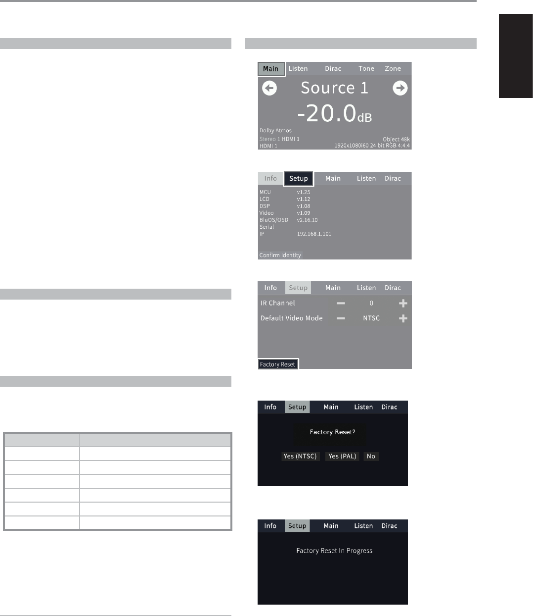
FACTORY RESET
The HTRM 2 can be reset to its factory state, deleting all learned
commands, copied and punched-through keys, macros, and other setup
information, reverting all keys to their pre-programmed library commands.
To perform a factory reset simultaneously press-and-hold for 10 seconds
the HTRM 2’s [ON] and [RTN] keys; the Learn LED will start to ash green.
Release [ON] and [RTN] before the second ash is complete; the Learn LED
will turn red, indicating the remote has been reset.
NOTE
You must release [ON] and [RTN] before the second ash goes out,
otherwise the unit will not reset; should this occur, repeat the full
procedure.
DELETE MODE
The HTRM 2 can store learned, copied, and “default library” commands on
any single key (The default library commands are the pre-programmed
NAD codes, such as the native M17 commands on the [AMP] “page.”).
You can delete commands by layers back “down” to the default library
command on any key, removing learned commands, punched-through
functions, and copied keys.
NOTE
The default library commands cannot be deleted, so you need not worry
that using Delete Mode might cause irreparable changes.
To enter Delete Mode, simultaneously press-and-hold for 3 seconds both
the desired key’s Device Selector key and the [RTN] key, until the Learn
LED turns green. Press the function key whose command you wish to
delete; the Learn LED ashes; the number of times indicates which type of
function has become active - see the table below. Press the active Device
Selector key again to exit Delete Mode.
NOTE
You may delete multiple function-key commands on the same Device
Selector “page,” but to delete from more than one Device Selector page
you must exit Delete Mode and then re-enter it on the required page.
Flashes Command Type
1 Default Library Command
2 Copied Library Command
3 Learned Command
OPERATION
USING THE HTRM 2 REMOTE CONTROL
28
ENGLISH
LOADING CODE-LIBRARIES
The HTRM 2 can store a dierent library of default NAD codes for each of
its Device Selector “pages.” If the original default library does not control
your NAD CD player, tape deck, BD player, or other component, follow the
procedure below to change the code-library.
Begin by ensuring that the component you wish the HTRM 2 to control
is plugged in and powered-up (“on,” not merely in standby). To enter the
HTRM 2s Library Mode, simultaneously press-and-hold for 3 seconds both
the desired Device Selector key and the [A/V PSET] key, until the Learn LED
turns green.
While keeping the HTRM 2 pointed toward the component, enter the rst
appropriate three-digit code-library number from the table below. Press
[OFF]. If the component turns o, press [ENTER] to accept that code-library
number and exit the Library Mode. If the component does not turn o,
enter the next three-digit code-library number from the table.
When you enter the correct number the component will turn o; press
[ENTER] to accept that code library number and exit the Library Mode.
LIBRARY
CODE
NAD PRODUCT
DESCRIPTION
LIBRARY
CODE
NAD PRODUCT
DESCRIPTION
100
Receiver/Processor (Discrete
ON/OFF)
300Tuner
101
Receiver/Processor (Toggle
ON/OFF)
301L75, L76 Tuner
102S170302L70 Tuner
103L75303L53 Tuner
104
Second Zone Commands
(Zone 2)
304L73 Tuner
3112Zone 3305C425
4112Zone 4306C445
105L70307Txx5 Series Tuner
106L76400Tape Deck B
107118401TAPE Deck A
108L53500TV 280
109L73501MR13
110Stereo Receiver / Amplier502MR20
111Stereo Second Zone503PMR45
112Txx5 Series600T535, T562, T585, M55
200CD Player601T550, L55
201CD Player (old)602T512, T531, T532, T571, T572
2025170, 5240, 5340603L70, L73 BD
2035325604L56
2045060605
T513, T514, T515, T517,
T524, T533, T534
205M5606L53 BD
SEARCH MODE
If none of the codes from the table, when entered, turns on the
component, and if you are quite sure you have followed the above
procedure completely and carefully, you may want to try the “search”
method as follows:
Enter Library Mode by simultaneously pressing-and-holding for 3 seconds
both the desired Device Selector key and the [A/V PSET] key, until the Learn
LED turns green. Now press-and-hold the HTRM 2’s [R] or [T]) key; the
remote will step through all the available codes at a rate of approximately
1 per second.
When the component turns o, immediately release the cursor key; press
[ENTER] to accept that code-library and exit the Library Mode. Try a few
commands; should you prove to have stepped past the needed code-
library, re-enter the Library Mode and use the cursor key to step back to it.
NOTE
It is possible that search mode will nd code-libraries that operate, at
least partially, some other brand (non-NAD) components. You may
certainly exploit such capabilities as you nd them. However, since we
can only ensure the completeness or accuracy of NAD code-libraries, we
cannot support the HTRM 2’s operation with other-brand components.
CHECKING CODE-LIBRARY NUMBER
You can check the current code-library on any Device Selector key as
follows. Enter Library Mode by simultaneously pressing-and-holding for
3 seconds both the desired component’s Device Selector key and the
[A/VPSET] key, until the Learn LED turns green. Press the [DISP] key; the
HTRM 2 indicates the current code-library by ashing its [DAC], [CUSTOM],
and [MACRO] keys.
For example, to indicate code-library #501, the HTRM 2 will ash [DAC] 5
times, pause, and then ash [MACRO] once. You might wish to make a note
of your components’ code-library numbers.
OPERATION
USING THE HTRM 2 REMOTE CONTROL
29
ENGLISH
SUMMARY OF THE HTRM 2 MODES
Mode Keys To Press (for 3 seconds)
Learn/Copy/Punch Through Device Key + RES Key
Delete Mode Device Key + RTN Key
Macro Record Macro Key + Function Key
Library Mode Device Key + [A/V PSET] Key
Back Light Timeout DISP Key + Digit Key
Factory Reset See “Factory Reset” above
SLEEP MODE
The Sleep Mode timer will switch the M17 to Standby mode automatically
after a preset number of minutes. Pressing the HTRM 2’s SLEEP button once
will display the setting of the sleep time increment. Pressing the HTRM 2’s
SLEEP button a second time within a 3-second period will change the
sleep time increment in 15-minute intervals, after which time the M17 will
automatically switch into Standby mode.
To adjust the sleep delay, press the HTRM 2’s SLEEP button twice; rst
to display the sleep time increment, and a second time to change the
sleep time increment. The sleep time increment and a “SLEEP” icon will
continuously display on the M17’s front panel Vacuum Fluorescent Display
(VFD). Each consecutive press increases the sleep time in 15-minute
increments from 15 to 90 minutes. To cancel the sleep mode, continue
pressing the HTRM 2’s SLEEP button until “Sleep O” displays on the VFD.
Switching the M17 to standby from either the HTRM 2’s OFF or the M17’s
STANDBY button will also cancel the sleep mode
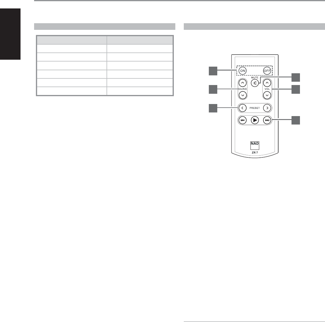
USING THE ZR 7 REMOTE CONTROL
The ZR 7 is a discrete compact remote for controlling the Zone 2 feature of the
M17. Irrespective of the main room/zone settings, the ZR 7 allows full separate
control of the Zone 2 source selection among other applicable features.
1 ON/OFF: Switch ON/OFF Zone 2.
2 SOURCE [ d/f ]: Select the active input of the NAD M17 that will be
sent out to the corresponding rear panel ZONE 2 output port.
3 MUTE: Temporarily switch OFF or restore the Zone Volume level.
4 VOLUME [ d/f ]: Increase or decrease the loudness level of selected
Zone source. This is possible only if the VOLUME setting of ZONE 2
CONTROLS is set to VARIABLE.
5 PRESET [ a/s ]: Step up or down between stored radio presets. This
control button is possible if the selected Zone is “TUNER” and the active
tuner section has stored presets. This control button is not applicable to
M17.
6 The following CD Player Zone buttons can control a compatible CD
Player. The CD Player has to be powered ON and disc loaded.
SKIP [ 9 ]: Go to the beginning of a track/le or previous track/le.
SKIP [ 0 ]: Go to the next track/le.
[ 4 ]: Start playback.
NOTE
The ZR 7 remote control will only control Zone 2 applications. Zone3
and Zone 4 could be congured and managed at the appropriate
Zone OSD menu using the front panel navigations keys as well as
the corresponding keys on the HTRM 2 remote control. The HTRM 2’s
‘CUSTOM’ device is also defaulted to Zone 2 remote control codes.
OPERATION
USING THE HTRM 2 REMOTE CONTROL
30
1
3
4
6
2
5
ENGLISH
OVERALL SPECIFICATIONS
Line Level Input
Input impedance (R and C) 56 kΩ + 220 pF
Input sensitivity 40 mV (ref. 500 mV out)
Maximum input signal>8 Vrms
Signal/Noise ratio, A-weighted>90 dB (ref. 500 mV in 500 mV out, volume set to unity gain)
>80 dB (ref. 2 V out, Volume maximum)
Channel Separation>70 dB (ref. 1 kHz/10 kHz)
Frequency response±0.3 dB (ref. 20 Hz - 20 kHz, Tone Active)
±0.3 dB (ref. 20 Hz - 20 kHz, Tone Defeat)
Frequency response (subwoofer out)10 - 200Hz (ref. -3 dB)
Output
Maximum output level>8 Vrms into 600 Ω
THD (CCIF IMD, DIM 100)<0.005% (ref. 20 Hz - 20 kHz, 2 V out)
XLR>2 Vrms
Standby mode<0.5 W
Tone Controls
Treble±10 dB at 10 kHz (ref. 2V in 2V out)
Bass ±10 dB at 100 Hz (ref. 2V in 2V out)
Connections
HDMIUp to 1080p
Optical 3 Vpp
Coaxial0.5 Vpp
EthernetRJ45 10/100 Ethernet Tx
DIMENSION AND WEIGHT
Unit dimensions (W x H x D) *435 x 156 x 386 mm
17 ¹⁄ x 6 ⁄ x 15 ¼ inches
Shipping weight17.5 kg (38.6 lbs)
* - Gross dimension includes feet, volume knob and extended rear panel terminals.
Specifications are subject to change without notice. For updated documentation and features, please check out www.NADelectronics.com for the latest information about M17.
For DTS patents, see http://patents.dts.com. Manufactured under license from DTS Licensing Limited. DTS, the Symbol, & DTS and the Symbol together, DTS:X, and the DTS:X logo are registered
All rights reserved. NAD and the NAD logo are trademarks of NAD Electronics International, a division of Lenbrook Industries Limited.
No part of this publication may be reproduced, stored or transmitted in any form without the written permission of NAD Electronics International.
While every effort has been made to ensure the contents are accurate at the time of publication, features and specifications may be subject to change without prior notice.
Libble takes abuse of its services very seriously. We're committed to dealing with such abuse according to the laws in your country of residence. When you submit a report, we'll investigate it and take the appropriate action. We'll get back to you only if we require additional details or have more information to share.
Product:
Forumrules
To achieve meaningful questions, we apply the following rules:
First, read the manual;
Check if your question has been asked previously;
Try to ask your question as clearly as possible;
Did you already try to solve the problem? Please mention this;
Is your problem solved by a visitor then let him/her know in this forum;
To give a response to a question or answer, do not use this form but click on the button 'reply to this question';
Your question will be posted here and emailed to our subscribers. Therefore, avoid filling in personal details.
Register
Register getting emails for NAD M17 V2i at:
new questions and answers
new manuals
You will receive an email to register for one or both of the options.
Get your user manual by e-mail
Enter your email address to receive the manual of NAD M17 V2i in the language / languages: English as an attachment in your email.
The manual is 4,29 mb in size.
You will receive the manual in your email within minutes. If you have not received an email, then probably have entered the wrong email address or your mailbox is too full. In addition, it may be that your ISP may have a maximum size for emails to receive.
If you have not received an email with the manual within fifteen minutes, it may be that you have a entered a wrong email address or that your ISP has set a maximum size to receive email that is smaller than the size of the manual.
The email address you have provided is not correct.
Please check the email address and correct it.
Your question is posted on this page
Would you like to receive an email when new answers and questions are posted? Please enter your email address.