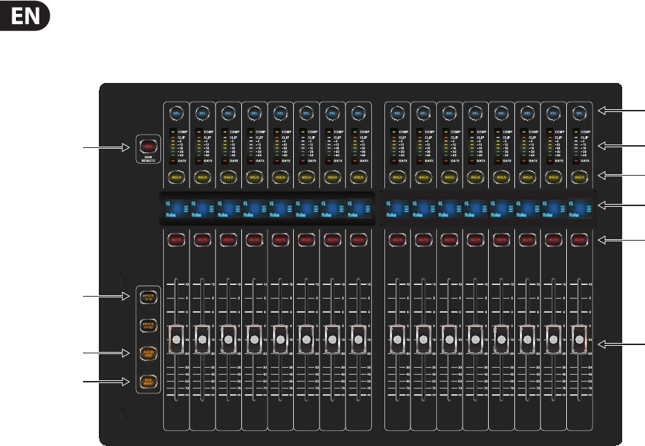
Sends On Fader = enables touch-writing a fader automation on selected track,
trackautomation mode in DAW must be ‘touch’, (latching)
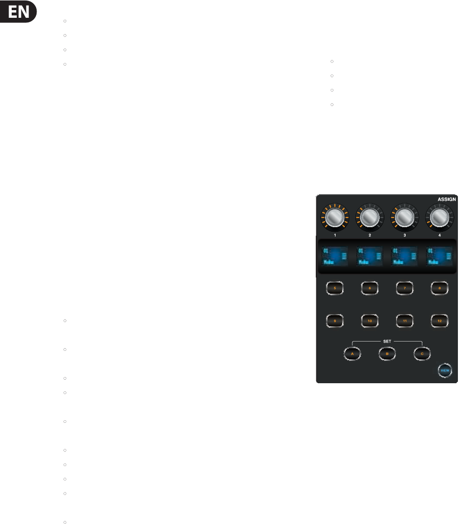
Use the layer buttons to determine the function assigned to the MUTE 1-8
buttons, the LED displays indicate that function.
•Group DCA 1-8 = allows movement of the bank selection of tracks in a DAW,
(push non-latching)
•BUS 1-8 = allows the setting of DAW tracks to ‘Record Ready’,
(pushnon-latching)
•BUS 9-16 = enables use of MUTE buttons for track mute in
theDAW,(latching)
•MTX 1-6 = enables use of MUTE buttons for transport controls in
theDAW,(latching).
MACKIE CTRL selected and Remote is enabled+active, then the group fader
section and buttons will emulate the Mackie Control Universal protocol
SELECT/SOLO 1-8 buttons will select or solo the corresponding track in the DAW,
in banks of eighttracks
Sends On Fader = enables touch-writing a fader automation on selected track,
track automation mode in DAW must be ‘touch’ or ‘latch’, (latching)
Use the layer buttons to determine the function assigned to the MUTE 1-8
buttons, the LED displays indicate that function.
•Group DCA 1-8 = allows movement of the bank selection of tracks in a DAW,
(push non-latching)
•BUS 1-8 = allows the setting of DAW tracks to ‘Record Ready’,
(push non-latching)
•BUS 9-16 = enables use of the MUTE buttons for track mute in
theDAW,(latching)
•MTX 1-6 = enables use of the MUTE buttons for transport controls in
theDAW, (latching).
50M32 DIGITAL CONSOLE User Manual
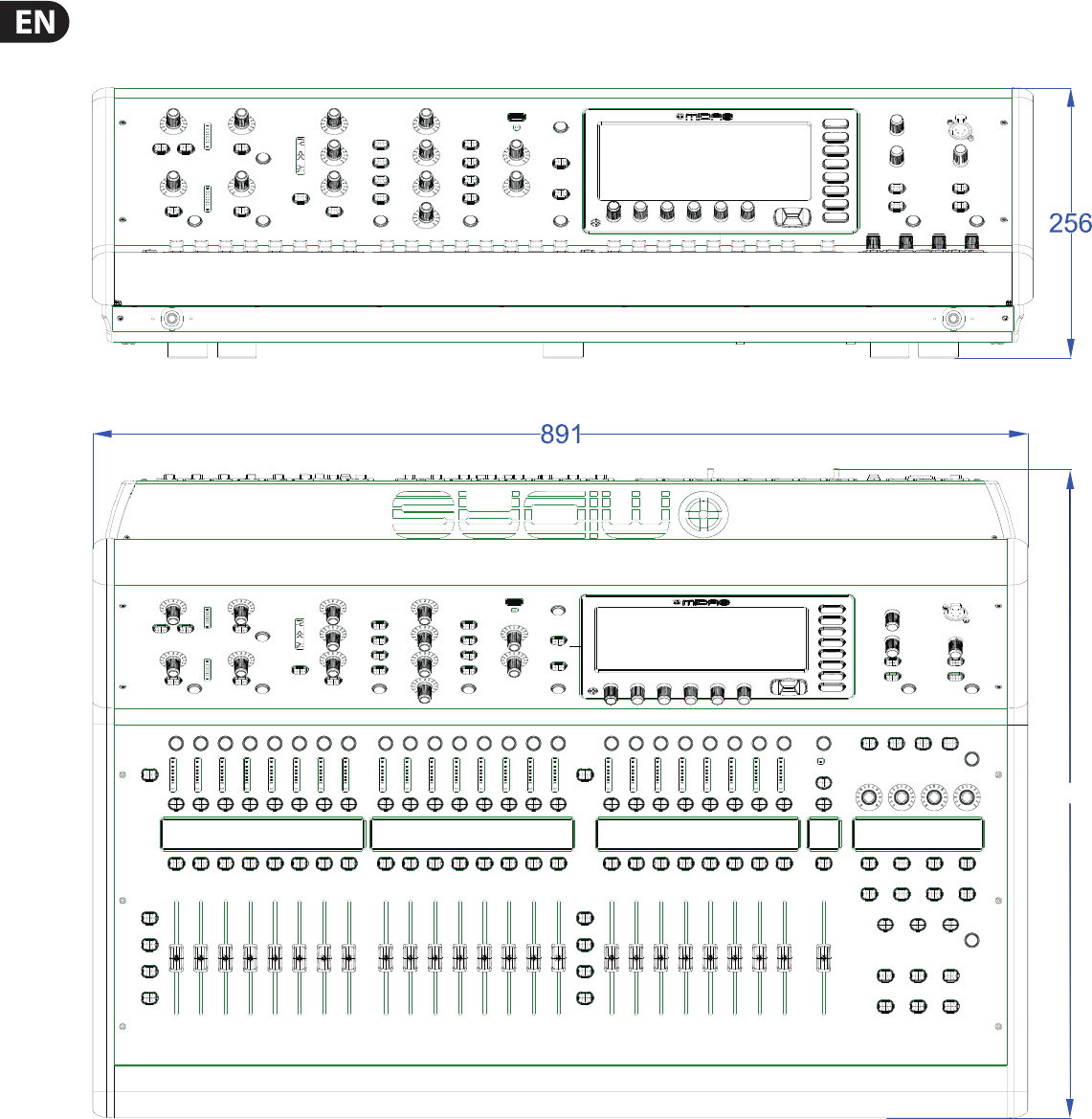
4.3 Appendix C: Dimensions
Front View
Top View
612
51M32 DIGITAL CONSOLE User Manual
Rear View
Side View
52M32 DIGITAL CONSOLE User Manual
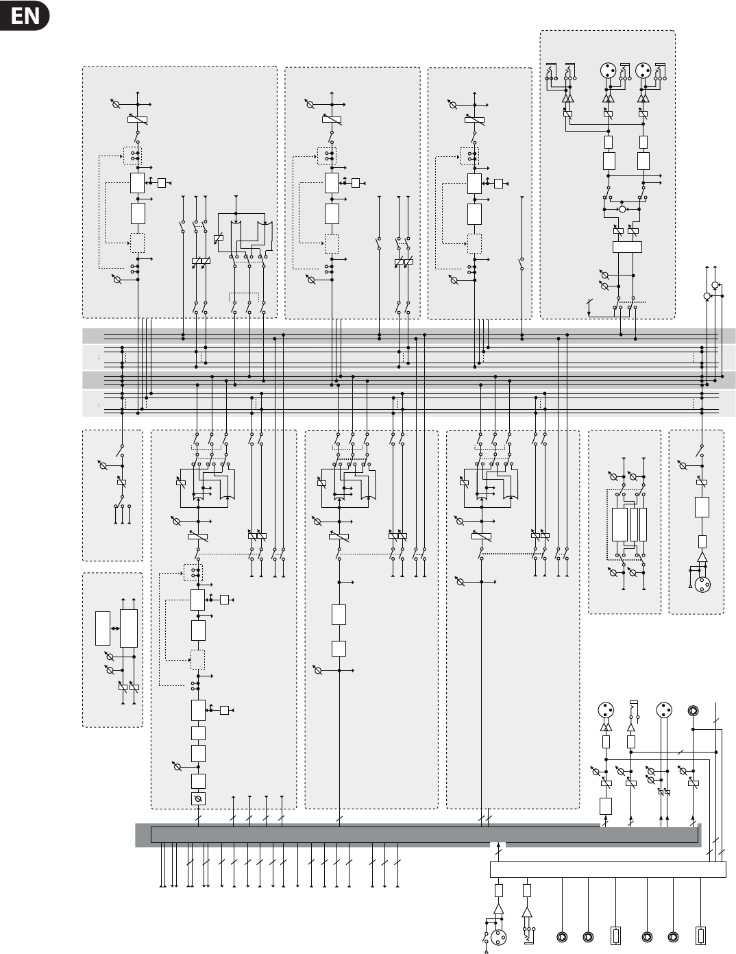
4.4 Appendix D: Block Diagram
MAIN
L R C L R
SOLOMATRIX
1 25 6
MIX BUS
1 215 16
FADER
MIX 1–16
INSERT
6-BAND
EQ
INSERT
COMP/
EXPAN
KEY-IN
Pre EQPost EQ
EQ
Pre Fader
Post Fader
Matrix 1,3,5
MUTE
MUTE
SOLO
Post Fader
Post Fader
Post Fader
Post Fader
Matrix 2,4,6
MIX 1-16
OUT
EFFECTS 1-8
EFFECT
31 BAND GEQ
31 BAND GEQ
FX OUT L
FX OUT R
FX IN L
FX IN R
USB
PLAY
USB
REC
USB RECORDER
REC
LEVEL
USB
MEMORY
USB MEMORY
RECORDER
L+C/R+C MIX
L+C OUT
R+C OUT
+
+
DSP
PATCH
USB
PLAY
USB
REC
FX 1-8 OUT (L / R)
FX 1-8 IN (L / R)
6
16
8 x 2
8 x 2
MIX 1-16 INSERT RETURN
16
MIX 1-16 INSERT SEND
16
MIX 1-16 OUT
MAIN LRC INSERT RETURN
MATRIX 1-6 INSERT RETURN
6
MATRIX 1-6 INSERT SEND
6
MATRIX 1-6 OUT
3
3
MAIN LRC INSERT SEND
3
MAIN LRC OUT
3
MAIN LRC PRE EQ OUT
PATCH CUE
MONITOR LR OUT
2
MONITOR L+C/R+C OUT
2
2
MONITOR SOURCE IN
8
AUX Returns 1–8
AUX Returns 7–8 by default on USB Play
Pre EQ
Pre EQ/Pre Fader/Post Fader/Post Pan L
Pre EQ/Pre Fader/Post Fader/Post Pan R
Pre Fader
Mix 1,3...15
Mix 2,4...16
SOLO
4BAND
EQ
ATT
Pre EQ/Pre Fader/Post Fader/Post Pan L
Pre EQ/Pre Fader/Post Fader/Post Pan R
MUTE
MUTE
FADER
LCR
PAN (LR)
PAN (LCR)
GAIN
Post Fader
Post Pan
GAIN
32
32
32
32
32
ATT
CH 1–32
LOW
CUT
GATE/
DUCK
INSERT
4-BAND
EQ
INSERT
COMP/
EXPAN
DELAY
KEY-IN
Pre EQPost EQ
EQ
Pre Fader
Mix 1,3...15
Mix 2,4...16
Pre HP/Pre Gate/Post Gate/Pre EQ/Post EQ/Pre Fader/Post Fader/Post Pan L
Pre HP/Pre Gate/Post Gate/Pre EQ/Post EQ/Pre Fader/Post Fader/Post Pan R
KEY-IN
EQ
Pre HP/Pre Gate/Post Gate/Pre EQ/Post EQ/Pre Fader/Post Fader/Post Pan L
Pre HP/Pre Gate/Post Gate/Pre EQ/Post EQ/Pre Fader/Post Fader/Post Pan R
SOLO
INSERT RETURN
INSERT SEND
PRE LOW CUT OUT
POST FADER OUT
MUTE
MUTE
FADER
LCR
PAN (LR)
PAN (LCR)
GAIN
Post Fader
Post Pan
GAIN
COMP/
EXPAN
8 x 2
STEREO FX RETURNS 1 L/R – 8 L/R
Pre Fader/Post Fader/Post Pan L
Pre Fader/Post Fader/Post Pan R
Pre Fader
Mix 1,3...15
Mix 2,4...16
SOLO
Pre Fader/Post Fader/Post Pan L
Pre Fader/Post Fader/Post Pan R
MUTE
MUTE
FADER
LCR
PAN (LR)
PAN (LCR)
GAIN
Post Fader
Post Pan
GAIN
WHITE NOISE
PINK NOISE
OSCILLATOR
SINE WAVE
GENERATE
GAIN
COMP/
EXPAN
LCR
PAN (LR)
PAN (LCR)
GAIN
GAIN
FADER
MATRIX
1-6
INSERT
INSERT
KEY-IN
Pre EQPost EQ
EQ
Pre Fader
Post Fader
MUTE
SOLO
MATRIX 1-6
OUT
Post Fader
COMP/
EXPAN
EQ
6BAND
COMP/
EXPAN
FADER
MAIN LRC
INSERT
6BAND
EQ
INSERT
COMP/
EXPAN
KEY-IN
Pre EQPost EQ
EQ
GAIN
Pre Fader
Post Fader
Matrix 1,3,5
MUTE
MUTE
SOLO
Post Fader
Post Fader
Post Fader
Matrix 2,4,6
MAIN LRC
OUT
COMP/
EXPAN
mute
mute
mute
mute
mute
mute
mute
mute
mute
stereo
mono
stereo
mute
stereo
mono
stereo
stereo
mono
stereo
stereo
mono
stereo
TALKBACK
COMP
ON
GAIN
+48V
A/D
GAIN
+
MONO
MONITOR LR OUT
DELAY
DELAY
MONITOR
D/A
PHONES
OUT
MONITOR L
OUT
D/A
MONITOR R
OUT
SOLO / SOURCE
MONITOR SOURCE IN
DIM
2
GAIN
GAIN
GAIN
PHONES
OUT
Revision 1, 2014-06-27, JD
Midas M32 Block Diagram
P16 BUS
(16ch)
D/A
OUT 1-16
D/A
AUX OUT 1-6
DELAY
GAIN
GAIN
GAIN
AES/EBU OUT
GAIN
16
6
16
6
MONITOR LR OUT
2
16
16
8
I/O
PATCH
A/D
INPUT
(1-32)
AES-50 A
(48ch IN)
AES-50 B
(48ch IN)
SLOT
(32ch IN)
AES-50 A
(48ch OUT)
AES-50 B
(48ch OUT)
SLOT
(32ch OUT)
40
AUX
RETURN
(1-6)
+48V
PHANTOM
A/D
53M32 DIGITAL CONSOLE User Manual
4.5 Appendix E: Service Information
This appendix contains routine service information for the M32 Digital Console.
Routine Maintenance
To help keep your M32 Digital Console unit in good working order and to make sure it gives you optimum performance, we recommend that you carry out the
following about once every month.
•Clean the control centre, as detailed in ‘Cleaning the control centre’ (below)
•Check controls for freedom of operation. As the controls are ‘self-cleaning’, this operation will help to prevent them from sticking
•Check the functionality of all controls, that is, control knobs, faders, pushbuttons, LEDs, etc.
•Check the functionality of equipment.
Cleaning The Control Centre
Switch o the control centre and electrically isolate it from the mains before cleaning.
Clean the control centre using a dry, lint-free cloth. Do not use harsh abrasives or solvents. When cleaning the equipment, take great care not to damage faders,
pushbuttons etc.
Cleaning a GUI Screen
Switch o the control centre and electrically isolate it from the mains before cleaning.
Carefully wipe the surface of the GUI screen with a soft, lint-free cloth or screen wipe specially designed for the purpose. When cleaning the GUI screen,
observe the following precautions:
•Avoid putting pressure on the screen
•Don’t use harsh abrasives, for example, paper towels
•Don’t apply liquids directly to the screen
•Don’t use ammonia-based cleaners and solvents, such as acetone.
If you are in doubt or have any queries about cleaning the GUI screens, contact MIDAS Technical Support.
Equipment Disposal
When this equipment has come to the end of it useful life, its disposal may come under the DIRECTIVE 2012/19/EU OF THE EUROPEAN PARLIAMENT AND OF THE COUNCIL
of 27 January 2003 on waste electrical and electronic equipment (WEEE).
Hazardous substances in WEEE contaminate water, soil and air and ultimately put at risk our environment and health. The directive aims to
minimize the impacts of WEEE on the environment during their lifetimes and when they become waste.
The WEEE directive addresses the disposal of products when they have reached the end of their life and contributes to the reduction of
wasteful consumption of natural resources. This will help to reduce pollution, and protect the environment and ourselves.
If this equipment carries a ‘crossed-out wheelie bin’ (shown left), please do not dispose of WEEE as unsorted municipal waste but collect and
dispose of in accordance with local WEEE legislation. The horizontal bar underneath indicates that the product was placed on the EU market
after 13th August 2005.
For WEEE disposal see our website at midasconsoles.com for information.
54M32 DIGITAL CONSOLE User Manual
4.6 Appendix F: Glossary
This glossary provides an explanation of the symbols, terms and abbreviations used in this manual.
5.1 surround: A surround sound system created from six channels that form
a discrete signal, which is played back over a speaker system comprising ve
speakers (three front and two rear) and a subwoofer (which is the ‘.1’ or LFE
channel). See LFE.
μ: Micro- prex symbol that represents 10-6 or one millionth.
A
A/D: Abbreviation for ‘analogue to digital’. The conversion of a continuous signal
into a numeric discrete sample sequence.
AC: Abbreviation for ‘alternating current’.
AES/EBU: Abbreviation for ‘Audio Engineering Society/European Broadcasting
Union’. See AES3.
Acoustic feedback: A sound loop existing between an audio input and
audio output that is amplied on each cycle. For example, a mic input signal
is amplied and passed to a loudspeaker. The output from the loudspeaker is
picked up the mic, which amplies it again and passes it back to the loudspeaker,
and so on.
AES3: Also known as ‘AES/EBU’, this is a serial interface for transferring digital
audio between devices.
AES50: AES digital audio engineering standard. AES50 is a high resolution,
multi-channel audio interconnection (HRMAI). Rather than a network, it is a
high-performance, point-to-point audio interconnection, although the auxiliary
data may operate as a true network, independently of the audio. HRMAI provides
a professional multi-channel audio interconnection that uses Cat 5e data cable
and is compatible with Ethernet networks.
AFL: Abbreviation for ‘after fader listen’. A function that allows the signal to be
monitored post-fader, that is, after it has been acted upon by the fader.
Algorithm: In computing, a set of instructions for accomplishing a specic task.
amp (A): Abbreviation for ‘ampere’. A unit of current.
Anti-aliasing: When referring to digital images, a technique that avoids
poor pixelation.
Area A: Primary input control area.
Area B: A secondary input control area.
Assignable controls: User-assignable controls that can be set up to operate
other functions.
Auto safe: Prevents channel from accepting scene recall.
Auto-mute: A function that automatically mutes the channel’s signal under
certain conditions.
Auto-mute group: A function that automatically mutes a number of selected
channels under certain conditions.
Automation: 1. Memorization and playback of changes made to mixer settings.
2. An area on the master bay that controls these.
Aux: Abbreviation for ‘auxiliary send’ or ‘aux send’. A designation for extra
buses, typically used for sending signal to eects, headphone amps and other
destinations. See Bus.
Aux send: See Aux.
B
Balanced audio: A type of audio connection that uses the three leads in a cable,
connector and jack as part of a phase-cancelling arrangement to boost the signal
and reduce noise.
Band: In EQ, a range of frequencies.
Bandwidth: In EQ, the width of a band, that is, the number of frequencies that
will be boosted/cut above and below a centre frequency.
Bank: A xed number of channels displayed on a GUI screen.
Bass: Lower frequencies in a signal.
Bay: One of the main control surface sections.
Bus: A pathway down which one or more signals can travel.
C
Cat 5e: A specication for a type of cable used typically for Ethernet
computer networks.
Channel: Single path taken by an audio signal (input or output) through the
control centre.
Channel strip: Row of controls in traditional analogue layout used for the
shaping of a signal.
Checkpoint: A patching data store point, created by clicking CHECKPOINT.
See Patching.
Click: A method of GUI operation, mainly for button operation and
selection purposes.
CMR: Abbreviation for ‘common mode rejection’. A measure of how well a
dierential amplier rejects a signal that appears simultaneously and in-phase at
both input terminals. CMR is usually stated as a dB ratio at a given frequency.
Comb ltering: Removal of signal components at a number of regularly
spaced frequencies.
Compressor: A dynamics processor that reduces the level of any signal
exceeding a specied threshold volume.
Condenser microphone: A high quality mic that uses a capacitor to detect
changes in the ambient air pressure, which it then converts into an electrical
signal. This type of mic requires power from a battery or external source.
Control centre: The M32’s console, comprising control surface and GUI.
Control surface: Area on the control centre that houses all of the user’s
hardware controls, such as pushbuttons, control knobs, switches etc.
Crossfade: To combine signals such that one channel or source fades out while
another fades in, but maintaining an essentially constant programme volume.
Cursor: Generally, used to describe the ‘I’-shaped pointer on the GUI that
indicates a text insertion point. See Pointer.
D
D zone: Section in the input channel strip for controlling dynamic parameters.
D/A: Abbreviation for ‘digital to analogue’. The conversion of digital data to
analogue audio.
DARS: Abbreviation for ‘digital audio reference signal’.
Dashboard: A standard GUI screen display - usually on the master bay - that
shows all channel meters (inputs, auxes, returns, masters etc.) all of the time.
DAW: Abbreviation for ‘Digital Audio Workstation’. A digital audio workstation
is an electronic system designed solely or primarily for recording, editing and
playing back digital audio.
dB: Symbol for ‘decibel’. A unit of measurement of the loudness of sound.
See dBu.
dBu: A unit of measurement of sound used in professional audio. Derived from
the decibel, where the ‘u’ stands for unloaded, this unit is an RMS measurement
of voltage based on 0.775 VRMS, which is the voltage at which you get 1 mV of
power in a 600 ohm resistor. This used to be the standard impedance in most
professional audio circuits.
DC: Abbreviation for ‘direct current’.
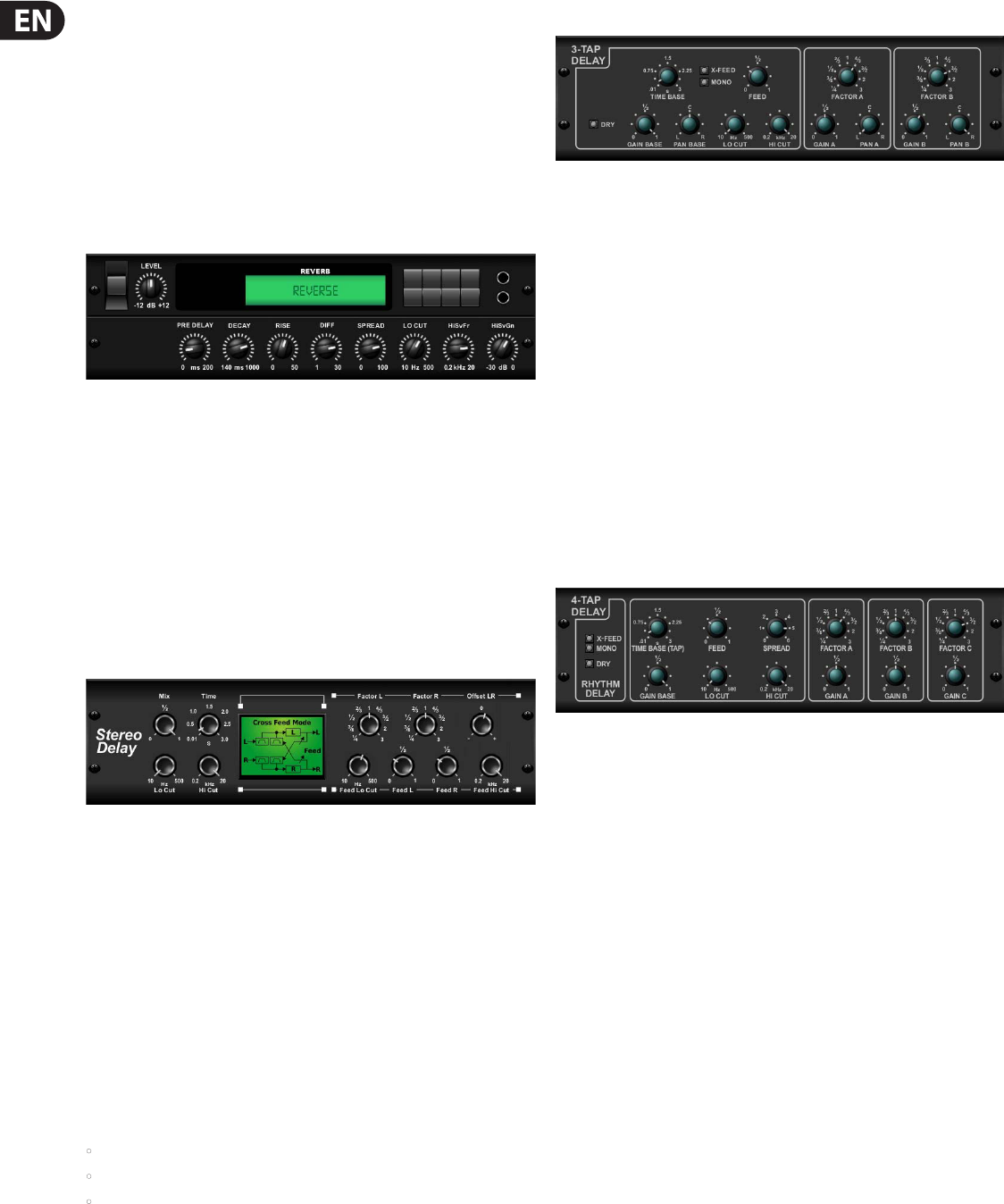
Delay: An eect by which a reproduction of a signal is played back later then
its original.
55M32 DIGITAL CONSOLE User Manual
Destination: The patch connector to which a signal is routed. See Patching.
Device: A diagram(s) in the I/O tabs representing a physical rack unit, such as a
line I/O, mic splitter, DN9696, AES50 etc. See Patching.
DI: Abbreviation for ‘direct inject’ or ‘direct injection’. Signal is plugged directly
into the audio chain without using a microphone.
DI box: Device for matching signal level impedance of a source to mixer input.
Drag: A method of GUI operation, mainly for control adjustment. Also used for
selecting blocks of patch connectors during patching.
DSP: Abbreviation for ‘digital signal processing’ or ‘digital signal processor’.
Any signal processing done after an analogue audio signal has been converted
into digital audio. Can be used to create, for example, compression, equalisation
etc., of a digital signal. A digital signal processor is a piece of equipment
specically designed for carrying out signal processing.
E
E zone: Section in the input channel strip for controlling EQ parameters.
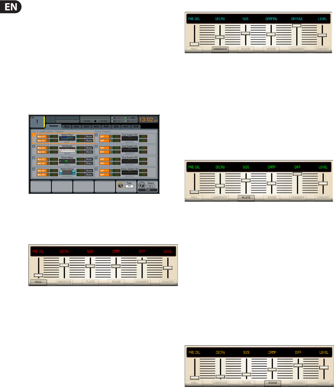
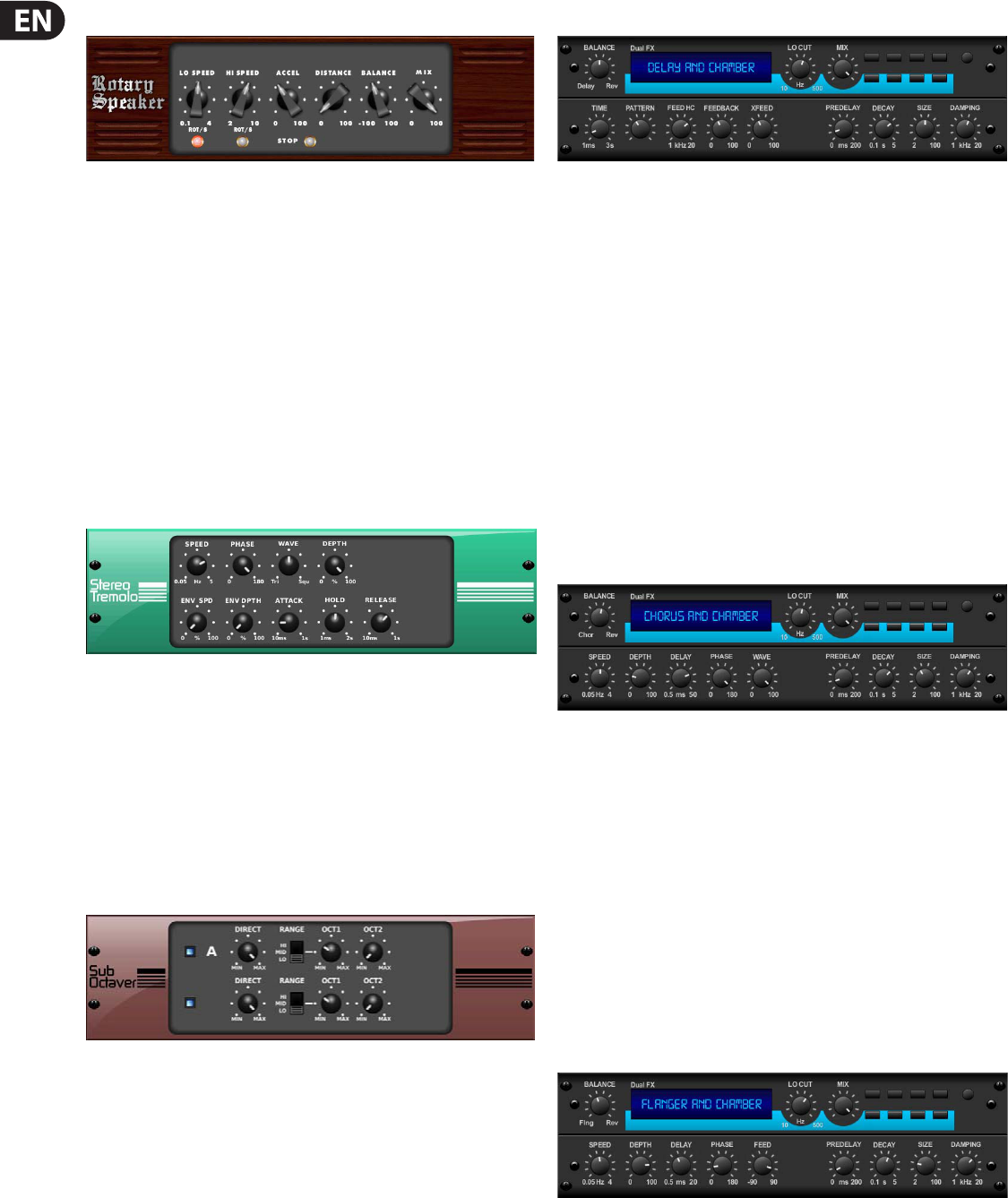
Eect: One of a number of audio processes that can be applied to a signal to
modify it, such as reverb, anging, phasing, delay etc.
Eects rack: A virtual rack of internal processors. See Virtual rack.
Envelope: 1. How a sound or audio signal varies in intensity over time.
2. The visual representation of such, usually shown on a graph in a GUI
channel strip.
EQ: Abbreviation for ‘equaliser’ or ‘equalisation’.
Equalisation: Adjusting the frequency response so that the levels
of all frequencies are equal or the same. Bass and treble controls are
equalisation controls.
EtherCon®: A cable connector for data transfer interconnections, which is more
robust than the basic RJ45.
F
Fader: Slider-type device for precise adjustment of signal level or volume of
a channel.
Fast strip: One of the strips in the input, mix and output fast zones. See Input
fast strip, Mix fast strip, Output fast strip and Fast zone.
Fast zone: An area on a bay that contains quick controls. See Input fast zone,
Mix fast zone, Output fast zone and Fast strip.
FB: Abbreviation for ‘front-back’. A term used in surround panning.
Feedback: See Acoustic feedback.
Filter: A device for removing frequencies above or below certain levels.
FOH: Abbreviation for ‘front of house’. The area in a theatre used by the public.
Used to describe a control centre being used to control the sound that the
audience will hear (and not the performers’ monitor system).
Frequency: The number of times that a sound wave’s cycle repeats within
one second.
Fricative: A consonant, such as ‘f’ or ‘s’, produced by the forcing of breath
through a constricted passage.
From section: The leftmost area of the patching screen that contains the source
patch connectors. See Patching.
G
Gain: Another term for signal level.
Gain reduction (compressor): Decrease in gain when input signal is above
threshold. See Gain.
GEQ: Abbreviation for ‘graphic equaliser’. See Graphic EQ.
GEQ rack: A virtual rack of GEQs. See Virtual rack.
Granularity: A measure of the size of components or a description of the
components comprising a system.
Graphic EQ: A form of EQ that has a number of faders for controlling the gain of
the audio signal. The faders are set at frequency bands that are evenly-spaced
according to octaves.
GUI: Abbreviation for ‘graphical user interface’.
GUI channel strip: Right section of a GUI screen that represents the processing
area of the input or output channel strip selected to the control surface.
GUI menu: A menu selectable at either GUI screen by clicking the home button
(upper-left corner).
GUI screen: One of the M32’s two screens, which comprise the GUI.
H
HPF: Abbreviation for ‘high pass lter’. A lter that removes lower frequencies
from a signal, leaving the higher frequencies unaected.
Hum: Undesirable low frequency tone present in a signal due to grounding
problems or proximity to a power source.
Hz: Symbol for ‘Hertz’. A unit of frequency equal to one cycle of a sound wave
per second.
I
I zone: Area on the master bay that contains the operator-assignable
eects controls.
I/O: Abbreviation for ‘input/output’.
ID: Abbreviation for ‘identication’.
Ident: Scale marking, or gradation, around a control knob to help indicate the
current setting and to assist in accurate adjustment.
Impedance (Z): Opposition to the ow of alternating current in a circuit,
measured in ohms.
K
Kernel: For computers, the kernel is the central component of most
operating systems.
L
LCD select button: LCD button in the input fast strips and VCA groups, used for
channel/group navigation and selection, and operator feedback.
LFE: Abbreviation for ‘low frequency eects’. Typically, the ‘.1’ in ‘5.1 surround’ is
an LFE channel.
LFO: 1. Abbreviation for Low-Frequency Oscillation, an electronic signal which is
usually below 20 Hz and creates a rhythmic pulse or sweep. This pulse or sweep
is often used to modulate synthesizers, delay lines and other audio equipment in
order to create eects used in the production of electronic music. 2. Abbreviation
for Low-Frequency Oscillator, the device itself which produces low-frequency
oscillation.
Linux: Also known as ‘Linux kernel’. Operating system kernel used by a family of
Unix-like operating systems. See kernel.
LS: Abbreviation for ‘left surround’. The left rear speaker in a 5.1
surround system.
M
MADI: Abbreviation for ‘multi-channel audio digital interface’.
Master bay: Control area for masters, automation, comms, monitoring etc.
Also contains the primary navigation zone.
Masters: The three master channels (mono and stereo left and right) in the
master bay.
MB: Abbreviation for ‘megabyte’.
MC: Abbreviation for ‘master controller’.
Meter: Visual device to indicate the level of a signal.
Meters screen: One of the GUI screens. This is the default screen of the
master bay.
56M32 DIGITAL CONSOLE User Manual
Mic: Abbreviation for ‘microphone’.
Microphone: Device for converting sound waves into audio signals.
MIDI: Acronym for ‘musical instrument digital interface’. A digital signal system
standard that facilitates integration of musical instruments, such as synthesizers
and guitars, with computers.
Mix: 1. A signal that contains a combination of signals, such as a pair of stereo
signals with numerous eects. 2. The act of creating such a combination.
3. A type of bus. See Bus.
Mix bay: Control area for outputs and groups.
Mixer: 1. A console or other device that blends input signals into composite
signals for output. 2. An engineer/technician who carries this out, especially
during a live performance.
mm: Symbol for ‘millimetre’ (one thousandth of a metre).
MON: Abbreviation for ‘monitor’, used to describe a control centre being used to
mix the signals sent to the stage monitor speakers.
Monitor: 1. Speaker(s) used for listening to a mix or live audio. 2. The act of
listening to a mix or live audio.
Monitor A: Primary monitor bus system.
Monitor B: Secondary monitor bus system.
Monitors: Control area on the master bay for monitoring the A and B
signal paths.
Mono: A single signal.
Mute: Function that allows a channel’s signal to be silenced.
Mute safe: Function that means a mute cannot be controlled by scene recall or
auto-mutes.
N
N/A: Abbreviation for ‘not applicable’.
nm: Symbol for nanometre (one billionth of a metre).
Normalise: To boost the amplitude of a digital sound so that it is as high as it
can be without clipping (0 dB).
Normalisation: An automatic process whereby the gain of all program material
is adjusted so that the peak level will just arrive at 0 dB.
Normalised connection: Also known as ‘normalled connection’. A connection
that allows a signal to pass through it when no plug is inserted in it, but breaks
the connection when a plug is inserted.
Normalising: The process of making audio les the same volume.
NVRAM: Abbreviation for ‘Non-volatile random access memory’. this is the
general name used to describe any type of RAM that retains its information when
power is switched o. For example, ash memory.
O
O/B: Abbreviation for ‘outside broadcast’.
Oct: Abbreviation for ‘octave’.
Octave: A dierence in pitch where one tone has a frequency that is double or
half of the frequency of another tone.
ohm (Ω): Unit of electrical resistance.
OpticalCon®: A cable connector for bre optic cables.
OS: Abbreviation for ‘operating system’.
OSC: Abbreviation for ‘oscillator’ or ‘oscillation’.
Out of phase: 1. A signal, being similar to another in amplitude, frequency and
wave shape, but oset in time by part of a cycle. 2. 180° out of phase or having
opposite polarity. See Phase.
Outboard: External, as in an ‘external device’.
Outboard equipment: External equipment used with the M32 Control Centre,
but that is not part of it.
Output: 1. The signal put out by a device. 2. The physical location of where a
device sends out a signal.
Output fast strip: One of 16 channel strips in the output fast zone. Provides
detailed control of the currently selected outputs. See Output fast zone.
Output fast zone: Control area for fast access to primary main output functions.
Overload: A condition where the signal level is too high.
Overview: The main view in the GUI channel strip, which contains the control
sections of the selected channel. This represents the associated channel strip on
the control surface.
Overview screen: One of the GUI screens. This is the default screen of the
mix bay.
P
PAN: Abbreviation for ‘panoramic’.
Panning: The left/right positioning of a signal across a stereo image.
Parameter: A setting whose value can be altered by the user.
Parametric EQ: A type of EQ that allows all of the parameters of equalisation to
be changed, including centre frequency, boost/cut in gain and bandwidth.
Patch: A temporary connection (physical or virtual) made between two audio
devices or inside one.
Patch connector: Any tab patching point, for example, an XLR connector, bus,
sidechain compressor etc. See Patching.
Patching: Also known as ‘soft patching’. The process of routing a channel/signal
from a source to a destination(s).
PCB: Abbreviation for ‘printed circuit board’.
PEQ: Abbreviation for ‘parametric equaliser’. See Parametric EQ.
PFL: Abbreviation for ‘pre-fade listen’. A function that allows the signal to be
monitored pre-fader, that is, before it reaches the fader.
Phantom power: The power required for the operation of a condenser
microphone when it is not supplied by internal batteries or a separate power
supply. This is supplied by the M32 Control Centre itself.
Phase: A measurement (in degrees) of the time dierence between
two waveforms.
Pitch: A continuous frequency over time. Musical interpretation of an
audio frequency.
Pitch shift: Alteration of pitch or frequency, but without adjusting tempo.
Point scene: Subdivision of a scene. See Scene.
Pointer: 1. On the GUI, the pointer is the arrow-shaped object on the screen
that moves when the user moves the trackball or external mouse. 2. On a control
knob, it is the marking that, when used in conjunction with the ident around
edge of control knob, helps to indicate the setting.
POP: Abbreviation for ‘population’.
POP group: A number of channels assigned to a group that has unfold and area
B controls. Provides an easy and quick method of manipulating and controlling
the numerous channels available on the M32 Control Centre.
Post-: The point for accessing audio just after it leaves a specic channel
component, for example, ‘post-fader’, where the audio is tapped from just after it
leaves the channel’s main level control.
Pre-: The point for accessing audio just before it reaches a specic module, for
example, ‘pre-EQ’, where the audio is tapped from just before it gets to a channel
strip’s EQ.
Primary navigation zone: Area in the master bay for mix and master bay GUI
screen navigation and control. Also has a screen access section for fast access to
GUI menu options.
Processing area: A display in a GUI channel strip showing a specic control
section. Accessed from the channel’s overview display. See Overview.
PSU: Abbreviation for ‘power supply unit’.
57M32 DIGITAL CONSOLE User Manual
Psychoacoustics: The study of the perception of sound, that is, how we
listen, our psychological responses and the physiological eects on the human
nervous system.
Pschycoacoustic noise: Noise that aects the physiology of the listener.
Q
Quick access button: Button for navigation/ selection of a channel/bus/
processing area.
R
RAM: Abbreviation for ‘Random access memory’.
Return: Auxiliary return or aux return. An extra input used for receiving a signal
from the output of an internal or external eect processor. See Bus.
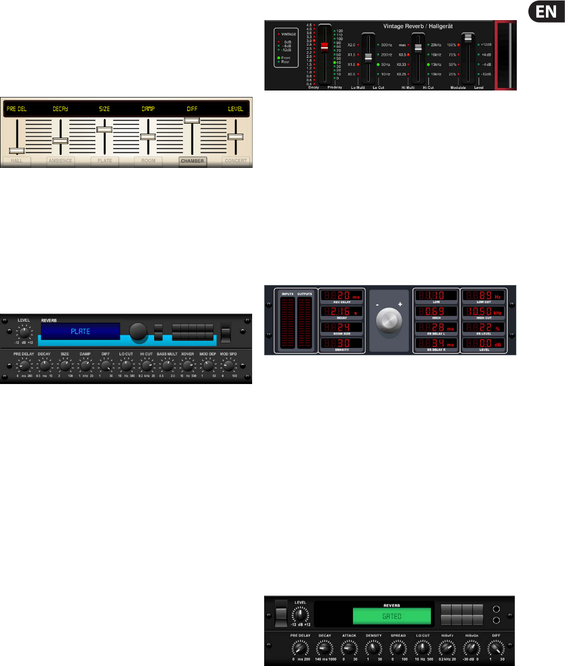
Reverb: An eect where the ambience of a physical space is simulated. This is
done by copying a signal and replaying at regular intervals at ever decreasing
levels. The intervals are so close that each copy is not heard individually.
RMS: Abbreviation for ‘root-mean-square’. The square root of the mean of the
sum of the squares. Commonly used as the eective value of measuring a sine
wave’s electrical power. A standard in amplier measurements. The eective
average value of an AC waveform.
RS: Abbreviation for ‘right surround’. The right-hand rear speaker in a 5.1
surround system.
S
s: Symbol for ‘second’. A unit of time.
Scene: In automation, a set of mix settings for a particular part of a performance,
for example, a play or song.
Sibilance: Energy from a voice, centred around 7 kHz, and caused by
pronouncing ‘s’, ‘sh’ or ‘ch’ sounds.
Side chain: A special circuit that diverts a proportion of the main signal so that
it can be processed, as required. Compressors use the side chain to derive their
control signals.
Signal ow: The path of a signal from one place to another.
SIP™: Abbreviation for ‘solo in place’.
SIS: Abbreviation for ‘spatial imaging system’. Combines a central loudspeaker
cluster with a left-right system to form three discrete sound channels.
Snapshot: A captured group of mixer settings that reect the state of the mixer
at a particular moment within a performance. This snapshot can then be recalled
at the required moment in the performance/playback.
Solo: During monitoring, the isolation of one signal by silencing all other signals.
Source: The patch connector from which a signal is patched. See Patching.
SPL: Abbreviation for ‘sound pressure level’. Given in decibels (dB), SPL is an
expression of loudness or volume.
Splash screens: The GUI display during power up.
SRC: Abbreviation for ‘sample rate converter’.
SSD: Abbreviation for ‘solid-state disk’. Data storage device that uses non-
volatile memory to store data. Quicker than the conventional hard disk and less
susceptible to the failures associated with hard disk drives.
Status indicator: A device specically designed to show the condition of
something. For example, an LED that shows whether a pushbutton is on or o, or
a meter showing the level of a signal.
Stereo: Two separate channels, left and right, used to give the listener the
perception of where the noise is coming from. Usually used with music to give a
fuller, more natural sound.
Stereo image: The perception of the dierent sound sources coming from far
left, far right or anywhere in between.
Surround: Audio that has more that two speaker locations and, therefore,
more than two channels. Also commonly termed ‘surround sound’.
Synchronisation (sync): Coordination of timing between devices.
T
Tab: A ‘sheet’ in the From and To sections that contains a specic group of patch
connectors. See Patching.
TFT: Abbreviation for ‘thin lm transistor’.
Threshold: Level at which dynamics processing will begin to operate.
Tie line: A dedicated connection between two systems, typically between FOH
and MON positions.
To section: The rightmost area of the Patching screen that contains the
destination patch connectors. See Patching.
Tooltip: The information box that appears next to the pointer when it passes
over or pauses on items on certain GUI screens, such as the channels on the
Overview and Patching screens.
Touchpad: Also known as ‘trackpad’. An input device on a laptop PC for
controlling the on-screen pointer.
Track: Single stream of recorded audio data.
Trackball: Device, located in the primary navigation zone, for GUI screen
navigation and control of the mix and master bays.
Treble: Higher frequencies in a signal.
TW: Abbreviation for ‘twin-wire’.
U
Unbalanced audio: A type of audio connection that utilises only two of the
leads of a cable, connector and jack.
Unfold: Navigates the input channels of a group to the input bays.
USB: Abbreviation for ‘universal serial bus’. A ‘plug and play’ interface that
provides a fast connection between a computer and peripherals, such as
keyboards, printers, scanners, digital cameras etc.
V
VCA: Abbreviation for ‘variable control association’ (also ‘voltage
controlled amplier’).
VCA fader: The fader control of a VCA group.
VCA group: A group of channels that are controlled globally, such as via
their group’s fader and other controls. Provides an easy and quick method of
manipulating and controlling the numerous channels available on the M32
Control Centre.
VGA: Abbreviation for ‘video graphics array’. A graphics display system for PCs
developed by IBM.
Virtual rack: A traditional 19” rack, represented on the GUI. A virtual rack will,
typically, contain internal devices, such as eects and GEQs.
Volt (V): A unit of electrical potential dierential or electromotive force.
Volume: General term for a signal’s loudness.
W
Window: A small self-contained panel that appears on the GUI, usually after
selection of a specic control. Typically, contains a number of user-selectable
options or information in the form of a message or prompt.
X
X-over: Abbreviation for ‘crossover’.
XLR connector: High-quality three-pin audio connector, which is also used for
AES/EBU digital audio connections.
58M32 DIGITAL CONSOLE User Manual
Other important information
1. Register online. Please register your new
MUSIC Group equipment right after you purchase it by
visiting midasconsoles. com. Registering your purchase
using our simple online form helps us to process your repair
claims more quickly and eciently. Also, read the terms and
conditions of our warranty, ifapplicable.
2. Malfunction. Should your MUSICGroup
Authorized Reseller not be located in your vicinity, you
may contact the MUSIC Group Authorized Fulller for your
country listed under “Support” at midasconsoles. com.
Shouldyour country not be listed, please check if your
problem can be dealt with by our “OnlineSupport” which
may also be found under “Support” at midasconsoles. com.
Alternatively, please submit an online warranty claim at
midasconsoles. com BEFORE returning theproduct.
3. Power Connections. Before plugging the unit
into a power socket, please make sure you are using the
correct mains voltage for your particular model. Faultyfuses
must be replaced with fuses of the same typeand rating
without exception.
1. Registro online. Le recomendamos que registre
su nuevo aparato MUSIC Group justo después de su compra
accediendo a la página web midasconsoles. com. Elregistro
de su compra a través de nuestro sencillo sistema online nos
ayudará a resolver cualquier incidencia que se presente a la
mayor brevedad posible. Además,aproveche para leer los
términos y condiciones de nuestra garantía, si es aplicable
en sucaso.
2. Averías. En el caso de que no exista un distribuidor
MUSIC Group en las inmediaciones, puede ponerse en
contacto con el distribuidor MUSIC Group de su país,
queencontrará dentro del apartado “Support” de nuestra
página web
midasconsoles. com
. En caso de que su país no
aparezca en ese listado, acceda a la sección “Online Support”
(quetambiénencontrará dentro del apartado “Support” de
nuestra páginaweb) y compruebe si su problema aparece
descrito y solucionado allí. De forma alternativa, envíenos a
través de la página web una solicitud online de soporte en
periodo de garantía ANTES de devolvernos el aparato.
3. Conexiones de corriente. Antes de enchufar
este aparato a una salida de corriente, asegúrese de que
dicha salida sea del voltaje adecuado para su modelo
concreto. En caso de que deba sustituir un fusible quemado,
deberá hacerlo por otro de idénticas especicaciones,
sinexcepción.
1. Enregistrez-vous en ligne. Prenez le temps
d’enregistrer votre produit MUSIC Group aussi vite que
possible sur le site Internet midasconsoles. com. Le fait
d’enregistrer le produit en ligne nous permet de gérer
les réparations plus rapidement et plus ecacement.
Prenezégalement le temps de lire les termes et conditions
de notre garantie.
2. Dysfonctionnement. Si vous n’avez pas de
revendeur MUSIC Group près de chez vous, contactez le
distributeur MUSIC Group de votre pays: consultez la liste
des distributeurs de votre pays dans la page “Support” de
notre site Internet midasconsoles. com. Si votre pays n’est
pas dans la liste, essayez de résoudre votre problème avec
notre “aideen ligne” que vous trouverez également dans la
section “Support” du site midasconsoles. com. Vous pouvez
également nous faire parvenir directement votre demande
de réparation sous garantie par Internet sur le site
midasconsoles. com AVANT de nous renvoyer le produit.
3. Raccordement au secteur. Avant de relier
cet équipement au secteur, assurez-vous que la tension
secteur de votre région soit compatible avec l’appareil.
Veillez à remplacer les fusibles uniquement par des modèles
exactement de même taille et de même valeur électrique
— sans aucune exception.
1. Online registrieren. Bitte registrieren Sie
Ihr neues MUSIC Group-Gerät direkt nach dem Kauf auf
der Website midasconsoles. com. Wenn Sie Ihren Kauf
mit unserem einfachen online Formular registrieren,
können wir Ihre Reparaturansprüche schneller und
ezienter bearbeiten. Lesen Sie bitte auch unsere
Garantiebedingungen, fallszutreend.
2. Funktionsfehler. Sollte sich kein MUSICGroup
Händler in Ihrer Nähe benden, können Sie den
MUSICGroup Vertrieb Ihres Landes kontaktieren, derauf
midasconsoles. com unter „Support“ aufgeführt ist.
Sollte Ihr Land nicht aufgelistet sein, prüfen Sie bitte,
ob Ihr Problem von unserem „Online Support“ gelöst
werden kann, den Sie ebenfalls auf midasconsoles. com
unter „Support“ nden. Alternativ reichen Sie bitte Ihren
Garantieanspruch online auf midasconsoles. com ein,
BEVOR Sie das Produktzurücksenden.
3. Stromanschluss. Bevor Sie das Gerät an
eine Netzsteckdose anschließen, prüfen Sie bitte, obSie
die korrekte Netzspannung für Ihr spezielles Modell
Libble takes abuse of its services very seriously. We're committed to dealing with such abuse according to the laws in your country of residence. When you submit a report, we'll investigate it and take the appropriate action. We'll get back to you only if we require additional details or have more information to share.
Product:
Forumrules
To achieve meaningful questions, we apply the following rules:
First, read the manual;
Check if your question has been asked previously;
Try to ask your question as clearly as possible;
Did you already try to solve the problem? Please mention this;
Is your problem solved by a visitor then let him/her know in this forum;
To give a response to a question or answer, do not use this form but click on the button 'reply to this question';
Your question will be posted here and emailed to our subscribers. Therefore, avoid filling in personal details.
Register
Register getting emails for Midas M32 at:
new questions and answers
new manuals
You will receive an email to register for one or both of the options.
Get your user manual by e-mail
Enter your email address to receive the manual of Midas M32 in the language / languages: English as an attachment in your email.
The manual is 9,9 mb in size.
You will receive the manual in your email within minutes. If you have not received an email, then probably have entered the wrong email address or your mailbox is too full. In addition, it may be that your ISP may have a maximum size for emails to receive.
The manual is sent by email. Check your email
If you have not received an email with the manual within fifteen minutes, it may be that you have a entered a wrong email address or that your ISP has set a maximum size to receive email that is smaller than the size of the manual.
The email address you have provided is not correct.
Please check the email address and correct it.
Your question is posted on this page
Would you like to receive an email when new answers and questions are posted? Please enter your email address.