TABLE OF CONTENTS
IMPORTANT ............................................................. i
EXPLICIT DEFINITIONS .......................................... i
PRECAUTIONS ........................................................ i
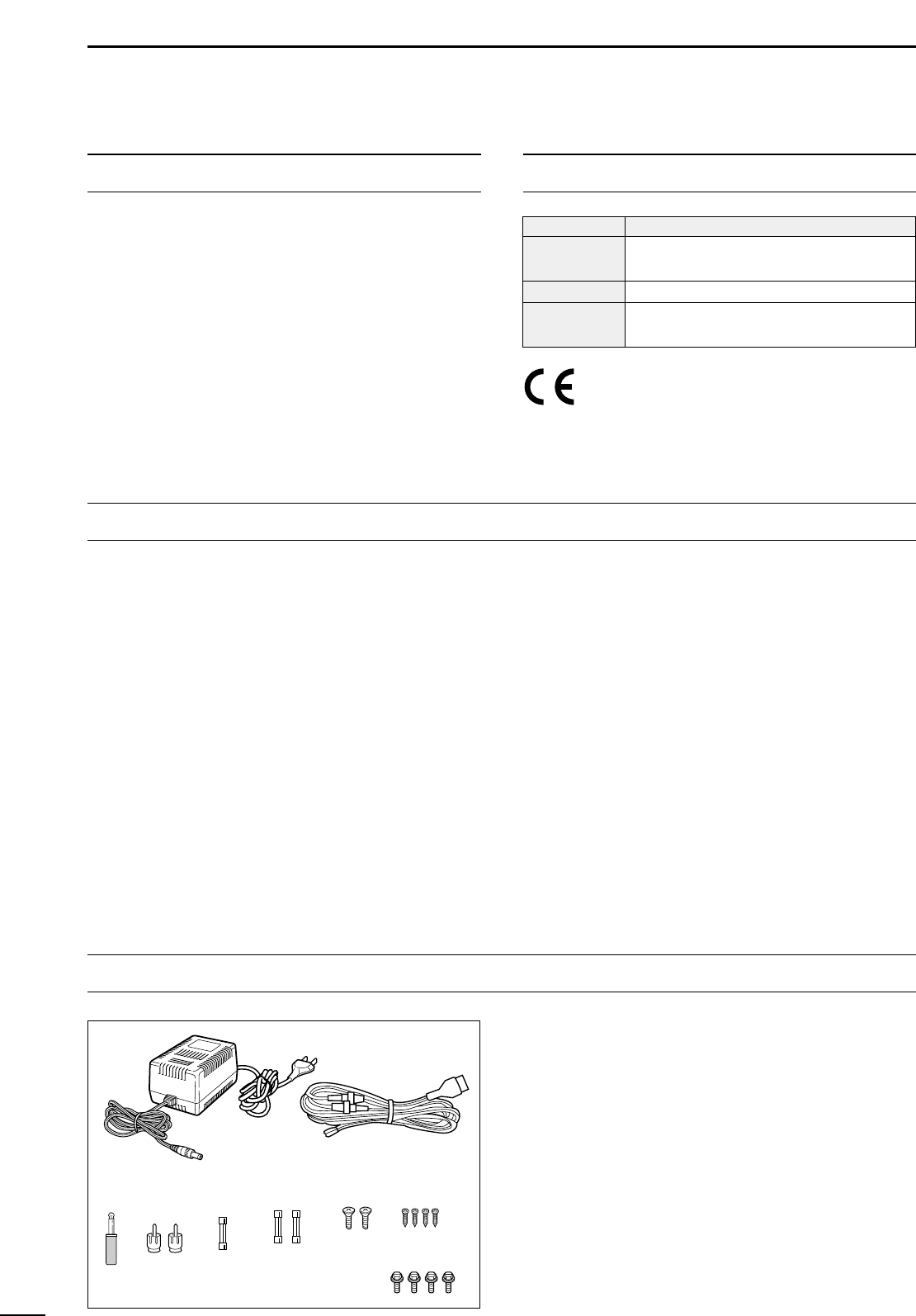
UNPACKING............................................................. i
TABLE OF CONTENTS ............................................ ii
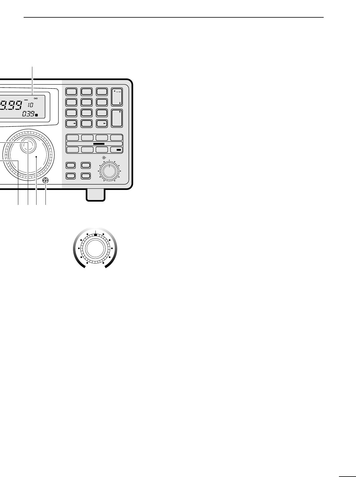
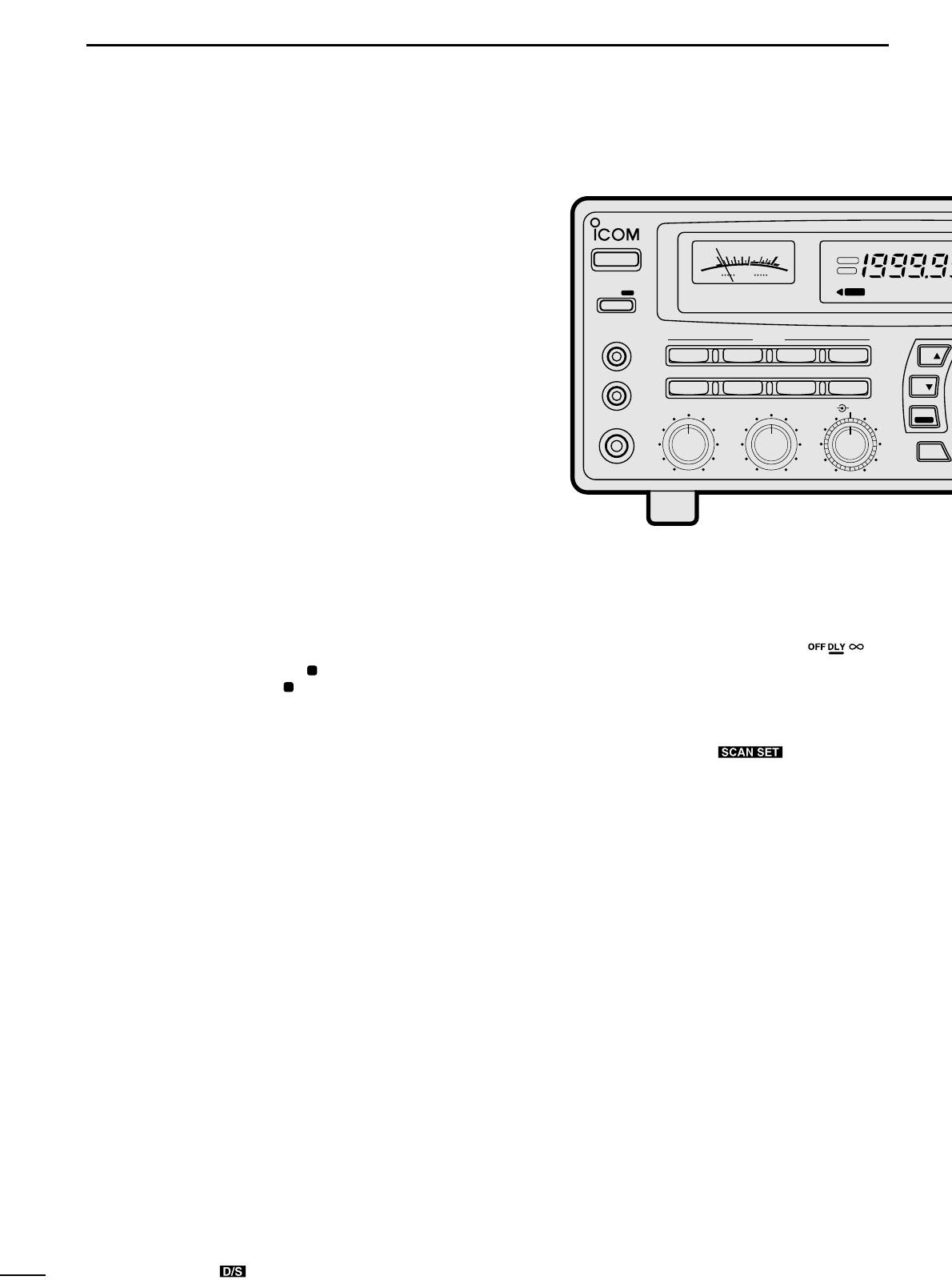
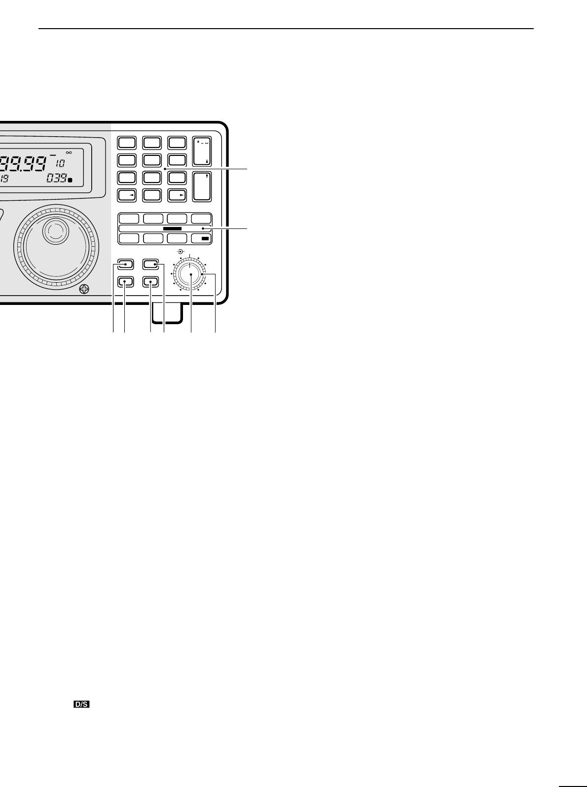
1 PANEL DESCRIPTION .....................................1–6
■ Front panel ................................................................... 1
■ Rear panel ...................................................................5
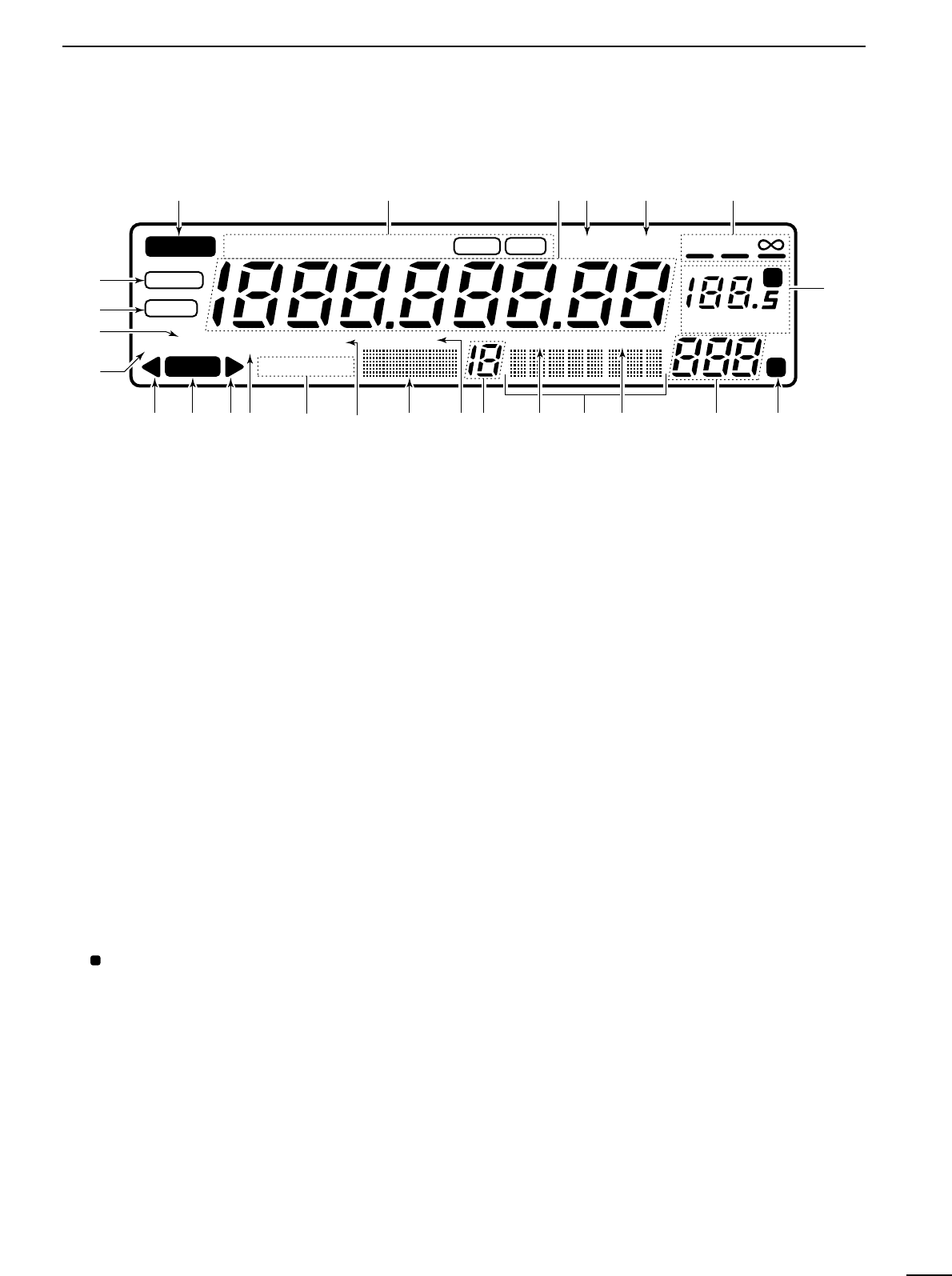
■ Function display ...........................................................6
2 CONNECTIONS ..............................................7–10
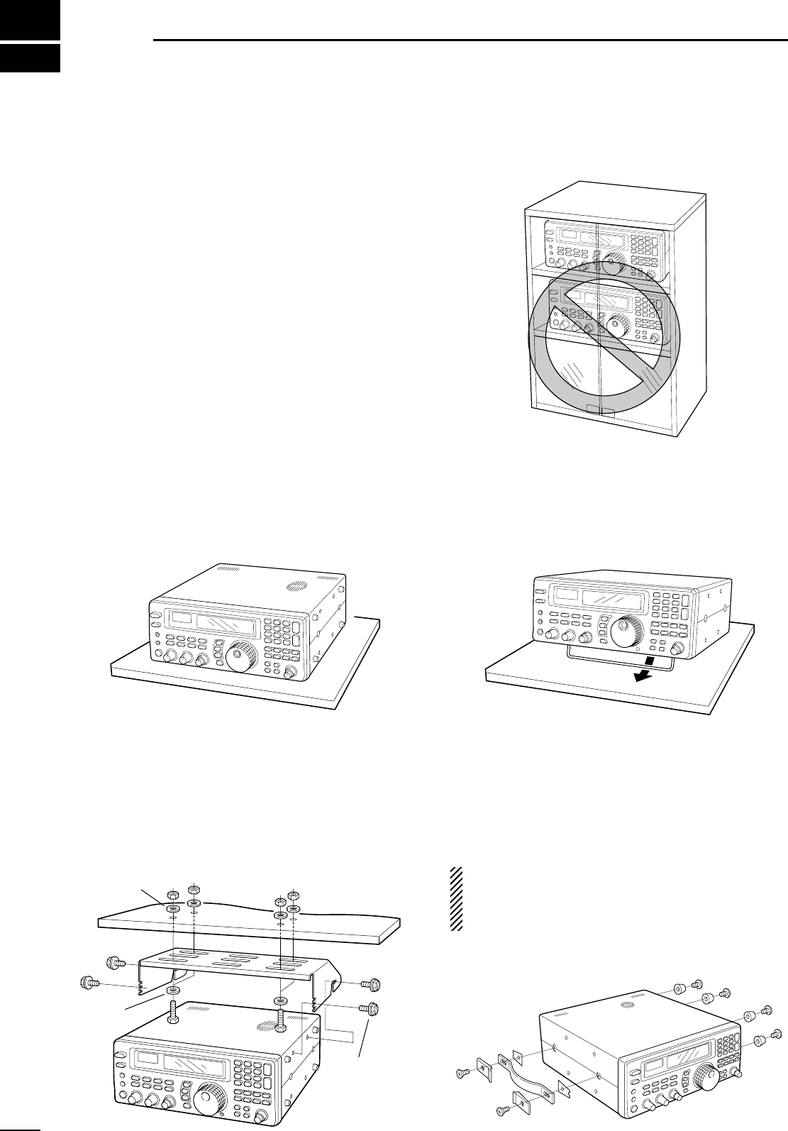
■ Mounting installation ....................................................7
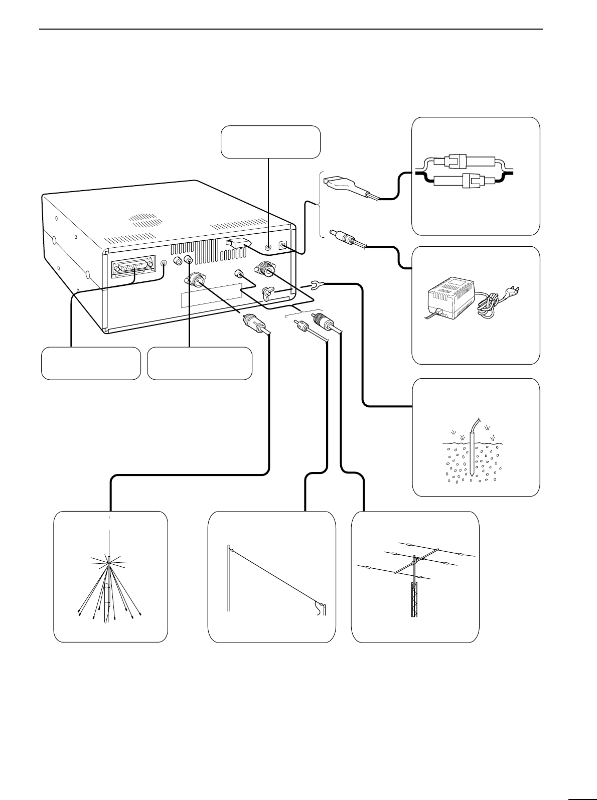
■ Required connections ..................................................8
■ Antenna connection .....................................................9
■ Grounding ....................................................................9
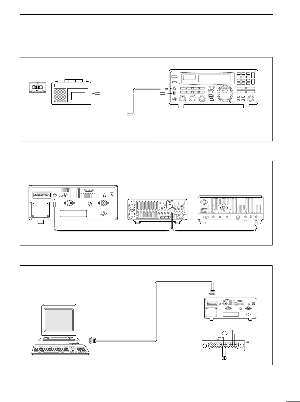
■ Tape recorder connections ........................................ 10
■ Transceive function .................................................... 10
■ Connecting to a PC ................................................... 10
■ Data demodulation terminal ....................................... 10
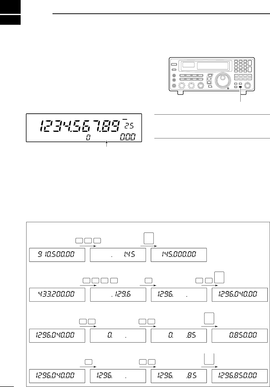
3 FREQUENCY SETTING ................................ 11–12
■ Read me first .............................................................. 11
■ Using the keypad ....................................................... 11
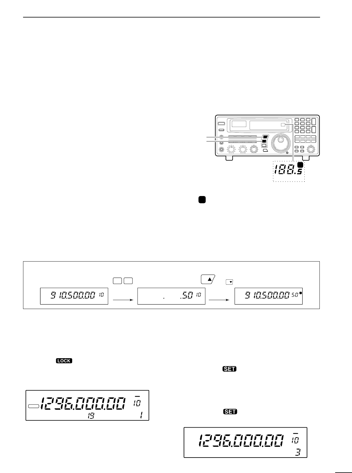
■ Using the main dial ....................................................12
■ Lock function .............................................................. 12
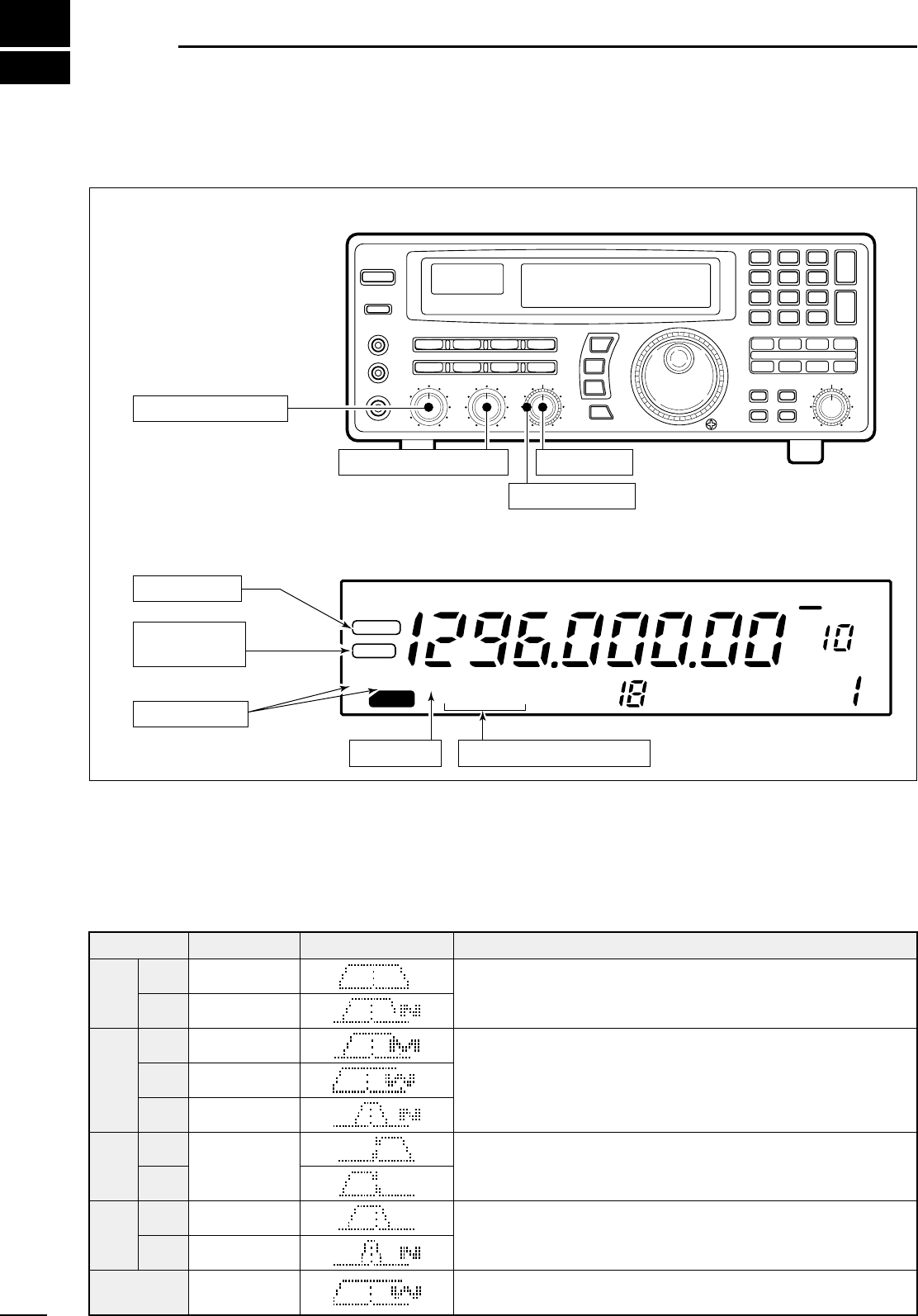
4 RECEIVE FUNCTIONS ................................. 13–16
■ Initial settings .............................................................13
■ Mode selection ........................................................... 13
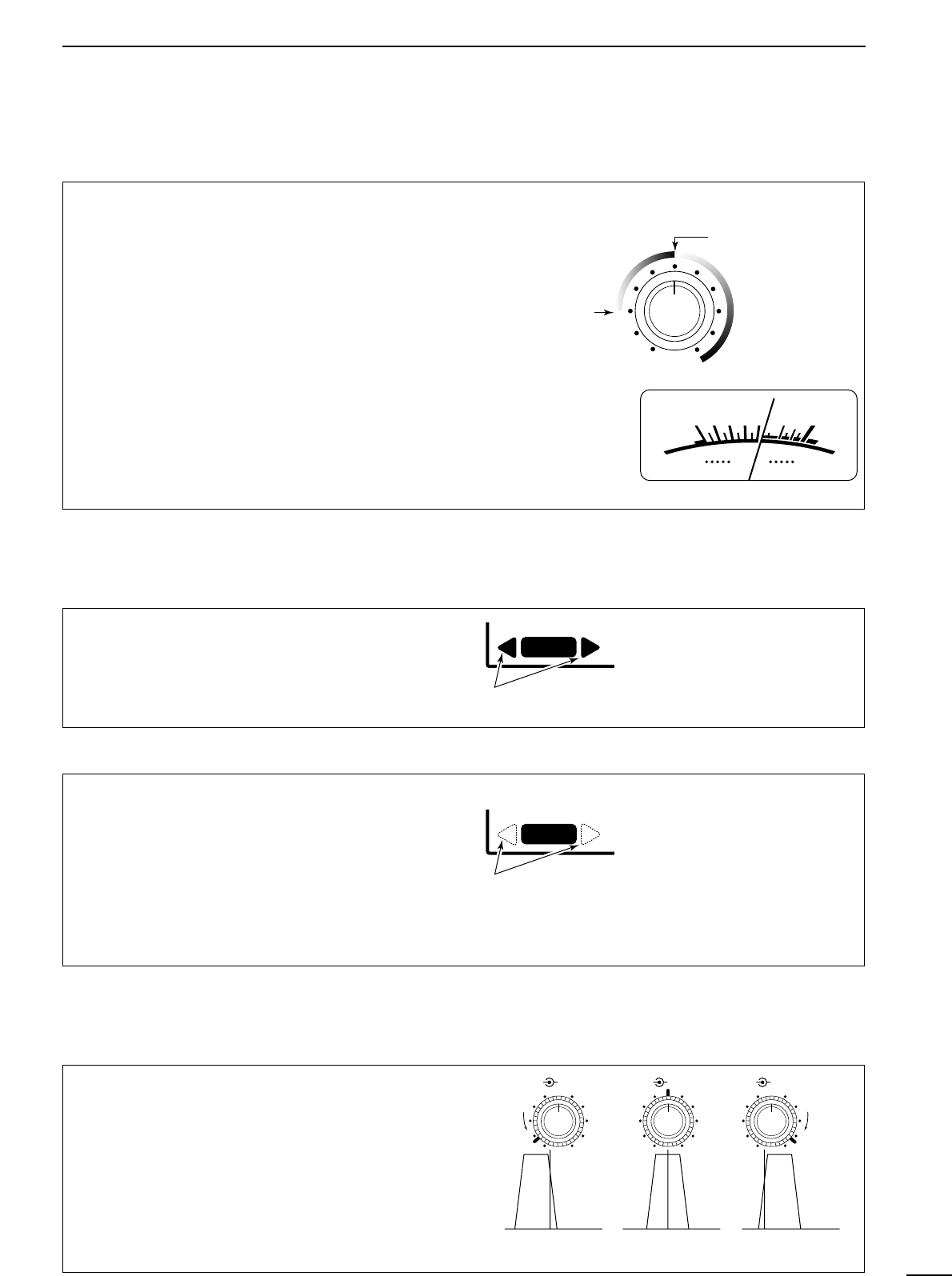
■ Squelch function ........................................................ 14
■ Functions for FM ........................................................ 14
■ Functions for SSB/CW ............................................... 14
■ Data communications .................................................16
5 MEMORY CHANNELS ..................................17–22
■ General ......................................................................17
■ Bank selection ........................................................... 17
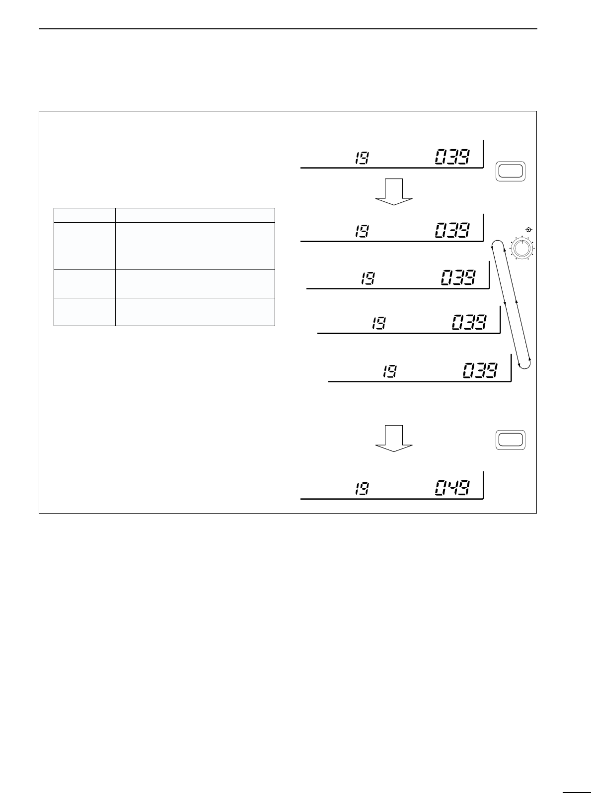
■ Channel selection ...................................................... 18
■ Programming .............................................................19
■ Copy and paste (memory editing) .............................. 19
■ Clearing ..................................................................... 19
■ Channel/bank names ................................................. 20
■ Assigning channels numbers .....................................21
6 SCANS ..........................................................23–28
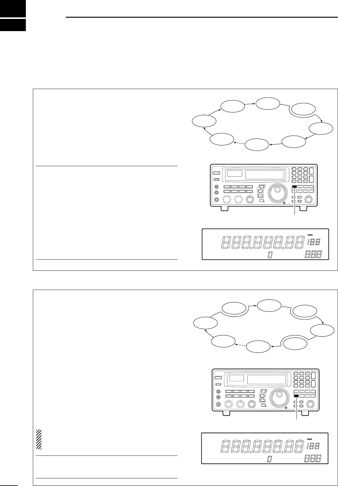
■ Operation ...................................................................23
■ Mode select function .................................................. 25
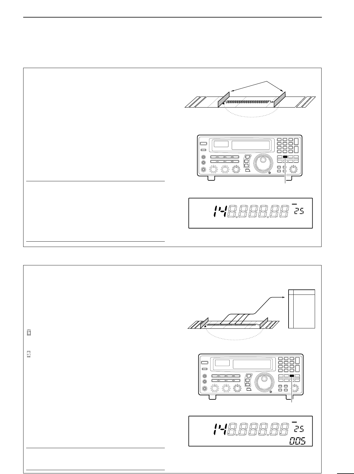
■ Specifying skip channel and frequency ..................... 25
■ Automatic bank limit/skip functions ............................ 26
■ Voice scan control function ........................................ 26
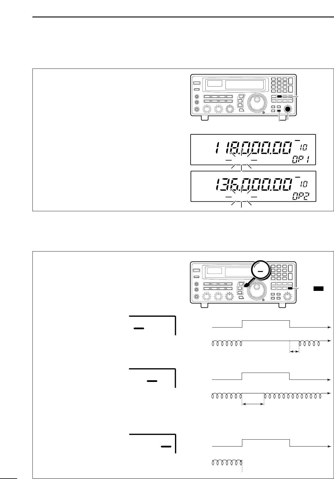
■ Programming scan edge frequencies ........................ 27
■ Scan speed/delay functions ....................................... 27
7 SLEEP TIMER .....................................................29
8 SET MODE ..........................................................30
■ General ......................................................................30
■ Quick set mode items ................................................ 31
■ Initial set mode items ................................................. 31
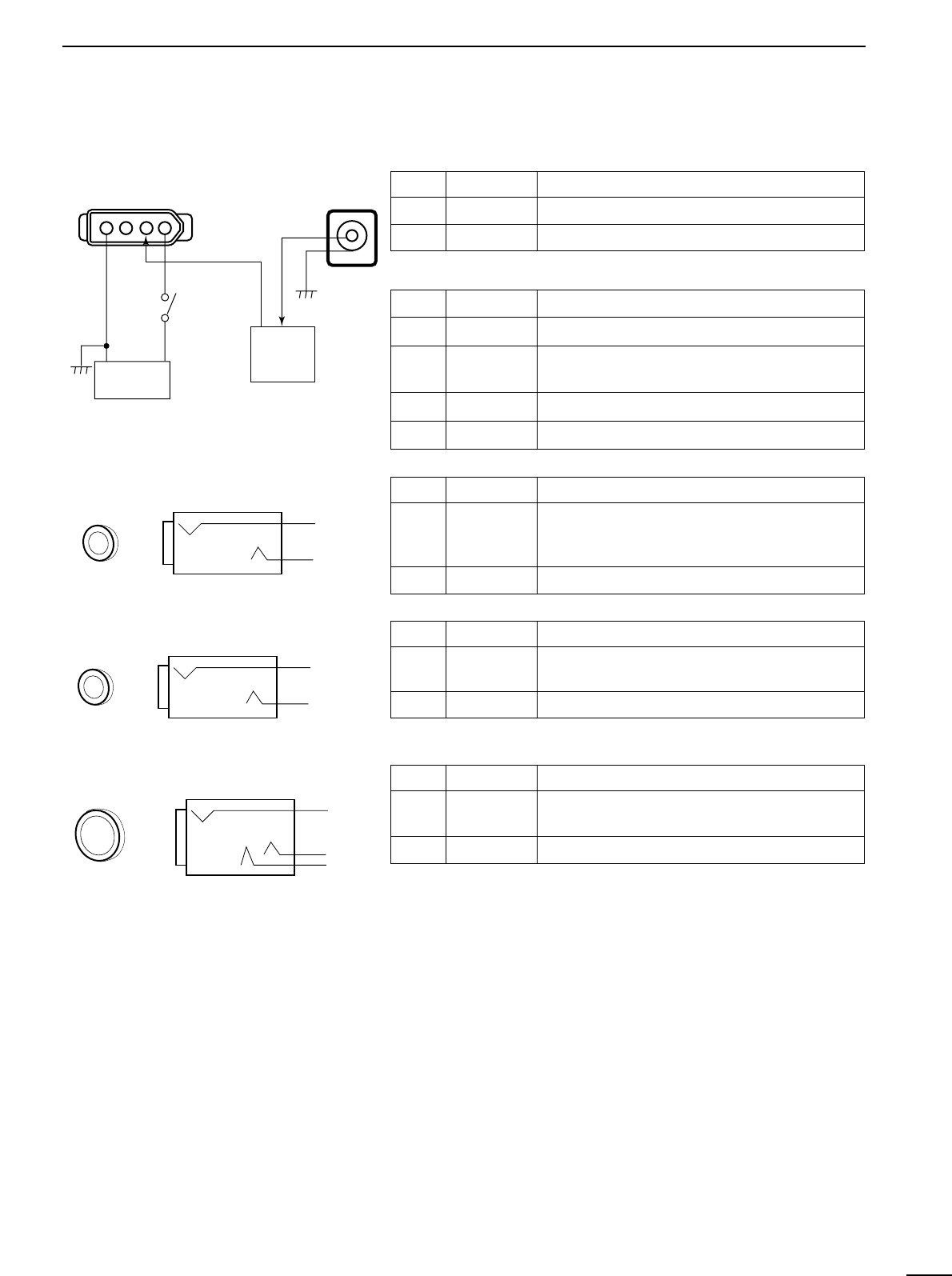
9 CONNECTOR INFORMATION ...................... 33– 34
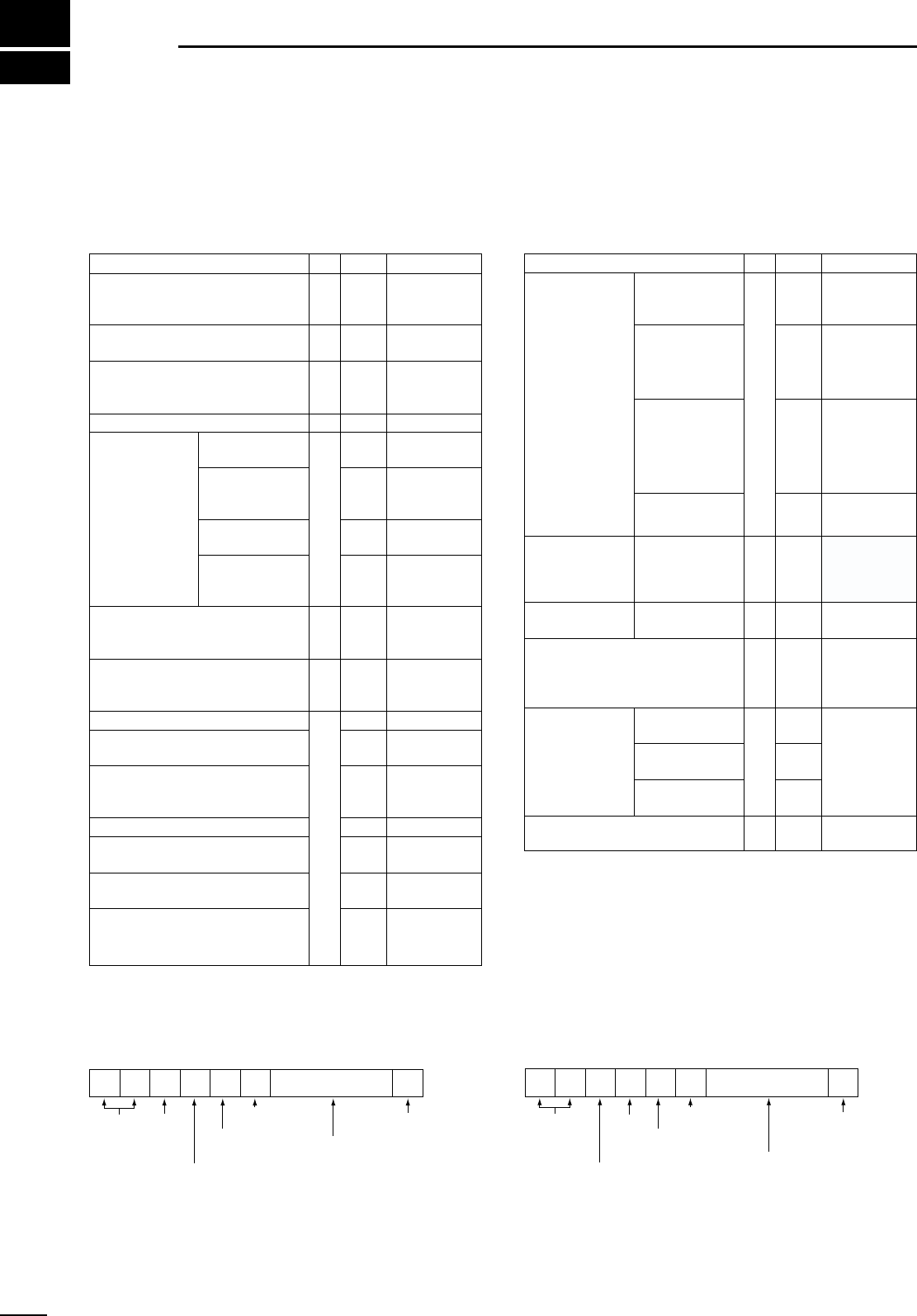
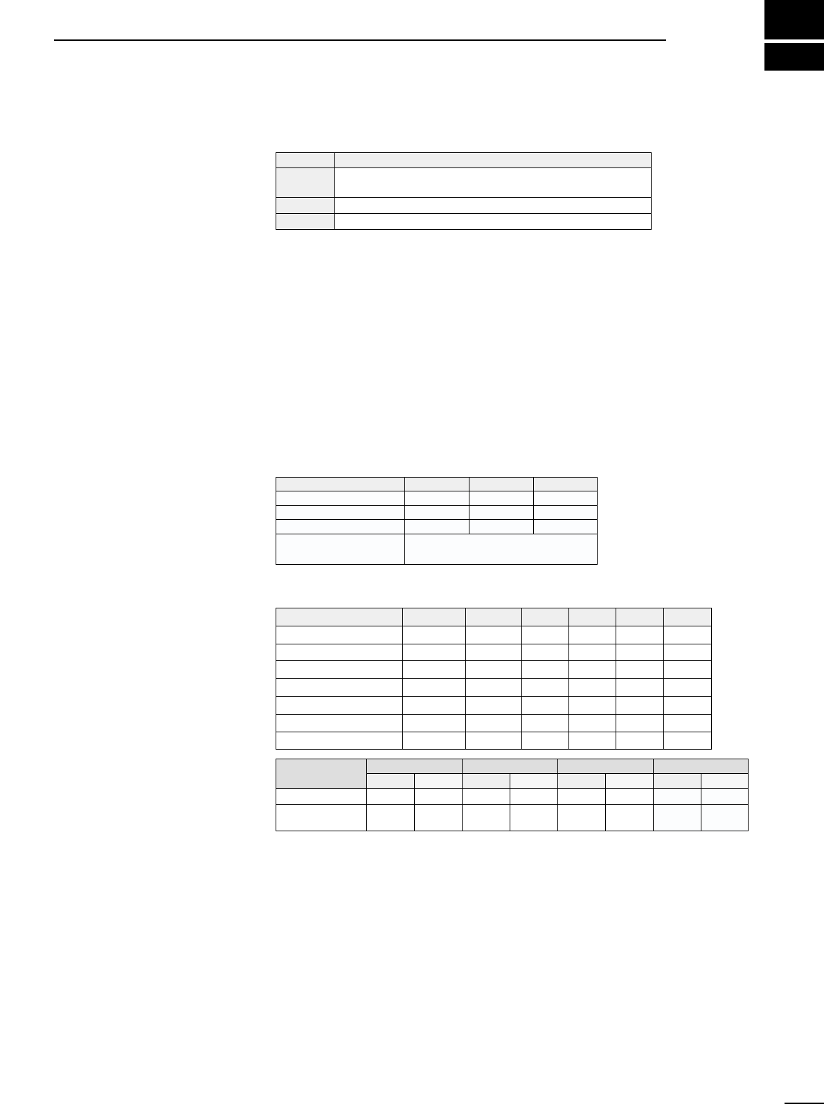
10 CONTROL COMMANDS ............................ 35–36
■ Command table ......................................................... 35
■ Data format ................................................................35
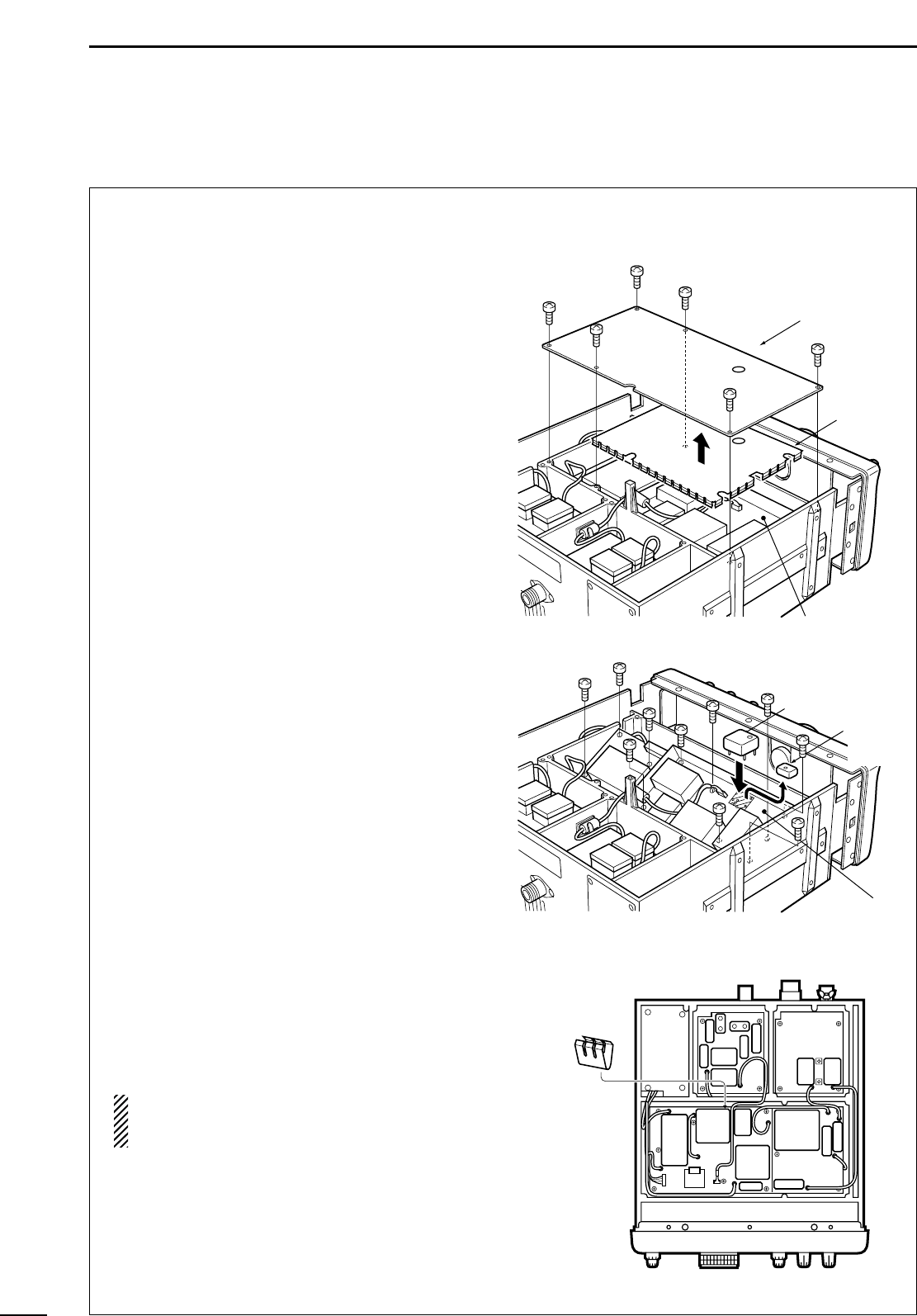
11 MAINTENANCE ................................................. 37
■ Disassembly .............................................................. 37
■ Fuse replacement ......................................................37
■ Level adjustments ...................................................... 37
■ Memory backup ......................................................... 37
■ CPU resetting ............................................................ 37
■ Cleaning ..................................................................... 37
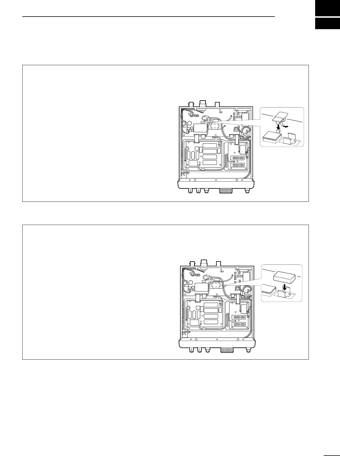
12 OPTIONAL INSTALLATIONS ..................... 38– 39
■ UT-102
VOICE SYNTHESIZER UNIT
................................ 38
■ FL-52A
CW NARROW FILTER
........................................ 38
■ CR-293
HIGH STABILITY CRYSTAL UNIT
......................... 39
13 TROUBLESHOOTING ................................. 40–41
14 SPECIFICATIONS .............................................42
15 OPTIONS ........................................................... 43
16 DOC ...................................................................44
ii