iv
SAFETY TRAINING INFORMATION ............................................... i
FOREWORD ................................................................................... ii
IMPORTANT .................................................................................... ii
EXPLICIT DEFINITIONS ................................................................. ii
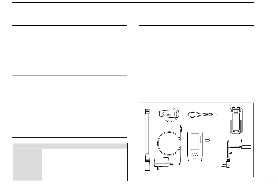
SUPPLIED ACCESSORIES ............................................................ ii
PRECAUTIONS............................................................................... iii
TABLE OF CONTENTS ................................................................. iv
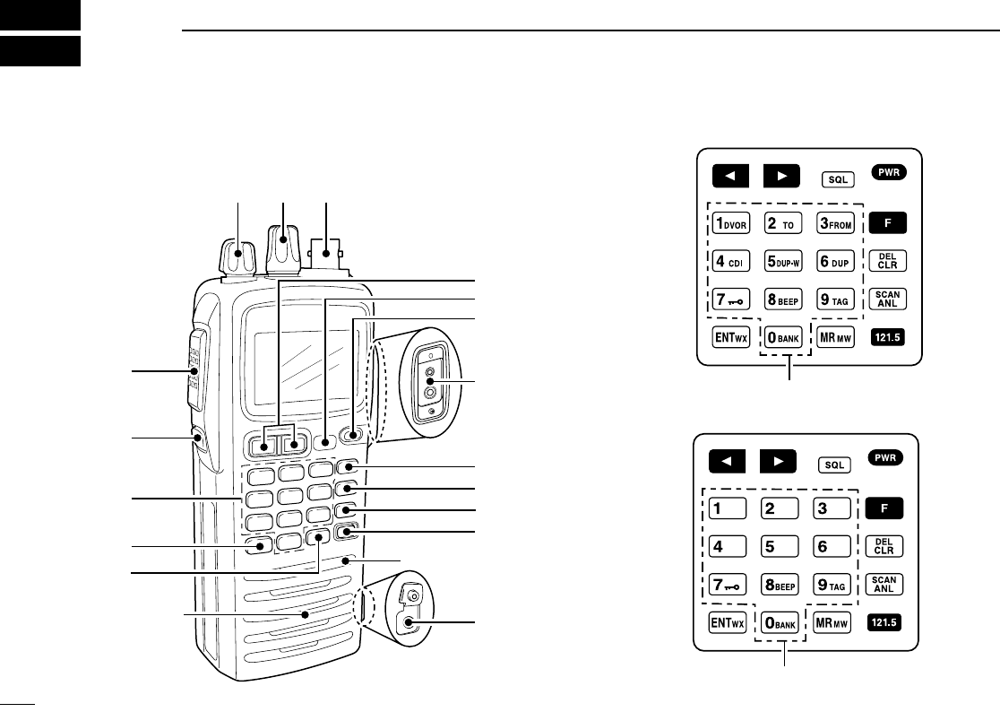
1 PANEL DESCRIPTION ........................................................ 1 – 6
■ Panel description ................................................................... 1
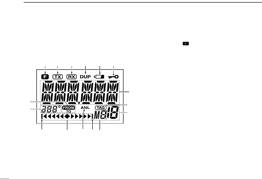
■ Function display ..................................................................... 5
2 ACCESSORY ATTACHMENT .................................................. 7
3 BASIC OPERATION .......................................................... 8 – 11
■ Setting a frequency ................................................................ 8
■ Setting a squelch level ........................................................... 8
■ Selecting a weather channel................................................... 8
■ Receiving ............................................................................... 9
■ Transmitting ........................................................................... 9
■ ANL function ........................................................................... 9
■ Low battery indicator ............................................................ 10
■ Recall function ..................................................................... 10
■ Setting weather alert function................................................ 11
■ Accessing 121.5 MHz emergency frequency ....................... 11
■ Lock function ........................................................................ 11
■ Side tone function ................................................................ 11
■ Setting beep tone ................................................................. 11
■ Backlighting .......................................................................... 11
4 MEMORY OPERATION ................................................... 12 – 15
■ Memory channel selection ................................................... 12
■ Transferring memory contents ............................................. 12
■ Programming a memory channel ......................................... 13
■ Memory names .................................................................... 14
■ Clearing the memory contents ............................................. 14
5 SCAN OPERATION ......................................................... 16 – 17
■ Scan types ........................................................................... 16
■ COM band scan ................................................................... 16
■ Memory scan ....................................................................... 16
■ Weather channel scan
(U.S.A. version only) ............................ 17
■ “TAG” channels ................................................................... 17
6 VOR NAVIGATION (IC-A24 only) .................................... 18– 24
■ VOR indications ................................................................... 18
■ VOR functions ...................................................................... 19
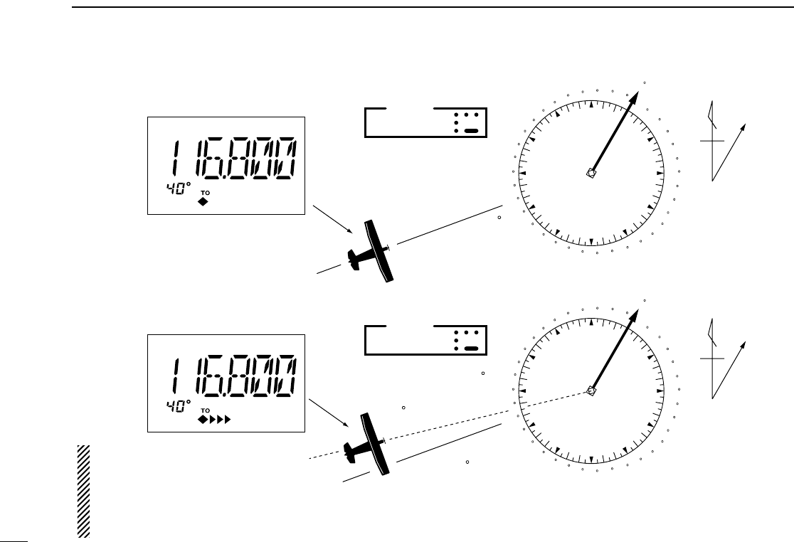
■ Flying to a VOR station ........................................................ 20
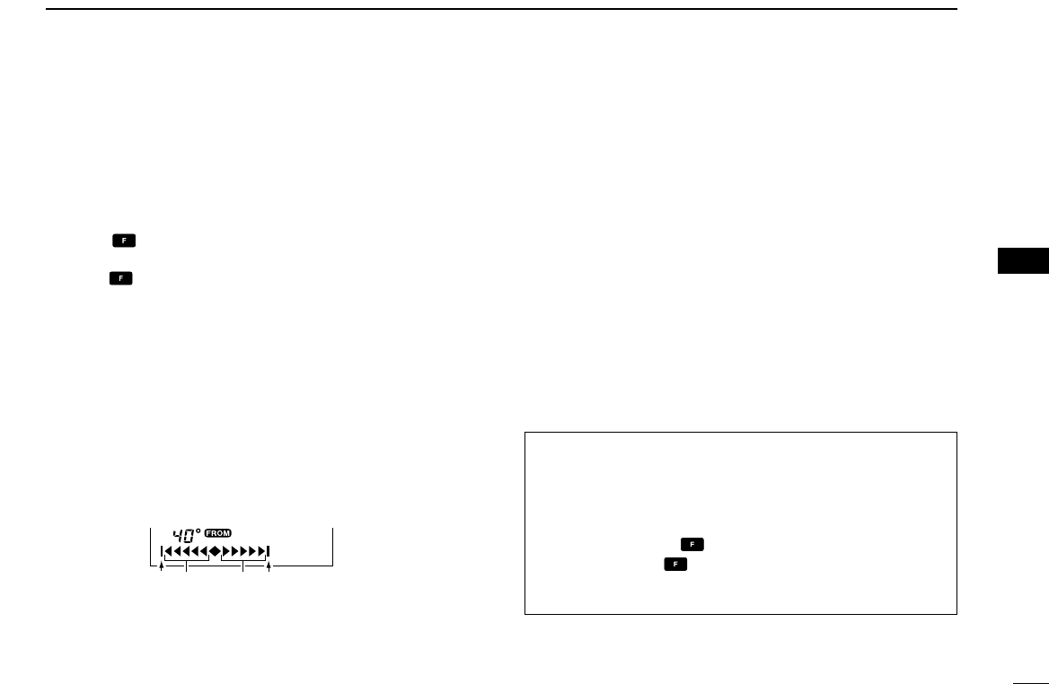
■ Entering a desired course .................................................... 22
■ Crosschecking position ........................................................ 22
■ Duplex operation
(U.S.A. version only) .................................... 24
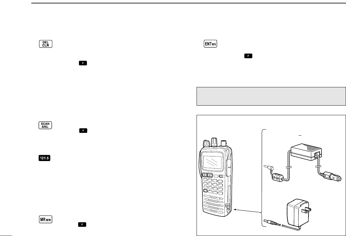
7 BATTERY PACKS ........................................................... 25 –27
■ Battery charging ................................................................... 25
■ Battery cautions ................................................................... 25
■ Optional battery case ........................................................... 26
■ Optional battery chargers ..................................................... 27
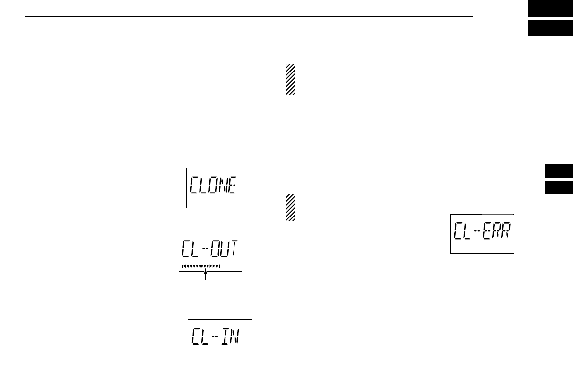
8 CLONING ................................................................................ 28
9 TROUBLESHOOTING ............................................................ 29
10 SPECIFICATIONS .................................................................. 30
11 OPTIONS ................................................................................ 31
12 QUICK REFERENCE ...................................................... 32 – 33
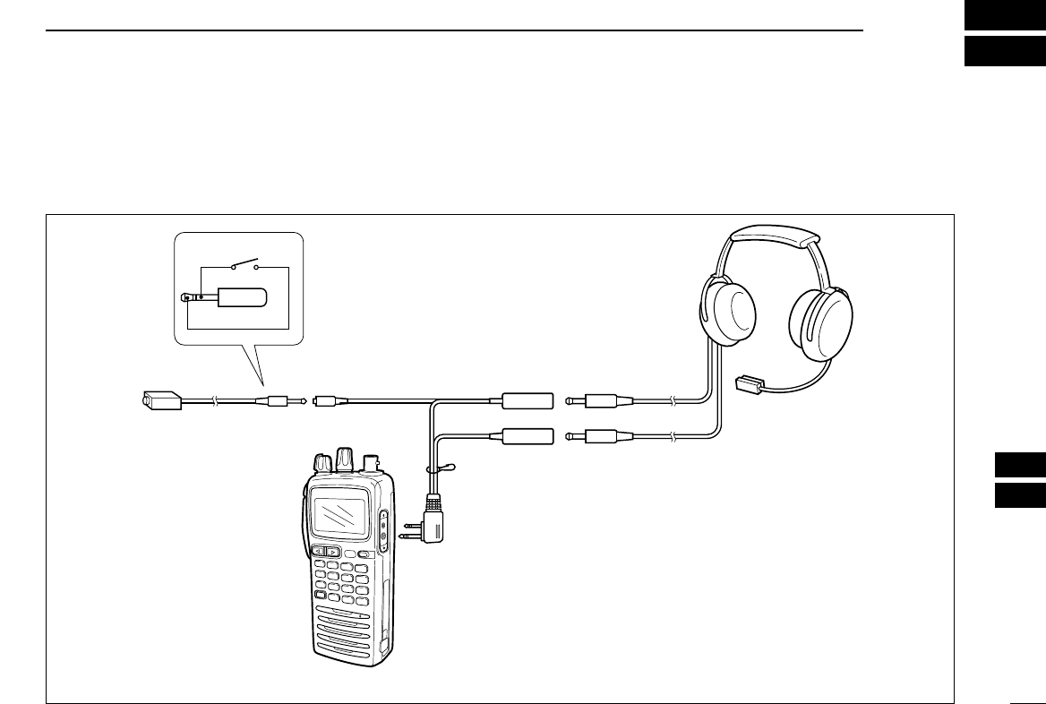
13 OPTIONAL HEADSET CONNECTION .................................. 34
TABLE OF CONTENTS