704.2007 TR10A041-C RE
Dear Customer,
Thank you for choosing this quality product from our company.
Please keep these instructions in a safe place for later reference.
Please observe the following instructions. They provide you with
important information on the safe installation, operation and
correct care/maintenance of your garage door operator, thus
ensuring that this product will give you satisfaction for many
years to come.
Please observe all our safety notes and warnings, specifically
headed ATTENTION, CAUTION or Note.
ATTENTION
Installation, maintenance, repair and dismantling
of the garage door operator may only be carried
out by specialists.
Note
The inspection log book and instructions for safe handling
and maintenance of the door must be placed at the dis-
posal of the end user.
1 IMPORTANT NOTES
ATTENTION
Incorrect installation or handling of the operator
could result in serious injury. Therefore, please
follow these instructions fully and with due care.
1.1 Important safety instructions
The garage door operator is designed and intended
exclusively for the impulse operation of spring-balanced
up-and-over and sectional doors in the domestic /
non-commercial sector as well as for garage doors
subjected to greater wear (e.g. underground and collec-
tive garages). Use in the commercial sector is not
permitted.
Please observe the manufacturer’s specifications regar-
ding the door and operator combination. Possible hazards
as defined in EN 12604 and EN 12453 are prevented
by the design itself and by carrying out installation in
accordance with our guidelines. Door systems used by
the general public and equipped with a single protective
device only, e.g. force limit, may only be used when
monitored.
1.1.1 Warranty
We shall be exempt from our warranty obligations and
product liability in the event that the customer carries out
his own structural alterations or undertakes improper
installation work or arranges for same to be carried out
by others without our prior approval and contrary to the
installation guidelines we have provided. Moreover, we
shall accept no responsibility for the inadvertent or negli-
gent operation of the operator and accessories nor for
the improper maintenance of the door and/or its counter-
balance mechanism. Batteries and light bulbs are also
not covered by the warranty.
Note
Should the garage operator fail, a specialist must be
immediately entrusted with its inspection / repair.
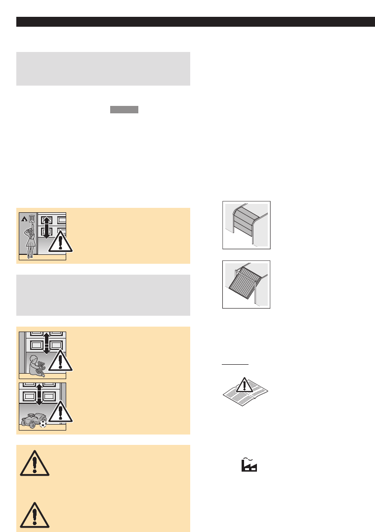
1.1.2 Checking the door / door system
The design of the operator is not suitable nor intended
for the opening and closing of heavy doors, i.e. doors
that can no longer be opened or closed manually or
only do so with extreme difficulty. Before installing
the operator, it is therefore necessary to check
the door and make sure that it can also be easily
moved by hand.
To do this, raise the door approx. 1 metre and then let it
go. The door should retain this position, moving neither
up nor down. If the door, moves in any of the two direc-
tions, there is a risk that the compensating springs are
defective or incorrectly adjusted. In this case, increased
wear and malfunctioning of the door system is to be
expected.
CAUTION: Danger to life!
Never attempt to change, readjust, repair or
move the compensating springs for the door’s
counterbalance mechanism or their holders.
The springs are under considerable tension
and can cause serious injury.
Furthermore, check the entire door system
(pivots, door bearings, cables, springs and
fastenings) for wear and possible damage.
Check for signs of corrosion and fractures.
The door system may not be used if repair or
adjustment work needs to be carried out. Al-
ways remember that a fault in the door system
or a misaligned door can also cause severe
injury.
Note
Before installing the operator and in the interests of personal
safety, make sure that any work on the door’s compensa-
ting springs, and if necessary, any maintenance and repair
work, is carried out by a specialist.
Only correct fitting and maintenance in compliance with
the instructions by a competent/specialist company or a
competent/qualified person ensures safe and flawless
operation of the system.
1.2 Important instructions for a safe installation
The specialist carrying out the work must ensure that in-
stallation is conducted in compliance with the prevailing
national regulations on occupational safety and those
governing the operation of electrical equipment.
Possible hazards as defined in DIN EN 13241-1 are pre-
vented by the design itself and by carrying out installa-
tion in accordance with our guidelines.
1.2.1 Before installing the garage door operator check
that the door is in a flawless mechanical condition and
is correctly balanced, so that it can be easily moved
by hand (EN 12604). Further check whether the door
opens and closes properly (see section 1.1.2).
In addition, any of the door’s mechanical locks and
latches not needed for power operation of the garage
door should be immobilized. This includes in particular
any locking mechanism connected with the door lock
(see sections 2.3 and 2.6).
The garage door operator is designed for use in dry
buildings and therefore must not be installed outdoors.
The garage ceiling must be constructed in such a way
as to guarantee safe, secure anchoring of the operator.
In the case of ceilings that are too high or too lightweight,
the operator must be attached to additional braces.
ENGLISH