502639
13
Zoom out
Zoom in
Previous page
1/60
Next page
AVR 8000 Audio/VideoReceiver
OWNER’S MANUAL
®
Power for the Digital Revolution.
®
2 TABLE OF CONTENTS
3 Introduction
4 Safety Information
4 Unpacking
5 Front Panel Controls
7 Front Panel Information Display
8 Rear Panel Connections
10 Main Remote Control Functions
14 Zone II Remote Control Functions
15 Installation and Connections
18 System Configuration
18 Speaker Placement
19 System Setup
20 Input Setup
21 Speaker Setup
22 Surround Setup
24 Delay Settings
24 Output Level Adjustment
25 Using EzSet
25 Manual Output Level Adjustment
26 Bass Peak Limiter
28 Operation
28 Surround Mode Chart
30 Basic Operation
30 Source Selection
30 Volume Control
30 Surround Mode Selection
31 Digital Audio Playback
33 Tuner Operation
34 Tape Recording
34 Front Panel Connections
34 Output Level Trim Adjustment
35 6-Channel/8-Channel Direct Input
36 Advanced Features
36 Display Brightness
36 Turn-On Volume Level
36 Semi-OSD Settings
38 Multiroom Operation
39 Programming the Remote
39 Direct Code Entry
39 Auto Search Method
39 Code Readout
40 Learning Codes
40 Macro Programming
41 Programmed Device Functions
42 Volume Punch-Through
42 Channel Control Punch-Through
42 Transport Control Punch-Through
43 Reassigning Device Control
Selectors
43 Resetting the Remote Memory
44 Function List
46 Setup Code Tables
56 Troubleshooting Guide
56 Processor Reset
57 Technical Specifications
AVR 8000 Audio/VideoReceiver
Typographical Conventions
In order to help you use this manual with the remote control, front panel controls and rear panel
connections, certain conventions have been used.
EXAMPLE – (bold type) indicates a specific remote control or front panel button, or rear panel
connection jack
EXAMPLE (OCR type) indicates a message that is visible on-screen or on the front panel
information display
1 (number in a square) indicates a specific front panel control
¡ (number in a circle) indicates a rear panel connection
a (number in an oval) indicates a button or indicator on the remote
A (letter in a square) indicates an indicator in the front panel display
å
(letter in an oval) indicates a button on the Zone II remote
3 INTRODUCTION
Introduction
Thank you for choosing Harman Kardon!
With the purchase of a Harman Kardon
AVR 8000 you are about to begin many years
of listening enjoyment. Designed to provide all
the excitement and detail of movie soundtracks
and
every nuance of musical selections, the
AVR 8000
is truly a multichannel receiver for
the new millennium.
The AVR 8000 has been engineered so that it
is easy to take advantage of all the power of
its digital technology. On-screen menus, fully
color-coded connection jacks and terminals
and our exclusive EzSet remote make installa-
tion fast and simple. However, to obtain the
maximum enjoyment from your new receiver,
we urge you to read this manual. A few min-
utes spent learning the functions of the various
controls will enable you to take advantage of
all the power the AVR 8000 is able to deliver.
If you have any questions about this product,
its installation or its operation, please contact
your retailer or custom installer. They are your
best local sources of information.
Description and Features
The AVR 8000 is among the most versatile and
multifeatured A/V receivers available, incorpo-
rating a wide range of listening options. In
addition to the benefits of world-famous
THX Ultra processing, as well as Dolby Digital
and DTS decoding for digital sources, a broad
choice of Matrix surround-encoded or Stereo
surround modes are available for use with
sources such as CD, VCR, TV broadcasts and the
AVR 8000s own FM/AM tuner. Along with THX
Surround EX, Dolby Pro Logic II, DTS Neo:6,
Dolby 3 Stereo, and Hall and Theater modes,
the AVR 8000 offers Harman Internationals
exclusive Logic 7 process in both 5.1 and 7.1
versions to create a wider, more enveloping
field environment and more defined fly-overs
and pans. Another Harman Kardon exclusive is
VMAx, which uses proprietary processing to
create an open, spacious sound field even
when only two front speakers are available.
Finally, the AVR 8000 is among the very few
A/V receivers that offer decoding of MP3 data,
so that you may listen to the latest music selec-
tions directly from compatible computers or
playback devices with the power and fidelity
you expect from Harman Kardon.
In addition to providing a wide range of listen-
ing options, the AVR 8000 is easy to configure
so that it provides the best results with your
speakers and specific listening-room environ-
ment. On-screen menus make it simple to enter
settings for speaker configurations and bass
management, and the EzSet remote measures
a systems sound levels and automatically
calibrates them for perfectly balanced sound
field presentation.
For the ultimate in flexibility, the AVR 8000 fea-
tures connections for six video devices, all with
both composite and S-Video inputs. Two addi-
tional audio inputs are available, and a total of
eight digital inputs make the AVR 8000 capable
of handling all the latest digital audio sources.
For compatibility with the latest HDTV video
sources and progressive scan DVD players, the
AVR 8000 also features wide-bandwidth, low-
crosstalk component video switching.
Behind a front panel door are coax and optical
digital inputs and outputs for direct connection
to digital recorders, along with analog
audio/video connections that may be switched
to outputs for use with portable recorders a
Harman Kardon exclusive. Two video recording
outputs, preamp-out and main amp-in jacks,
and a color-coded eight-channel input make
the AVR 8000 virtually future-proof, with
everything needed to accommodate tomorrows
new formats right on board.
The AVR 8000s flexibility and power extend
beyond your main home theater or listening
room. The AVR 8000 includes a sophisticated
multizone control system that allows you to
select one source for use in the main room
and a different source for audio and video
distribution to a second zone. Complete volume
control in the second zone is possible with a
separate infrared control link. To make it easy
to operate the AVR 8000 from a remote zone,
a separate Zone IIremote is included.
The AVR 8000s powerful amplifier uses
traditional Harman Kardon high-current design
technologies to meet the wide dynamic range
of any program selection.
Harman Kardon invented the high-fidelity
receiver more than forty-seven years ago.
With
state-of-the-art circuitry and time-honored
circuit designs, the AVR 8000 is the perfect
combina
tion of the latest in digital audio
technology, a
quiet yet powerful analog
amplifier in an
elegant, easy-to-use package.
THX
®
Ultra processing, THX Surround EX,
Dolby* Digital and Dolby Pro Logic* II
decoding, and the full suite of DTS
®
modes, including DTS-ES
®
6.1 Discrete
& Matrix and Neo:6
®
using the latest
24-bit, twin-core Crystal
®
DSP engine
Harman Kardons exclusive Logic 7
®
processing, available for the first time
with both 7.1 and 5.1 processing in
a variety of modes and two modes
of VMAx
®
MP3 decoding for use with computers
and digital audio players
remote automatically sets
output levels for optimum performance
High-bandwidth, HDTV-compatible
component video switching
Discrete front panel coaxial and opti-
cal digital inputs and outputs for easy
connection to portable digital devices
and the latest video game consoles
Multiple digital inputs and outputs
Front panel analog A/V jacks switch-
able to outputs for easy connection to
portable digital devices and video
game consoles
On-screen menu and display system
Complete multizone system allows a
separate audio and video source to
be sent to a remote zone separate
Zone II remote included
TM
CAUTION
RISK OF ELECTRIC SHOCK
DO NOT OPEN
CAUTION: To prevent electric shock,
do not use this (polarized)
plug with an extension cord,
receptacle or other outlet
unless the blades can
be fully inserted to
prevent blade exposure.
The lightning flash with arrowhead symbol,
within an equilateral triangle, is intended to
alert the user to the presence of uninsulated
dangerous voltage within the products
enclosure that may be of sufficient magnitude to constitute a
risk of electric shock to persons.
The exclamation point within an equilateral
triangle is intended to alert the user to the
presence of important operating and
maintenance (servicing) instructions in the
literature accompanying the appliance.
4 SAFETY INFORMATION
Safety Information
Important Safety Information
Verify Line Voltage Before Use
Your AVR 8000 has been designed for use with
120-volt AC current. Connection to a line volt-
age other than that for which it is intended
can create a safety and fire hazard and may
damage the unit.
If you have any questions about the voltage
requirements for your specific model, or about
the line voltage in your area, contact your selling
dealer before plugging the unit into a wall outlet.
Do Not Use Extension Cords
To avoid safety hazards, use only the power
cord attached to your unit. We do not recom-
mend that extension cords be used with this
product. As with all electrical devices, do not
run power cords under rugs or carpets or place
heavy objects on them. Damaged power cords
should be replaced immediately by an author-
ized service depot with a cord meeting factory
specifications.
Handle the AC Power Cord Gently
When disconnecting the power cord from an
AC outlet, always pull the plug; never pull the
cord. If you do not intend to use the unit for
any considerable length of time, disconnect the
plug from the AC outlet.
Do Not Open the Cabinet
There are no user-serviceable components
inside this product. Opening the cabinet may
present a shock hazard, and any modification
to the product will void your guarantee. If water
or any metal object such as a paper clip, wire
or a staple accidentally falls inside the unit, dis-
connect it from the AC power source immedi-
ately, and consult an authorized service station.
CATV or Antenna Grounding
If an outside antenna or cable system is con-
nected to this product, be certain that it is
grounded so as to provide some protection
against voltage surges and static charges.
Section 810 of the National Electrical Code,
ANSI/NFPA No. 70-1984, provides information
with respect to proper grounding of the mast
and supporting structure, grounding of the lead-
in wire to an antenna discharge unit, size of
grounding conductors, location of antenna dis-
charge unit, connection to grounding electrodes
and requirements of the grounding electrode.
NOTE TO CATV SYSTEM INSTALLER: This
reminder is provided to call the CATV (Cable
TV) system installers attention to article 820-
40 of the NEC that provides guidelines for
proper grounding and, in particular, specifies
that the cable ground shall be connected to the
grounding system of the building, as close to
the point of cable entry as possible.
Installation Location
To ensure proper operation and to avoid the
potential for safety hazards, place the unit
on a firm and level surface. When placing the
unit on a shelf, be certain that the shelf and
any mounting hardware can support the
weight of the product.
Make certain that proper space is provided
both above and below the unit for ventila-
tion. If this product will be installed in a
cabinet or other enclosed area, make certain
that there is sufficient air movement within
the cabinet. Under some circumstances a fan
may be required.
Do not place the unit directly on a carpeted
surface.
Avoid installation in extremely hot or cold
locations, or in an area that is exposed to
direct sunlight or heating equipment.
Avoid moist or humid locations.
Do not obstruct the ventilation slots on the
top of the unit, or place objects directly
over them.
Cleaning
When the unit gets dirty, wipe it with a clean,
soft, dry cloth. If necessary, wipe it with a soft
cloth dampened with mild soapy water, then a
fresh cloth with clean water.Wipe dry immedi-
ately with a dry cloth. NEVER use benzene,
aerosol cleaners, thinner, alcohol or any other
volatile cleaning agent. Do not use abrasive
cleaners, as they may damage the finish of metal
parts. Avoid spraying insecticide near the unit.
Moving the Unit
Before moving the unit, be certain to discon-
nect any interconnection cords with other com-
ponents, and make certain that you disconnect
the unit from the AC outlet.
Important Information for the User
This equipment has been tested and found to
comply with the limits for a Class-B digital
device, pursuant to Part 15 of the FCC Rules.
The limits are designed to provide reasonable
protection against harmful interference in a
residential installation. This equipment gener-
ates,
uses and can radiate radio-frequency energy
and, if not installed and used in accordance
with the instructions, may cause harmful inter-
ference to radio communication. However, there
is no guarantee that harmful interference will
not occur in a particular installation. If this
equipment does cause harmful interference to
radio or television reception, which can be
determined by turning the equipment off and
on, the user is encouraged to try to correct the
interference by one or more of the following
measures:
Reorient or relocate the receiving antenna.
Increase the separation between the equip-
ment and receiver.
Connect the equipment into an outlet on a
circuit different from that to which the
receiver is connected.
Consult the dealer or an experienced
radio/TV technician for help.
This device complies with Part 15 of the FCC
Rules. Operation is subject to the following two
conditions: (1) this device may not cause harm-
ful interference, and (2) this device must accept
interference received, including interference
that may cause undesired operation.
NOTE: Changes or modifications may cause
this unit to fail to comply with Part 15 of the
FCC Rules and may void the users authority to
operate the equipment.
Unpacking
The carton and shipping materials used to pro-
tect your new receiver during shipment were
specially designed to cushion it from shock and
vibration. We suggest that you save the carton
and packing materials for use in shipping if you
move, or should the unit ever need repair.
To minimize the size of the carton in storage,
you may wish to flatten it. This is done by care-
fully slitting the tape seams on the bottom and
collapsing the carton. Other cardboard inserts
may be stored in the same manner. Packing
materials that cannot be collapsed should be
saved along with the carton in a plastic bag.
If you do not wish to save the packaging mate-
rials, please note that the carton and other sec-
tions of the shipping protection are recyclable.
Please respect the environment and discard
those materials at a local recycling center.
At this time you should remove the protective
plastic film from the front panel lens. Leaving
the film in place may affect the performance of
your remote control.
5 FRONT PANEL CONTROLS
1 Main Power Switch: Press this button
to apply power to the AVR 8000. When the
switch is pressed in, the unit is placed in a
Standby mode, as indicated by the amber
Power Indicator 3 surrounding the
System Power Control 2. This button
MUST be pressed in to operate the unit. To
turn the unit off and prevent the use of the
remote control, this switch should be pressed
until it pops out from the front panel so that
the word OFFmay be read at the top of
the switch.
NOTE: This switch is normally left in the ON
position.
2 System Power Control: When the Main
Power Switch
1
is ON,press this button to
turn on the AVR 8000; press it again to turn the
unit off. Note that the
Power Indicator
3
surrounding the switch will turn green when
the unit is on.
3 Power Indicator: This LED will be lit in
amber when the unit is in the Standby mode to
signal that the unit is ready to be turned on.
When the unit is in operation, the indicator will
turn green.
4 Headphone Jack: This jack may be used to
listen to the AVR 8000s output through a pair
of headphones. Be certain that the headphones
have a standard
1
/4" stereo phone plug. Note
that the main room speakers will automatically
be turned off when the headphone jack is
in use.
5 Dolby Mode Selector: Pressing this
selector button cycles the AVR through the
various Dolby surround modes. The first press
of the button switches the surround mode to
the last Dolby surround mode that was in use.
The choice of modes available will vary based on
the type of input source (digital or analog) and
the number of speaker channels your system is
configured for.
6 Home THX Mode Selector: Press this
button to select Home THX processing. The
choice of THX modes will vary according to
the type of input source and program material
(Dolby Digital, DTS 5.1, DTS 6.1 or analog), and
the number of speakers in your system. In some
cases the system will auto-default to the THX
Surround EX or THX Cinema mode, while in
other cases you will have a choice of modes.
7 Logic 7 Mode Selector/
Button: This
button has two functions: In normal use, press
it to select one of the Logic 7 modes. When an
adjustment is being made using using the
Front Panel Controls
1 Main Power Switch
2 System Power Control
3 Power Indicator
4 Headphone Jack
5 Dolby Mode Selector
6 Home THX Mode Selector
7 Logic 7 Mode Selector/
Button
8 Tone Mode
9 DSP Surround Mode Selector
) Tuning Selector
! Tuner Band Selector
@ 6Ch/8Ch Direct Button
# Preset Station Selector
$ Stereo Mode Selector/
Button
% Input Source Selector
^ FM Mode Selector
& Optical Digital 4 Input Jack
* Optical Digital 4 Output Jack
( Coaxial Digital 4 Input Jack
Ó Coaxial Digital 4 Output Jack
Ô Input/Output Status Indicator
Video 5 Input Jacks
Ò DTS Neo:6 Mode Selector
Ú Digital Select Button
Û DTS Surround Mode Selector
Ù Volume Control
ı Input Indicators
ˆ Main Information Display
˜ Remote Sensor Window
¯ Surround Mode/Bitstream Indicators
2
4
7
9
@
Ú
ı
¯
Û
Ù
1
3
5
6
8
)
!
#
$
%
^
&
Ó
*
(
Ô
Ò
ˆ
˜
6 FRONT PANEL CONTROLS
Front Panel Controls
Digital Select Button Ú, this button may be
pressed to scroll through the available options.
8 Tone Mode: This button controls the tone
control settings, enabling adjustment of the bass
and treble boost/cut or the removal of the tone
controls from the signal path. The first press of
the button displays a
TONE IN message in
the
Main Information Display ˆ. If you
wish to take the tone controls to flat, without
any treble or bass alteration, press the
or
Selector Buttons 7$ so that TONE
OUT
appears in the Lower Display Line B.
To change the tone settings, press the button
until either
TREBLE or BASS appears in
the
Lower Display Line B as desired, and
then press the
or
Selector Buttons
7$ to increase or decrease the setting. Note
that the Tone settings apply only to the front
left and right speakers, and they are not in
effect when a THX mode is in use.
9 DSP Surround Mode Selector: Press this
button to select the following DSP Surround
Modes: Hall 1, Hall 2 or Theater. (See page 28
for more information about surround modes.)
) Tuning Selector: Press the left side of the
button to tune lower-frequency stations and the
right side of the button to tune higher-frequency
stations. When a station with a strong signal
is reached, the
TUNED Indicator I will be lit
in the
Main Information Display ˆ.
To tune manually, tap the button lightly and
note that the tuner will step up one frequency
increment per button press. When the button is
held for a few seconds you will note that the
unit will quickly search the frequency band.
Release it once the fast tuning starts; the tuner
will automatically scan for the next station with
an acceptable signal and then stop.
! Tuner Band Selector: Pressing this but-
ton will automatically switch the AVR 8000 to
the Tuner mode. Pressing it again will switch
between the AM and FM frequency bands. (See
page 33 for more information on the tuner.)
@ 6Ch/8Ch Direct Button: Press this button
to select the 6-Channel Direct or 8-Channel
Direct inputs as the AVR 8000s source.
# Preset Station Selector: Press this
button to scroll up or down through the list or
stations that have been entered into the preset
memory. (See pages 33 and 34 for more infor-
mation on tuner programming.)
$ Stereo Mode Selector/
Button:
Pressing this selector button cycles through the
stereo modes, and it is also used to turn off all
surround processing and place the unit in a tra-
ditional two-channel Stereo mode. The first
press selects 5-Channel Stereo, the next press
selects 7-Channel Stereo, and the third press
selects SURROUND OFF, which is true Stereo.
% Input Source Selector: Press this button
to change the input by scrolling up or down
through the list of input sources.
^ FM Mode Selector: Press this button to
select Auto or Manual tuning. When the button
is pressed so that the
AUTO Indicator J
lights, the tuner will search for the next station
with an acceptable signal when the
Tuning
Selector
)u
é
is pressed. When the but-
ton is pressed so that the
AUTO Indicator J
is not lit, each press of the Tuning Selector
)u
é
will increase the frequency. (See
page 33 for more information on using the
tuner.)
NOTE: The front panel digital audio, video and
analog audio input and output jacks are nor-
mally concealed behind a drop-down door in the
lower right corner of the front panel. To access
these jacks, open the panel door by gently
pulling down the upper right corner of the door
as indicated by PULL/OPEN.
& Optical Digital 4 Input Jack: Connect the
optical digital output of an audio or video prod-
uct to this jack.
* Optical Digital 4 Output Jack: Connect
this jack to the optical digital input of a digital
recorder to send a feed of the digital output
when a PCM digital input source is in use by
the AVR 8000.
( Coaxial Digital 4 Input Jack: Connect the
output of a digital audio source to this jack.
Ó Coaxial Digital 4 Output Jack: Connect
this jack to the coaxial digital input of a digital
recorder to send a feed of the digital output
when a PCM digital input source is in use by
the AVR 8000.
Ô Input/Output Status Indicator: This LED
indicator will normally light green to show that
the front panel
Video 5 Input Jacks are
operating as inputs. When these jacks are
configured for use as an output, the indicator
will turn red to show that the jack may be used
for recording. (See page 34 for more information
on configuring the front panel jacks as outputs,
rather than inputs.)
Video 5 Input Jacks: These audio/video
jacks may be used for temporary connection to
video games or portable audio/video products
such as camcorders and portable audio players.
Ò DTS Neo:6 Mode Selector: Pressing this
button selects one of the DTS Neo:6 modes. The
first press selects the Neo:6 Movies mode, and
a second press will select the Neo:6 Music
mode. (See page 28 for more information on
the Neo:6 modes.)
Ú Digital Select Button: When playing a
source that has a digital output, press this
button to select between the
Optical &e
and Coaxial (b Digital inputs. (See page
31 for more information on digital audio.)
Û DTS Surround Mode Selector: Pressing
this selector button cycles the AVR through the
DTS surround modes. The choice of available
DTS modes will vary according to the type of
program source material (DTS 5.1 or DTS 6.1)
and whether your system is configured for 5.1
or 6.1/7.1 channel operation.
Ù Volume Control: Turn this knob clockwise
to increase the volume, counterclockwise to
decrease the volume. If the AVR 8000 is muted,
adjusting volume control will automatically
release the unit from the silenced condition.
ı Input Indicators: A green LED will light
to the left of the input that is currently the
input source for the AVR 8000.
ˆ Main Information Display: This display
delivers messages and status indications to
help you operate the receiver. (See page 7
for a complete explanation of the Information
Display.)
˜ Remote Sensor Window: The sensor
behind this window receives infrared signals
from the remote control. Aim the remote at this
area and do not block or cover it unless an
external remote sensor is installed.
¯ Surround Mode/Bitstream Indicators:
These LEDS will light to show the surround
mode and digital bitstream in use. Note that
depending on the specific combination of input
sources and surround mode selected, more
than one indicator may light. (See page 32 for
more information.)
7 FRONT PANEL INFORMATION DISPLAY
Front Panel Information Display
A
B
D
E
K
L
F
H
I
J
C
G
A Upper Display Line
B Lower Display Line
C OSD Indicator
D Multiroom Indicator
E Speaker/Channel Input Indicators
F PRESET Indicator
G MEMORY Indicator
H STEREO Indicator
I TUNED Indicator
J AUTO Indicator
K 192kHz Indicator
L 96kHz Indicator
A Upper Display Line: Depending on the units
status, a variety of messages will appear here. In
normal operation, the current input source name
will appear on this line.
B Lower Display Line: Depending on the
units status, a variety of messages will appear
here. In normal operation, the current surround
mode name will appear on this line.
C OSD Indicator: When the OSD system is in
use, this indicator lights to remind you that the
other indicators in this display do not function
when the On-Screen Display is being used.
D Multiroom Indicator: This indicator lights
when the multiroom system is active. Note that
it will remain lit when the multiroom system is
in use even though the main room system is in
the Standby mode and all other indicators are
dark. (See page 38 for more information on the
Multiroom system.)
E Speaker/Channel Input Indicators: These
indicators are multipurpose, indicating either the
speaker type selected for each channel or the
incoming data-signal configuration.The left,
center, right, right surround and left surround
speaker indicators are composed of three boxes,
while the subwoofer is a single box. The center
box lights when a Smallspeaker is selected,
and the two outer boxes light when Large
speakers are selected. When none of the boxes
are lit for the center, surround or subwoofer
channels, no speaker has been selected for one
of those positions. (See page 21 for more infor-
mation on configuring speakers.) The letters
inside each of the center boxes display the active
input channels. For standard analog inputs, only
the L and R will light, indicating a stereo input.
When a digital source is playing, the indicators
will light to display the channels being received
at the digital input. When the letters flash, the
digital input has been interrupted. (See pages
25 & 32 for more information on the Channel
Indicators.)
F PRESET Indicator: This indicator lights
when the tuner is in use to show that the
present number for the current station being
listened to appears in the Upper Display Line.
(See page 34 for more information on tuner
presets.)
G MEMORY Indicator: This indicator flashes
when entering presets and other information
into the tuners memory.
H STEREO Indicator: This indicator lights
when an FM station is being tuned in stereo.
I
TUNED Indicator:
This indicator lights when
a station is being received with sufficient signal
strength to provide acceptable listening quality.
J AUTO Indicator: This indicator lights when
the tuners Auto mode is in use.
K 192kHz Indicator: This indicator lights
when the input source has a 192kHz bit rate.
L 96kHz Indicator: This indicator lights
when the input source has a 96kHz bit rate.
8 REAR PANEL CONNECTIONS
¡ AM Antenna: Connect the AM loop antenna
supplied with the receiver to these terminals. If an
external AM antenna is used, make connections
to the
AM and GND terminals in accordance
with the instructions supplied with the antenna.
FM Antenna: Connect the supplied indoor or
an optional external FM antenna to this terminal.
£ Tape Outputs: Connect these jacks to the
RECORD/INPUT jacks of an audio recorder.
¢ Front Speaker Outputs: Connect these
outputs to the matching + or terminals on
your left and right speakers. When making
speaker connections always make certain to
maintain correct polarity by connecting the
color-coded (white for front left and red for
front right) (+) terminals on the AVR 8000 to
the red (+) terminals on the speakers and the
black () terminals on the AVR 8000 to the
black () terminals on the speakers. See page
15 for more information on speaker polarity.
Surround Speaker Outputs: Connect
these outputs to the matching + and termi-
nals on your surround channel speakers. In con-
formance with the new CEA color code specifi-
cation, the Blue terminal is the positive, or +
terminal that should be connected to the red
(+) terminal on the Surround Left speaker with
older color coding, while the Gray terminal
should be connected to the red (+) terminal on
the Surround Right speaker with the older color
coding. Connect the black () terminal on the
AVR to the matching black negative () termi-
nals for each surround speaker. (See page 15
for more information on speaker polarity.)
§ Subwoofer Output: Connect this jack to
the line-level input of a powered subwoofer. If
an external subwoofer amplifier is used, con-
nect this jack to the subwoofer amplifier input.
Amplifier Inputs: When the jumper pins
that link the
Preamp Outputs with these
inputs are removed, these jacks may be used to
connect an external source or the AVR 8000s
multiroom system to the internal amplifiers.
Main Channel Preamp Outputs: When
the jumper pins that link the
Amplifier Inputs
with these outputs are removed, these jacks
may be connected to an external power amplifier.
ª CD Inputs: Connect these jacks to the out-
put of a compact disc player or CD changer.
Rear Panel Connections
ª
a
c °
·
b
d
e
f
gi
j
§
31
32
h
k
34
¤
¡
£
¢
¢
33
¡ AM Antenna
FM Antenna
£ Tape Outputs
¢ Front Speaker Outputs
Surround Speaker Outputs
§ Subwoofer Output
Amplifier Inputs
Main Channel Preamp Outputs
ª CD Inputs
Surround Back Preamp Outputs
Tape Inputs
¤ Component Video Outputs
Video 1/Video 2 Component Video Inputs
DVD Component Video Inputs
AC Power Cord Jack
Unswitched AC Accessory Outlet
Switched AC Accessory Outlets
° Center Speaker Outputs
· 8-Channel Direct Inputs
a Coaxial Digital Audio Output
b Coaxial Digital Inputs
c 6-Channel Direct Inputs
d Optical Digital Audio Output
e Optical Digital Inputs
f DVD Inputs
g Amplifier Trigger Jack
h Multizone IR Input
i Remote IR Input
j Remote IR Output
k Video 1/Video 2 Inputs
Video 3/Video 4 Inputs
Multizone Outputs
Video 1/Video 2 Outputs
Video Monitor Outputs
34
33
32
31
9 REAR PANEL CONNECTIONS
Rear Panel Connections
Surround Back Preamp Outputs: When
the AVR is used in the 6.1 or 7.1 configuration,
connect these jacks to an optional, external
power amplifier to power the Surround Back
Channels.
Tape Inputs: Connect these jacks to the
PLAY/OUT jacks of an audio recorder.
¤ Component Video Outputs: Connect
these outputs to the component video inputs of
a video projector or monitor. When a source
connected to one of the
Component Video
Inputs
‹› is selected the signal will be sent
to these jacks.
Video 1/Video 2 Component Video
Inputs:
Connect the Y/Pr/Pb component video
outputs of an HDTV Set-top convertor, satellite
receiver, or other video source device with com-
ponent video outputs to these jacks.
DVD Component Video Inputs: Connect
the Y/Pr/Pb component video outputs of a DVD
player to these jacks.
AC Power Cord Jack: Connect the AC
Power cord to this jack when the installation is
complete. To ensure safe operation, use only
the power cord supplied with the unit. If a
replacement is required it must be of same type
and capacity.
Unswitched AC Accessory Outlet: This
outlet may be used to power any AC device.
The power will remain on at this outlet regard-
less of whether the AVR 8000 is on or off.
NOTE: The total power consumption of all
devices connected to the accessory outlets
should not exceed 100 watts.
Switched AC Accessory Outlets: These
outlets may be used to power any device you
wish to have turned on when the AVR 8000 is
turned on with the
System Power Control
Button
2.
° Center Speaker Outputs: Connect these
outputs to the matching + and terminals on
your center channel speaker. In conformance
with the new CEA color code specification, the
Green Terminal is the positive, or +terminal
that should be connected to the red (+) termi-
nal on speakers with the older color coding.
Connect the black () terminal on the AVR to
the black negative () terminal on your speaker.
(See page 15 for more information on speaker
polarity.)
· 8-Channel Direct Inputs: When an
optional, external source with discrete 7.1 ana-
log audio output capability such as a DVD-
Audio or SACD player is use, connect that units
surround back output jacks here.
a Coaxial Digital Audio Output: Connect
this jack to the coaxial digital input of a
CD-R/RW, MiniDisc or other digital recorder.
b Coaxial Digital Inputs: Connect the coax
digital output from a DVD player, HDTV receiver,
the S/P-DIF output of a compatible computer
sound card playing MP3 files or streams, LD player
or CD player to these jacks. The signal may be
either a Dolby Digital signal, DTS signal or a stan-
dard PCM digital source. Do not connect the RF
digital output of an LD player to these jacks.
c 6-Channel Direct Inputs: When an
optional, external source with discrete 5.1
analog audio output capability such as a
DVD-Audio or SACD player is use, connect
that units output jacks here.
NOTE: To assist in making the correct connec-
tions for multichannel input output and speaker
connections, all connection jacks and terminals
have been color coded in conformance with the
latest CEA standards as follows:
Front Left: White
Front Right: Red
Center: Green
Surround Left: Blue
Surround Right: Gray
Surround Back Left: Brown
Surround Back Right: Tan
Subwoofer: Purple
Digital Audio: Orange
Composite Video: Yellow
Component Video Y: Green
Component Video Pr: Red
Component Video Pb:Blue
d Optical Digital Audio Output: Connect
this jack to the optical digital input connector
on a CD-R/RW, MiniDisc or other digital
recorder.
e Optical Digital Inputs: Connect the opti-
cal digital output from a DVD player, HDTV
receiver, the S/P-DIF output of a compatible
computer sound card playing MP3 files or
streams, LD player or CD player to these jacks.
The signal may be either a Dolby Digital signal,
a DTS signal or a standard PCM digital source.
f DVD Inputs: Connect the analog left/right
audio and composite or S-Video output of a DVD
player or other video source to these jacks.
g Amplifier Trigger Jack: Connect this jack
to the compatible input trigger jack on a power
amplifier or other relay controlled device. The
connected product will turn on when the AVR is
turned on.
h Multizone IR Input: Connect the output of
an IR sensor in a remote room to this jack to
operate the AVR 8000s multiroom control system.
i Remote IR Input: If the AVR 8000s
front-panel IR sensor is blocked due to cabinet
doors or other obstructions, an external IR
sensor may be used. Connect the output of
the sensor to this jack.
j Remote IR Output: This connection per-
mits the IR sensor in the receiver to serve other
remote controlled devices. Connect this jack to
the IR INjack on Harman Kardon (or other
compatible) equipment.
k Video 1/Video 2 Inputs: Connect the
left/right audio and composite or S-Video
PLAY/OUT jacks on a VCR or other video source
to these jacks.
Video 3/Video 4 Inputs: Connect the
left/right audio and composite or S-Video out-
puts of a video source such as a VCR, satellite
receiver, hard drive video recorder or other
device to these jacks.
Multizone Outputs: Connect these jacks
to the optional external audio power amplifier
and video distribution system that delivers the
source selected for multizone distribution.
Video 1/Video 2 Outputs: Connect the
left/right audio and composite or S-Video
Record/Input jacks on a VCR or camcorder to
these jacks.
Video Monitor Outputs: Connect these
jacks to the composite or S-Video input of a TV
monitor or video projector to view the on-screen
menus and the output of any standard video
source selected by the receivers video switcher.
34
33
32
31
10 MAIN REMOTE CONTROL FUNCTIONS
a
bc
d
e
i
j
n
`
34
32
30
39
38
37
36
29
31
35
33
40
z
z
x
41
42
43
45
44
46
47
f
k
p
q
r
s
t
u
v
w
y
28
h
g
m
l
o
a Power Off Button
b IR Transmitter Window
c Program/SPL Indicator
d Power On Button
e Input Selectors
f AVR Selector
g AM/FM Tuner Select
h Test Button
i Sleep Button
j Surround Mode Selector
k Night Mode
l Channel Select Button
m
Button
n
Button
o Set Button
p
¤
Button
q Digital Select
r Numeric Keys
s Tuner Mode
t Direct Button
u Tuning Up/Down
v OSD Button
w Dolby Mode Select Button
x DTS Digital Mode Selector
y THX Mode Select Button
z Skip Up/Down Buttons
` Transport Controls
28 Light Button
29
Tone Mode Button
30
Stereo Mode Select Button
31
Logic 7 Mode Select Button
32
DTS Neo:6 Mode Select
33
Macro Buttons
34
Disc Skip Button
35
Preset Up/Down
36
Clear Button
37
Memory Button
38
Delay/Prev. Ch.
39
Button
40
Speaker Select
41
Multiroom
42
Volume Up/Down
43
SPL Select
44 Learn Button
45
6-Channel/8-Channel Direct Input
46
Mute
47
EzSet Sensor Microphone
NOTE: The function names shown here are each but-
tons feature when used with the AVR 8000. Most but-
tons have additional functions when used with other
devices. See pages 4445 for a list of these functions.
Main Remote Control Functions
11 MAIN REMOTE CONTROL FUNCTIONS
Main Remote Control Functions
IMPORTANT NOTE: The AVR 8000s remote
may be programmed to control up to eight
devices, including the AVR 8000. Before using
the remote, it is important to remember to
press the
Input Selector Button e that
corresponds to the unit you wish to operate.
In addition, the AVR 8000s remote is shipped
from the factory programmed to operate the
AVR 8000 and most Harman Kardon CD or
DVD players and cassette decks. The remote is
also capable of operating a wide variety of other
products using the control codes that are part
of the remote. Before using the remote with
other products, follow the instructions on pages
3943 to program the proper codes for the
products in your system.
It is also important to remember that many of
the buttons on the remote take on different
functions, depending on the product selected
using the Device Control Selectors. The descrip-
tions shown here primarily detail the functions
of the remote when it is used to operate the
AVR 8000. (See page 44 for information about
alternate functions for the remotes buttons.)
a Power Off Button: Press this button to
place the AVR 8000 or a selected device in the
Standby mode. Note that this will turn off the
main room functions, but if the Multiroom sys-
tem is activated, it will continue to function.
b IR Transmitter Window: Point this win-
dow towards the AVR 8000 when pressing but-
tons on the remote to make certain that infrared
commands are properly received.
c Program/SPL Indicator: This three-color
indicator is used to guide you through the
process of programming the remote or learning
commands from a remote into the AVR 8000s
remote code memory and it is also used as a
level indicator when using the remotes EzSet
capabilities. (See page 24 for more information
on setting output levels, and see page 39 for
information on programming the remote.)
d Power On Button: Press this button to
turn on the power to a device selected by press-
ing one of the
Input Selectors ef.
e Input Selectors: Pressing one of these
buttons will perform three actions at the same
time. First, if the AVR 8000 is not turned on,
this will power up the unit. Next, it will select
the source shown on the button as the input to
the AVR 8000. Finally, it will change the remote
control so that it controls the device selected.
After pressing one of these buttons you must
press the
AVR Selector Button f again to
operate the AVR 8000s functions with the
remote.
f AVR Selector: Pressing this button will
switch the remote so that it will operate the
AVR 8000s functions. If the AVR 8000 is in the
Standby mode, it will also turn the AVR 8000 on.
g AM/FM Tuner Select: Press this button to
select the AVR 8000s tuner as the listening
choice. Pressing this button when the tuner is
already in use will select between the AM and
FM bands.
h Test Button: Press this button to begin
the sequence used to calibrate the AVR 8000s
output levels. (See page 24 for more information
on calibrating the AVR 8000.)
i Sleep Button: Press this button to place
the unit in the Sleep mode. After the time
shown in the display, the AVR 8000 will auto-
matically go into the Standby mode. Each press
of the button changes the time until turn-off in
the following order:
Once the sleep timer has been activated, note
that the
Main Information Display ˆ will
dim to half brightness. Note that this button is
also used to change channels on your TV when
the TV is selected.
When the AVR 8000 remote is being pro-
grammed with the codes to operate another
device, this button is also used in the Auto
Search process. (See page 39 for more informa-
tion on programming the remote.)
j Surround Mode Selector: Press this
button to begin the process of changing the
surround mode. After the button has been
pressed, use the
/
¤
Buttons mp to
select the desired surround mode. (See page 28
for more information.) Note that this button is
also used to tune channels when the TV is
selected using the device
Input Selector
e. When the AVR 8000 remote is being pro-
grammed with the codes of another device, this
button is also used in the Auto Search
process. (See page 39 for more information on
programming the remote.)
k Night Mode: Press this button to activate
the Night mode. This mode is available in spe-
cially encoded digital sources, and it preserves
dialog (center channel) intelligibility at low
volume levels.
l Channel Select Button: This button is
used to start the process of setting the AVR 8000s
output levels to an external source. Once this
button is pressed, use the
/
¤
Buttons
mp to select the channel being adjusted,
then press the
Set Button o, followed by
the
/
¤
Buttons
mp again, to change the
level setting. (See page 34 for more information.)
m
Button: This multipurpose button is
used to change or scroll up through the list of
items in the on-screen menus, make configura-
tion settings such as digital inputs or delay
timing, or to select surround modes. When
changing a setting, first press the button for the
function or setting to be changed (e.g., press
the
Surround Mode Selector j to select a
sound field mode or the
Digital Select
Button
q to change a digital input) and
then press this button to scroll through the list
of options or to increase a setting. The sections
in this manual describing the individual features
and functions contain specific information on
using this button for each application.
n
Button: This button is used to change
the menu selection or setting during some of
the setup procedures for the AVR 8000.
o Set Button: This button is used to enter
settings into the AVR 8000s memory. It is also
used in the setup procedures for delay time,
speaker configuration and channel output level
adjustment.
p
¤
Button: This multipurpose button is
used to change or scroll down through the
items in the on-screen menus, make configura-
tion settings such as digital inputs or delay tim-
ing, or to select surround modes. When chang-
ing a setting, first press the button for the func-
tion or setting to be changed and then press
this button to scroll down through the list of
options or to decrease a setting. The sections in
this manual describing the individual features
and function contain specific information on
using this button for each specific application.
q Digital Select: Press this button to assign
one of the digital inputs
&(be to a
source. (See page 31 for more information on
using digital inputs.)
r Numeric Keys: These buttons serve as a
ten-button numeric keypad to enter tuner preset
positions. They are also used to select channel
numbers when TV, Cable or SAT has been
selected on the remote, or to select track num-
bers on a CD, DVD or LD player, depending on
how the remote has been programmed.
90
min
80
min
70
min
60
min
50
min
40
min
30
min
20
min
10
min
OFF
12 MAIN REMOTE CONTROL FUNCTIONS
Main Remote Control Functions
s Tuner Mode: Press this button when the
tuner is in use to select between automatic
tuning and manual tuning. When the button is
pressed so that the
AUTO Indicator J goes
out, pressing the
Tuning Buttons u)
will move the frequency up or down in single-
step increments. When the FM band is in use,
pressing this button when a stations signal is
weak will change to monaural reception. (See
page 33 for more information.)
t Direct Button: Press this button when
the tuner is in use to start the sequence for
direct entry of a stations frequency. After press-
ing the button, simply press the proper
Numeric Keys r to select a station. (See
page 33 for more information on the tuner.)
u Tuning Up/Down: When the tuner is in
use, these buttons will tune up or down through
the selected frequency band. If the
Tuner Mode
Button
s^ has been pressed so that the
AUTO Indicator J is illuminated, pressing and
holding either of the buttons for three seconds
will cause the tuner to seek the next station with
acceptable signal strength for quality reception.
When the
AUTO Indicator J is NOT illumi-
nated, pressing these buttons will tune stations
in single-step increments. (See page 33 for more
information.)
v OSD Button: Press this button to activate
the On-Screen Display (OSD) system used to set
up or adjust the AVR 8000s parameters.
w Dolby Mode Selector: This button is
used to select from among the available Dolby
Surround processing modes. Each press of this
button will select one of the Dolby Pro Logic II
modes or Dolby 3 Stereo. When a Dolby Digital
encoded source is in use, the Dolby Digital mode
may also be selected. (See page 28 for the avail-
able Dolby surround mode options.)
x DTS Digital Mode Selector: When a
DTS-encoded digital source is selected, each
press of this button will scroll through the avail-
able DTS modes. The specific choice of modes
will vary according to whether or not the source
material contains DTS-ES 6.1 Discrete encoding.
When a DTS source is not in use, this button has
no function. (See page 28 for the available DTS
Digital options.)
y THX Mode Select Button: Press this but-
ton to select the Home THX mode that is appli-
cable to the input type and speaker configura-
tion in use.
z Skip Up/Down Buttons: These buttons
dont have a direct function with the AVR 8000,
but when used with a compatibly programmed
CD or DVD changer they will change the disc
currently being played in the changer.
` Transport Controls: These buttons do
not have any functions for the AVR 8000, but
they may be programmed for the forward/
reverse play operation of a wide variety of CD
or DVD players, and audio or video cassette
recorders. (See page 42 for more information.)
Light Button: Press this button to acti-
vate the remotes backlight for ease of use in
darkened rooms.
Tone Mode Button: Press this button to
turn the controls off so that the output is flat,
or to boost or lower the tone modification. The
first press of this button shows whether the
tone controls are active or not. Subsequent
presses enable you to select the treble or bass
for change by pressing the
/
¤
Buttons
mp. Note that the tone controls only
change the output for the front left/right
speakers and they are not available when a
THX mode is in use.
Stereo Mode Select Button: Press this
button to select a stereo listening mode. The
first press of the button places the AVR in a
true, two-channel, left/right stereo mode with
no surround processing. The next press selects
either five-channel stereo or seven-channel
stereo, depending on the speaker configuration.
Logic 7 Mode Select Button: Press
this button to select a Logic 7 Mode. This
Harman proprietary process excels at converting
two channel stereo or matrix surround encoded
sources into a full five, six or seven channel
sound field. (See page 28 for the available
Logic 7 options.)
DTS Neo:6 Mode Select: Press this but-
ton to select a DTS Neo:6 Mode. These modes
take a two channel stereo or matrix surround
encoded source and create a full five-, six- or
seven-channel sound field. (See page 28 for the
available DTS Neo:6 options.)
Macro Buttons: Press these buttons
to store or recall a Macro, which is a
preprogrammed sequence of commands
stored in the remote. (See page 40 for more
information on storing and recalling macros.)
Disc Skip Button: This button has no
direct function for the AVR 8000 but is most
often used to change to the next disc in a CD
or DVD player when the remote is programmed
for that type of device. (See page 39 for more
information on using the remote with products
other than the AVR 8000.)
Preset Up/Down: When the tuner is
in use, press these buttons to scroll through the
stations programmed into the AVR 8000s
memory. When some source devices, such as
CD players, VCRs and cassette decks, are select-
ed using the device
Input Selectors e,
these buttons may function as Chapter Step or
Track Advance.
Clear Button: Press this button to clear
incorrect entries when using the remote to
directly enter a radio stations frequency.
Memory Button: Press this button to
enter a radio station into the AVR 8000s preset
memory. Once the
MEMORY Indicator G
flashes, you have five seconds to enter a preset
memory location using the
Numeric Keys
r. (See page 34 for more information.)
Delay/Prev Ch.: Press this button to
begin the process for setting the delay times
used by the AVR 8000 when processing sur-
round sound. After pressing this button, the
delay times are entered by pressing the
Set Button o and then using the
/
¤
Buttons mp to change the setting. Press
the
Set Button o again to complete the
process. (See page 24 for more information.)
Button: Press this button to change a
setting or selection when configuring many of the
AVR 8000s settings.
Speaker Select: Press this button
to begin the process of configuring the
AVR 8000s bass management system for use
with the type of speakers used in your system.
Once the button has been pressed, use the
/
¤
Buttons mp to select the channel
you wish to set up. Press the
Set Button o
and then select another channel to configure.
When all adjustments have been completed,
press the
Set Button o twice to exit the
settings and return to normal operation. (See
page 21 for more information.)
Multiroom: Press this button to activate
the multiroom system or to begin the process of
changing the input or volume level for the sec-
ond zone. (See page 38 for more information on
the Multiroom system.)
Volume Up/Down: Press these buttons
to raise or lower the system volume.
SPL Select: This button activates the
AVR 8000s EzSet function to quickly and
accurately calibrate the AVR 8000s output
levels. Press and hold the button for three
seconds and then release it. Note that the
test tone will begin circulating, and the
43
42
41
40
39
38
37
36
35
34
33
32
31
30
29
28
13 MAIN REMOTE CONTROL FUNCTIONS
Main Remote Control Functions
Program/SPL Indicator c will change
colors. During this sequence, EzSet will auto-
matically adjust the output levels for all
channels until they are equal, as shown by the
Program/SPL Indicator c lighting green
for each channel. Press this button again when
the adjustment is complete to turn off the test
tone. (See pages 24 and 25 for more informa-
tion on EzSet.)
Learn Button: Press this button to begin
the process of learningthe codes from another
products remote into the AVR 8000s remote.
(See page 39 for more information on using the
remotes learning function.)
6-Channel/8-Channel Direct Input:
Press this button to select the device connected
to the
6-Channel Direct Inputs c or the
8-Channel Direct Inputs ·. (See page 35
for more information.)
Mute: Press this button to momentarily
silence the AVR 8000 or TV set being con-
trolled, depending on which device has been
selected. When the AVR 8000 remote is being
programmed to operate another device, this but-
ton is pressed with the
Input Selector Button
e to begin the programming process. (See
page 39 for more information on programming
the remote.)
EzSet Sensor Microphone: The sensor
microphone for the EzSet microphone is behind
these slots. When using the remote to calibrate
speaker output levels using EzSet, be sure that
you do not hold the remote in a way that cov-
ers these slots. (See pages 24 and 25 for more
information on using EzSet.)
47
46
45
44
14
ZONE II REMOTE CONTROL FUNCTIONS
Zone II Remote Control Functions
å
Power Off: When used in the room
where the AVR 8000 is located, press this
button to place the unit in Standby. When it
is used in a remote room with a sensor that
is connected to the
Multizone IR Input h
jack, this button turns the Multiroom system
on and off.
AVR Selector: Press this button to turn
on the AVR 8000. The input in use when the
unit was last on will be selected.
ç
AM/FM Tuner Select: Press this button
to select the Tuner as the input to the
Multiroom system. Press it again to change
between the AM and FM bands.
Input Selectors: When the AVR 8000
is off, press one of these buttons to select a
specific input and turn the unit on. When the
unit is already in use, pressing one of these
buttons will change the input.
Tuning Up/Down Fast Play: When
this remote is used in the same room as the
AVR 8000, these buttons may be used to
change the frequency of the tuner. These
buttons may also control the Fast Play or
Fast Reverse functions of compatible
Harman Kardon CD, DVD or cassette decks in
the same room, or from a remote room when
an IR link is connected to the AVR 8000.
ƒ
Record/Pause: Press this button to
activate the Record or Pause function on
compatible Harman Kardon CD, DVD or
cassette deck products.
©
Preset Up/Down Track Skip: When
the AVR 8000s tuner is selected as the input
source, these buttons will move up or down
through the list of stations that have been
stored in the preset memory. When a CD or
DVD changer or player is selected, these but-
tons activate the Forward or Reverse Track or
Chapter Skip functions.
˙
Disc Skip: Press these buttons to change
discs on compatible Harman Kardon CD or DVD
changer or players.
Volume Up/Down: When used in the
room where the AVR 8000 is located, press this
button to raise or lower the volume in that
room. When it is used in a remote room with a
sensor that is connected to the
Multizone IR
Input
h jack, this button will raise or lower
the volume in the remote room.
Play Forward/Reverse/Stop: Press
these buttons to control compatible
Harman Kardon CD, DVD or cassette players.
˚
Mute: When used in the room where the
AVR 8000 is located, press this button to tem-
porarily silence the unit. When it is used in a
remote room with a sensor that is connected to
the
Multizone IR Input h jack, this button
will temporarily silence the feed to the remote
room only. Press the button again to return to
the previous volume level.
I
å
Power Off
AVR Selector
ç
AM/FM Tuner Select
Input Selectors
Tuning Up/Down Fast Play
ƒ
Record/Pause
©
Preset Up/Down Track Skip
˙
Disc Skip
Volume Up/Down
Play Forward/Reverse/Stop
˚
Mute
I
POWER
OFF
MUTE
AVR
AM/
/
FM
VID 1
VID 3
DVD
CD
TAPE
DN
TUNING
PRESET
VOLUME
DISC SKIP
DISC SKIP
UP
DN
UP
VID 4
VID 2
G
A
B
C
D
E
F
H
I
K
J
NOTE: The Zone II remote may be used in either the same room where the AVR 8000 is located,
or it may be used in a separate room with an optional infrared sensor that is connected to the
AVR 8000s
Multizone IR Input h jack. When it is used in the same room as the AVR 8000, it
will control the functions of the AVR 8000 or any compatible Harman Kardon products in that room.
When it is used in a separate room via a sensor connected to the
Multizone IR Input h jack,
the buttons for Power, Input Source, Volume and Mute will control the source and volume for the
second zone, as connected to the
Multizone Output jacks. (See page 38 for complete
information on using the Multiroom system.)
32
15 INSTALLATION AND CONNECTIONS
Installation and Connections
System Installation
After unpacking the unit, and placing it on a solid
surface capable of supporting its weight, you will
need to make the connections to your audio and
video equipment.
IMPORTANT NOTE: For your personal safety
and to avoid possible damage to your equipment
and speakers, it is always good practice to turn
off and unplug the AVR and ALL source equip-
ment from the AC output before making any
audio or video system connections.
Audio Equipment Connections
We recommend that you use high-quality inter-
connect cables when making connections to
source equipment and recorders to preserve the
integrity of the signals.
1. Connect the analog output of a CD player to
the
CD Inputs ª.
NOTE: When the CD player has both fixed and
variable audio outputs, it is best to use the fixed
output unless you find that the input to the
receiver is so low that the sound is noisy, or so
high that the signal is distorted.
2. Connect the analog Play/Out jacks of a cas-
sette deck, MD, CD-R or other audio recorder to
the
Tape Input Jacks . Connect the analog
Record/In jacks on the recorder to the
Tape
Output Jacks
£ on the AVR 8000.
3. Connect the output of any digital sources
such as such as a CD or DVD changer or play-
er, advanced video game, a digital satellite
receiver, HDTV tuner or digital cable set-top
box or the output of a compatible computer
sound card to the
Optical and Coaxial
Digital Inputs
be&(.
4. Connect the coaxial or optical
Digital Audio
Outputs
ad on the rear panel of the
AVR 8000 to the matching digital input connec-
tions on a CD-R or MiniDisc recorder.
5. Assemble the AM Loop Antenna supplied
with the unit. Connect it to the
AM and GND
Screw Terminals
¡ .
6. Connect the supplied FM antenna to the
FM
(75-ohm) Connection . The FM antenna
may be an external roof antenna, an inside
powered or wire-lead antenna or a connection
from a cable TV system. Note that if the anten-
na or connection uses 300-ohm twin-lead
cable, you must use the 300-ohm-to-75-ohm
adapter supplied with the unit to make the con-
nection.
7. Connect the front, center and surround
speaker outputs
¢∞° to the respective
speakers.
To ensure that all the audio signals are carried
to your speakers without loss of clarity or reso-
lution, we suggest that you use high-quality
speaker cable. Many brands of cable are avail-
able and the choice of cable may be influenced
by the distance between your speakers and the
receiver, the type of speakers you use, personal
preferences and other factors. Your dealer or
installer is a valuable resource to consult in
selecting the proper cable.
Regardless of the brand of cable selected, we
recommend that you use a cable constructed of
multistrand copper with a gauge of 14 or smaller.
Remember that in specifying cable, the lower
the number, the thicker the cable.
Cable with a gauge of 16 may be used for short
runs of less than ten feet. We do not recom-
mend that you use cables with an AWG equiva-
lent of 18 or higher, due to the power loss and
degradation in performance that will occur.
Cables that are run inside walls should have the
appropriate markings to indicate listing with UL,
CSA or other appropriate testing agency stan-
dards. Questions about running cables inside
walls should be referred to your installer or a
licensed electrician who is familiar with the NEC
and/or the applicable local building codes in
your area.
When connecting wires to the speakers, be
certain to observe proper polarity. Note that the
positive (+) terminal of each speaker connection
now carries a specific color code as noted on
pages 8 and 9. However, most speakers will still
use a red terminal for the positive (+) connec-
tion. Connect the negative or black wire to
the same terminal on both the receiver and the
speaker.
NOTE: While most speaker manufacturers
adhere to an industry convention of using black
terminals for negative and red ones for positive,
some manufacturers may vary from this config-
uration. To ensure proper phase and optimal
performance, consult the identification plate on
your speaker or the speakers manual to verify
polarity. If you do not know the polarity of your
speaker, ask your dealer for advice before pro-
ceeding, or consult the speakers manufacturer.
We also recommend that the length of cable
used to connect speaker pairs be identical. For
example, use the same length piece of cable
to connect the front-left and front-right or
surround-left and surround-right speakers,
even if the speakers are a different distance
from the AVR 8000.
8. Connections to a subwoofer are normally
made via a line-level audio connection from the
Subwoofer Output § to the line-level input
of a subwoofer with a built-in amplifier. When a
passive subwoofer is used, the connection first
goes to a power amplifier, which will be con-
nected to one or more subwoofer speakers. If
you are using a powered subwoofer that does
not have line-level input connections, follow the
instructions furnished with the speaker for con-
nection information.
9. If an external multichannel audio source with
5.1 outputs such as an external digital proces-
sor/decoder, DVD-Audio or SACD player is used,
connect the outputs of that device to the
6-
Channel Direct Inputs
c.
10. If an external multichannel audio source
with 7.1 outputs such as an external digital
processor/decoder, DVD-Audio or SACD player
is used, first connect the outputs of that device
to both the
6-Channel Direct Inputs c
as noted above, and then connect the
Surround Back Left and Surround Back Right
output channels of the source device to the
8-Channel Direct Inputs ·.
11. If you plan to use a 7.1 channel source or
wish to take advantage of the 6.1/7.1 channel
processing modes such as THX Surround EX
or DTS-ES, you must use an optional audio
power amplifier for those channels. Connect
the
Surround Back Preamp Outputs
to the inputs of the amplifier feeding those
channels speakers.
Video Equipment Connections
Video equipment is connected in the same man-
ner as audio components. Again, the use of high-
quality interconnect cables is recommended to
preserve signal quality.
1. Connect a VCRs or other video sources
audio and video Play/Out jacks to the
Video 1/
Video 2 Input Jacks
k on the rear panel.The
Audio and Video Record/In jacks on the VCR
should be connected to the
Video 1/Video 2
Output Jacks
on the AVR 8000.
33
16 INSTALLATION AND CONNECTIONS
Installation and Connections
2. Connect the analog audio and video outputs
of a satellite receiver, cable TV converter or
television set or any other video source to the
VIdeo 3/Video 4 Input Jacks .
3. Connect the analog audio and video out-
puts of a DVD or laser disc player to the
DVD
Inputs
f.
4. Connect the digital audio outputs of a DVD
player, satellite receiver, cable box or HDTV con-
verter to the appropriate
Optical or Coaxial
Digital Inputs
be&(.
5. Connect the
Video Monitor Output
jacks on the receiver to the composite or
S-Video input of your television monitor or
video projector.
6. If your DVD player and monitor both have
component video connections, connect the
component outputs of the DVD player to the
DVD Component Video Inputs . Note
that even when component video connections
are used, the audio connections should still be
made to either the analog
DVD Inputs f or
any of the
Optical or Coaxial Digital Input
Jacks
be.
7. If other devices with component video out-
puts are available, connect it to the
Video 1/
Video 2 Component Video Inputs
.The
audio connections for this device should be
made to either the
Video 1/VIdeo 2 Inputs
k or any of the Optical or Coaxial Digital
Input Jacks
be
.
8. If the component video inputs are used, con-
nect the
Component Video Outputs ¤ to
the component video inputs of your TV, projec-
tor or display device.
9. If you have a camcorder, video game or other
audio/video device that is connected to the AVR
on a temporary, rather than permanent, basis,
connect the audio, video and digital audio out-
puts of that device to the
Front Panel Inputs
&(. A device connected here is selected
as the Video 5 input, and the digital inputs
must be assigned to the Video 5 input. (See
page 20 for more information on input configu-
ration.)
Video Connection Notes:
When the component video jacks are used,
the on-screen menus are not visible and you
must switch to the standard composite or
S-Video input on your TV to view them.
The AVR 8000 will accept either standard
composite, S-Video or Y/Pr/Pb component
video signals. However, it will not convert
composite or S signals to component video.
Component or composite video signals may
only be viewed in their native formats.
System and Power Connections
The AVR 8000 is designed for flexible use with
multiroom systems, external control compo-
nents and power amplifiers.
Main Room Remote Control Extension
If the receiver is placed behind a solid or
smoked glass cabinet door, the obstruction may
prevent the remote sensor from receiving com-
mands. In this event, an optional remote sensor
may be used. Connect the output of the remote
sensor to the
Remote IR Input i jack.
If other components are also prevented from
receiving remote commands, only one sensor is
needed. Simply use this units sensor or a
remote eye by running a connection from the
Remote IR Output j jack to the Remote IR
Input jack on Harman Kardon or other compati-
ble equipment.
Multiroom IR Link
The remote room IR receiver should be connected
to the AVR 8000 via standard coaxial cable. Plug
the IR connection cable into the
Multizone IR
Input
h jack on the AVR 8000s rear panel.
If other Harman Kardon compatible source
equipment is part of the main room installation,
the
Remote IR Output j jack on the rear
panel should be connected to the IR IN jack on
source equipment. This will enable the remote
room location to control source equipment
functions.
NOTE: All remotely controlled components
must be linked together in a daisy chain.
Connect the
IR OUT jack of one unit to the
IR IN of the next to establish this chain.
Amplifier Trigger Connections
If an optional, external audio power amplifier is
used, this jack will provide the connection
needed to automate the amplifiers turn-on.
Connect this jack to the Trigger Input on a com-
patible amplifier. When this connection is made,
the amplifier or any other trigger-controlled
device such as a projection screen or automatic
blinds will be turned on when the AVR is on,
and off when the AVR is off.
NOTE: When connecting any device to this
jack, make certain that proper connection
polarity is maintained and that the total current
draw of any device connected does not exceed
500 milliamps. If you are not familiar with this
type of connection, we recommend that you
consult your dealer or installer for more
information.
Multiroom Connections
The AVR 8000 is equipped with complete
multizone capabilities that allow it to send
a separate audio/video source to the remote
zone from the one selected for use in the
main room.
To view the video output of the source selected
for multizone operation at the remote loca-
tion, connect the wires connecting to the
remote video monitor to the
Multizone
Output
jacks.
Depending on the distance from the AVR
8000 to the remote room, two options are
available for audio connection:
Option 1: Use high-quality, shielded audio
interconnect cable from the AVR 8000s loca-
tion to the remote room. In the remote room,
connect the interconnect cable to a stereo
power amplifier. The amplifier will be connected
to the rooms speakers. At the AVR 8000,
plug the audio interconnect cables into
the
Multizone Output jacks on the
AVR 8000s rear panel.
Option 2: Connect the Multizone Output
jacks on the AVR 8000 to the inputs of
an optional stereo power amplifier. Run high-
quality speaker wire from the amplifier to the
speakers in the remote room.
NOTE: In both options, you may connect an
optional IR sensor in the remote room to the
AVR 8000 via an appropriate cable. Connect
the sensors cable to the
Multizone IR Input
h on the AVR 8000 and use the Zone II
remote to control the room volume. Alter-
natively, you may install an optional volume
control between the output of the amplifiers
and the speakers.
AC Power Connections
This unit is equipped with three accessory AC
outlets. They may be used to power accessory
devices, but they should not be used with high-
current draw equipment such as power ampli-
fiers. The total power draw to each outlet may
not exceed 100 watts.
32
32
32
34
31
17 INSTALLATION AND CONNECTIONS
Installation and Connections
The Switched AC Accessory Outlets will
receive power only when the unit is on. This is
recommended for devices that have no power
switch or a mechanical power switch that may
be left in the ONposition.
NOTE: Many audio and video products go into
a Standby mode when they are used with
switched outlets, and cannot be fully turned on
using the outlet alone without a remote control
command.
The
Unswitched AC Accessory Outlet
will receive power as long as the unit is
plugged into a powered AC outlet.
The AVR 8000 features a removable power cord
that allows wires to be run to a complex instal-
lation so that the unit, itself, need not be
installed until it is ready for connection. When
all connections described above have been
made, connect the AC Power cord to the
AC Power Cord Jack .
Note that the AVR 8000 draws significantly
more current than other household devices
such as computers that use removable power
cords. For that reason, it is important that only
the cord supplied with the unit (or a direct
replacement of identical capacity) be used.
Once the power cord is connected, you are
almost ready to enjoy the AVR 8000s incredible
power and fidelity!
18
SYSTEM CONFIGURATION
System Configuration
When all audio, video and system connections
have been made, there are a few configuration
adjustments that must be made. A few minutes
spent to correctly configure and calibrate the
unit will greatly add to your listening experience.
Speaker Selection and Placement
The placement of speakers in a multichannel
home theater system can have a noticeable
impact on the quality of sound reproduced.
No matter which type or brand of speakers is
used, the same model or brand of speaker
should be used for the left front, center and
right front speakers. This creates a seamless
front soundstage and eliminates the possibility
of distracting sonic disturbances that occur
when a sound moves across mismatched
front-channel speakers.
Speaker Placement
Depending on the type of center-channel speaker
in use and your viewing device, place the center
speaker either directly above or below your TV,
or in the center behind a perforated front pro-
jection screen.
Once the center channel speaker is installed,
position the front left and front right speakers
so that they are as far away from one another
as the center channel speaker is from the pre-
ferred listening position. Ideally, the front channel
speakers should be placed so that their tweeters
are no more than 24" above or below the
tweeter in the center-channel speaker.
Depending on the specifics of your room
acoustics and the type of speakers in use, you
may find that imaging is improved by moving
the left front and right front speakers slightly
forward of the center channel speaker. If possi-
ble, adjust all front loudspeakers so that they
are aimed at ear height when you are seated
in the listening position.
Using these guidelines, youll find that it takes
some experimentation to find the correct location
for the front speakers in your particular installa-
tion. Dont be afraid to move things around until
the system sounds correct. Optimize your speak-
ers so that audio transitions across the front of
the room sound smooth, and that sounds from
all speakers appear to arrive at the listening
position at the same time (without delay from
the center speaker compared to the left and
right speakers).
A) Front-Channel Speaker Installation
With Direct-View TV Sets or Rear-Screen
Projectors
B) Rear speaker mounting is an alternate
location for 5.1 systems. It is required
for 7.1 operation.
When the AVR 8000 is used in 5.1-channel
operation, the preferred location for surround
speakers is on the side walls of the room, at or
slightly behind the listening position. In a 7.1-
channel system, both side surround and back
surround speakers are required. The center of
the speaker should face into the room. The
speakers should be located so that the bottom
of the cabinet is at least two feet higher than
the listeners ears when the listeners are seated
in the desired area.
Rear surround speakers are required when a full
7.1-channel system is installed, and they may
also be used in 5.1 channel systems as an alter-
native mounting position when it is not practi-
cal to place the main surround speakers on the
sides of the room. Speakers may be placed on a
rear wall, behind the listening position. As with
the side speakers, rear surrounds should be
located so that the bottom of the cabinet is at
least two feet higher than the listeners ears.
The speakers should be no more than six feet
behind the rear of the seating area.
If dipole-type speakers are used on either the
side or rear walls of the room, please note that
if there are arrows on the speakers they should
face the front of the room for the side speakers,
or towards the center of the wall for the rear
speakers.
Subwoofers produce nondirectional sound, so
they may be placed almost anywhere in a
room. Actual placement should be based on
room size and shape and the type of subwoofer
used. One method of finding the optimal loca-
tion for a subwoofer is to begin by placing it in
the front of the room, about six inches from a
wall, or near the front corner of the room.
Another method is to temporarily place the
subwoofer at your normal listening position,
and then walk around the room until you find
a spot where the subwoofer sounds best. Place
the subwoofer in that spot. You should also
follow the instructions of the subwoofers
manufacturer, or you may wish to experiment
with the best location for a subwoofer in your
listening room.
At least 2 feet
At least 6 inches from ceiling
Center Front
Speaker
Rear-Wall Mounting
TV or Projection Screen
Right Front
Speaker
Left Front
Speaker
No more than 6 feet
when rear-mounted
speakers are used
Right Front
Speaker
Left Front
Speaker
No more
than 24"
Center Front Speaker
19 SYSTEM CONFIGURATION
System Configuration
System Setup
Once the speakers have been placed in the
room and connected, the remaining steps
in the setup process are to program the
AVR 8000s bass management system for the
type of speakers used in your system, calibrate
the output levels, and set the delay times used
by the surround sound processor.
You are now ready to power up the AVR 8000
to begin these final adjustments.
1. Make certain that the AC power cord is
firmly inserted in to the
AC Power Cord
Receptacle
and plug the cord into an
unswitched AC outlet. To maintain the
units safety rating, DO NOT substitute the
power cord for one with lower current
capacity.
2. Press the
Main Power Switch 1 in until
it latches and the word OFFon the top
of the switch disappears inside the front
panel. Note that the
Power Indicator 3
will turn amber, indicating that the unit is
in the Standby mode.
3. Remove the protective plastic film from the
front panel lens. If left in place, the film
may affect the performance of your remote
control.
4. Install the three supplied AAA batteries in
the remote as shown. Be certain to follow
the (+) and () polarity indicators that are
on the top of the battery compartment.
5. Turn the AVR 8000 on either by pressing
the
System Power Control 2 on the
front panel, or via the remote by pressing
the
Power On Button d, the AVR
Selector
f or any of the Input
Selectors
eg on the remote. The
Power Indicator 3 will turn green to
confirm that the unit is on, and the
Main
Information Display
ˆ will also light.
Using the On-Screen Display
When making the following adjustments, you
may find it easier to use the AVR 8000s on-
screen display system. These easy-to-read dis-
plays give you a clear picture of the current sta-
tus of the unit and make it easy to see which
speaker, delay, input or digital selection you are
making.
To view the on-screen menus, make certain you
have made a connection from the
Video
Monitor Out Jack
on the rear panel to
the composite or S-Video input of your TV or
projector. In order to view the AVR 8000s dis-
plays, the correct video source must be selected
on the video display. Note that the on-screen
menus are not available when a component
video display is in use.
IMPORTANT NOTE: When viewing the on-
screen menus using a CRT-based projector,
plasma display or any direct-view CRT monitor or
television, it is important that they not be left on
the screen for an extended period of time. The
constant display of a static image such as these
menus or video game images may cause the
image to be permanently burned into the pro-
jection tubes, plasma screen or CRT. This type of
damage is not covered by the AVR 8000 warranty
and may not be covered by the projector/TV sets
warranty.
The AVR 8000 has two on-screen display
modes, Semi-OSD and Full-OSD. When
making configuration adjustments, it is recom-
mended that the Full-OSD mode be used. This
will place an option listing on the screen, mak-
ing it easier to view the available options.
Making Configuration Adjustments
The full-OSD system is available by pressing the
OSD Button v. When this button is pressed,
the
MASTER MENU (Figure 1) will appear,
and adjustments are made from the individual
menus.
Figure 1
The semi-OSD system is also available, allowing
you to make adjustments directly, by pressing
the appropriate buttons on the front panel or
remote control for the specific parameter to be
adjusted. For example, to change the digital
input for any of the sources, press the
Digital Select Button q and then press
the
/
¤
Buttons mp to scroll through
the list of options as they appear in the on-
screen display or the
Lower Display Line B.
To use the full-OSD menu system, press the
OSD Button v. When the menu is on the
screen, press the
/
¤
Buttons mp until
the on-screen
cursor is next to the item you
wish to adjust, and then press the
Set Button
o to adjust that item. Note that the menus
will remain on the screen for 20 seconds, and
then they will time-outand disappear from
the screen. The time-out may be increased
to as much as 50 seconds by going to the
ADVANCED menu, and changing the item
titled
FULL OSD TIME OUT.
When the full-OSD system is in use, the menu
selections are not shown in the
Main
Information Display
ˆAB. When the
full-OSD menu system is used,
OSD ON will
appear in the
Upper Display Line A and
the
OSD Indicator C will light to remind
you that a video display must be used. When
the semi-OSD system is used in conjunction
with the discrete configuration buttons, the
on-screen display will show a single line of text
with the current menu selection. That selection
will also be shown in the
Upper Display Line
A or the Lower Display Line B, depending
on which parameter is being adjusted.
Setting the System Configuration
Memory
The AVR 8000 features an advanced memory
system that enables you to establish different
configurations for the speaker configuration,
digital input, surround mode, delay times,
crossover frequency and output levels for each
input source. This flexibility enables you to
custom-tailor the way in which you listen to
each source and have the AVR 8000 memorize
those settings. This means, for example, that
you may use different output levels or trims for
different sources, or set different speaker con-
figurations with the resultant changes to the
bass management system. Once these settings
are made, they will automatically be recalled
whenever you select that input.
The factory default settings for the AVR 8000
have all inputs except for DVD configured for
an analog audio input except for the DVD
input, where the
Coaxial Digital Input 1 b
is the default. The default speaker settings are
for Largespeakers at the front left/right,
Smallat all other positions, and for the
Subwoofer set as being on. However, once the
* MASTER MENU *
IN/OUT SETUP
SPEAKER SETUP
SURROUND SETUP
DELAY ADJUST
CHANNEL ADJUST
BASS PEAK LEVEL
MULTI-ROOM
ADVANCED
EXIT
34
45
DSP processing system is used for the first time
for any input, the speaker settings will auto-
matically default to Smallat all positions
with the subwoofer set to LFE. The default
setting for the surround modes is Surround
Off,or two-channel stereo, although Dolby
Digital or DTS will automatically be selected as
appropriate when a source with digital encod-
ing is in use.
Before using the unit, you will probably want to
change the settings for most inputs so that they
are properly configured to reflect the use of
digital or analog inputs, the type of speakers
installed and the surround mode specifics of
your home theater system. Remember that
since the AVR 8000 memorizes the settings for
each input individually, you will need to make
these adjustments for each input used.
However, once they are made, further adjust-
ment is only required when system components
are changed.
To make this process as quick and as easy as
possible, we suggest that you use the full-OSD
system with the on-screen menus, and step
through each input. Once you have completed
the settings for the first input, many settings
may be duplicated for the remaining inputs. It is
also a good idea to set the configuration data
in the order these items are listed in the
MASTER MENU, as some settings require a
specific entry in a prior menu item. Remember
that once the settings are made for one input,
they must be made for all other input sources
in your system.
Input Setup
The first step in configuring the AVR 8000 is to
configure each input. Note that the once an
input is selected, all settings for the Digital
Input, Speaker Configuration, Surround Mode
and Delay Timing will attachthemselves to
that input and be stored in a non-volatile mem-
ory. This means that once made, the selection of
an input will automatically recall those settings.
For that reason, the procedures described
below must be repeated for each input source
so that you have the opportunity to custom tai-
lor each source to your specific listening
requirements. However, once made they need
not be changed again unless you need to alter
a setting.
When using the full-OSD system to make the
setup adjustments, press the
OSD Button v
once so that the MASTER MENU (Figure 1)
appears. Note that the
cursor will be next to
the
IN/OUT SETUP line. Press the Set
Button
o to enter the menu and the
IN/OUT SETUP menu (Figure 2) will
appear on the screen. Press the
/
Buttons
n until the desired input name appears
in the highlighted video, as well as being indi-
cated in the front panel
Input Indicators ı
by the green LED next to the desired input
name. If the input will use the standard left/
right analog inputs, no further adjustment is
needed.
Figure 2
If you wish to associate one of the digital
inputs with the selected input source, press the
¤
Button p on the remote while the
IN/OUT SETUP menu (Figure 2) is on
the screen, and note that the on-screen cursor
will drop down to the
DIGITAL IN line.
Press the
/
Buttons n until the
name of the desired digital input appears. To
return to the analog input, press the buttons
until the word
ANALOG appears. When
the correct input source appears, press the
¤
Button p once so that the
cursor
appears next to
BACK TO MASTER
MENU
, and press the Set Button o.
To change the digital input at any time using
the discrete function buttons and the semi-OSD
system, press the
Digital Select Button q
on the remote. Within five seconds, make your
input selection using the
/
¤
Buttons
mp until the desired digital or analog
input is shown in the
Upper Display Line A
and in the lower line of the on-screen display.
Press the
Set Button o to enter the new
digital input assignment.
The front panel analog
Video 5 Inputs
are normally set as an input for use with
camcorders, video games and other portable
audio/video products, but they may be switched
to an output for connection to portable
audio/video recorders. To temporarily switch
them to outputs, you must first be at the
IN/OUT SETUP menu. Press the
¤
Button p until the on-screen
cursor is
pointing to the
VIDEO 5 line. Press the
Button so that the word OUT is high-
lighted. Note that the
Input/Output Status
Indicator
Ô between the S- and Composite
video jacks will turn red, indicating that the
analog Video 5 jacks are now record outputs.
Selection of the front panel jacks as an output
will remain effective as long as the AVR 8000
is on. Once the unit is turned off, the jacks will
revert to their normal use as an input when the
unit is turned on again.
The AVR 8000 features electronic bass and
treble adjustments for the front left and right
channels when the stereo mode is in use.
Accessible either through the on-screen menus
or directly from the remote, the electronic
adjustments provide greater accuracy than
traditional front panel knobs.
To adjust the tone controls through the on-
screen menu system, you must first go to the
IN/OUT SETUP menu. If that menu is
not already on the screen, press the
OSD
Button
v so that the MASTER MENU
appears. As the
cursor will already be at
the
IN/OUT SETUP line, press the
Set Button o to enter the IN/OUT
SETUP
menu. Next, press the
¤
Button
p until the
cursor is next to the
TONE MODE line.
At the
TONE MODE line press the
/
Buttons n to select OUT if you wish
to disable any settings for the tone controls.
When
OUT is highlighted the unit is in the
flatmode and the tone controls have no
effect. The normal setting is
IN, which acti-
vates the tone controls.
To adjust either the bass or treble settings for
the front left and right speakers, press the
/
¤
Buttons mp until the
cursor is
to the left of the setting you wish to adjust.
At the line for the desired option, press the
/
Buttons n to increase or decrease
the bass or treble output.
Note that the Tone Mode settings are not avail-
able when the AVR 8000 is in the THX Cinema
or THX Surround EX mode.
When all needed adjustments have been made,
press the
¤
Button p until the
cursor is
next to
BACK TO MASTER MENU to
continue with the system configuration.
39
39
39
39
* IN/OUT SETUP *
INPUT :VIDEO 1
DIGITAL IN :OPTICAL 1
VIDEO 5 :IN OUT
TONE MODE :IN OUT
BASS :0dB
TREBLE :0dB
BACK TO MASTER MENU
39
20 SYSTEM CONFIGURATION
System Configuration
21 SYSTEM CONFIGURATION
System Configuration
The tone controls may also be adjusted at any
time by pressing the
Tone Mode Button
8. The first press will bring up the TONE
MODE
setting in the semi-OSD on-screen dis-
play and in the
Lower Display Line B. Press
the
/
Buttons n7$to activate or
disable the tone controls as shown above.
To change the tone control settings, press the
Tone Mode Button 8 until the desired
setting (BASS or TREBLE) appears in the semi-
OSD on-screen display and in the
Lower
Display Line
B. When you see the correct
name press the
/
Buttons n7$
to make the adjustments. If no buttons are
pressed for five seconds the displays will return
to their normal operation and any changes will
be stored in the AVRs memory.
NOTE: Although all other settings in the
IN/OUT SETUP menu are specific to
the input being adjusted, the Tone settings
are global and will carry through to all input
sources. There is no need to adjust these
settings when configuring subsequent inputs.
Speaker Setup
This menu tells the AVR 8000 which type
of speakers are in use. This is important as
it adjusts the settings that decide whether
your system should use the 5-channelor
6-channel/7-channelmodes, as well as
determining which speakers receive low-
frequency (bass) information.
For each of these settings, use the
LARGE
setting if the speakers for a particular position
are traditional full-range loudspeakers that are
capable of reproducing sounds below 100Hz.
Use the
SMALL setting for smaller, frequency-
limited satellite speakers that do not reproduce
sounds below 100Hz. Note that when small
speakers are used, a subwoofer is required to
reproduce low-frequency sounds. Remember
that the largeand small descriptions
do not refer to the actual physical size of
the speakers, but to their ability to reproduce
low-frequency
sounds. If you are in doubt as
to which category
describes your speakers,
consult the specifications in the speakers
owners manual, or ask your dealer.
After the selections are made for the
IN/OUT SETUP menu options, press the
/
¤
Buttons mp, so that the cursor
moves to the
BACK TO MASTER
MENU
line and press the Set Button o.
It is easiest to enter the proper settings for the
speaker setup through the
SPEAKER
SETUP
menu (Figure 3). If that menu is not
already on your screen from the prior adjust-
ments, press the
OSD Button v to bring up
the
MASTER MENU (Figure 1), and then
press the
¤ Button p until the cursor is on
the
SPEAKER SETUP line. At this point,
press the
Set Button o to bring
up the
SPEAKER SETUP menu (Figure 3).
Figure 3
The first line of the
SPEAKER SETUP
menu allows you to configure the AVR either
for standard 5.1 surround operation or for
advanced 6.1/7.1 operation. Note that in order
to take advantage of the 6.1/7.1 modes you
must have speakers placed at the rear of the
room through connections to an optional, exter-
nal amplifier connected to the
Surround Back
Preamp Outputs
. If you do not have these
additional speakers installed, leave the setting at
the factory default of 5.1 and proceed to the
next step by pressing the
¤
Button p to
begin setting the speaker configuration process.
If your system does include rear surround
amplification and speakers, change this setting
by pressing the
Set Button o while the
cursor is at the
CH CONFIG line, and then
press the
or
Buttons n so that
6.1/7.1 is highlighted. When the setting is
complete, press the
or
¤
Buttons mp
to move to the LEFT/RIGHT line to begin
the speaker configuration process.
NOTE: The CH CONFIG setting establishes
the surround mode options for the AVR so that
only the correct modes for the number of speak-
ers in your specific system will be available.
Should you add rear surround speakers to your
system at a later date, it is important to change
this setting so that advanced surround modes
such as Logic 7/7.1, THX Surround EX and
DTS-ES will be available.
Once the correct channel configuration setting
has been established, begin the speaker setup
process by making certain that the cursor is
pointing toward the
LEFT/RIGHT line,
which sets the configuration for the front left
and right speakers. If you wish to make a
change to the front speakers configuration,
press the
/
Buttons n so that either
LARGE or SMALL appears, matching the
appropriate description from the definitions
shown above.
When
SMALL is selected, low-frequency
sounds will be sent only to the subwoofer out-
put. If you choose this option and there is no
subwoofer connected, you will not hear any low-
frequency sounds from the front channels.
When
LARGE is selected, a full-range output
will be sent to the front left and front right
outputs. Depending on the choice made in
the
SUBWOOFER line in this menu, bass
information may also be directed to the front
left/right speakers, a subwoofer or both.
When you have completed your selection for the
front channel, press the
¤
Button p on the
remote to move the cursor to
CENTER.
Press the
/
Buttons n on the
remote
to select the option that best describes
your system, based on the speaker definitions
shown below.
When SMALL is selected, low-frequency
center channel sounds will be sent only to the
subwoofer output. If you choose this option and
there is no subwoofer connected, you will not
hear low-frequency sounds from the center
channel speaker.
When
LARGE is selected, a full-range output
will be sent to the center speaker output, and
NO center channel signal will be sent to the
subwoofer output.
NOTE: If you choose Logic 7 as the surround
mode for the particular input source for
which you are configuring your speakers, the
AVR 8000 will not make the LARGE option
available for the center speaker. This is due to
the requirements of Logic 7 processing, and
does not indicate a problem with your receiver.
When
NONE is selected, no signals will be
sent to the center channel output. The receiver
will operate in a phantomcenter channel
mode and center channel information will
be sent to the left and right front channel
outputs. When only front left and right speakers
are used, with no center or surround speakers,
VMAx is a good alternative mode.
39
39
39
* SPEAKER SETUP *
CH CONFIG : 5.1 6.1/7.1
LEFT/RIGHT : SMALL
CENTER : SMALL
SURROUND : SMALL
SURR BACK : SMALL
SUBWOOFER : SUB(LFE)
X-OVER FREQ : 80 HZ THX
BACK TO MASTER MENU
39
29
39
29
22 SYSTEM CONFIGURATION
When you have completed your selection for
the center channel, press the
¤
Button p
on the remote to move the cursor to
SURROUND.
Press the
/
Buttons n on the remote
to select the option that best describes the sur-
round speakers in your system based on the
speaker definitions shown on this page.
When
SMALL is selected, low-frequency
surround channel sounds will be sent to the
subwoofer output only. If you choose this
option and there is no subwoofer connected,
you will not hear any low-frequency sounds
from the surround speakers.
When
LARGE is selected, a full-range output
will be sent to the surround channel outputs,
and NO surround channel signals will be sent
to the subwoofer output.
When
NONE is selected, surround sound
information will be split between the front left
and front right outputs. For optimal perform-
ance when no surround speakers are in use, the
Dolby 3 Stereo mode should be used.
If the
CH CONFIG has been set to 5.1,
pressing the
¤
Button p will take you to the
subwoofer settings, as there are no Surround
Back speakers in your system to configure. If the
CH CONFIG has been set to 6.1/7.1,
press the
¤
Button p to enter the correct
setting for the size of the Surround Back
speakers. With the cursor on the
SURR BACK
line, press the
or
Buttons n so that
the correct choice is highlighted.
When you have completed your selection
for the back surround channels, press the
¤
Button p on the remote to move the
cursor to
SUBWOOFER.
Press the
/
Buttons n on the remote
to select the option that best describes your
system.
The choices available for the subwoofer posi-
tion will depend on the settings for the other
speakers, particularly the front left/right posi-
tions.
If the front left/right speakers are set to
SMALL, the subwoofer will automatically be
set to
SUB, which is the on position.
If the front left/right speakers are set to
LARGE, three options are available:
If no subwoofer is connected to the
AVR 8000, press the
/
Buttons n
on the remote so that NONE appears in
the on-screen menu. When this option is
selected, all bass information will be routed
to the front left/right mainspeakers.
If a subwoofer is connected to the
AVR 8000, you have the option to have the
front left/right mainspeakers reproduce
bass frequencies at all times, and have the
subwoofer operate only when the AVR 8000
is being used with a digital source that con-
tains a dedicated Low Frequency Effects, or
LFE soundtrack. This allows you to use both
your main and subwoofer speakers to take
advantage of the special bass created for
certain movies. Press
/
Buttons
n on the remote so that SUB
(LFE)
appears in the on-screen menu.
If a subwoofer is connected and you wish to
use it for bass reproduction in conjunction
with the main front left/right speakers,
regardless of the type of program source or
Surround mode you are listening to, press
the
/
Buttons n on the remote
so that
SUB LFE+L/R appears in
the on-screen menu. When this option is
selected, a full-range signal will be sent to
the front left/right mainspeakers, and the
subwoofer will receive the bass frequencies
under frequency selected, as described
below.
Once you have completed the speaker configura-
tion settings, press the
¤
Button p on the
remote to change the cursor to
X-OVER
FREQ
. The subwoofer crossover setting may
only be adjusted using the on-screen display
system.
At this line, you will select the frequency at
which bass information is directed to the
Subwoofer Output §. To select the
crossover frequency, press the
/
Buttons
n until the frequency closest to the low-
est frequency of your front left/right speakers
appears. This figure is normally printed in the
owners manual or data sheet for the speakers;
or consult the speakers manufacturer. Note
that if you are using THX-certified speakers,
the 80Hz crossover point should be selected.
When all speaker selections have been made,
press the
¤
Button p and then the Set
Button
o to return to the MASTER
MENU.
Surround Setup
Once the speaker setup has been completed,
the next step is to set the surround mode you
wish to use with the input that was previously
selected in the
IN/OUT menu. Since sur-
round modes are a matter of personal taste,
feel free to select any mode you wish you
may change it later. However, to make it easier
to establish the initial parameters for the
AVR 8000, it is best to select Dolby Pro Logic II
or Logic 7 for most analog inputs and Dolby
Digital for inputs connected to digital sources.
In the case of inputs such as a CD Player, Tape
Deck or Tuner, you may wish to set the mode to
Stereo (Surround off) as they are not typically
used with multichannel program material, and
it is unlikely that sur
round-encoded material
will be used. Alternatively, the
Logic 7 Music
mode is a good choice for stereo-only source
material. See page 28 for more information
on available surround modes.
When selecting surround modes for digital pro-
gram material, the AVR will always examine the
data stream and automatically select Dolby
Digital or DTS as applicable. You may then
change to THX or another choice as the
program type and your speaker configuration
permits.
It is easiest to complete the surround setup
using the full-OSD on-screen menus. From
the
MASTER MENU (Figure 1), press the
/
¤
Buttons mp until the
cursor
is next to the
SURROUND SELECT
menu. Press the Set Button o until the
SURROUND SELECT menu (Figure 4)
is on the screen.
Figure 4
Each of the option lines on this menu (Figure 4)
selects the surround mode category, and within
each of those categories there will be a choice
of the specific mode options. Note that the
choice of modes will vary according to the
speaker configuration in your system. When
the
CH CONFIG line is set to 5.1 in the
SPEAKER SETUP menu (Figure 3) you
will see only the modes appropriate to a 5.1-
** SURROUND SELECT **
THX
DOLBY
DTS
LOGIC 7
DSP (SURR)
STEREO
BACK TO MASTER MENU
39
39
39
39
39
39
39
System Configuration
23 SYSTEM CONFIGURATION
System Configuration
channel system. When the CH CONFIG line
is set to
6.1/7.1, the appropriate
modes will appear for that type of operation.
In addition, some of the modes available in
the AVR 8000 will not appear unless a digital
source is selected and is playing the correct
bitstream.
To select the mode that will be used as the
initial default for an input, first press the
/
¤
Buttons mp until the on-screen
cursor is next to the desired modes master
category name, such as
THX, DOLBY,
DTS, DSP (SURR), etc. Next, press
the
Set Button o to view the sub-menu.
Press the
/
Buttons n to scroll
through the available choices, and then press
the
¤
Button p so that the cursor is next to
BACK TO MASTER MENU to continue
the setup process.
The following few paragraphs detail the instruc-
tions needed for modes with multiple choices.
To attach a THX mode to the input in use, press
the
¤
Button p until the cursor is on the
THX line and press the Set Button o.
The menus will vary according to the speaker
configuration for your system. When the system
is configured for 5.1-channel, the
MODE
line on the THX menu page will read THX
CINEMA
or DTS+THX, and a NO
SURR BACK SPEAKERS
message
will also appear.
When selecting a THX mode for use with a
7.1-channel system, the THX Surround EX
mode will automatically be activated when
a Dolby Digital 5.1 program is in use and a
special flagsignal is encoded in the program
material. When no flag is present, you may
select the Surround EX mode by pressing the
/
Buttons n until the format name
appears (Figure 5).
When a DTS source is playing, the choice of
modes for 7.1 systems will vary according to
the type of program source (DTS 5.1, DTS-ES
Matrix or DTS-ES Discrete). Press the
/
Buttons n to scroll through the
choices that are available for your system
and the program in use.
Figure 5
When the desired THX mode selection is
completed, press the
¤
Button p until
the cursor is next to
BACK TO MASTER
MENU
and then press the Set Button o to
continue the setup process.
On the
DOLBY menu (Figure 6), the selection
choices include Dolby Digital, Dolby Pro Logic II
Music, Dolby Pro Logic II Cinema, Dolby Pro
Logic II Emulation and Dolby 3 Stereo. A com-
plete explanation of these modes is found on
page 28. Note that when the Dolby Digital
mode is selected there are additional settings
available for the Night mode.
Figure 6
The Night mode is a feature of Dolby Digital
that uses special processing to preserve the
dynamic range and full intelligibility of a movie
sound track while reducing the peak level.
This prevents abruptly loud transitions from
disturbing others, without reducing the sonic
impact of a digital source. The Night mode is
only available when specially encoded Dolby
Digital signals are played.
To adjust the Night mode setting, make certain
that the
cursor is on the NIGHT line of the
DOLBY menu. Next, press
/
Buttons
n to choose between the following set-
tings, as they appear in the on-screen display:
OFF: When OFF is highlighted, the Night
mode will not function.
MID: When MID is highlighted, a mild
compression will be applied.
MAX: When MAX is highlighted, a more
severe compression algorithm will be applied.
We recommend that you select the
MID set-
ting as a starting point and change to the
MAX setting later, if desired.
The Night mode may also be adjusted directly
any time a Dolby Digital source is playing by
pressing the
Night Mode Button k.
When the button is pressed,
D-RANGE will
appear in the lower third of the video screen
and in the
Main Information Display ˆ.
Press the
/
¤
Button mp within three
seconds to select the desired setting.
When all settings for the surround setup have
been made, press the
/
¤
Buttons mp
so that the
cursor is next to BACK TO
MASTER MENU
, and press the Set Button
o to return to the MASTER MENU.
On the
DTS menu, the selection choices made
with the
/
Buttons n on the remote
are determined by a combination of the type
of program material in use and whether the
5.1 or 6.1/7.1 channel configuration is in use.
The DTS Neo:6 Music mode is available with
analog stereo sources and the DTS Neo:6
Cinema mode is available with analog matrix
surround-encoded sources to deliver an
enhanced 5.1-channel sound field.
When the 5.1 configuration is in use the AVR
will automatically select the 5.1 version of DTS
processing when a DTS data stream is selected.
When the 6.1/7.1 mode is selected, the DTS-ES
Discrete mode will automatically be activated
when a DTS source with the ES Discrete flag
is in use. When a non-ES DTS disc is in use, you
may select the DTS-ES Matrix mode through
this menu to create a full eight-speaker sur-
round mode. See page 28 for a complete expla-
nation of the DTS modes.
On the
LOGIC 7
menu, the selection choices
made with the
/
Buttons n on the
remote are determined by whether the 5.1 or
6.1/7.1 channel configuration is in use. In either
case, the selection of a Logic 7 mode enables
Harman Kardons exclusive Logic 7 processing
to create fully enveloping, multichannel
surround from either two-channel Stereo or
Matrix-encoded programming such as VHS
cassettes, laser discs or television broadcasts
produced with Dolby surround.
39
39
39
** DOLBY **
MODE: DOLBY
DIGITAL
NIGHT: OFF MID MAX
BACK TO MASTER MENU
** THX **
MODE: THX SURR EX
BACK TO MASTER MENU
39
39
39
24 SYSTEM CONFIGURATION
System Configuration
In the 5.1 configuration you may select the
Logic 7/5.1 Music, Cinema or Enhanced modes.
They work best with two-channel music, sur-
round-encoded programs or standard two-
channel programming of any type, respectively.
For 6.1/7.1 configurations the Music and
Cinema modes may be selected. Note that the
Logic 7 modes are not available when either
Dolby Digital or DTS Digital soundtracks are in
use. See pages 28 and 29 for a complete expla-
nation of the DSP Surround modes.
On the
DSP (SURR) menu, the selection
choices made with the
/
Buttons n
on the remote select from one of the DSP sur-
round modes that are designed for use with
two-channel stereo programs to create a variety
of sound field presentations. The choices avail-
able are Hall 1, Hall 2, Theater, VMAx Near and
VMAx Far. The Hall and Theater modes are
designed for multichannel installations, while
the two VMAx modes are optimized for use in
delivering a full surround field when only the
front left and front right speakers are installed.
See pages 28 and 29 for a complete explana-
tion of the DSP surround modes.
On the
STEREO menu, the selection choices
made with the
/
Buttons n on the
remote may either turn the surround processing
off for a traditional two-channel stereo presen-
tation, or select
5 Stereo or 7
Stereo
depending on whether the 5.1 or
6.1/7.1 output is in use. The latter modes feed
a two-channel presentation to all speakers,
regardless of the number of speakers in use.
See page 29 for a complete explanation of the
5 Stereo and 7 Stereo modes.
After the selections are made on the Dolby,
DTS, Logic 7, DSP (Surround) or Stereo menus,
press the
/
¤
Buttons mp so that the
cursor moves to the
BACK TO MASTER
MENU
line and press the Set Button o.
Delay Settings
Due to the different distances between the
listening position for the front channel speakers
and the surround speakers, the amount of time
it takes for sound to reach your ears from the
front versus surround speakers differs. You may
compensate for this difference through the use
of the delay settings to adjust the timing for
the speaker placement and acoustic conditions
in your listening room or home theater.
The AVR 8000s advanced software enables you
to quickly and easily set delay times without
the need to calculate them using a complex for-
mula. Instead, all you need to do is measure
the approximate distance between your listen-
ing position and each of the speakers in your
system. When you enter those distances into
the AVRs memory as shown below, the AVRs
microprocessor does the rest of the work, calcu-
lating the proper delay time. Note that the
measurements need not be accurate to the
inch, as the system is designed to accommo-
date a typical listening area rather than require
the precise measurement to one sweet spot
position.
Due to the differences between the way each
surround mode operates, some modes allow
for a greater range of delay times than others.
To avoid problems, we recommend that delay
times be adjusted using the Dolby Digital mode.
If a different mode is selected at a later time,
the AVR 8000 will automatically restrict the
delay settings to those required by the surround
mode in use.
To set the delay time for a specific input,
the
DELAY ADJUST menu (Figure 7)
should be visible on your on-screen display. If
the system is not already at that point, press
the
OSD Button v to bring up the MAS-
TER MENU
, press the
¤
Button p three
times or until the on-screen
cursor is pointing
at the
DELAY ADJUST line. Press the
Set Button o to call up the menu.
Figure 7
Once the DELAY ADJUST menu is on
your screen note that the default setting is to
enter the distances from the speakers to the lis-
tening position is in feet. If your measurements
are in feet, proceed to the next step; if your
measurements are made in meters, press the
the
¤
Button p until the on-screen
cur-
sor is at the
UNIT line on the menu. Then,
press the
/
Buttons n so that
METER is highlighted. When the change in
measurement units is made, press the
/
¤
Buttons mp to return the
cursor to
the
FL position.
With the on-screen
cursor pointing to FL,
press the
/
¤
Buttons mp until the
distance to the front left speaker is entered.
Press the
¤
Button p to move down to
the center speaker, and use the
/
¤
Buttons
mp again to enter the distance. Repeat the
procedure until the correct distance is entered
for each speaker position by pressing the
¤
Button p to select the speaker and the
/
¤
Buttons mp to enter the distance.
In order, the speaker positions are: Front Left,
Center, Front Right, Surround Right, Surround
Back Right, Surround Back Left, Surround Left
and Subwoofer.
Note that when the system is configured for
5.1 operation in the
CH CONFIG line on
the
SPEAKER SETUP menu as shown
on page 21, no entry is needed for the SBR
and SBL speakers, as they are not present.
Similarly, if you have entered
NONE for
the Center or Surround positions on the
SPEAKER SETUP menu, as shown on
page 21, no entry will be possible or needed
for that position.
When the speaker-to-listening position distance
has been entered for all active speaker positions,
press the
/
¤
Buttons mp until the on-
screen cursor is next to
BACK TO MASTER
MENU
and press the Set Button o.
Note that the delay settings may be changed
at any time directly from the remote control
by pressing the
Delay Button .
FL SPEAKER DELAY will appear in
the
Lower Display Line B, but you may
press the
/
¤
Buttons mp to select
any of the individual speaker positions.
Press the
Set Button o when the desired
speaker position appears, and then press that
/
¤
Buttons mp again to enter the dis-
tance from the speaker to the listening position.
Press the
Set Button o again to enter the
data. You may then press the
/
¤
Buttons
mp to select another speaker position to
repeat the procedure as needed, or wait five
seconds for the system to return to normal
operation.
Output Level Adjustment
Output level adjustment is a key part of the
configuration of any surround sound product.
It is particularly important for a digital receiver
such as the AVR 8000, as correct outputs
ensure that you hear sound tracks with the
proper directionality and intensity.
38
39
* DELAY ADJUST *
FL :10FT SBR :10FT
CEN :10FT SBL :10FT
FR :10FT SL :3FT
SR :3 FT SUB :12FT
UNIT :FEET METER
BACK TO MASTER MENU
39
39
25 SYSTEM CONFIGURATION
System Configuration
IMPORTANT NOTE: Listeners are often con-
fused about the operation of the surround
channels. While some assume that sound
should always be coming from each speaker,
most of the time there will be little or no
sound in the surround channels. This is because
they are only used when a movie director or
sound mixer specifically places sound there to
create ambience, a special effect or to continue
action from the front of the room to the rear.
When the output levels are properly set, it is
normal for surround speakers to operate only
occasionally. Artificially increasing the volume
to the rear speakers may destroy the illusion
of an enveloping sound field that duplicates
the way
you hear sound in a movie theater or
concert hall.
Before beginning the output level adjustment
process, make certain that all speaker connec-
tions have been properly made. The system
volume should be set to the level that you will
use during a typical listening session. While the
AVR 8000 allows you to set output levels man-
ually, we recommend that EzSet system be used
when the AVR is first installed to establish the
initial level settings.
Using EzSet
Harman Kardons exclusive EzSet remote makes
it possible to quickly and accurately set the
AVR 8000s output levels without the use of a
sound pressure meter, although manual adjust-
ment is also available. However, for the easiest
setup, follow these steps while seated in the lis-
tening position that will be used most often:
1. Make certain that all speaker positions
have been properly configured for their
largeor small settings (as outlined
above) and turn off the OSD system if it
is in use.
2. Adjust the volume so that it is at
-15dB,
as shown in the on-screen display or
Main
Information Display
ˆ.
3. Hold the remote in front of you at arms
length, being sure not to cover the
EzSet
Sensor Microphone
at the top of
the remote.
4. Press and hold the
SPL Select Button
for three seconds. Release it when the
Program/SPL Indicator c stops flash-
ing and remains lit. Within five seconds,
press the
5 Button r on the remote if
your system is configured for 5.1 operation
with standard speakers or the
7 Button r on the remote if your
system is configured for 6.1/7.1 operation
with a full speaker complement including
rear surround speakers. Once the correct
channel configuration button has been
pressed the test noise will be heard from
the front left speaker.
5. At this point, EzSet will take over, adjusting
the output level of each channel so that
when the process is complete all levels will
be equal and at the set reference point.
This process may take a few minutes,
depending on the extent of adjustment
required.
6. During the adjustment, you will see the
location of the channel position being
adjusted appear in the on-screen
display (if connected) and in the
Main
Information Display
ˆ, alternating
with a readout of the output setting, rela-
tive to the reference volume level, and in
the
Speaker/Channel Input Indicators
E where the letters for the channel being
adjusted will flash to indicate from which
channel the test tone should be heard. As
the adjustment proceeds, a few things will
happen simultaneously:
The channel position being adjusted will
flash in the
Speaker/Channel Input
Indicators
E. If the test noise is heard
from a channel other than the one shown
in the Indicator, there is an error in the
speaker connections. If this is the case,
press the
Test Button h TWICE to
stop the adjustment. Then, turn the unit
off and verify that all speakers are con-
nected to the proper
Outputs ¢∞°
and that any connections made to rear
surround speakers powered by optional
amplifiers through the
Surround Back
Preamp Outputs
are correct.
As the individual channels are set, the
channel name and the adjustment offset
will appear in the on-screen display (if
connected) and the
Main Information
Display
ˆ. While the level is changing,
the
Program/SPL Indicator c will
change colors to reflect the output level
in relation to the reference. A red indica-
tion shows that the level is too high,
while an amber indication shows that the
level is too low. When the indicator is
green, the level is correct, and the test
noise will move to the next channel.
While adjustments are being made, the
red LED under the
AVR Selector f
will flash. This is normal, and indicates
that EzSet is operating.
7. After the test noise has circulated once
through each channel, it will send the tone
to each channel once again, to verify the
settings.
8. After two complete circulations of the
tone, the levels are set. The
Program/SPL
Indicator
c will remain green at each
channel. Upon completion of the second
circulation, the
Program/SPL Indicator
c will flash green twice and then go out.
The tone will stop and the AVR 8000 will
return to normal operation.
If you find that the output levels chosen by
EzSet are either uncomfortably low or high, you
may repeat the procedure. Return to Step 2 and
adjust the master volume either slightly higher
or lower to accommodate your particular room
layout and your tastes. You may repeat this pro-
cedure as many times as necessary to achieve a
desired result. In order to prevent possible dam-
age to your hearing or your equipment, we
emphasize that you should avoid setting the
master volume above 0dB.
Manual Output Level Adjustment
Output levels may also be adjusted manually,
either to set them to a specific level with an
SPL meter, or to make fine tuning adjustments
to the levels obtained using the EzSet remote.
Figure 8
Manual output level adjustment is most easily
done through the
CHANNEL ADJUST
menu (Figure 8). If you are already at the
MASTER MENU, press the
¤
Button p
until the on-screen
cursor is next to the
CHANNEL ADJUST line. If you are
not at the
MASTER MENU, press the
OSD Button v to bring up the MASTER
MENU
(Figure 1), and then press the
¤
Button p until the on-screen
cursor is
next to the
CHANNEL ADJUST line.
* CHANNEL ADJUST *
FL :0 dB SBR :0 dB
CEN :0 dB SBL :0 dB
FR :0 dB SL :0 dB
SR :0 dB SUB :0 dB
CHANNEL RESET :OFF ON
TEST TONE :OFF ON
SUB TEST TONE :OFF ON
BACK TO MASTER MENU
43
47
Press the Set Button o to bring the
CHANNEL ADJUST menu (Figure 8)
to the screen.
When the
CHANNEL ADJUST menu
appears, press the
¤
Button p until the
on-screen
cursor is next to the TEST
TONE
line. Press the
/
Buttons n
so that ON is highlighted and the AVRs inter-
nal test tone will begin to circulate from speak-
er to speaker in a clockwise direction into all
speakers. The test noise will play for two sec-
onds in each speaker before circulating, and a
blinking on-screen cursor will appear next to
the name of each speaker location when the
sound is at that speaker.
NOTE: Remember to verify that the speakers
have been properly connected. As the test noise
circulates, listen to make certain that the sound
comes from the speaker position shown in the
Main Information Display ˆ. If the sound
from a speaker location does NOT match the
position indicated in the display, turn the
AVR 8000 off using the
Main Power Switch
1 and check the speaker wiring or connec-
tions to external power amplifiers to make cer-
tain that each speaker is connected to the cor-
rect output terminal.
After checking for speaker placement, let the
test noise circulate again, and listen to see
which channels sound louder than the others.
Using the front left speaker as a reference,
press the
/
Buttons n on the remote
to bring all speakers to the same volume level.
When one of the
/
buttons is pushed, the
test noise circulation will pause on the channel
being adjusted to give you time to make the
adjustment. When you release the button, the
circulation will resume after five seconds.
Continue to adjust the individual channels until
the volume level sounds the same from each
speaker. Note that adjustments should be made
with the
/
Buttons n on the remote
only, NOT the main volume controls. If you are
using a sound-pressure level (SPL) meter for
precise level adjustment, set the volume so that
the meter reads 75dB, C-Weighting Slow.
You may also adjust the output levels manually
while using the level indication feature of the
EzSet remote. To activate the sensor and indica-
tor, simply press and release the
SPL Select
Button
on the remote while the test tone
is circulating. The
Program/SPL Indicator c
will change color to indicate the level. Adjust the
level using the
/
Buttons n until the
LED lights green for all channels. When it is red,
the level is too high; when it is amber, the level
is too low. Press the
SPL Select Button
when you are finished to turn the sensor and
indicator off.
NOTE: The Subwoofer level is not adjustable
when the normal test tone is in use as proper
subwoofer adjustment requires a different test
tone. Instructions for adjusting the subwoofer
level using the test tone follow below. The
subwoofer output level may also be adjusted
when the channel levels are being trimmed to
a program source rather than the test tone, as
shown on page 34.
When all channels have an equal volume level,
the adjustment is complete. To exit this menu,
press the
/
¤
Buttons mp until the on-
screen
cursor is next to the BACK TO
MASTER MENU line, and then press the
Set Button o to return to the MASTER
MENU
.
The output levels may also be adjusted at any
time using the remote control and semi-OSD
system. To adjust the output levels in this fash-
ion, press the
Test Button h. As soon as
the button is pressed, the test tone will begin
to circulate as indicated earlier. The correct
channel from which the test noise should be
heard will be shown in the lower third of the
video screen and in the
Lower Display Line
B. While the test noise is circulating, the prop-
er channel position will also be
indicated in the
Speaker/Channel Input
Indicators
E by a blinking letter within the
correct channel.
To adjust the output level, press the
/
¤
Buttons mp until the desired level is
shown in the display or on screen. Once the
buttons are released, the test noise will begin
to circulate again in five seconds.
When all channels have the same output level,
press the
Test Button h again to complete
the process.
NOTE: Output level adjustment is not available
for the VMAx or Surround Off modes.
Additional Input Adjustments
After one input has been adjusted for Surround
mode, digital input (if any), speaker type, and
output levels, go back to the
IN/OUT
SETUP
line on the MASTER MENU and
enter the settings for each input that you will
use. In most cases, only the digital input and
surround mode will be different from one input
to the next, while the speaker type, crossover
frequency, Night mode and output level set-
tings will usually be the same and may be
quickly entered by entering the same data used
for the original input.
Bass Peak Limiter
The AVR 8000 includes a bass peak level limiter
as part of the THX Ultra program to protect
your subwoofer from being damaged by exces-
sive levels. Note that if you are using full range
front left/right speakers instead of a conven-
tional subwoofer, the settings for the Bass Peak
Limiter will apply to those speakers.
To set the Bass Peak Limiter you must be at the
BASS PEAK LEVEL menu (Figure 9). If
that menu is not on the screen, press the
OSD
Button
v and then press the
¤
Button
p until the on-screen
cursor is next to
BASS PEAK LEVEL. Press the Set
Button
o to display that menu.
Figure 9
If you wish to use the Limiter, press the
/
Buttons n so that ON is highlighted
while the on-screen
cursor is at the
PEAK LIMIT line. Next, press the
¤
Button p once so that the cursor is on
the
SETTING START line. Press the
/
Buttons n so that YES is
highlighted to start the processing of setting
the peak level. Note that the menu will change
to provide additional instructions as shown in
Figure 10.
Figure 10
* BASS PEAK LEVEL *
PEAK LIMIT :OFF ON
SETTING START :NO YES
(PEAK LIMIT :--dB)
BACK TO MASTER MENU
Turn up the volume with
Master ’VOL UP’ button.
When distortion is aud-
ible push ’SET’ button.
39
39
* BASS PEAK LEVEL *
PEAK LIMIT :OFF ON
SETTING START :NO YES
(PEAK LIMIT :--dB)
BACK TO MASTER MENU
43
39
43
39
39
39
26 SYSTEM CONFIGURATION
System Configuration
27 SYSTEM CONFIGURATION
System Configuration
As indicated in the menu, when you start the
process a special test tone will be heard
through the subwoofer or front/left right speak-
ers, depending on your systems configuration.
Press the
Volume Up Button until the
sound from the subwoofer or front speakers
low-frequency drivers sounds distorted or
crackly. At that point IMMEDIATELY press the
Set Button o.
At this point the maximum setting will be
entered and the test noise will stop. Press the
/
¤
Buttons mp so that the on-screen
cursor is next to BACK TO MASTER
MENU
. Press the Set Button o to return
to the
MASTER MENU.
When all settings and adjustments have been
made, press the
OSD Button v to return to
normal operation of the AVR.
Once the settings outlined on the previous
pages have been made, the AVR 8000 is ready
for operation. While there are some additional
settings to be made, these are best done after
you have had an opportunity to listen to a vari-
ety of sources and different kinds of program
material. These advanced settings are described
on pages 36 to 37 of this manual. In addition,
any of the settings made in the initial configu-
ration of the unit may be changed at any time.
As you add new or different sources or speak-
ers, or if you wish to change a setting to better
reflect your listening taste, simply follow the
instructions for changing the settings for that
parameter as shown in this section.
Having completed the setup and configuration
process for your AVR 8000, you are about
to experience the finest in music and home
theater listening. Enjoy!
42
28 OPERATION
Operation
Surround Mode Chart
MODE FEATURES
DOLBY DIGITAL Available only with digital input sources encoded with Dolby Digital data. It provides up to five separate main audio channels and a
special dedicated Low Frequency Effects channel.
DTS 5.1 When the speaker configuration is set for 5.1-channel operation, the DTS 5.1 mode is available when DVD, audio-only music or
laser discs encoded with DTS data are played. DTS 5.1 provides up to five separate main audio channels and a special dedicated
low-frequency channel.
DTS-ES 6.1 Matrix When the speaker configuration is set for 6.1/7.1 operation, playback of a DTS-encoded program source will automatically trigger
DTS-ES 6.1 Discrete the selection of one of the two DTS-ES modes. Newer discs with special DTS-ES discrete encoding will be decoded to provide six
discrete, full-bandwidth channels plus a separate low-frequency channel.All other DTS discs will be decoded using the DTS-ES
Matrix mode, which creates a 6.1-channel sound field from the original 5.1-channel soundtrack.
DOLBY PRO LOGIC II Dolby Pro Logic II is the latest version of Dolby Laboratorys benchmark surround technology that decodes full-range, discrete left,
MOVIE center right, right surround and left surround channels from either matrix surround-encoded programs or conventional stereo
MUSIC sources when an analog input is in use. The Dolby Pro Logic II Movie mode is optimized for movie soundtracks, while the
EMULATION Pro Logic II Music mode should be used with musical selections. The Pro Logic II Emulation mode provides a sound field that is
identical to the original Dolby Pro Logic mode for those who prefer that sonic presentation.
Logic 7 Cinema Exclusive to Harman Kardon for A/V receivers, Logic 7 is an advanced mode that extracts the maximum surround information from
Logic 7 Music either surround-encoded programs or conventional stereo material. Depending on the number of speakers in use and the selection
Logic 7 Enhance made in the
SURROUND SELECT menu, the 5.1 versions of Logic 7 modes are available when the 5.1 option is chosen,
while the 7.1versions of Logic 7 produce a full sound field presentation, including back surround speakers when the 6.1/7.1
option is chosen. The Logic 7 C (or Cinema) mode should be used with any source that contains Dolby Surround or similar matrix
encoding. Logic 7 C delivers increased center channel intelligibility, and more accurate placement of sounds with fades and pans
that are much smoother and more realistic than with other decoding techniques. The Logic 7 M or Music mode should be used with
analog or PCM stereo sources. Logic 7 M enhances the listening experience by presenting a wider front soundstage and greater
rear ambience. Both Logic 7 modes also direct low-frequency information to the subwoofer (if installed and configured) to deliver
maximum bass impact. The Logic 7 E (or Enhance) mode is an extension of Logic 7 for 5.1 configurations only and is primarily used
with musical programs. Logic 7 adds additional bass enhancement that circulates low frequencies in the 40Hz to 120Hz range to
the front and surround speakers to deliver a less localized soundstage that appears broader and wider than when the subwoofer is
the sole source of bass energy.
THX Ultra The THX Ultra modes use special patented circuits and techniques developed by Lucasfilm, Ltd, and they are available only in
THX-licensed products. Compatible with both digital sources using either Dolby Digital or DTS technology, or traditional analog
soundtracks, THX Ultra compensates for the differences between a movie theater and a home listening room to make it possible
for your home theater to best allow you to hear movie soundtracks the way a films sound designers intended them to be heard.
When an analog source is in use, THX processing may be selected to enhance the presentation of matrix surround-encoded
programs with either Dolby Pro Logic II or DTS Neo:6 as the basic surround processor. When a digital source is in use, the proper
THX 5.1 or 7.1 mode will be selected, depending on the speaker configuration in your system. For 7.1 systems, THX Surround EX
is available with Dolby Digital sources to create rear surround channels using specially encoded information within a movies
soundtrack for the ultimate cinema sound experience.
DTS Neo:6 Cinema These two modes are available when any analog source is playing to create a six-channel surround presentation from conventional
DTS Neo:6 Music Matrix-encoded and traditional Stereo sources. Select the Cinema version of Neo:6 when a program with any type of analog Matrix
surround encoding is present. Select the Music version of Neo:6 for optimal processing when a nonencoded, two-channel stereo
program is being played. Once the DTS Neo:6 Cinema mode is selected, you may also add THX processing by pressing the THX
Button on the front panel or remote.
DOLBY 3 STEREO Uses the information contained in a surround-encoded or two-channel stereo program to create center channel information. In
addition, the information that is normally sent to the rear channel surround speakers is carefully mixed in with the front-left and
front-right channels for increased realism. Use this mode when you have a center channel speaker but no surround speakers.
THEATER The THEATER mode creates a sound field that resembles the acoustic feeling of a standard live performance theater.
HALL 1 The two Hall modes create sound fields that resemble a small (HALL1) or medium-sized (HALL 2) concert hall.
HALL 2
29 OPERATION
Operation
MODE FEATURES
VMAx Near When only the two front channel loudspeakers are used, Harmans patented VMAx mode delivers a three-dimensional sound space
VMAx Far with the illusion of phantom speakersat the center and surround positions. The VMAx N, or Near Field,mode should be
selected when your listening position is less than five feet from the speakers. The VMAx F, or Far Field, mode should be
selected when your listening position is greater than five feet from the speakers. The VMAx modes are also available using the
Headphone Jack 4. When headphones are being used, the Far Field mode will appear to push the sound field away from
your ears, reducing the inside the headsensation often experienced when using headphones.
5-Channel Stereo This mode takes advantage of multiple speakers to place a stereo signal at both the front and back of a room. Depending on
7-Channel Stereo whether the AVR has been configured for either 5.1 or 6.1/7.1 operation, one of these modes, but not both, is available at any
time. Ideal for playing music in situations such as a party, it places the same signal in this mode at the front-left and surround-left,
and front-right and surround-right speakers. The center channel is fed a summed mono mix of the in-phase material of the left
and right channels.
SURROUND This mode turns off all surround processing and presents the pure left- and right-channel presentation of
OFF (STEREO) two-channel stereo programs.
NOTES ON SURROUND MODE SELECTION:
The choice of available surround modes
will vary depending on the type of input
signal. For example, when a Dolby Digital
source is playing it is not possible to use
the DTS Neo:6 process.
The choice of available surround modes
will also vary depending on whether a
two-channel, 5.1-channel or 6.1/7.1-
channel speaker configuration is selected.
For example, Logic 7 Enhanced is not
available with 7.1 operation, while THX
Surround EX is not available with DTS-ES
Discrete sources.
In some cases it is possible to combine
surround mode techniques. For example,
you may select THX or Logic 7 processing
with a Dolby Digital, DTS or analog input
source. However, you may not combine
DTS-ES 6.1 source material with Logic 7
processing.
No surround mode processing is available
when an HDCD or MP3 source is being
decoded.
30 OPERATION
Operation
Basic Operation
Once you have completed the initial setup and
configuration of the AVR 8000, it is simple to
operate and enjoy. The following instructions will
help you maximize the enjoyment of your new
receiver:
Turning the AVR 8000 On or Off
When using the AVR 8000 for the first time,
you must press the
Main Power Switch
1
on the front panel to turn the unit on. This places
the unit in a Standby mode, as indicated by the
amber color of the
Power Indicator
3
. Once
the unit is in Standby, you may begin a listening
session by pressing the
System Power Control
2
on the front panel, or the Power On Button
d or AVR Selector f on the remote. Note
that the
Power Indicator
3
will turn green.
This will turn the unit on and return it to the
input source that was last used.The unit may also
be turned on from Standby by pressing any of the
Input Selector Buttons efg
∫ç∂
on the remote or the Input Source
Selector Button
%
on the front panel.
NOTE: After pressing one of the Input Selector
Buttons
eg to turn the unit on, press
the
AVR Selector f to set the remote control
to the AVR 8000 functions.
To turn the unit off at the end of a listening
session, simply press the
System Power
Control
2 on the front panel or the Power
Off Button
a
å
on the remote. Power will
be shut off to any equipment plugged into the
rear panel
Switched AC Outlet and the
Power Indicator 3 will turn amber.
When the remote is used to turn the unit off
it is actually placing the system in a Standby
mode, as indicated by the amber color of the
Power Indicator 3.
To program the AVR 8000 for automatic turn-
off, press the
Sleep Button i on the remote.
Each press of the button will decrease the time
before shut-down in the following sequence:
The sleep time will be displayed in the Lower
Display Line
B and it will count down until
the time has elapsed.
When the programmed sleep time has elapsed,
the unit will automatically turn off. Note that
the front panel display will dim to one half
brightness when the Sleep function is
programmed. To cancel the Sleep function,
press and hold the
Sleep Buttoni until
the information display returns to normal
brightness; the Sleep indicator numbers will
disappear and the words
SLEEP OFF
will appear in the Lower Display Line B
.
When you will be away from home for an
extended period of time it is always a good
idea to completely turn the unit off with the
front panel
Main Power Switch
1
.
NOTE: All preset memories are lost if the unit is
left turned off by using the
Main Power
Switch
1
for more than two weeks.
Source Selection
To select a source, press any of the Input
Selector Buttons
eg
ç∂
on the
remote.
The input source may also be changed by
pressing the front panel
Input Source
Selector Button
%. Each press of the button
will move the input selection through the list of
available inputs.
As the input is changed, the AVR 8000 will
automatically switch to the digital input (if
selected), surround mode, speaker configura-
tion, output levels, crossover frequency and
night mode status that were entered during the
configuration process for that source.
The front panel
Video 5 Inputs
, Optical
Digital 4 Input
&
or the Coaxial Digital 4
Input
(
may be used to connect a device such
as a video game or camcorder to your home
entertainment system on a temporary basis.
As the input source is changed, the new input
name will appear momentarily as an on-screen
display in the lower third of the video display.
The input name will also appear in the
Main
Information Display
ˆ and a green LED
will light next to the selected inputs name in
the front-panel
Input Indicators ı.
When an audio source is selected, the last
video input used remains routed to the
Video 1/
Video 2 Outputs
and Video Monitor
Outputs
. This permits simultaneous viewing
and listening to different sources.
When a composite or S-Video source is selected,
the video signal for that input will be routed to the
Video Monitor Output and will be viewable
on a TV monitor connected to the AVR 8000.
Volume Control
Adjust the volume to a comfortable level
using the front panel
Volume Control Ù or
remote
Volume Up/Down buttons.
To temporarily silence all speaker outputs,
press the
Mute Button K.This will
interrupt the output to all speakers and the
headphone jack, but it will not affect any
recording or dubbing that may be in progress.
When the system is muted, the word
MUTE
will flash in the Main Information Display
ˆ. Press the Mute Buttons K again to
return to normal operation.
During a listening session, you may turn the
tone controls for the front left/right speakers off
or adjust the bass and treble settings using
remote control, rather than the front panel
knobs used on many audio products. To adjust
the tone settings, first press the
Tone Mode
Button
. The first press of this button
shows if the tone controls are active or not.
When the default setting of
TONE IN
appears, press the
/
¤
Buttons mp so
that
TONE OUT appears on the Lower
Display Line
B and in the semi-OSD display.
To adjust the Bass or Treble settings, press the
Tone Mode Button until the current
Bass or Treble status appears in the
Lower
Display Line
B and then press the
/
¤
Buttons mp to raise or lower the settings.
When all tone mode adjustments are complete,
simply wait a few seconds until the display
returns to normal operation as your indication
that the settings have been accepted by the AVRs
memory. Note that the tone controls only change
the output for the front left/right speakers.
For private listening, plug the 1/4" stereo
phone plug from a pair of stereo headphones
into the front panel
Headphone Jack
4
.
Note that when the headphones plug is con-
nected, the word
HEADPHONE will scroll
once across the
Lower Display Line B and
all speakers will be silenced. When the head-
phone plug is removed, the audio feed to the
speakers will be restored.
Surround Mode Selection
One of the most important features of the
AVR 8000 is its ability to reproduce a full
multichannel surround sound field from digital
sources, analog matrix surround-encoded
programs and standard stereo programs.
Selection of a surround mode is based on per-
sonal taste, as well as the type of program
source material being used. For example, motion
29
29
46
46
42
34
34
33
45
90
min
80
min
70
min
60
min
50
min
40
min
30
min
20
min
10
min
OFF
45
45
31 OPERATION
Operation
pictures or TV programs bearing the logo of one
of the major surround-encoding processes, such
as Dolby Surround, DTS Stereo or UltraStereo
®
may be played in either the Dolby Digital, Dolby
Pro Logic II Cinema, DTS Neo:6 Cinema, or
Logic 7 Cinema surround modes depending on
the source material. In addition, the THX mode
may be used with both analog and digital
soundtracks to provide optimal reproduction.
NOTE: Once a program has been encoded with
matrix surround information, it retains the sur-
round information as long as the program is
broadcast in stereo. Thus, movies with surround
sound may be decoded via any of the analog
surround modes such as Pro Logic II Cinema,
Logic 7 Cinema or DTS Neo:6 Cinema, when
they are broadcast via conventional TV stations,
cable, pay-TV and satellite transmission. In addi-
tion, a growing number of made-for-television
programs, sports broadcasts, radio dramas and
music CDs are also recorded in surround sound.
You may view a list of these programs at the
Dolby Laboratories Web site at www.dolby.com.
Even when a program is not listed as carrying
intentional surround information, you may find
that the Pro Logic II, Logic 7 Enhanced or DTS
Neo:6, VMAx and the Hall or Theater modes
often deliver enveloping surround presentations
through the use of the natural information pres-
ent in all stereo recordings.
Surround modes are selected using either the
front panel controls or the remote. To select a
surround mode, first determine which of the
surround mode categories you wish to choose
from and press the button corresponding to
that category:
Dolby Mode w5, DTS
Surround
for digital sources, DTS
Neo:6
Ò for analog sources, Logic 7
7, DSP j9 modes or Stereo $.
As you press any of the
Mode Select Buttons
wx 57$ÒÛ (except
the
Surround Mode Selector j as noted
below) the surround mode name will appear in
the
Main Information Display ˆ and in the
on-screen display.
As the surround modes change, a green LED
will light next to the current mode in the
Surround Mode Indicators ¯ list on the
front panel.
The Dolby Digital and DTS 5.1, DTS-ES Matrix
and DTS-ES Discrete modes may only be select-
ed when a digital input is in use. In addition,
when a digital source is present, the AVR 8000
will automatically select and switch to the
correct mode, regardless of the mode that has
been previously selected. For more information
on selecting digital sources, see the Digital
Audio Playback section below.
The THX modes involve specialized postpro-
cessing techniques that optimize the audio
signals after they have been decoded. Thus,
when selecting a THX mode, the AVR will auto-
matically examine the signal to see whether
it is analog or digital and apply Dolby Digital
or DTS decoding if needed. The special THX
circuits will then be activated. To select a THX
mode, press the
THX Mode Select Button
y6 and the proper THX mode for the active
input will be activated.
When the 6-Channel/8-Channel direct inputs
are in use there is no surround processing, as
these inputs take the analog output signals
from an optional, external DVD-Audio or SACD
player, or another source device and carry them
straight through to the volume control without
any further digital processing.
To listen to a program in traditional two-chan-
nel stereo, using the front left and front right
speakers only (plus the subwoofer, if installed
and configured), press the
Stereo Button
$
until SURR OFF
appears in the Main
Information Display
ˆ.
Digital Audio Playback
Digital audio is a major advancement over older
analog surround processing systems such as
Dolby Pro Logic. It delivers five discrete channels:
left front, center, right front, left surround and
right surround. Each channel reproduces full fre-
quency range (20Hz to 20kHz) and offers dra-
matically improved dynamic range and significant
improvements to signal-to-noise ratios. In addi-
tion, digital systems have the capability to deliver
an additional channel that is specifically devoted
to low-frequency information. This is the .1
channel referred to when you see these systems
described as 5.1,”“6.1 or 7.1. The bass
channel is separate from the other channels, but
since it is intentionally bandwidth-limited, sound
designers have given it that unique designation.
Dolby Digital
Dolby Digital is a standard part of DVD, and is
available on specially encoded LD discs and satel-
lite broadcasts and it is a part of the new high-
definition television (HDTV) system.
Note that an optional, external RF demodulator
is required to use the AVR 8000 to listen to the
Dolby Digital soundtracks available on laser
discs. Connect the RF output of the LD player
to the demodulator and then connect the
digital output of the demodulator to the
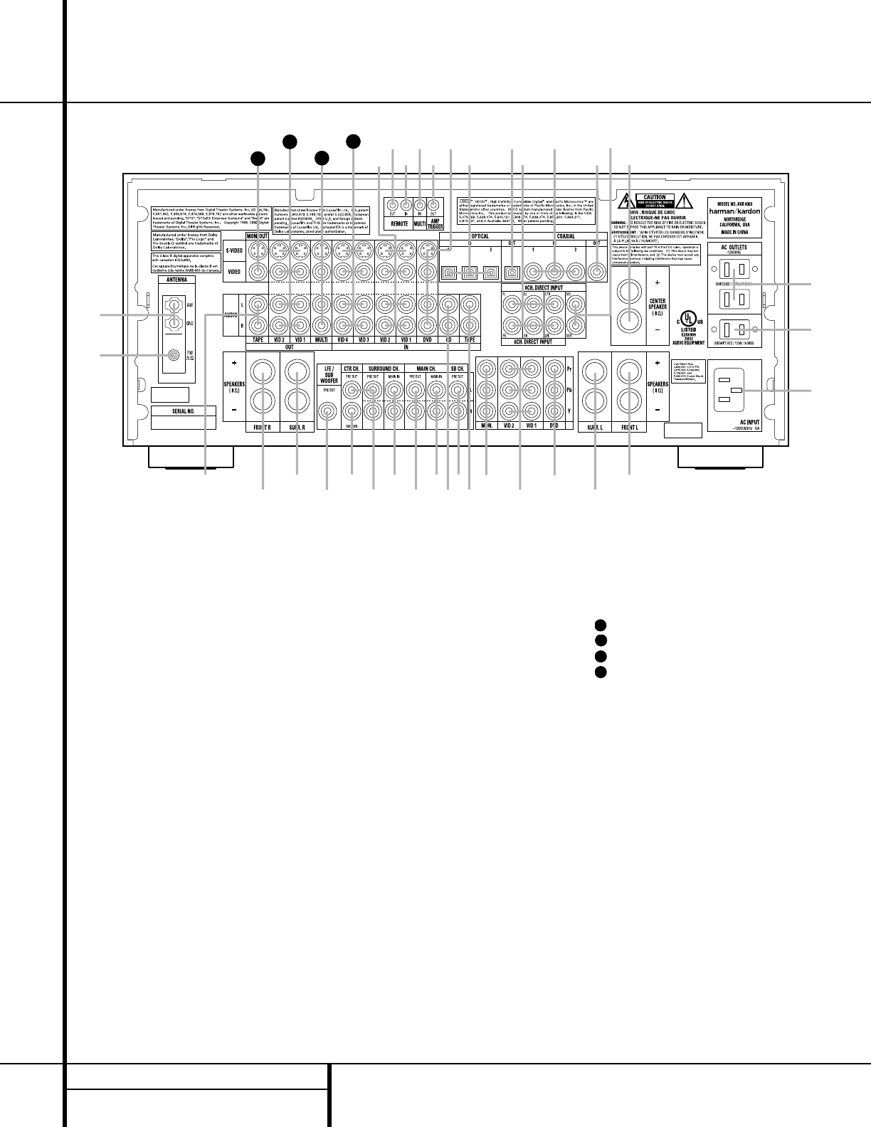
Optical or Coaxial Inputs &(be of the
AVR 8000. No demodulator is required for use
with DVD players or DTS-encoded laser discs.
DTS
DTS is another digital audio system that is
capable of delivering 5.1 or 6.1 discrete or
matrix sound field reproduction. Although both
DTS and Dolby Digital are digital, they use dif-
ferent methods of encoding the signals, and
thus they require different decoding circuits to
convert the digital signals back to analog.
DTS-encoded soundtracks are available on
select DVD and LD discs, as well as on special
audio-only DTS discs. You may use any LD or
CD player equipped with a digital output to
play DTS-encoded discs with the AVR 8000. All
that is required is to connect the players out-
put to either an
Optical or Coaxial Input on
the rear panel
be or front panel &(.
In order to listen to DVDs encoded with DTS
soundtracks, the DVD player must be compati-
ble with the DTS signal as indicated by a DTS
logo on the players front panel. Early DVD
players may not be able to play DTS-encoded
DVDs. This does not indicate a problem with
the AVR 8000, as some players cannot pass
the DTS signal through to the digital outputs.
If you are in doubt as to the capability of your
DVD player to handle DTS discs, consult the
players owners manual.
Selecting a Digital Source
To utilize either digital mode, you must have
properly connected a digital source to the
AVR 8000. Connect the digital outputs from
DVD players, HDTV receivers, satellite systems
or CD players to the
Optical or Coaxial
Inputs
&(be. In order to provide a
backup signal and a source for analog stereo
recording, the analog outputs provided on digi-
tal source equipment should also be connected
to their appropriate inputs on the AVR 8000 rear
panel (e.g., connect the analog stereo audio out-
put from a DVD to the
DVD Audio Inputs f
on the rear panel when you connect the
sources digital outputs).
If you have not already configured an input for
a digital source using the on-screen menus as
shown on page 20, first select the input using
the remote or front panel controls as outlined
in this manual. Next, select the digital source
30
32
31
30
30
31
32
by pressing the Digital Select Button
and then using the
/
¤
Buttons mp on
the remote or the
Selector Buttons 7$
on the front panel to
choose any of the
OPTICAL or COAXIAL
inputs, as they
appear in the
Upper Display Line A or
on-screen display. When the digital source
is playing, the AVR 8000 will automatically
detect which type of digital data stream is
being decoded and display that information
in the
Upper Display Line A.
Digital Bitstream Indicators
When a digital source is playing, the AVR 8000
senses the type of bitstream data that is
present. Using this information, the correct
surround mode will automatically be selected.
For example, DTS bitstreams will cause the unit
to switch to DTS decoding, and Dolby Digital
bitstreams will enable Dolby Digital decoding.
When the unit senses PCM data from CDs
and LDs, it will allow the appropriate surround
sources to be selected manually. Since the
range of available surround modes is dependent
on the type of digital data that is present, the
AVR 8000 uses a variety of indicators to let you
know what type of signal is present. This will
help you to understand the choice of modes.
To help you see which type of digital source is
playing, the
Surround Mode Indicators ¯
also serve as bitstream indications to show
which type of bitstream is present, as well as
the surround mode in use, if applicable.
Dolby Digital: When the green LED next to
the Dolby Digital logo is lit, a Dolby Digital bit-
stream is being received. Depending on the set-
tings on the source player and specific surround
information and number of channels on the
disc, a number of surround modes are possible.
For discs with full 5.1 audio, only the Dolby
Digital and VMAx modes are available.
DTS: When the green LED next to the DTS logo
lights, a DTS bitstream is being received. When
the unit senses this type of data, only the appli-
cable DTS mode may be used.
PCM: When the green LED next to the word
DIGITAL lights, a standard Pulse Code
Modulation, or PCM, signal is being received.
This is the type of digital audio used by conven-
tional compact disc and laser disc recordings.
When a PCM bitstream is present, all modes
except Dolby Digital and DTS are available.
HDCD: When the green LED next to the letters
HDCD is lit in conjunction with the PCM indi-
cator, the CD that is playing is encoded through
the special High Definition Compatible Digital
®
process. HDCD
®
discs use 20-bit encoding and
other proprietary processing to provide the ulti-
mate in CD listening. Note that HDCD process-
ing is only available in the Stereo (Surround
Off) mode.
MP3: When the green LED next to MP3 is lit, a
compatible MPEG 1/Layer 3 digital signal is
being received. This is the popular audio format
used by many computer programs for recording
compressed audio files. When an MP3 bit-
stream is present, the sound will automatically
be played in the Stereo (Surround Off) mode.
The surround modes are not available during
MP3 playback. Note that there are many differ-
ent forms of MP3 encoding available and the
format is used at a number of different bit
rates. The AVR 8000 may not be compatible
with all forms of MP3, particularly when the
data file is encoded at 128 kb/s or above.
Speaker/Channel Indicators
In addition to the bitstream indicators, the
AVR 8000 features a set of unique channel-
input indicators that tell you how many chan-
nels of digital information are being received
and/or whether the digital signal is interrupted.
(See Figure 11.)
Figure 11
These indicators are the L/C/R/LFE/SL/SR/SBL/
SBR letters that are inside the center boxes of
the
Speaker/Channel Input Indicators E
in the front panel Main Information Display
ˆ. When a standard analog signal is in use,
only the Land Rindicators will light, as
analog signals have only left and right channels.
Digital signals, however, may have two, five, six
or seven separate channels, depending on the
program material, the method of transmission
and the way in which it was encoded. When a
digital signal is playing, the letters in these indi-
cators will light in response to the specific sig-
nal being received. It is important to note that
although Dolby Digital, for example, is referred
to as a 5.1system, not all Dolby Digital
DVDs or programs are encoded for 5.1. Thus, it
is sometimes normal for a DVD with a Dolby
Digital soundtrack to trigger only the Land
Rindicators.
NOTE: Many DVD discs are recorded with both
5.1and 2.0 versions of the same sound-
track. When playing a DVD, always be certain
to check the type of material on the disc. Most
discs show this information in the form of a
listing or icon on the back of the disc jacket.
When a disc does offer multiple soundtrack
choices, you may have to make some adjust-
ments to your DVD player (usually with the
Audio Select button or in a menu screen
on the disc) to send a full 5.1 feed to the
AVR 8000. It is also possible for the type of
signal feed to change during the course of a
DVD playback. In some cases, the previews
of special material will only be recorded in
2.0 audio, while the main feature is available
in 5.1 audio. The AVR 8000 will automatically
sense changes to the bitstream and channel
count and reflect them in these indicators.
The letters used by the
Speaker/Channel
Input Indicators
E also flash to indicate
when a bitstream has been interrupted. This
will happen when a digital input source is
selected before the playback starts, or when a
digital source such as a DVD is paused. The
flashing indicators remind you that the play-
back has stopped due to the absence of a digi-
tal signal and not through any fault of the
AVR 8000. This is normal, and the digital play-
back will resume once the playback is started
again.
Night Mode
A special feature of Dolby Digital is the Night
mode, which enables specially encoded Dolby
Digital input sources to be played back with full
digital intelligibility while reducing the mini-
mum peak level by
1
/4 to
1
/3. This prevents
abruptly loud transitions from disturbing others,
without reducing the impact of the digital
source. The Night mode is available only when
Dolby Digital signals with special data are
being played.
The Night mode may be engaged when a Dolby
Digital DVD is playing by pressing the
Night
32 OPERATION
Operation
®
, HDCD
®
, High Definition Compatible Digital
®
and Pacific Microsonics
are either registered trademarks or trademarks of Pacific Microsonics, Inc., in the United States
and/or other countries. HDCD system manufactured under license from Pacific Microsonics, Inc.
33 OPERATION
Operation
Mode Button k on the remote. Next, press
the
/
¤
Buttons mp to select either
the middle range or full compression versions
of the Night mode. To turn the Night mode off,
press the
/
¤
Buttons mp until the
message in the lower third of the video display
and in the
Lower Display Line B reads D-
RANGE OFF
.
The Night mode may also be selected to always
be on at either level of compression using the
options in the
DOLBY menu. See page 23
for information on using the menus to set this
option.
IMPORTANT NOTES ON DIGITAL
PLAYBACK:
When the digital playback source is stopped,
or in a pause, fast forward or chapter search
mode, the digital audio data will momentarily
stop, and the channel position letters inside the
Speaker/Channel Input Indicators E will
flash. This is normal and does not indicate a
problem with either the AVR 8000 or the
source machine. The AVR 8000 will return to
digital playback as soon as the data is avail-
able and when the machine is in a standard
play mode.
Although the AVR 8000 will decode virtually all
DVD movies, CDs and HDTV sources, it is possi-
ble that some future digital sources may not be
compatible with the AVR 8000.
Note that not all digitally encoded programs
contain full 5.1 or 6.1 channel audio. Consult
the program guide that accompanies the DVD
or laser disc to determine which type of audio
has been recorded on the disc. The AVR 8000
will automatically sense the type of digital sur-
round encoding used and adjust to
accommodate it.
When a digital source is playing, you may not
be able to select some of the analog surround
modes such as Dolby Pro Logic II, Dolby 3,
Stereo, Hall, Theater or Logic 7.
When a Dolby Digital or DTS source is play-
ing, it is not possible to make an analog
recording using the
Tape £ and Video 1 or
Video 2 Outputs . However, the digital
signals will be passed through to the
Digital
Audio Outputs
ad.
PCM Audio Playback
PCM (Pulse Code Modulation) is the noncom-
pressed digital audio system used for compact
discs and laser discs. It is also the format used
as an output by audio transcoders such as the
Harman Kardon DAL 150. The digital circuits in
the AVR 8000 are capable of high-quality digi-
tal-to-analog decoding, and they may be con-
nected directly to the digital audio output of
your CD or LD player.
Connections may be made to either the rear
panel
Optical or Coaxial Inputs eb or
the front panel
Digital Inputs &(.
To listen to a PCM digital source, first select the
input for the desired source (e.g., CD). Next
press the
Digital Select Button Úqand
then use the
/
¤
Buttons mp on the
remote, or the
Selector Buttons 7$ on the
front panel, until the desired choice appears in
the
Main Information Display ˆ.
During PCM playback, you may select any
Surround mode except Dolby Digital or DTS.
When an HDCD-encoded disc is being played
and the DVD or CD player is connected to the
AVR 8000 via a digital connection, select
Surround Off as the Surround mode to enjoy
the benefits of the HDCD process.
MP3 Audio Playback
The AVR 8000 is one of the few receivers
equipped for onboard decoding for the MP3
audio format used by computers and portable
audio devices. Also, some new CD players are
capable of playing back optical discs that are
recorded with MP3, rather than standard CD
audio information. By offering MP3 decoding,
the AVR 8000 is able to deliver precise conver-
sion of the digital signals to an analog output,
along with the benefits of listening to the MP3
audio through the AVR 8000s high-current
amplifier and the speakers from your surround
system, rather than the smaller speakers and
low-powered amplifiers typically used with
computers.
To take advantage of the AVR 8000s MP3
capabilities, simply connect the PCM output of
a computers sound card or the PCM output of
a portable digital audio device to either the
rear panel
Digital Inputs be or the front
panel
Digital Inputs &(. When the digital
signal is available, the green LED next to the
MP3 indication in the
Surround Mode
Indicators
¯ will light, and the audio will
begin playing.
NOTES:
The AVR 8000 is only capable of playing sig-
nals in the MP3 (MPEG 1/Layer 3) format. It is
not compatible with other computer audio
codecs.
The digital audio input signal may be either
optical or coaxial, but the signal must be in the
PCM format. Direct connection of USB or serial
data outputs is not possible, even though the
signals are in the MP3 format. If you have any
questions about the data output format from
your computer or a sound card, check with the
devices owners manual or contact the manu-
facturers technical support area.
If your computer or sound cards digital out-
put is not capable of direct connection to the
AVR 8000, you may use an optional, external
transcoder, such as those available from
Harman Kardon, to convert the USB output of
a computer to a format compatible with the
AVR. Contact your Harman Kardon dealer for
additional details.
Due to the wide variation in MP3 formats
and encoding speeds, it is possible that the
AVR 8000 may not be compatible with all MP3
input signals. Some may produce unacceptable
results and some may not be decoded. This
is not a fault of either the computer or the
AVR 8000, but rather a by-product of the
unpredictable nature of MP3 playback.
Tuner Operation
The AVR 8000s tuner is capable of tuning AM,
FM and FM Stereo broadcast stations. Stations
may be tuned manually, or they may be stored
as favorite station presets and recalled from a
30-position memory.
Station Selection
1. Press the AM/FM Tuner Select Button
g
ç
on the remote to select the tuner as
an input. The tuner may be selected from the
front panel by either pressing the
Input
Source Selector
% until the tuner is active
or by pressing the
Tuner Band Selector !
at any time.
2. Press the
AM/FM Tuner Select Button
g
ç
or Tuner Band Selector ! again
to switch between AM and FM so that the
desired frequency band is selected.
33
3. Press the FM Mode
^
or Tuner Mode
Button
s to select manual or automatic
tuning.
When the
AUTO Indicator J is illuminated in
the
Main Information Display ˆ the tuner
will only stop at those stations that have a
strong enough signal to be received with
acceptable quality.
When the
AUTO Indicator J is not lit, the
tuner is in a manual mode and will stop at each
frequency increment in the selected band.
4. To select stations, press the
Tuning
Selector Button
)
u
é
. When the
AUTO Indicator J is illuminated, press the
button for two seconds and then release to
cause the tuner to search for the next highest
or lowest frequency station that has an accept-
able signal. When tuning FM stations in the
Auto mode, the tuner will only select stereo
stations. To tune to the next station, press the
button again. If the
STEREO Indicator H
is not lit, tap the Tuning Selector Button
)
u
é
to advance one frequency
increment at a time, or press and hold it to
locate a specific station. When the
TUNED
Indicator
I lights, the station is properly
tuned and should be heard with clarity.
5. Stations may also be tuned directly by press-
ing the
Direct Button t, and then pressing
the
Numeric Keys
r
that correspond to the
stations frequency. The desired station will
automatically be tuned. If you press an incor-
rect button while entering a direct frequency,
press the
Clear Button to start over.
NOTE: When the FM reception of a station is
weak, audio quality will be increased by switch-
ing to Mono mode by pressing the
FM Mode
Button
^
s
until the STEREO Indicator
H goes out.
Preset Tuning
Using the remote, up to 30 stations may be
stored in the AVR 8000s memory for easy
recall using the front panel controls or the
remote.
To enter a station into the memory, first tune
the station using the steps outlined above.
Then:
1. Press the
Memory Button on the
remote. Note that the
MEMORY Indicator G
will be illuminated and flash in the Main
Information Display
ˆ.
2. Within five seconds, press the
Numeric
Keys
r corresponding to the location where
you wish to store this stations frequency. Once
entered, the preset number will appear in the
Main Information DIsplay ˆ.
3. Repeat the process after tuning any additional
stations to be preset.
Recalling Preset Stations
To manually select a station previously
entered in the preset memory, press the
Numeric Keys r that correspond to the
desired stations memory location.
To manually tune through the list of stored
preset stations one by one, press the
Preset
Stations Selector Buttons
#
©
on
the front panel or remote.
Tape Recording
In normal operation, the audio or video source
selected for listening through the AVR 8000 is
sent to the record outputs. This means that any
program you are watching or listening to may
be recorded simply by placing machines con-
nected to the outputs for
Tape Outputs £ or
Video 1/Video 2 Outputs in the record
mode.
When a digital audio recorder is connected to
the
Digital Audio Outputs ad, you
are able to record the digital signal using a CD-R,
MiniDisc or other digital recording system.
NOTES:
The digital outputs are active only when a
digital signal is present, and they do not con-
vert an analog input to a digital signal, or
change the format of the digital signal. In
addition, the digital recorder must be com-
patible with the output signal. For example,
the PCM digital input from a CD player may
be recorded on a CD-R or MiniDisc, but Dolby
Digital or DTS signals may not.
Please make certain that you are aware of
any copyright restrictions on any material you
copy. Unauthorized duplication of copyrighted
materials is prohibited by federal law.
Front Panel Connections
In addition to the rear panel digital outputs, the
AVR 8000 offers Harman Kardons exclusive
configurable front panel output jack feature. For
easy connection of portable devices, you may
switch the front panel
Video 5 Jacks from
an input to an output by following these steps:
1.Press the
OSD Button v to view the
MASTER MENU (Figure 1).
2.Press the
Set Button o to enter the
IN/OUT SETUP menu (Figure 2).
3.Press the
¤
Button p so that the on-
screen
cursor is next to VIDEO 5.
4.Press the
Set Button o and then press
either of the
/
Buttons n/ so that
the word
OUT is highlighted.
5.Press the
Set Button o to enter the
change.
6.Press the
OSD Button v to exit the
menus and return to normal operation.
Note that once the setting is made, the
Input/Output Status Indicator Ô will turn
red, indicating that the jacks are now an out-
put, instead of in the default setting as an
input. Once changed to an output, the setting
will remain as long as the AVR 8000 is turned
on, unless the setting is changed in the OSD
menu system, as described above. Note, howev-
er, that once the AVR 8000 is turned off, the
setting is cancelled. When the unit is turned on
again, the front panel jacks will return to their
normal default setting as an input. If you wish
to use their jacks as an output at a future time,
the setting must be changed again using the
OSD menu system, as described above.
Output Level Trim Adjustment
Normal output level adjustment for the
AVR 8000 is established using the test tone,
as outlined on pages 24 through 26. In some
cases, however, it may be desirable to adjust the
output levels using program material such as a
test disc, or a selection you are familiar with.
Additionally, the output level for the subwoofer
can only be adjusted using this procedure.
To adjust the output levels using program
material, first set the reference volume for
the front left and front right channels using the
Volume Control Ù
î
.
If you are using a disc with test signals or an
external signal generator as the source from
which to trim the output levels, you may use
the EzSet feature of the remote to guide you
to the correct SPL level. To use the remote for
42
39
33
35
37
36
34 OPERATION
Operation
35 OPERATION
Operation
this purpose, press and quickly release the
SPL Select Button to activate the
sensor. While the test tone is circulating, the
Program/SPL Indicator c will change
color to indicate the level. Adjust the level as
shown above until the LED lights green for all
channels. When it is red the level is too high;
when it is amber the level is too low. Press the
SPL Select Button to turn the sensor
and indicator off.
Once the reference level has been set, press
the
Channel Select Button
l
and note
that
FRONT L LEV will appear in the
Main Information Display ˆ. To change
the level, first press the
Set Button o, and
then use the
/
¤
Buttons
mp
to raise
or lower the level. DO NOT use the volume
control, as this will alter the reference setting.
Once the change has been made, press the
Set Button o and then press the
/
¤
Buttons
mp
to select the next output
channel location that you wish to adjust. To
adjust the subwoofer level, press the
/
¤
Buttons
mp
until WOOFER LEV
appears in the Main Information Display ˆ
or on-screen display.
Repeat the procedure as needed until all chan-
nels requiring adjustment have been set. When
all adjustments have been made and no further
adjustments are made for five seconds, the
AVR 8000 will return to normal operation.
The channel output for any input may also be
adjusted using the full-OSD on-screen menu
system. First, set the volume to a comfortable
listening level using the
Volume Control
Ù
î
. Then, press the OSD Button v
to bring up the MASTER MENU (Figure 1).
Press the
¤
Button p until the on-screen
cursor is next to the CHANNEL ADJUST
line. Press the Set Button o to activate the
CHANNEL ADJUST menu.
Once the menu appears on your video screen,
first use the
/
¤
Buttons mp to move
the on-screen
cursor so that it is next to the
TEST TONE line. Press the
/
Buttons
n so that OFF is highlighted.This will
turn off the test tone and allow you to use your
external test disc or other source material as
the reference. Then, use the
/
¤
Buttons
mp to select the channels to be adjusted.
At each channel position, use the
/
Buttons
n to change the output level. Remember,
the goal is to have the output level at each
channel be equal when heard at the listening
position.
If you wish to reset all the levels to their origi-
nal factory default of 0dB offset, press the
/
¤
Buttons mp so that the on-screen
cursor is next to the
CHANNEL RESET
line and press the
/
Buttons n so
that the word
ON is highlighted. After the lev-
els are reset, resume the procedure outlined
above to reset the levels to the desired set-
tings. When all adjustments are done, press the
/
¤
Buttons mp to move the on-screen
cursor so that it is next to BACK TO
MASTER MENU
and then press the Set
Button
o if you wish to go back to the
main menu to make other adjustments. If you
have no other adjustments to make, press the
OSD Button v to exit the menu system.
NOTE: The output levels may be separately
trimmed for each digital and analog surround
mode. If you wish to have different trim levels for
a specific mode, select that mode and then follow
the instructions in the steps shown earlier.
6-Channel/8-Channel Direct Input
The AVR 8000 is equipped for future expansion
through the use of optional, external adapters for
formats that the AVR 8000 may not be capable
of processing or to allow connection to the
output of high-resolution optical audio playback
systems such as DVD-Audio or SACD. When
a device with six-channel outputs (5.1 audio)
is used, connect the source device to the
6-Channel Direct Inputs c. When a device
with eight-channel outputs (7.1) audio is used,
connect the additional Surround Back Left (SBL)
and Surround Back Right (SBR) outputs to the
8-Channel Direct Inputs · on the AVR.
To select these inputs, press the
6-Channel/
8-Channel Direct Button
@ until the
desired input configuration appears in the
Main Information Display ˆ.
Note that when the 6-Channel or 8-Channel
Direct Input is in use, you may not select a sur-
round mode, as the external decoder deter-
mines the processing in use. In addition, there
is no signal at the record outputs or bass man-
agement when the 6-Channel or 8-Channel
Direct Input is in use.
Memory Backup
This product is equipped with a memory backup
system that preserves the system configuration
information and tuner presets if the unit is
accidentally unplugged or subjected to a power
outage. This memory will last for approximately
two weeks, after which time all information
must be reentered.
45
39
39
39
42
43
43
The AVR 8000 is equipped with a number of
advanced features that add extra flexibility to
the units operation. While it is not necessary
to use these features to operate the unit, they
provide additional options that you may wish
to use.
Speaker Reset
In some cases you may wish to reset the speaker
configuration to the factory default settings.
To restore those settings you will need to make
an adjustment in the
ADVANCED menu. To
recall that menu, press the
OSD Button v
to bring the MASTER MENU (Figure 1)
to the screen. Press the
¤
Button p until
the
cursor is next to the ADVANCED
line. Press the Set Button o to enter the
ADVANCED menu (Figure 12).
Figure 12
To reset the speaker configuration to the
factory default, press the
Button
so that the word ON is highlighted and
then press the
Set Button o.
Once the speaker settings are reset you may
press the
¤
Button p to make any of the
other adjustments available on this menu. If no
other adjustments are needed, press the
OSD
Button
v to exit the menu system.
Display Brightness
The AVR 8000s Main Information Display
ˆ is set at a default brightness level that is
sufficient for viewing in a normally lit room.
However, in some home theater installations,
you may wish to occasionally lower the bright-
ness of the display, or turn it off completely.
To change the display brightness setting for a
specific listening session, you will need to make
an adjustment in the
ADVANCED menu. To
start the adjustment, press the
OSD Button
v to bring the MASTER MENU to the
screen. Press the
¤
Button p, until the on-
screen
cursor is next to the
ADVANCED
line. Press the Set Button o to enter the
ADVANCED menu (Figure 12).
To change the brightness setting, at the
ADVANCED menu, make certain that the
on-screen
cursor is next to the VFD line,
and press the
Button until the desired
brightness level is highlighted in the video dis-
play. When
FULL is highlighted, the display is
at its normal brightness. When
HALF is high-
lighted, the display is at half the normal bright-
ness level. When
OFF is highlighted, all of the
indicators in the
Main Information Display
ˆ will go dark. Note, however, that the green
LEDs for the
Input Indicators ı and the
Surround Mode Indicators ¯, as well as
for the
Power Indicator 3, will always remain
lit to remind you that the unit is turned on.
Once the desired brightness level is selected, it
will remain in effect until it is changed again or
until the unit is turned off.
If you wish to make other adjustments, press
the
/
¤
Buttons mp until the on-screen
cursor is next to the desired setting or the
BACK TO MASTER MENU line and
press the
Set Button o. If you have no
other adjustments to make, press the
OSD
Button
v to exit the menu system.
Turn-On Volume Level
As is the case with most audio/video receivers,
when the AVR 8000 is turned on, it will always
return to the volume setting in effect when the
unit was turned off. However, you may prefer to
always have the AVR 8000 turn on at a specific
setting, regardless of what was last in use
when the unit was turned off. To change the
default condition so that the same volume level
is always used at turn-on, you will need to
make an adjustment in the
ADVANCED
menu. To start the adjustment, press the OSD
Button
v to bring the MASTER MENU
(Figure 1) to the screen. Press the
¤
Button
p, until the on-screen
cursor is next to the
ADVANCED line. Press the Set Button o
to enter the ADVANCED menu (Figure 12).
At the
ADVANCED menu make certain that
the on-screen
cursor is next to the
VOLUME DEFAULT line by pressing the
/
¤
Buttons mp as needed. Next, press
the
Button so that the word ON is
highlighted in the video display. Next, press the
¤
Button p once so that the on-screen
cursor is next to the DEFAULT VOL SET
line. To set the desired turn-on volume, press
the
/
Buttons n until the desired
volume level is shown on the
DEFAULT
VOL SET
line. Note that this setting may
NOT be made with the regular volume controls.
NOTE: Since the setting for the turn-on volume
cannot be heard while the setting is being
made, you may wish to determine the setting
before making the adjustment. To do this, listen
to any source and adjust the volume to the
desired level using the regular
Volume
Controls
Ù
î
. When the desired
volume level to be used at turn-on is reached,
make a note of the setting as it appears in the
lower third of the video screen or in the
Lower
Display Line
B. (A typical volume level will
appear as a negative number such as 25dB.)
When making the adjustment, use the
/
Buttons n to enter this setting.
Unlike some of the other adjustments in this
menu, the turn-on volume default will remain
in effect until it is changed or turned off in this
menu, even when the unit is turned off.
If you wish to make other adjustments, press
the
/
¤
Buttons mp until the on-screen
cursor is next to the desired setting or the
BACK TO MASTER MENU line and
press the
Set Button o. If you have no
other adjustments to make, press the
OSD
Button
v to exit the menu system.
Semi-OSD Settings
The semi-OSD system places one-line messages
at the lower third of the video display screen
whenever the Volume, Input Source, Surround
mode or tuner frequency of any of the configu-
ration settings are changed. The semi-OSD sys-
tem is helpful in that it enables you to have
feedback on any control changes or remote
commands using the video display when it is
difficult to view the front panel displays.
However, you may occasionally prefer to turn
these displays off for a particular listening ses-
sion. You may also want to adjust the length of
time the displays remain on the screen. Both of
those options are possible with the AVR 8000.
To turn off the semi-OSD system, youll need
to make an adjustment in the
ADVANCED
menu (Figure 12). To start the adjustment, press
the
OSD Button v to bring the MASTER
MENU
to the screen. Press the ¤ Button p,
until the on-screen
¤ cursor is next to the
ADVANCED line. Press the Set Button o
to enter the ADVANCED menu.
At the
ADVANCED menu, make certain that
the on-screen
cursor is next to the SEMI
OSD DEFAULT
line by pressing the
/
¤
Buttons mp as needed. Next, press the
Button so that the word OFF is high-
lighted in the video display.
39
39
42
39
39
39
39
* ADVANCED *
SPEAKER RESET :OFF ON
VFD :FULL HALF OFF
VOLUME DEFAULT:OFF ON
DEFAULT VOL SET:25dB
SEMI OSD :OFF ON
SEMI OSD TIME OUT: 3SEC
FULL OSD TIME OUT:20SEC
BACK TO MASTER MENU
36 ADVANCED FEATURES
Advanced Features
37 ADVANCED FEATURES
Advanced Features
Note that this setting is temporary and will
remain active only until it is changed or until
the AVR 8000 is turned off. Once the unit is
turned off, the semi-OSD displays will remain
activated, even if they were switched off for the
previous listening session.
To change the length of time that the semi-OSD
displays remain on the screen, go to the
ADVANCED menu as outlined earlier, and
press the
/
¤
Buttons mp as needed,
until the on-screen
cursor is next to the
SEMI OSD TIME OUT line. Next, press
the
/
Buttons n until the desired
time in seconds is displayed. Note that unlike
most of the other options in this menu, this is a
permanent setting change, and the time-out
entry will remain in effect until it is changed,
even when the unit is turned off.
If you wish to make other adjustments, press
the
/
¤
Buttons mp until the on-screen
cursor is next to the desired setting or the
BACK TO MASTER MENU line and
press the
Set Button o. If you have no
other adjustments to make, press the
OSD
Button
v to exit the menu system.
Full-OSD Time-Out Adjustment
The FULL OSD menu system is used to
simplify the setup and adjustment of the
AVR 8000, using a series of on-screen menus.
The factory default setting for these menus
leaves them on the screen for 20 seconds after
a period of inactivity before they disappear
from the screen (Time-Out). Time-Out is a safety
measure to prevent image retention of the
menu text in your monitor or projector, which
might happen if it were left on indefinitely.
However, some viewers may prefer a slightly
longer or shorter period before the Time-Out
display.
To change the full-OSD Time-Out, you will need
to make an adjustment in the
ADVANCED
menu (Figure 12). To start the adjustment, press
the
OSD Button v to bring the MASTER
MENU
to the screen. Press the ¤ Button
p, until the on-screen ¤ cursor is next to the
ADVANCED line. Press the Set Button o
to enter the ADVANCED menu (Figure 12).
At the
ADVANCED menu (Figure 12) make
certain that the on-screen
cursor is next to
the
FULL OSD TIME OUT line by press-
ing the
/
¤
Buttons mp as needed.
Next, press the
/
Buttons n until the
desired time is displayed in seconds. Note that
unlike most of the other options in this menu,
this is a permanent setting change, and the
Time-Out entry will remain in effect until it is
changed, even if the unit is turned off.
If you wish to make other adjustments, press
the
/
¤
Buttons mp until the on-screen
cursor is next to the desired setting or the
RETURN TO MASTER MENU line and
press the
Set Button o. If you have no
other adjustments to make, press the
OSD
Button
v to exit the menu system.
39
39
38 MULTIROOM OPERATION
Multiroom Operation
The AVR 8000 is fully equipped to operate
as the control center for a multiroom system
with optional remote external infrared (IR) sen-
sors, speakers and power amplifiers. Although
some multiroom installations will require the
services of a specially trained installer, it is pos-
sible for the average do-it-yourself hobbyist to
install a simple remote room system.
Installation
The key to remote room operation is to link the
remote room to the AVR 8000s location with
wire for an infrared link and speakers or an
amplifier. For installation instructions for
Multiroom use, see page 16.
Multiroom Setup
Once the audio and IR link connections have
been made, the AVR 8000 needs to be config-
ured for multiroom operation using the steps
below. Press the
OSD Button v to bring the
MASTER MENU (Figure 1) to the screen.
Press the
¤
Button p, until the on-screen
cursor is next to the MULTI-ROOM line.
Press the
Set Button o to enter the
MULTI-ROOM menu (Figure 13).
Figure 13
When the MULTI-ROOM menu appears,
the on-screen
cursor will be at the
MULTI-ROOM line. Since this line is used
to turn the system on and off, dont make an
adjustment here unless you wish to turn the
system on at this time. To turn the system on,
press the
Button so that ON is high-
lighted. If you do not wish to turn the system on
at this time or to proceed to the next step, press
the
¤
Button p once so that the on-
screen cursor is next to the
MULTI IN line.
At the
MULTI IN line, press the
/
Buttons n until the desired input
to the multiroom system appears in the high-
lighted video. When the selection has been
made, press the
¤
Button p once so
that the
on-screen cursor is next to the
MULTI VOL line.
At the
MULTI VOL line, press the
/
Buttons n until the desired volume
level for the multiroom system is entered. DO
NOT use the regular volume control knobs for
this setting. When all settings for the multiroom
setup have been made, press the
/
¤
Buttons mp until the on-screen
cursor
is next to the
BACK TO MASTER MENU
line. If you have no other adjustments to make,
press the
OSD Button v to exit the menu
system.
Multiroom Operation
When operating the AVR 8000 from a remote
room location where an IR sensor link has been
connected to the AVR 8000s rear panel
Multizone IR Input h, you may use either
the main remote control or the Zone II remote.
To turn on the multiroom feed, press any of the
Input Selector buttons on the Zone II remote
∫ç∂
or the main remote
ef
g
. Press the AVR Selector f
to
turn the unit on to the last source, or any of the
other Selector buttons to turn on to a specific
source.
As long as an IR feed to the AVR 8000 has
been established from the remote room, using
any of the buttons on either remote will control
the remote location volume
î
, change
the tuner frequency
u
É
, change the tuner
preset
©
or mute the output
˚
.
If the
Remote IR Output Jack j on the
AVR 8000 is connected to an IR Input jack on
compatible Harman Kardon audio components
such as CD, DVD or cassette players, the trans-
port functions of those machines may also be
controlled using the
Transport Controls
z`
ƒ˙∆
on either remote control.
To turn the system off from the remote room,
press the
Power Off Button a
å
.
Remember that the AVR 8000 may be turned
on or off from the remote room, regardless
of the systems operation or status in the
main room.
NOTE: When the tuner is selected as the
source for the remote zone, any change to the
frequency or preset will also change the station
being listened to in the main room, if the tuner
is in use there. Similarly, if someone in the main
room changes the station, the change will also
impact the remote room.
To activate the feed to the remote room, while
you are in the main listening room where the
AVR 8000 is located, press the
Multiroom
Button
on the remote. Next, press the
Set Button o. Press the
/
¤
Buttons
mp to turn the multiroom feed on or off.
When the multiroom system is on, the
Multiroom Indicator D will light in the
Main Information Display ˆ, and the
Main Information Display ˆ or OSD will
display
MULTI ON. Press the Set Button
o to enter the setting.
When the multiroom system is turned on, the
input selected using the multiroom menu will be
fed to the
Multizone Output jacks on the
rear panel. The volume will be as set in the pre-
vious selection, although it may also be adjusted
using an optional IR sensor and the Zone II
remote in the remote location or on the optional
audio power amplifier connected to the
Multizone Output jacks.
Once the multiroom system is turned on, it will
remain on even if the AVR 8000 is placed in
the Standby mode in the main room by press-
ing the
Power Off Button
å
or the
System Power Control 2 on the front
panel. To turn off the multiroom system, even
when the AVR is in Standby mode in the main
listening room, press the
Multiroom Button
and then the Set Button o. Press
the
/
¤
Buttons mp so that the
Multiroom Indicator D in the Main
Information Display
ˆ goes out, and the
Main Information Display ˆ or OSD will
display
MULTI OFF. Press the Set Button
o to enter the setting and turn the unit off.
Even when the AVR 8000 is turned off in the
main room, the multiroom system may be
turned on at any time by pressing the
Multiroom Button , or any of the
Selector Buttons
∫ç∂
in the
remote room.
41
41
32
32
41
46
35
42
45
39
39
39
* MULTI-ROOM *
MULTI-ROOM:OFF ON
MULTI IN :FM PRESET 01
MULTI VOL :25dB
BACK TO MASTER MENU
39 PROGRAMMING THE REMOTE
Programming the Remote
The AVR 8000 is equipped with a powerful
remote control that will control not only the
receivers functions, but also most popular
brands of audio and video equipment, includ-
ing CD players, cassette decks, TV sets, cable
boxes, VCRs, satellite receivers and other home-
theater equipment. Once the AVR 8000s
remote is programmed with the codes for the
products you own, it is possible to eliminate
most other
remotes and replace them with the
convenience of a single, backlit universal remote
control.
Programming the Remote
The AVR 8000 remote is factory-programmed
for all AVR functions, as well as those of most
Harman Kardon CD changers, DVD players,
CD players and cassette decks. In addition, by
following one of the methods below, you may
program the remote to operate a wide range
of devices from other manufacturers.
Direct Code Entry
This method is the easiest way to program your
remote to work with different products.
1. Use the tables in the following pages to
determine the three-digit code or codes
that match both the product type (e.g.,
VCR, TV) and the specific brand name. If
there is more than one number for a brand,
make note of the different choices.
2. Turn on the unit you wish to program into
the AVR 8000 remote.
3. Press and hold both the
Input Selector
e for the product you wish to control
(e.g., VCR, TV) and the
Mute Button
at the same time. When the Program/SPL
Indicator
c turns amber and begins
flashing and the red light under the
Input
Selector
e stays lit, release the buttons.
It is important that you begin the next step
within 20 seconds.
4. Point the AVR 8000s remote towards the
unit to be programmed, and enter the first
three-digit code number using the
Numeric
Keys
r. If the unit turns off, the correct
code has been entered. Press the
Input
Selector
e again, and note that the red
light will flash three times before going dark
to confirm the entry.
5. If the device to be programmed in does
NOT turn off, continue to enter three-digit
code numbers until the equipment turns off.
At this point, the correct code has been
entered. Press the
Input Selector e
again and note that the red light under the
Input Selector e will flash three times
before going dark to confirm the entry.
6. Try all of the functions on the remote to
make certain that the product operates
properly. Keep in mind that many manufac-
turers use a number of different combina-
tions of codes, so it is a good idea to make
certain that not only the Power control, but
the volume, channel and transport controls
work as they should. If functions do not
work properly, you may need to use a dif-
ferent remote code.
7. If a code cannot be entered to turn the
unit off, if the code for your product does
not appear in the tables in this manual, or
if not all functions operate properly, try
programming the remote with the Auto
Search Method.
Auto Search Method
If the unit you wish to include in the AVR 8000s
remote is not listed in the code tables in this
manual or if the code does not seem to operate
properly, you may wish to program the correct
code using the Auto Search method that follows:
1. Turn on the unit that you wish to include in
the AVR 8000 remote.
2. Press the
Input Selector e for the type
of product to be entered (e.g., VCR, TV) and
the
Mute Button at the same time.
Hold both buttons until the
Program/SPL
Indicator
c turns amber and begins
flashing and the red light under the
Input
Selector
e stays lit. Note that the next
step must take place while the red light is
on, and it must begin within 20 seconds
after the light appears.
3. Point the AVR 8000 remote towards the
unit to be programmed, and press either the
or
¤
Button mp. Each press will
send out a series of codes from the remotes
built-in database. When the unit being pro-
grammed turns off, release the
/
¤
Button mp, as that is your indication
that the correct code is in use.
4. Press the
Input Selector e, and note
that the red light under the
Input Selector
e will flash three times before going dark
to confirm the entry.
5. Try all of the functions on the remote to
make certain that the product operates.
Keep in mind that many manufacturers use
a number of different combinations of
codes, and it is a good idea to make certain
that not only the Power control works, but
also the volume, channel and transport con-
trols, as appropriate. If all functions do not
work properly, you may need to Auto-
Search for a different code, or enter a code
via the Direct Code Entry method.
Code Readout
When the code has been entered using the
Auto Search method, it is always a good idea to
find out the exact code so that it may be easily
reentered if necessary. You may also read the
codes to verify which device has been pro-
grammed to a specific Control Selector button.
1. Press and hold both the
Input Selector
e for the device you wish to find the
code for and the
Mute Button at
the same time. Note that the
Program/
SPL Indicator
c will initially turn
amber and begin flashing, and the red
light under the
Input Selector e will
stay lit. Release the buttons and begin
the next step within 20 seconds.
2. Press the
Set Button o. The Program/
SPL Indicator
c will then blink green in
a sequence that corresponds to the three-
digit code, with a one-second pause between
each digit. Count the number of blinks
between pauses to determine the digit of the
code. One blink indicates the number 1, two
blinks for the number 2, and so forth. Ten
blinks are used to indicate a 0.
Example: One blink, followed by a one-second
pause, followed by six blinks, followed by a
one-second pause, followed by ten blinks indi-
cates that the code has been set to 160.
For future reference, enter the Setup Codes for
the equipment in your system here:
DVD ____________ CD ________________
VID1/VCR ________ VID2/TV __________
VID3/CBL ________ VID3/SAT__________
VID4 ____________ TAPE ____________
46
Learning Codes
In addition to using codes from the remotes
internal code library, the AVR 8000s remote is
able to learncodes from remotes that may
not be in the code library. In addition, you may
use this function to learn overthe codes
from a preprogrammed device to add functions
not included in the preprogrammed codes. To
learn or transfer codes from an IR remote to
the AVR 8000s remote, follow these steps:
1. Place the front of the original remote with
the code being sent so that it is facing the
IR Transmitter Window b on the
AVR 8000 remote head-to-head. The
remotes should be between one and three
inches apart.
2. Select the button on the remote that you
wish to use as the device selector for the
codes about to be entered. This may be any
of the
Input Selectors e.
3. Press the
Input Selector e button
chosen and the
Learn Button at the
same time. Hold these buttons until the
Program/SPL Indicator c flashes amber
and the light under the device selector but-
ton turns red. Release the buttons.
4. Press the button on the AVR 8000 remote
that you wish to program. Note that the
Program/SPL Indicator c will stop
flashing.
5. Within five seconds, press and hold the but-
ton on the original remote that you wish to
teachinto the AVR 8000 remote. When
the
Program/SPL Indicator c turns
green three times, release the button. Note
that the Program Indicator will then begin to
flash amber again.
NOTE: If the Program/SPL Indicator c
turns red during Step 4 or 5, the program-
ming was not successful. Repeat the steps to
see if the code will take.
6. Repeat Steps 4 and 5 for each button on the
source remote that you wish to transfer to
the AVR 8000 remote.
7. Once all codes have been transferred from
the original source remote to the AVR 8000
remote, press the
Learn Button .
8. Repeat Steps 1 through 7 for any additional
remotes you wish to teachinto the
AVR 8000 Remote.
Erasing Learned Codes
The AVR 8000s remote allows you to remove or
erase the code learned into a single button for a
single device, to remove or erase the code set for
all the codes that have been programmed into
specific device buttons, or to erase all commands
that have been learned to all devices.
To erase a single learned code from within a sin-
gle devices settings, follow these steps:
1. Press and hold both the
Input Selector e
within which the individual button to be
erased has been programmed and the
Learn
Button
.
2. When the red LED under the
Input Selector
turns red and the Program/SPL Indicator
c flashes amber, release the buttons.
3. Press and release the
Input Selector e
again for the device within which the
individual button to be erased has been
programmed.
4. Press the
7 Button r four times.
5. Press and release the individual button for
which the code is to be erased.The
Program/SPL Indicator c will blink
green two times and then return to amber.
6. To erase other buttons within the same
device, press them as noted in Step 5.
7. When all buttons to be erased have been
pressed, press the
Learn Button to
complete the process.
To erase all codes within a single device, follow
these steps:
1. Press and hold both the
Input Selector e
for which you wish to erase the codes and the
Learn Button .
2. When the red LED under the
Input Selector
turns red and the Program/SPL Indicator
c flashes amber, release the buttons.
3. Press and release the
Input Selector e
again for the device whose codes you wish
to erase.
4. Press the
8 Button r four times.
5. The
Program/SPL Indicator c will turn
off and the red light under the
Input
Selector
will flash on and off once to indi-
cate that the codes have been erased.
To erase all codes that have been programmed
to all devices in the remote, follow these steps:
1. Press any
Input Selector e for which you
wish to erase the codes and also the
Learn
Button
.
2. When the red LED under the
Input Selector
turns red and the Program/SPL Indicator
c flashes amber, release the buttons.
3. Press and release the same
Input Selector
e again for the device whose codes you
wish to erase.
4. Press the
9 Button r four times.
5. The
Program/SPL Indicator c will
turn off and the red light under the
Input
Selector
e will flash on and off once to
indicate that the codes have been erased.
Macro Programming
Macros enable you to easily repeat frequently
used combinations of commands with the press
of a single button on the AVR 8000s remote
control. Once programmed, a macro will send
out up to 19 different remote codes in a prede-
termined sequential order enabling you to auto-
mate the process of turning on your system,
changing devices, or other common tasks. The
AVR 8000s remote can store up to five sepa-
rate macro command sequences: one that is
associated with the
Power On Button d
and four more that are accessed by pressing the
Macro Buttons .
1. Press the
Mute Button and the
Macro Button to be programmed
or the
Power On Button d at the same
time. Note that the
AVR Selector f
will light red, and the Program/SPL
Indicator
c will flash amber.
2. Enter the steps for the macro sequence by
pressing the button for the actual command
step. Although the macro may contain up to
19 steps, each button press, including those
used to change devices, counts as a step.
The
Program/SPL Indicator c will flash
green to confirm each button press as you
enter commands.
33
46
33
44
44
44
44
44
44
40 PROGRAMMING THE REMOTE
Programming the Remote
41 PROGRAMMING THE REMOTE
Programming the Remote
NOTE: While entering commands for Power
On/Off of any device during a macro sequence,
press the
Mute Button . DO NOT press the
actual Power button.
3. When all the steps have been entered,
press the
Sleep Button i to enter the
commands. The red light under the
Input
Selectors
ef will blink and then
turn off.
Example: To program the Macro 1 button
so that it turns on the AVR 8000,TV and a
Cable Box, follow these steps:
Press the
Macro 1 Button and
Mute Button at the same time and
then release them.
Note that the
Program/SPL Indicator
c will flash amber.
Press the
AVR Selector f.
Press the
Mute Button to store the
AVR 8000s power on command.
Press the
VID 2 Input Selector Button
e to indicate the next command is for
TV Power On.
Press the
Mute Button to store the
TV Power On Command.
Press the
VID 3 Input Selector Button
e to indicate the next command is for
Cable Power On.
Press the
Mute Button to store the
Cable Power On command.
Press the
Sleep Button i to complete
the process and store the macro sequence.
After following these steps, each time
you press the
Macro 1 Button ,
the remote will send the Power On/Off
command to those three devices.
Erasing Macro Commands
To remove the commands that have been pro-
grammed into one of the Macro buttons, follow
these steps:
1. Press the
Mute Button and the
Macro Button that contains the
commands you wish to erase.
2. Note that the
Program/SPL Indicator
c will flash amber, and the LED under
the
AVR Selector f will turn red.
3. Within ten seconds, press the
Surround
Mode Selector Button
j.
4. The red LED under the
AVR Selector f
will go out, and the Program/SPL
Indicator
c will turn green and flash
three times before it goes out.
5. When the
Program/SPL Indicator c
goes out, the Macro has been erased.
Programmed Device Functions
Once the AVR 8000s remote has been pro-
grammed for the codes of other devices, press
the appropriate
Input Selector e to change
the remote from controlling the AVR 8000 to
controlling the additional product. When you
press any one of the selectors, it will briefly flash
in red to indicate that you have changed the
device being controlled.
When operating a device other than the
AVR 8000, the controls may not correspond
exactly to the function printed on the remote
or button. Some commands, such as the volume
control, are the same as they are with the
AVR 8000. Other buttons will change their
function so that they correspond to a secondary
label on the remote. For example, the Sleep
and Surround mode selector buttons also func-
tion as the Channel Up and Channel Down
buttons when operating most TV sets, VCRs or
cable boxes. The Channel Up/Down indication is
printed directly on the remote. For many stan-
dard CD players, cassette decks, VCRs and DVD
functions, the standard function icons are print-
ed on top of the buttons.
For some products, however, the function of a
particular button does not follow the command
printed on the remote. In order to see which
function a button controls, consult the Function
List tables on pages 44 and 45. To use those
tables, first check the type of device being con-
trolled (e.g., TV, VCR). Next, look at the remote
control diagram pictured at the left. Note that
each button has a number on it.
To find out what function a particular button
has for a specific device, find the button num-
ber on the Function List and then look in the
column for the device you are controlling. For
example, button number 46 is the Direct button
for the AVR 8000, but it is the Favoritebut-
ton for many cable television boxes and satel-
lite receivers. Button number 32 is the Delay
button for the AVR 8000, but the Open/Close
button for CD players.
NOTE: That the numbers used to describe the
button functions at the left for the purposes of
describing how a button operates are a differ-
ent set of numbers than those used in the rest
of this manual to describe the button functions
for the AVR 8000.
1
4
5
6
7
8
9
10
11
12
16
20
24
25
27
28
29
30
31
32
33
34
35
36
37
38
39
40
41
42
43
44
45
46
47
48
49
50
51
52
53
54
55
56
26
17
18
19
23
22
21
13
14
15
2
3
57
58
59
60
61
62
64
63
65
67
66
68
69
70
71
72
33
46
33
46
46
46
46
33
46
Notes on Using the AVR 8000 Remote
With Other Devices
Manufacturers may use different code sets
for the same product category. For that rea-
son, it is important that you check to see
whether the code set you have entered oper-
ates as many controls as possible. If it
appears that only a few functions operate,
check to see whether another code set will
work with more buttons.
When a button is pressed on the AVR 8000
remote, the red light under the
Input
Selector
ef for the product being
operated should flash briefly. If the Device
Control Selector flashes for some but not all
buttons for a particular product, it does NOT
indicate a problem with the remote but rather
that no function is programmed for the but-
ton being pushed.
Volume Punch-Through
The AVR 8000s remote may be programmed to
operate the
Volume Control and Mute
functions of either the TV or the AVR 8000
in conjunction with any of the devices con-
trolled by the remote. For example, since the
AVR 8000 will likely be used as the sound sys-
tem for TV viewing, you may wish to have the
AVR 8000s volume activated, although the
remote is set to run the TV. Either the
AVR 8000 or TV volume control may be associ-
ated with any of the remotes devices. To pro-
gram the remote for Volume Punch-Through,
follow these steps:
1. Press the
Input Selector e for the unit
you wish to have associated with the volume
control and the
Mute Button at the
same time until the red light appears under
the
Input Selector e and note that the
Program/SPL Indicator c will flash
amber.
2. Press the
Volume Up Button and
note that the
Program/SPL Indicator c
will stop flashing and stay amber.
3. Press either the
AVR Selector f or the
Input Selector e, depending on which
systems volume control you wish to have
attached for the punch-through mode. The
Program/SPL Indicator c will blink
green three times and then go out to
confirm the data entry.
Example: To have the AVR 8000s volume
control activated even though the remote
is set to control the TV, first press the
Video 2/TV Input Selector e and the
Mute Button at the same time. Next,
press the
Volume Up Button , fol-
lowed by the
AVR Selector f.
NOTE: Should you wish to return the remote to
the original configuration after entering a
Volume Punch-Through, you will need to repeat
the steps shown above. However, press the same
Input Selector in Steps 1 and 3.
Channel Control Punch-Through
The AVR 8000s remote may be programmed to
operate so that the channel control function for
either the TV, cable or satellite receiver used in
your system may be used in conjunction with
one of the other devices controlled by the
remote. For example, while using and controlling
the VCR, you may wish to change channels on a
cable box or satellite receiver without having to
change the device selected by the AVR 8000 or
the remote. To program the remote for Channel
Control Punch-Through, follow these steps:
1. Press the
Input Selector Button e for
the device you wish to have the channel con-
trol associated with and the
Mute Button
at the same time until the red light
appears under the
Input Selector e and
the
Program/SPL Indicator c flashes
amber.
2. Press the
Volume Down Button .The
Program/SPL Indicator c will stop flash-
ing and stay amber.
3. Press and release the
Input Selector
Button
e for the device that will be used
to change the channels. The
Program/SPL
Indicator
c will blink green three times
and then go out to confirm the data entry.
Example: To control the channels using your
Cable Box or Satellite Receiver while the
remote is set to control the VCR, first press
the
VID 1/VCR Input Selector Button e
and the Mute Button at the same
time. Next, release them and press the
Volume Down Button , followed by the
VID 2/TV Input Selector Button e.
NOTE: To remove the Channel Control Punch-
Through and return the remote to its original
configuration, repeat the steps shown in the
example above. However, press the same
Input Selector e in Steps 1 and 3.
Transport Control Punch-Through
The AVR 8000s remote may be programmed to
operate so that the
Transport Control
Functions
` (Play, Stop, Fast Forward,
Rewind, Pause and Record) for a VCR, DVD or
CD will operate in conjunction with one of the
other devices controlled by the remote. For
example, while using and controlling the TV, you
may wish to start or stop your VCR or DVD with-
out having to change the device selected by the
AVR 8000 or the remote. To program the remote
for Transport Control Punch-Through, follow
these steps:
1. Press the
Input Selector e for the device
you wish to have the channel control associ-
ated with and the
Mute Button at the
same time until the red light appears under
the
Input Selector e and the Program/
SPL Indicator
c flashes amber.
2. Press the
Play Button `.The Program/
SPL Indicator
c will stop flashing and
stay amber.
3. Press and release the
Input Selector
Button
e for the device that will be used
to change the channels. The
Program/SPL
Indicator
c will blink green three times
and then go out to confirm the data entry.
Example: To control the transport of a DVD
player while the remote is set to control the
TV, first press the
VID 2/TV Input Selector
Button
e and the Mute Button at
the same time. Next, release them and press
the
Play Button `, followed by the DVD
Input Selector Button
e.
NOTE: To remove the Channel Control Punch-
Through and return the remote to its original
configuration, repeat the steps shown in the
example above. However, press the same
Input Selector e in Steps 1 and 3.
NOTE: Before programming the remote for
Volume, Channel or Transport Punch-Through,
make certain that any programming needed for
the specific TV, CD, DVD, Cable or Satellite
Receivers has been completed.
46
46
42
46
42
46
42
46
42
46
46
42
42 PROGRAMMING THE REMOTE
Programming the Remote
43 PROGRAMMING THE REMOTE
Programming the Remote
Reassigning Device Control
Selectors
Although each Input Selector e is normally
assigned to the category of product shown on
the remote, it is possible to reassign one of
these buttons to operate a second device of
another type. For example, if you have two VCRs
but no satellite receiver, you may program the
SATbutton to operate a second VCR. Before
following the normal programming steps for
either Three-Digit entry or Auto Search code
entry, you must first reassign the button with the
following steps:
1. Press the
Input Selector e you wish to
reassign and the
Mute Button at the
same time until the red light appears under
the
Input Selector e and the Program/
SPL Indicator
c flashes amber.
2. Press the
Input Selector e matching
the device type you wish to program into
the reassigned button.
3. Enter the three-digit code for the specific
model you wish the reassigned button to
operate.
4. Press the same
Input Selector e pressed
in Step 1 once again to store the selection.
The red LED under the re-assigned Input
Selector will flash three times and then
go out.
Example: To use the CBL/SAT button to
operate a second VCR, first press the
CBL/SAT Input Selector e and the
Mute Button at the same time until
the red light glows under the
CBL/SAT Input
Selector
e button. Press the VCR Button
e, followed by the three-digit code for the
specific model you wish to control. Finally,
press the
CBL/SAT Button e again.
Resetting the Remote Memory
As you add components to your home theater
system, occasionally you may wish to totally
reprogram the remote control without the confu-
sion of any commands, macros or Punch-
Through programming that you may have
done. To do this, it is possible to reset the
remote to the original factory defaults and
command codes by following these steps.
Note, however, that once the remote is reset,
all commands or codes that you have entered
will be erased and will need to be re-entered:
1. Press any of the
Input Selector Buttons
e and the O Button r at the same
time until the
Program/SPL Indicator c
begins to flash amber.
2. Press the
3 Button r three times.
3. The red LED under the
Input Selector e
will go out and the Program/SPL Indicator
c will stop flashing and turn green.
4. The
Program/SPL Indicator c will remain
green until the remote is reset. Note that this
may take a while, depending on how many
commands are in the memory and need to
be erased.
5. When the
Program/SPL Indicator c goes
out, the remote has been reset to the factory
settings.
46
46
No. Button Name AVR Function DVD CD/CD-R Tape VCR (VID1) TV (VID1) CBL (VID3) SAT (VID3)
1 Power On Power On Power On Power On Power On Power On Power On Power On Power On
2 Power Off Power Off Power Off Power Off Power Off Power Off Power Off Power Off Power Off
3 Mute Mute Mute Mute Mute Mute Mute Mute Mute
4 AVR AVR Select
5 DVD DVD Input Select DVD Select
6 CD CD Input Select CD Select
7 Tape Tape Input Select Tape Select
8 VID 1 Video 1 Select VCR Select TV Select VID3 Select
9 VID 2 Video 2 Select
10 VID 3 Video 3 Select
11 VID 4 Video 4 Select
12 VID 5 Video 5 Select
13 AM/FM Tuner Select
14 6/8-Ch. Select
6/8-Ch. Input Select
15 Learn Learn
16 Sleep Sleep Channel + Channel + Channel +
17 Test Test Tone TV/DVD Input Select TV/VCR TV/VCR TV/Cable TV/Sat
18 SPL SPL
19 Volume Up Volume Up Input Level Up Volume Up Volume Up Volume Up Volume Up
20 Surround Select
Surround Mode Select
CD-R Select Channel Channel Channel
21 Night Night Mode Select
Subtitle On/Off
CD-R Select
22 Multiroom Multiroom Select
23 Volume Down Volume Down
Input Level Down
Volume Down Volume Down Volume Down
24 Channel/Guide Channel Trim Title Info/Guide Info/Guide
25
Move/Adjust Up Up Up Up Up Up
26 Speaker/Menu Speaker Adjust Menu Intro Scan Menu Menu Menu Menu
27
Move/Adjust Left Left Left Left Left Left
28 Set Set Enter Enter Enter Enter Enter
29
Move/Adjust Right Right Right Right Right Right
30 Digital/Exit
Digital Input Select
Open/Close Exit Exit Exit Exit
31
¤
Move/Adjust Down
Down Down Down Down Down
32 Delay/Prev. Ch. Delay Adjust Return Open/Close Prev Channel Prev Channel Prev Channel
33 1 111 1111
34 2 222 2222
35 3 333 3333
36 4 444 4444
37 5 555 5555
38 6 666 6666
39 7 777 7777
40 8 888 8888
41 Tun-M Tuner Mode Chapter Repeat
42 9 999 9999
43 0 000 0000
44 Memory Memory Audio Time
45 Tune Up Tune Up Next Chapter Track Direct Cancel Sleep
44 FUNCTION LIST
Function List
45 FUNCTION LIST
Function List (continued)
No. Button Name AVR Function DVD CD/CD-R Tape VCR (VID1) TV (VID1) CBL (VID3) SAT (VID3)
46 Direct Direct Tuner Entry Angle Random Play FAV FAV
47 Clear Clear Clear Clear Clear Clear Bypass Next
48 Preset Up Preset Tune Up Slow Forward +10 Music Alt
49 Tune Down Tune Down Prev Chapter
Track Increment
50 OSD OSD Program OSD OSD OSD OSD
51 D. Skip Disc Skip Disc Skip
52 Preset Down
Preset Tune Down
Slow Rev
53 M1 M1 M1 M1 M1 M1 M1 M1 M1
54 M2 M2 M2 M2 M2 M2 M2 M2 M2
55 M3 M3 M3 M3 M3 M3 M3 M3 M3
56 M4 M4 M4 M4 M4 M4 M4 M4 M4
57 Dolby Dolby Modes
58 DTS SURR DTS Digital Modes
59 DTS Neo:6 DTS Neo:6 Select
60 Home THX THX Modes Select
61 Logic 7 Logic 7 Select
62 Stereo Stereo Mode Select
63 Skip Down Skip Skip Scan
64 Tone Mode Tone Mode Select
65 Skip Up Skip + Skip + Scan +
66 Rewind R. Search R. Search Rewind Rewind
67 Play Play Play Play Play
68 Fast Forward F. Search F. Search Fast Fwd Fast Fwd Day + Day +
69 Record Record Record Record
70 Stop Stop Stop Stop Stop
71 Pause Pause Pause Pause
72 Light Light Light Light Light Light Light Light Light
Manufacturer/Brand Setup Code Number
A MARK 103 132
ADMIRAL 192
AKAI 001 160
AMPRO 070 164
AMSTRAD 053
ANAM 045 055 057 076 095 099 103 106 109 112 122
AOC 001 011 103
BLAUPUNKT 084
BROKSONIC 205 206
CANDLE 001 002 003 011
CAPEHART 059
CENTURION 170 171
CENTRONIC 045
CITIZEN 001 002 003 011 045 092 094 132
CLASSIC 045
CONCERTO 011
CONTEC 041 045 051 052
CORANDO 172
CORONADO 132
CRAIG 045 055 157 158 159
CROWN 045 132
CURTIS MATHES 001 092 107 132
CXC 045
DAEWOO 011 022 023 038 045 046 056 068 073 094 098 102 105 108 111 114 116 118 119 127 132
DAYTRON 107 132
DIGI LINK 200
DYNASTY 045
DYNATECH 063
ELECTROHOME 074 132
EMERSON 001 012 033 045 048 049 051 052 091 107 132 137 139 141 157 158 162 205
FISHER 013 058
FUNAI 033 045
FUTURETECH 045
GE 001 014 015 038 057 070 071 107 121 133 141 145 163 199
GOLDSTAR 011 093 097 101 103 104 107 110 113 118 128 132
GRUNDIG 193
HALL MARK 107
HARMAN KARDON 201
HITACHI 001 011 015 016 017 018 029 043 072 132 144 147
INFINITY 148
INKEL 120
JBL 148
JC PENNEY 001 011 014 015 030 035 092 132 145
JENSEN 019
JVC 038 040 079 134
KAWASHO 173
KEC 045
KENWOOD 001 204
KLOSS 002 060
KMC 132
KTV 001 045 132 162
LLOYTRON 172 173
LODGENET 069
LOGIK 069
LUXMAN 011
LXI 013 021 053 077 145 148
MAGNAVOX 001 003 011 060 061 062 064 065 118 132 145 148
MARANTZ 001 074 148
MATSUI 148
MEMOREX 013 069 107
METZ 084
MGA 001 011 033 044 050 074 107
46 SETUP CODES
Setup Code Table: TV
47 SETUP CODES
Setup Code Table: TV (Continued)
Manufacturer/Brand Setup Code Number
MIDLAND 199
MINERVA 084
MITSUBISHI 001 011 030 033 042 044 100 107 115 154 160 167 168
MTC 175 176
NAD 021 031
NATIONAL 177 178 179 180 181 182
NEC 001 013 022 025 030 042 057 121 123 125
NIKEI 045
ONKING 045
ONWA 045
OPTONICA 025 077
ORION 207 208 209 210 211
PANASONIC 038 057 076 087 148 169
PENNEY 199
PHILCO 001 003 011 030 045 057 060 061 064 065 118 132 148
PHILIPS 001 003 011 040 060 067 088 132 145 148
PIONEER 001 024 029 031 032 107 213 214
PORTLAND 011 132
PROSCAN 133
PROTON 059 107 122 132 165
QUASAR 038 057 087
RADIO SHACK 025 045 048 107 118 132 195 196 197 198
RCA 001 011 029 030 057 071 133 145 161 163 199
REALISTIC 013 025 045 048 195 196 197
RUNCO 152 153
SAA 183
SAMPO 001 059 107
SAMSUNG 051 085 092 096 104 107 118 124 128 132 145
SANYO 013 026 027 037 041 054 058 078
SCOTT 033 045 049 107 132
SEARS 011 013 021 033 035 058 078 092 107 132 145
SHARP 011 020 025 028 033 034 077 132 154
SIEMENS 084
SIGNATURE 069
SONY 043 067 075 117 130 136 194 212
SOUNDESIGN 003 033 045 107
SPECTRICON 103
SSS 011 045
SUPREMACY 002
SYLVANIA 001 003 011 060 061 064 065 107 118 131 145 148
SYMPHONIC 184
TANDY 077
TATUNG 057 063
TECHNICS 080
TECHWOOD 011
TEKNIKA 001 002 003 011 030 033 036 045 069 074 092 094 132
TELEFUNKEN 039 047 083
TELERENT 069
TERA 156
THOMSON 190 191
TMK 011 107
TOSHIBA 013 021 035 042 052 063 092 129 202
TOTEVISION 132
UNIVERSAL 014 015
VIDEO CONCEPTS 160
VIDTECH 011 107
WARDS 011 014 015 025 033 061 062 064 065 069 071 107 132 148
YAMAHA 001 011
YORK 107
YUPITERU 045
ZENITH 069 070 090 094
ZONDA 103
Manufacturer/Brand Setup Code Number
AIWA 040
AKAI 022 048 050 108 109 126
AMPRO 076
AMSTRAD 133
ANAM 037 039 089
ASA 134
AUDIO DYNAMICS 018 029 044 048
BROKSONIC 041 043 110 147 166
CANDLE 134 135 137
CANON 034 037 039 135 140
CAPEHART 094
CITIZEN 134
CRAIG 003 045 116
CURTIS MATHES 037 039
DAEWOO 012 014 017 068 069 094 096 097 098 102 103 104
DAYTRON 094
DBX 018 029 044 048
DUAL 136
DYNATECH 040 057
ELECTROHOME 063
EMERSON 013 023 031 033 035 037 040 041 042 043 050 087 110 112 119
FERGUSON 136
FINLUX 133
FISHER 003 015 016 017
FUNAI 040 133
GE 037 039 067 076 093 095 124 127
GO VIDEO 113 117
GOLDSTAR 018 019 026 087 092 100 107
GRAETZ 136
HARMAN KARDON 018 049
HITACHI 011 040 048 067 118 130
INSTANT REPLAY 037 039
ITT 136
JCL 037 039
JC PENNEY 018 019 021 039 045 070 087
JENSEN 048
JVC 018 037 039 048 052 054 059 064 111 130 132
KENWOOD 020 044 048 052
LLOYD 040
LXI 019 020 040 087
MAGIN 045
MAGNAVOX 037 039 040 071 072
MARANTZ 018 037 039 071 073
MARTA 087
MATSUI 033 036
MEI 037 039
MEMOREX 003 017 020 037 039 040 057 076 087 115 120
MGA 049 050 063
MINOLTA 019 026
MITSUBISHI 019 026 049 050 053 055 063 065 131 145 146
MTC 133
MULTITECH 030 040
NAD 139
NATIONAL 140
NEC 018 029 044 048 052
48 SETUP CODES
Setup Code Table: VCR
49 SETUP CODES
Setup Code Table: VCR (continued)
Manufacturer/Brand Setup Code Number
NORDMENDE 048
OPTIMUS 159
OPTONICA 057 058
ORION 147 166
PANASONIC 070 074 078 086 114 125 150 167 172
PENTAX 019 026 037 039 067
PHILCO 037 039 040 071
PHILIPS 037 039 040 058 071 075 087
PILOT 087
PIONEER 019 027 052
PORTLAND 094
PULSAR 076
QUARTZ 001 020
QUASAR 039 070 079 125 144
RADIO SHACK 133 134 137 140 141 142 152 158 159 160 161
RCA 019 026 039 066 067 093 095 124 125 127 157 172
REALISTIC 003 015 017 020 037 039 040 045 057 058 087 137 152 159 160
RICO 062
RUNCO 128
SABA 136
SAISHO 143
SALORA 020
SAMSUNG 038 045 088 090 091 093 095 098 099 101 105 106 109
SANSUI 028 048 052 116 147 166
SANYO 003 014 017 020 115
SCHAUB LORENZ 136
SCOTT 023 043 098 110 112
SEARS 003 015 016 017 019 020 026 037 047 077 084 087
SHARP 037 058 129 156
SHINTOM 030
SONY 003 016 037 056 060 061 062 080 081 082 129
SOUNDESIGN 040
STS 019
SYLVANIA 037 039 040 063 071
SYMPHONIC 040
TANDY 017 040
TASHICO 134
TATUNG 044 048
TEAC 040 044 048
TECHNICS 037 039
TEKNIKA 025 037 039 040 087
TELEFUNKEN 136
THOMAS 040
THOMSON 136
THORN 136
TMK 013
TOSHIBA 015 019 047 051 063 085 098 112 155
TOTEVISION 045 087
UNITECH 045
VECTOR RESEARCH 018
VICTOR 052
VIDEO CONCEPTS 018 040 050
VIDEOSONIC 045
WARDS 003 019 023 030 037 039 040 045 057 058 112
YAMAHA 018 040 044 048
ZENITH 040 052 060 062 076 083 087
Manufacturer/Brand Setup Code Number
ADC 012
ADCOM 049 063 069
AIWA 072 111 118 156 170
AKAI 050 177 184
AUDIO TECHNICA 053
AUDIOACCESS 125
AUDIOFILE 211
BSR 044 064
CALIFORNIA AUDIO 015 109
CAPETRONIC 070
CARRERA 064 087
CARVER 051 057 136 140 141 143 144 145 185 186
CASIO 066 117 122 166
CLARINETTE 122 166
CROWN 042
CURTIS MATHES 066
DENON 187 188 213
EMERSON 049 052 093 108
FISHER 023 055 057 068
FRABA 117
FUNAI 126
GE 164
GENEXXA 017 096 108
GOLDSTAR 016 087
HAITAI 099 214
HARMAN KARDON 001 002 025 040 054 190 218 219
HITACHI 049 093
INKEL 026 027 216
JC PENNEY 021 066 098 147
JENSEN 153
JVC 029 176 195 196
KENWOOD 014 020 023 030 062 078 079 148 151 176 178 181
KYOCERA 012
LOTTE 108
LUXMAN 018 035 077 102
LXI 066 164
MAGNAVOX 039 051 113
MARANTZ 043 051 058 084 191 192 193
MCINTOSH 194
MCS 021 066 080 098
MEMOREX 096
MGA 032
MISSION 051
MITSUBISHI 032
MITSUMI 152
MODULAIRE 122 166
NAD 013 074 197 198
NAKAMICHI 199 200 201
NEC 021 069
NIKKO 053 055
NSM 051
50 SETUP CODES
Setup Code Table: CD
51 SETUP CODES
Setup Code Table: CD (continued)
Manufacturer/Brand Setup Code Number
ONKYO 037 038 045 046 171 175 202 203
OPTIMUS 020 036 056 057 064 065 089 090 091 092 096 099 104 212
PANASONIC 015 075 109 119 158 183 204
PHILIPS 039 051 138 149 209
PIONEER 017 036 071 094 096 100 112 123 131 160 161 162 215
PROTON 051 210
QUASAR 015 109
RADIO SHACK 122 126 213
RCA 024 049 081 093 150
RCX 169
REALISTIC 049 056 057 058 093 095 104 105 108 164 166
ROTEL 051
SAE 051
SAMSUNG 028
SANSUI 047 051 081 134 157 172
SANYO 033 057 068 082 095 168
SCOTT 108
SEARS 066
SHARP 020 058 073 105 114 151 159 167 180 181
SHERWOOD 003 026 027 041 058 105 133
SIGNATURE 040
SONY 060 103 115 116 118 132 139 163 205 206 207 208 212 217
SOUNDSTREAM 124
STS 012
SYLVANIA 051
SYMPHONIC 059 110
TAEKWANG 177
TANDY 096
TEAC 011 022 048 058 085 086 106 107 110 121 137 146 154
TECHWOOD 083
THETA DIGITAL 039
TOSHIBA 013 074 097 151 155 173
VECTOR RESEARCH 087
VICTOR 029 120 130
WARDS 040 095
YAMAHA 019 031 053 061 135 169
YORK 122 166
Manufacturer/Brand Setup Code Number
HARMAN KARDON 001
Setup Code Table: Audio
Manufacturer/Brand Setup Code Number
HARMAN KARDON 001
Setup Code Table: DVD
Manufacturer/Brand Setup Code Number
APEX DIGITAL 061
CALIFORNIA AUDIO 040
DENON 002 019 022 034 051
GE 003 004
GOLDSTAR 005
HARMAN KARDON 001 032
JVC 006
KENWOOD 007 050
LG 005 055 064
LOTTE 008
MAGNAVOX 033 056
MARANTZ 033 059
MITSUBISHI 023 036
NAD 010 062
ONKYO 009 015 048
OPTIMUS 011 050
PANASONIC 024 025 030 034 035 044 052
PHILIPS 033 056
PIONEER 012 020 038 041 046 047 065
PROCEED 060
PROSCAN 003 004 037
RCA 003 004 018 037
RUNCO 027
SAMSUNG 031 053 054
SANYO 013 049
SHARP 021 028 050
SONY 015 029 043 045
TECHNICS 026
THOMSON 003 004
TOSHIBA 009 033 047 057 058
YAMAHA 016 017 030 063
ZENITH 005 033 055 064
ZENITH DIVX 039
52 SETUP CODES
Setup Code Table: Tape
53 SETUP CODES
Setup Code Table: SAT
Manufacturer/Brand Setup Code Number
ALPHASTAR 472
ALPHASTAR DBS 450
ALPHASTAR DSR 422 442
AMPLICA 356
BIRDVIEW 414 425
BSR 359
CAPETRONICS 359
CHANNEL MASTER 320 321 322 325 361
CHAPARRAL 315 316 319 380 451
CITOH 360
CURTIS MATHES 356
DRAKE 312 313 317 318 413 481
DX ANTENNA 331 352 362 379 483
ECHOSTAR 364 395 397 452 453 463 477 478 484 485
ELECTRO HOME 392
EUROPLUS 415
FUJITSU 324 328 329 334
GENERAL INSTRUMENT 303 311 323 365 403 454 468 474
HITACHI DBS 455
HOUSTON TRACKER 463
HUGHES 372 437
HYTEK 359
JANIEL 366
JERROLD 367 454 464 468
KATHREIN 410
LEGEND 453
LUXOR 368
MACOM 317 365 369 370 371
MAGNAVOX 461 473
MEMOREX 453
NEXTWAVE 423 424
NORSAT 373 374
OPTIMUS 466
PANASONIC 366 469
PANASONIC DBS 457
PANSAT 420
PERSONAL CABLE 418
PHILIPS 375
PICO 407
PRESIDENT 326 404
PRIMESTAR 412 454 464 475
RCA 301 408 436 439 458 465
REALISTIC 349 377 480
SAMSUNG 422 442
SATELLITE SERVICE CO 335 341 353 388
SCIENTIFIC ATLANTA 339
SONY 405 438
STAR CHOICE DBS 459
STARCAST 347
SUPER GUIDE 327 423 424
TEECOM 330 333 378 390 391 393 409
TOSHIBA 302 426 443 460 461 462 470
UNIDEN 323 332 348 349 350 351 354 355 381 382 383 389 403 466 479 480
ZENITH 385 386 387 394 419
Manufacturer/Brand Setup Code Number
ABC 001 003 011 045 048 052 059 110
ALLEGRO 111
AMERICAST 212
ANTRONIX 021
ARCHER 012 014 021 031 112
BELCOR 113
CABLE STAR 033 113
CENTURION 092
CENTURY 014
CITIZEN 014 111
COLOUR VOICE 069 090
COMBANO 083 084
COMTRONICS 026 037
DIAMOND 030
DIGI 114
EAGLE 027 037 046 186
EASTERN 063 066 070 115
ELECTRICORD 039
EMERSON 112
FOCUS 116
G.I. 001 003 011 015 017 093 095 096 097
GC ELECTRONICS 113
GE 076
GEMINI 015 029 032 060
GENERAL 210
GENERAL INSTRUMENT 168
GOLDEN CHANNEL 037
GOODMIND 112
HAMLIN 055 056 061 099 100 101 117 175 207 208
HITACHI 001 061 188
HOSPITALITY 074 080
JASCO 111
JERROLD 001 002 003 011 015 016 017 073 093 095 096 097 162 167
LINDSAY 118
M-NET 043
MACOM 040 191
MAGNAVOX 017 019 068 082
MEMOREX 058
MOVIE TIME 035 039
NSC 022 035 044 075 190
OAK 023 038 043 059 094 196 197
PACE 179
PANASONIC 050 053 176 177 189 214
PANTHER 114
PARAGON 058
PHILIPS 013 019 020 027 069 085 090
PIONEER 001 041 057 079 119 171 200 209
POPULAR MECHANICS 116
POST NEWS WEEK 023
PRELUDE 120
PRIMESTAR 162
PTS 018 054 075 076
54 SETUP CODES
Setup Code Table: CBL
55 SETUP CODES
Setup Code Table: CBL (continued)
Manufacturer/Brand Setup Code Number
PULSAR 058
RADIO SHACK 111 112 213
RCA 053 214
RECOTON 116
REGAL 055 056 061 099 100 101 207
REGENCY 063 115
REMBRANT 032
SAMSUNG 037 072 186
SCIENTIFIC ATLANTA 003 018 047 048 049 051 052 110 183 184 203 204
SEAM 121
SHERITECH 029
SIGNAL 037
SIGNATURE 001 188
SL MARX 037
SPRUCER 053 081 177 189
STARCOM 002 011 015 016 163
STARGATE 015 037 120
SYLVANIA 071
TADIRAN 037
TANDY 024
TELECAPATION 028
TEXSCAN 036 071
TFC 122
TIMELESS 123
TOCOM 045 046 062 170 205
TOSHIBA 058
UNIKA 014 021 031
UNITED CABLE 011 059
UNIVERSAL 012 014 021 031 033 034 039 042 113
VIDEOWAY 124 211
VIEWSTAR 019 022 025 086 087 088 089 190
ZENITH 058 065 098 125 211
ZENTEK 116
SYMPTOM CAUSE SOLUTION
Unit does not function when Main No AC Power Make certain AC power cord is plugged into
Power Switch is pushed a live outlet
Check to see whether outlet is switch-controlled
Display lights, but no sound Intermittent input connections Make certain that all input and speaker connections
or picture are secure
Mute is on Press Mute button
Volume control is down Turn up volume control
Unit turns on, but front panel Display brightness is turned off Follow the instructions in the Display Brightness section
display does not light up on page 36 so that the display is set to VFD FULL
No sound from any speaker; Amplifier is in protection mode Check speaker wire connections for shorts at receiver and
light around power switch is red due to possible short speaker ends
Amplifier is in protection mode Contact your local Harman Kardon service center
due to internal problems
No sound from surround or Incorrect surround mode Select a mode other than Stereo
center speakers Input is monaural There is no surround information from mono sources
Incorrect configuration Check speaker mode configuration
Stereo or Mono program material The surround decoder may not create center- or rear-channel
information from nonencoded programs
Unit does not respond to Weak batteries in remote Change remote batteries
remote commands Wrong device selected Press the AVR selector
Remote sensor is obscured Make certain front panel sensor is visible to remote
or connect remote sensor
Intermittent buzzing in tuner Local interference Move unit or antenna away from computers, fluorescent
lights, motors or other electrical appliances
Letters flash in the channel indicator Digital audio feed paused Resume play for DVD
display and digital audio stops Check that Digital Input is selected
Processor Reset
In the rare case where the units operation or
the displays seem abnormal, the cause may
involve the erratic operation of the systems
memory or microprocessor.
To correct this problem, first unplug the unit
from the AC wall outlet and wait at least three
minutes. After the pause, reconnect the AC
power cord and check the units operation. If
the system still malfunctions, a system reset
may clear the problem.
To clear the AVR 8000s entire system memory
including tuner presets, output level settings,
delay times and speaker configuration data,
first put the unit in Standby by pressing the
System Power Control Button 2. Next,
press and hold the
Tone Mode 8 and the
FM Mode Selector ^ buttons for three
seconds.
The unit will turn on automatically and display
the
RESET message in the Main
Information Display
ˆ. Note that once you
have cleared the memory in this manner, it is
necessary to reestablish all system configuration
settings and tuner presets.
NOTE: Resetting the processor will erase any
configuration settings you have made for
speakers, output levels, surround modes, digital
input assignments as well as the tuner presets.
After a reset the unit will be returned to the
factory presets, and all settings for these items
must be reentered.
If the system is still operating incorrectly, there
may have been an electronic discharge or
severe AC line interference that has corrupted
the memory or microprocessor.
If these steps do not solve the problem, consult
an authorized Harman Kardon service center.
56 TROUBLESHOOTING GUIDE
Troubleshooting Guide
57 TECHNICAL SPECIFICATIONS
Technical Specifications
Audio Section
Stereo Mode
Continuous Average Power (FTC)
125 Watts per channel, 20Hz20kHz,
@ < 0.07% THD, both channels driven into 8 ohms
Five-Channel Surround Modes
Power Per Individual Channel
Front L&R channels:
110 Watts per channel
@ < 0.07% THD, 20Hz20kHz into 8 ohms
Center channel:
110 Watts @ < 0.07% THD, 20Hz20kHz into 8 ohms
Surround channels:
110 Watts per channel
@ < 0.07% THD, 20Hz20kHz into 8 ohms
Input Sensitivity/Impedance
Linear (High-Level) 200mV/47k ohms
Signal-to-Noise Ratio (IHF-A) 95dB
Surround System Adjacent Channel Separation
Analog Decoding 40dB
(Pro Logic II, etc.)
Dolby Digital (AC-3) 55dB
DTS 55dB
Frequency Response
@ 1W (+0dB, 3dB) 10Hz 100kHz
High Instantaneous
Current Capability (HCC) ±85 Amps
Transient Intermodulation
Distortion (TIM) Unmeasurable
Slew Rate 40V/µsec
FM Tuner Section
Frequency Range 87.5108.0MHz
Usable Sensitivity IHF 1.3 µV/13.2dBf
Signal-to-Noise Ratio Mono/Stereo 70/68dB
Distortion Mono/Stereo 0.2/0.3%
Stereo Separation 40dB @ 1kHz
Selectivity ±400kHz, 70dB
Image Rejection 80dB
IF Rejection 90dB
AM Tuner Section
Frequency Range 5201710kHz
Signal-to-Noise Ratio 45dB
Usable Sensitivity Loop 500µV
Distortion 1kHz, 50% Mod 0.8%
Selectivity ±10kHz, 30dB
Video Section
Television Format NTSC
Input Level/Impedance 1Vp-p/75 ohms
Output Level/Impedance 1Vp-p/75 ohms
Video Frequency Response
(Composite and S-Video) 10Hz8MHz (3dB)
Video Frequency Response
(Component) 10Hz30MHz (3dB)
General
Power Requirement AC 120V/60Hz
Power Consumption 119W idle, 694W maximum
(2 channels driven)
Trigger Output 6VDC @ 500ma
Dimensions (Max) Width 17.3 inches (440mm)
Height 7.65 inches (194mm)
Depth 20.5 inches (519mm)
Weight 53 lb (24.1 kg)
Depth measurement includes knobs, buttons and terminal connections.
Height measurement includes feet and chassis.
All features and specifications are subject to change without notice.
Harman Kardon is a registered trademark, and Power for the Digital Revolution is a trademark, of
Harman Kardon, Inc.
THX and THX Ultra are manufactured under license from Lucasfilm Ltd.
Lucasfilm, THX and THX Ultra are registered trademarks of Lucasfilm Ltd.
Surround EX is a jointly developed technology of THX and Dolby Laboratories, Inc., and is a
trademark of Dolby. Used under authorization.
is a trademark of Harman International Industries, Inc. (Patent No. 5,386,478).
*Manufactured under license from Dolby Laboratories.
Dolby,”“Pro Logic,”“Pro Logic IIand the Double-D symbol are
trademarks of Dolby Laboratories. Confidential Unpublished
Works. ©19921999 Dolby Laboratories, Inc.All rights reserved.
DTS, DTS Surround, DTS-ES and DTS Neo:6 are registered trademarks of Digital Theater Systems, Inc.
UltraStereo is a trademark of UltraStereo Corp.
VMAx is a registered trademark of Harman International Industries, Inc., and is an
implementation of Cooper Bauck Transaural Stereo under patent license.
Logic 7 is a registered trademark of Lexicon, Inc.
Crystal is a registered trademark of Cirrus Logic Corp.
HDCD system manufactured under license from Pacific Microsonics, Inc.This product is
covered by one or more of the following: In the USA: 5,479,168; 5,638,074; 5,640,161; 5,808,574;
5,838,274; 5,854,600; 5,864,311; 5,872,531; and in Australia: 669114. Other patents pending.
TM
58 NOTES
Notes
59 NOTES
Notes
250 Crossways Park Drive, Woodbury, New York 11797
www.harmankardon.com
© 2001 Harman Kardon, Incorporated
Part No.: J90200018200
13


Need help? Post your question in this forum.

Forumrules


Report abuse

Libble takes abuse of its services very seriously. We're committed to dealing with such abuse according to the laws in your country of residence. When you submit a report, we'll investigate it and take the appropriate action. We'll get back to you only if we require additional details or have more information to share.

Product:

For example, Anti-Semitic content, racist content, or material that could result in a violent physical act.

For example, a credit card number, a personal identification number, or an unlisted home address. Note that email addresses and full names are not considered private information.

Forumrules

To achieve meaningful questions, we apply the following rules:

Register

Register getting emails for Harman Kardon AVR8000 at:


You will receive an email to register for one or both of the options.


Get your user manual by e-mail

Enter your email address to receive the manual of Harman Kardon AVR8000 in the language / languages: English as an attachment in your email.

The manual is 1,09 mb in size.


You will receive the manual in your email within minutes. If you have not received an email, then probably have entered the wrong email address or your mailbox is too full. In addition, it may be that your ISP may have a maximum size for emails to receive.

The manual is sent by email. Check your email

If you have not received an email with the manual within fifteen minutes, it may be that you have a entered a wrong email address or that your ISP has set a maximum size to receive email that is smaller than the size of the manual.

The email address you have provided is not correct.

Please check the email address and correct it.

Your question is posted on this page

Would you like to receive an email when new answers and questions are posted? Please enter your email address.


Info