4 GMC-I Messtech
T Pa Pa
1 Scope of delivery ............................................................. 5
2 Applications ..................................................................... 5
2.1 Using Cable Sets and Test Probes ...............................................5
2.2 Overview of
with PROFITEST MASTER & SECULIFE IP Device Variants
3 Safety Features and Precautions ..................................... 6
4 Initial Start-Up
4.1 Preparation for use ......................................................................7
4.2 Installing or Replacing the Battery Pack .....................................7
4.3 Switching the Instrument On/Off
4.4 Battery Test
4.5 Charging the Battery Pack in the Tester .................
4.6 Device Settings ..............
5 General Notes ...............................................................
5.1 Connecting the Instrument
5.2 Automatic Settings, Monitoring and Shut-Off ...........................
5.3 Measurement Value Display and Memory
5.4 Testing Earthing Contact Sockets for Correct Connection ........
5.5 Help Function ............................................................................14
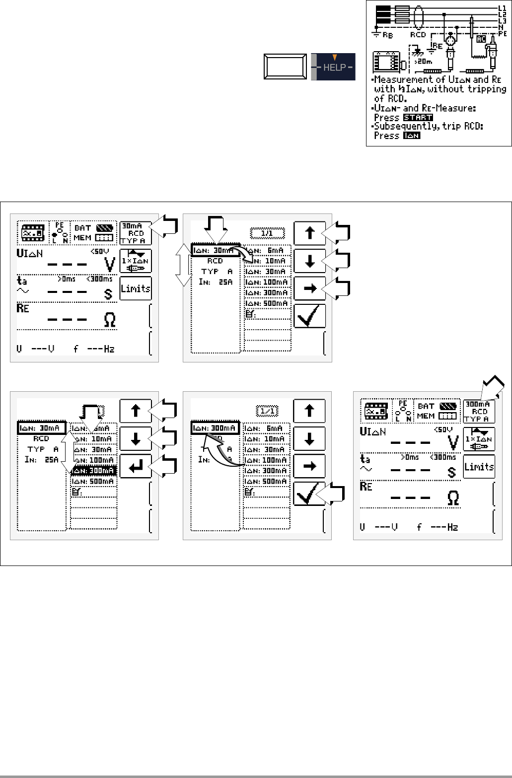
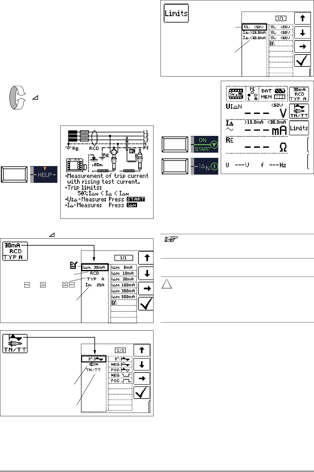
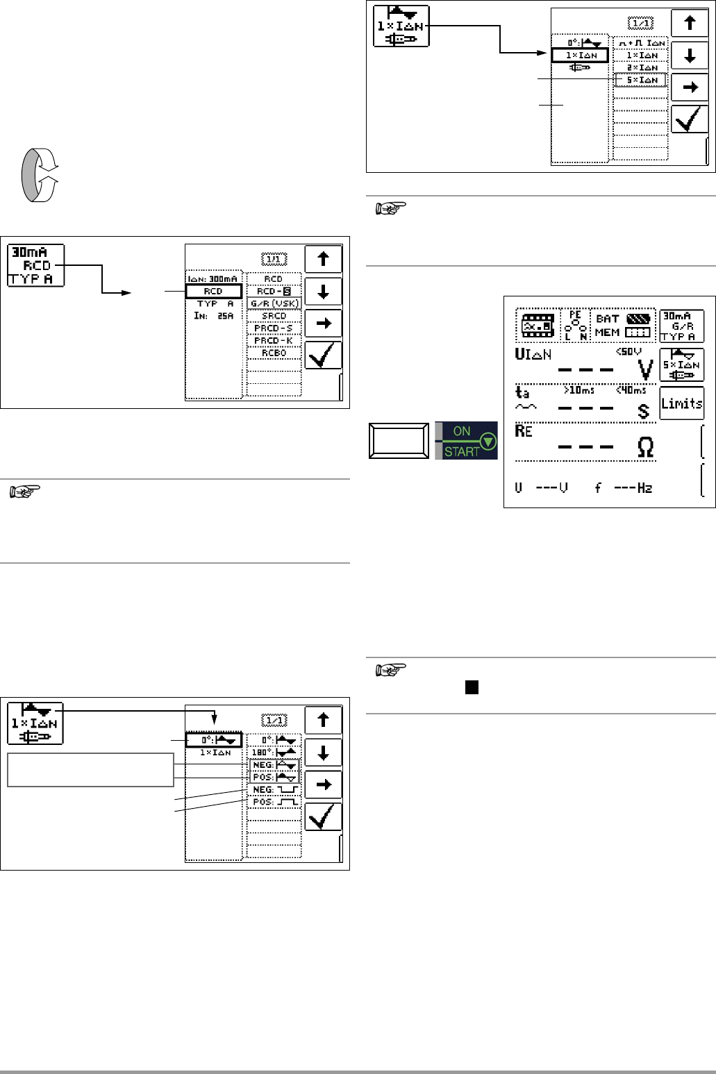
5.6 Setting Parameters or Limit Values using RCD Measurement as an
Example .....................................................................................14
5.7 Freely Selectable Parameter Settings or Limit Values ..............
5.8 2-Pole Mea ... 15
6 Measuring Voltage and Frequency ................................ 16
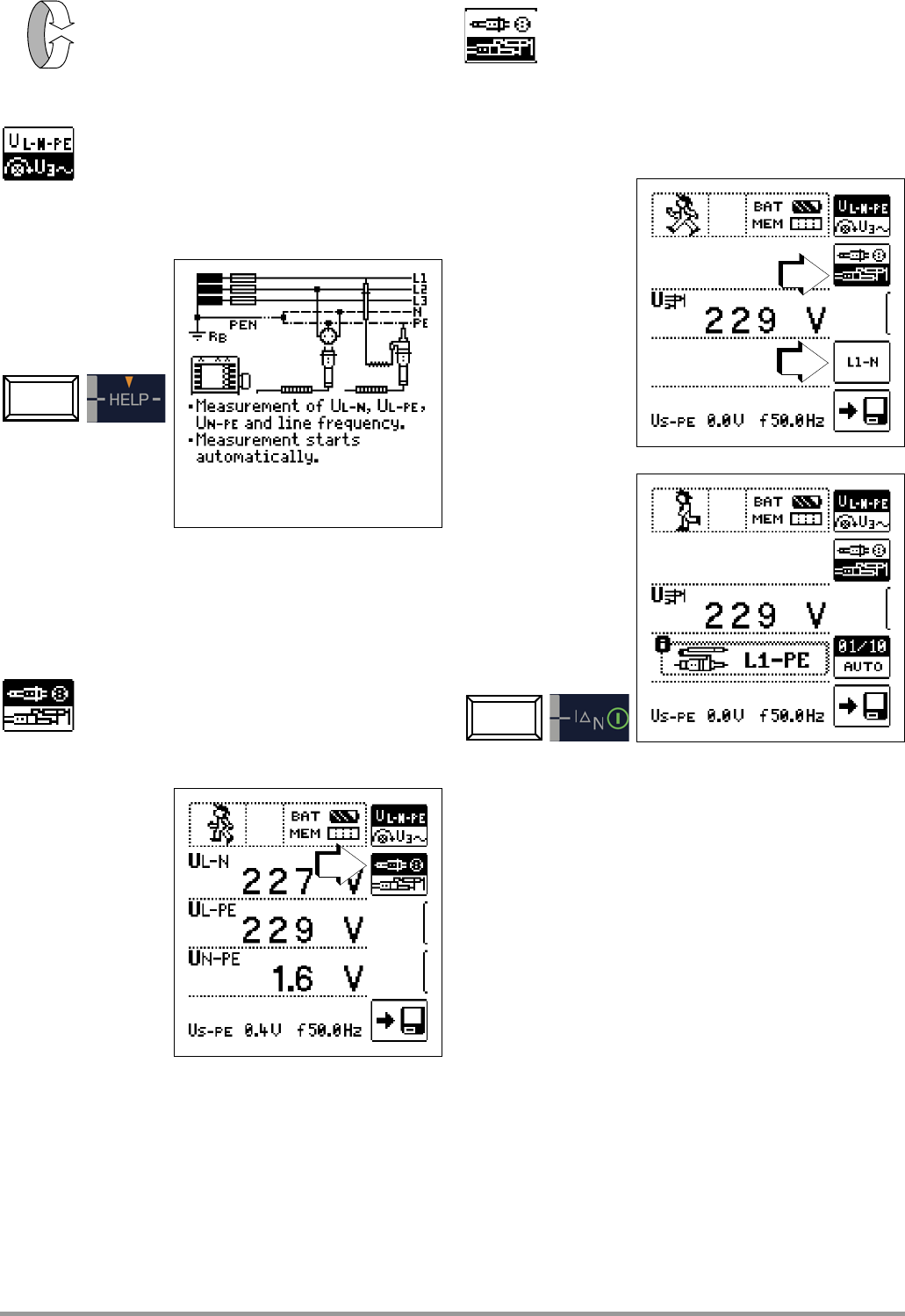
6.1 Single-Phase Measurement ......................................................16
6.1.1 Voltage Between L and N (U
L-
),
L and PE
(U
L-
) a
nd N and PE
(U
N-PE
)
with Country-Specific Plug Insert, e
6.1.2 Voltage between L – PE, N – PE L – L with 2-Pole Adapter Connection
6.2 3-Phase Measurement (line-to-line voltage) and Phase Sequence
7
Testing RCDs ..............................................
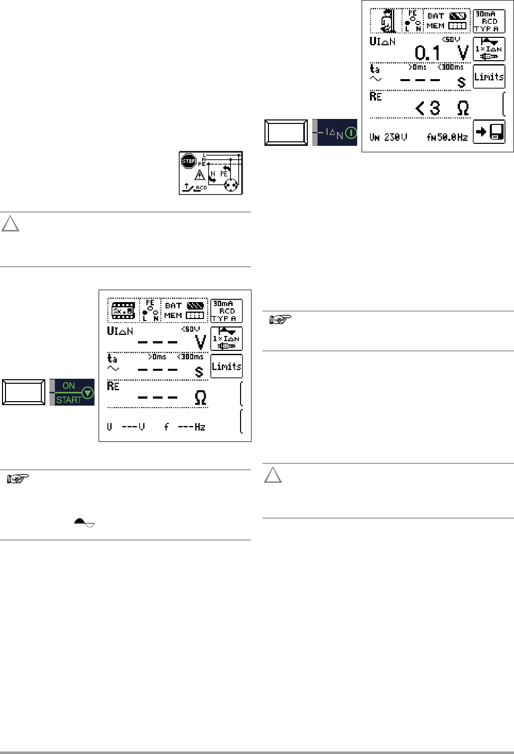
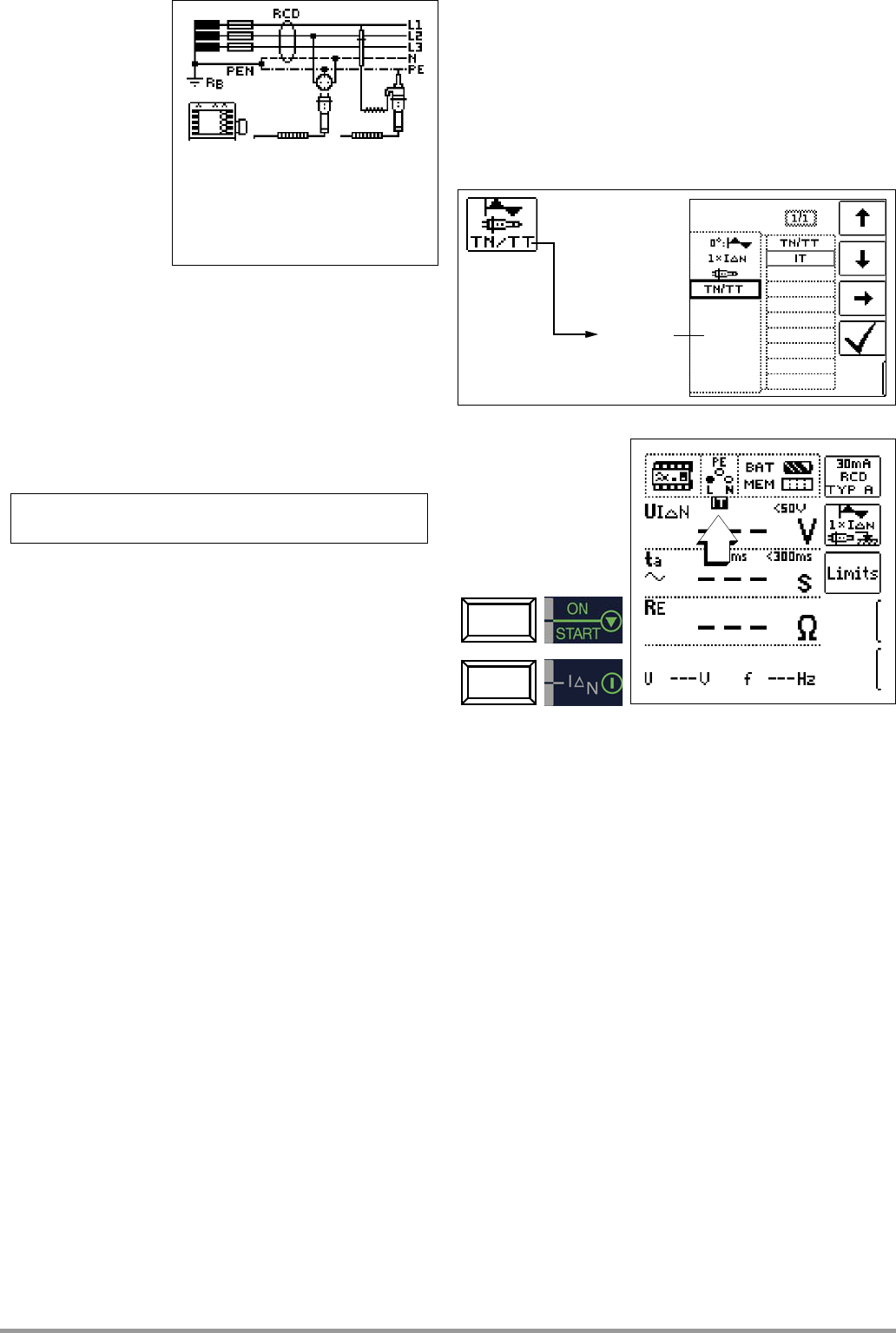
7.1 Measuring Contact Voltage (with reference to nominal residual
current) with
1
/
3
Nominal Residual Current and Tripping Test with
Nominal Residual Current .........................................................18
7.2
Special Testing fo
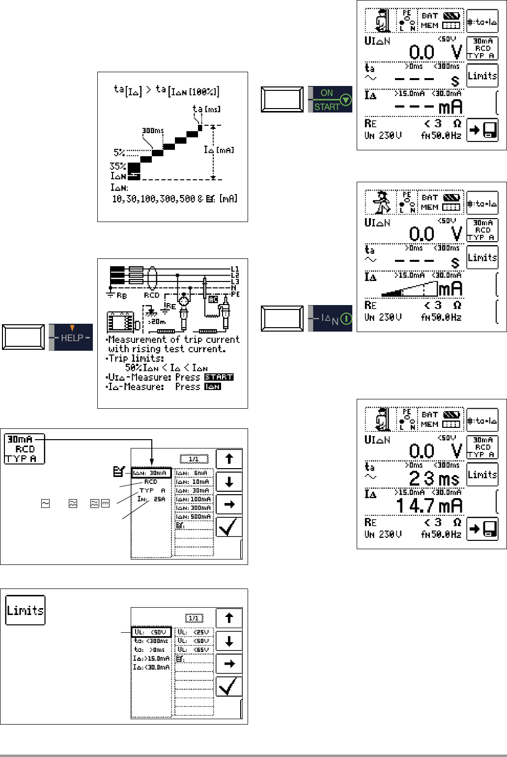
7.2.1 Testing Systems and RCCBs with Rising Residual (A
AC, A/F, B/B+ and EV RCDs
7.2.2 Testing Systems and RCCBs with Rising Residual (A
B/B+ and EV RCDs (nur MTECH+, MXTRA & SECULIFE IP ) ............20
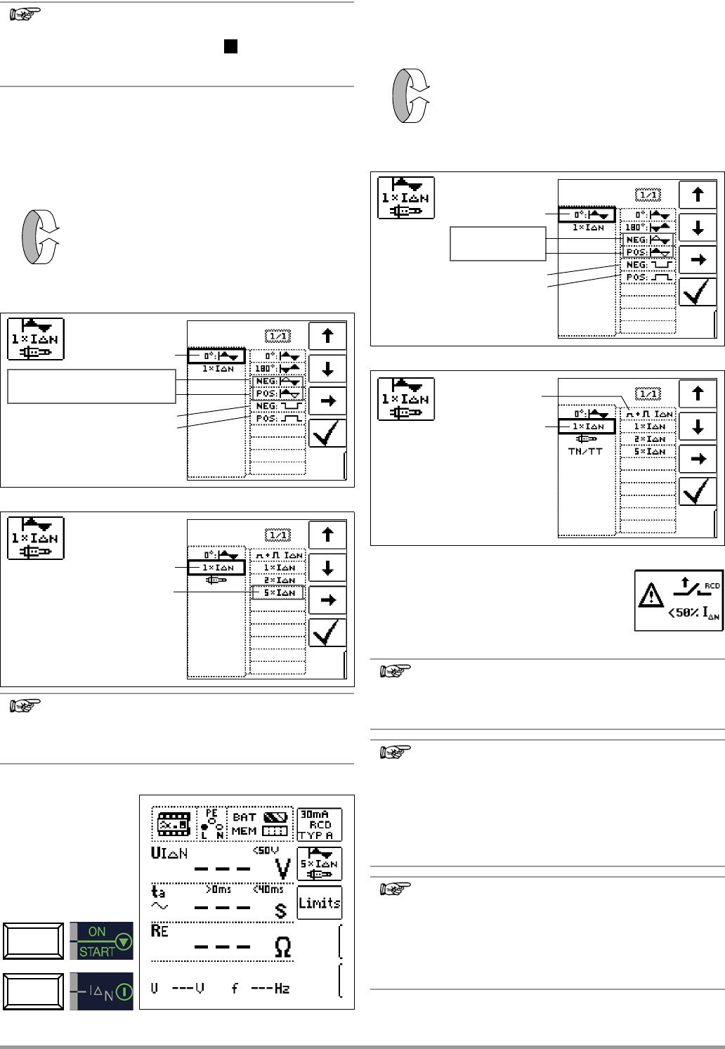
7.2.3 Testing RCCBS with 5 I
N ..............
7.2.4 Testing of RCCBs which are Suited for
Pulsating DC Residual Current
7.3 Testing for Special RCDs
7.3.1 System, Type RCD-S Selective RCCBs ..........................................
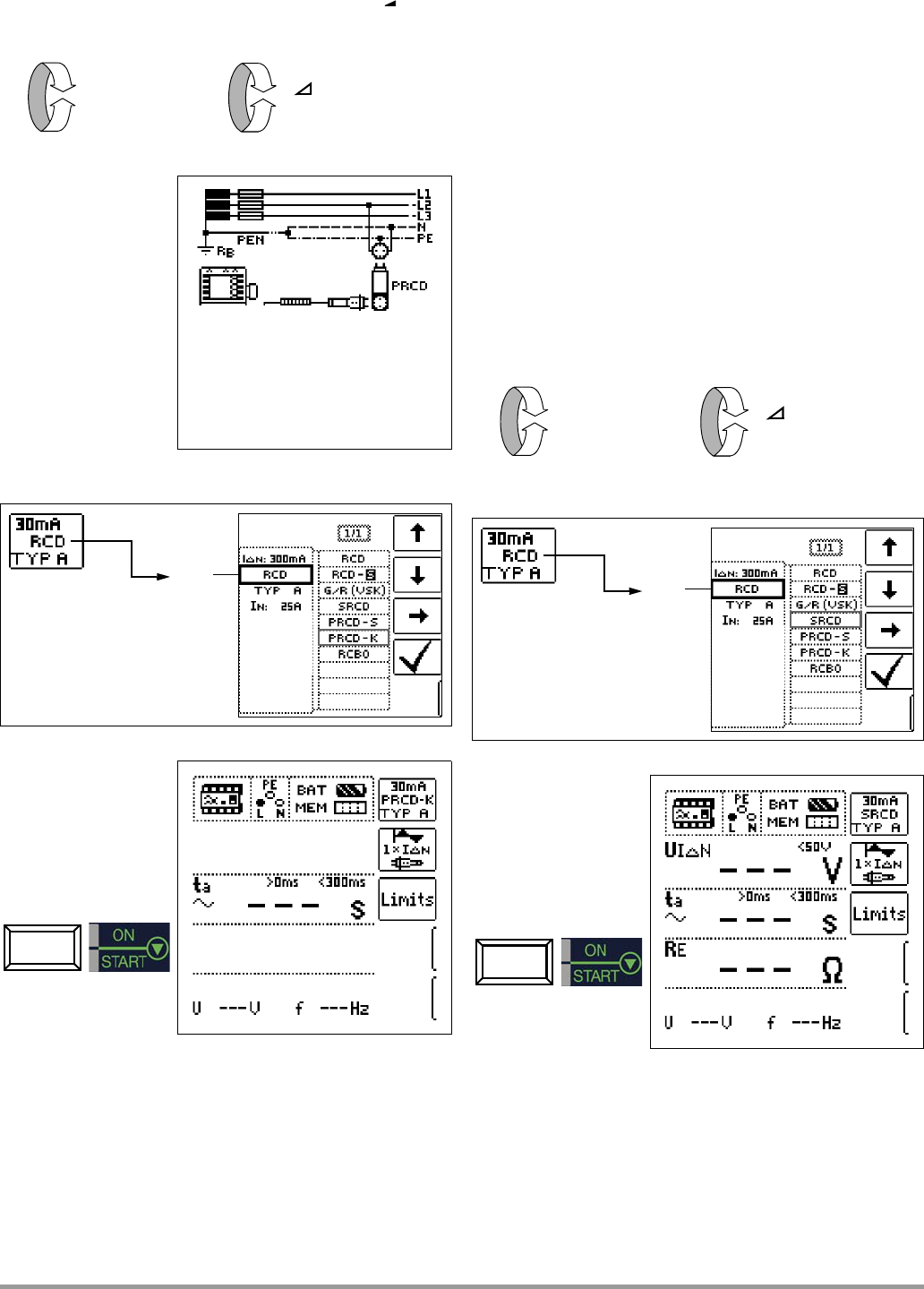
7.3.2 PRCDs with Non-Linear Type PRCD-K Elements ............................
7.3.3 SRCD, PRCD-S (S
7.3.4 Type G or R RCCB .................................
7.4 Testing Residual Current Circuit Breakers in TN-S Systems
7.5 Testing of RCD Protection in IT Systems with Hi
Capacitance (e.g. in Norway) ..................................
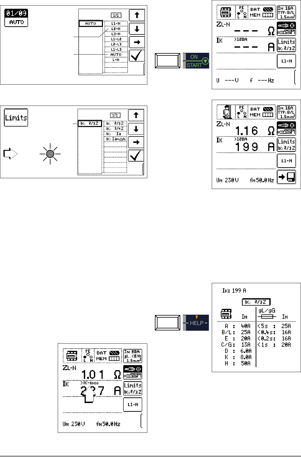
8 Testing of Breaking Requirements
Overcurrent Protective Devices,
Measurement of Loop Impedance and
Determination of Short-Circuit Current
(functions Z
L-
and I
K
) ................................................. 26
8.1 Measurements with Suppression of RCD Tripping
8.1.1 Measurement with Positive Half-Waves (only MTECH+/MXTRA/
SECULIFE IP) ...............................................................................27
8.2 Evaluation of Measured Values .................................................
8.3
Settings
K
........28
9 Measuring Line Impedance (Z
L-
function) ................... 28
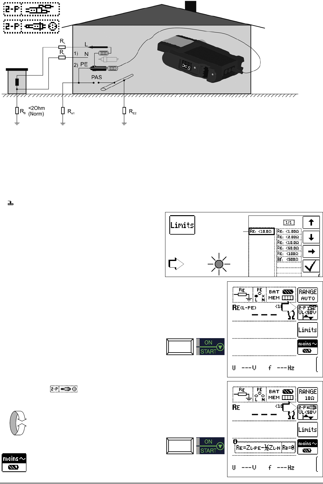
10 Earthing Resistance Measurement (R
E
function)
10.1 Earthing Resistance Measurement – Mains Operated
10.2 Earthing Resistance Meas
(only MPRO & MXTRA)
10.3 Earthing Resi
Pole Adapter or Country-Specific Plug (Schuko) without Probe ... 32
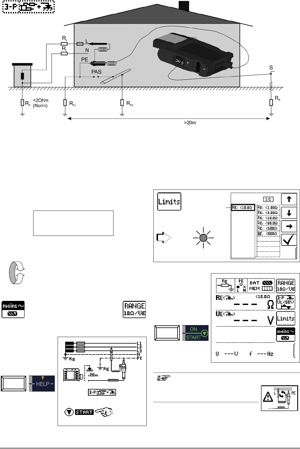
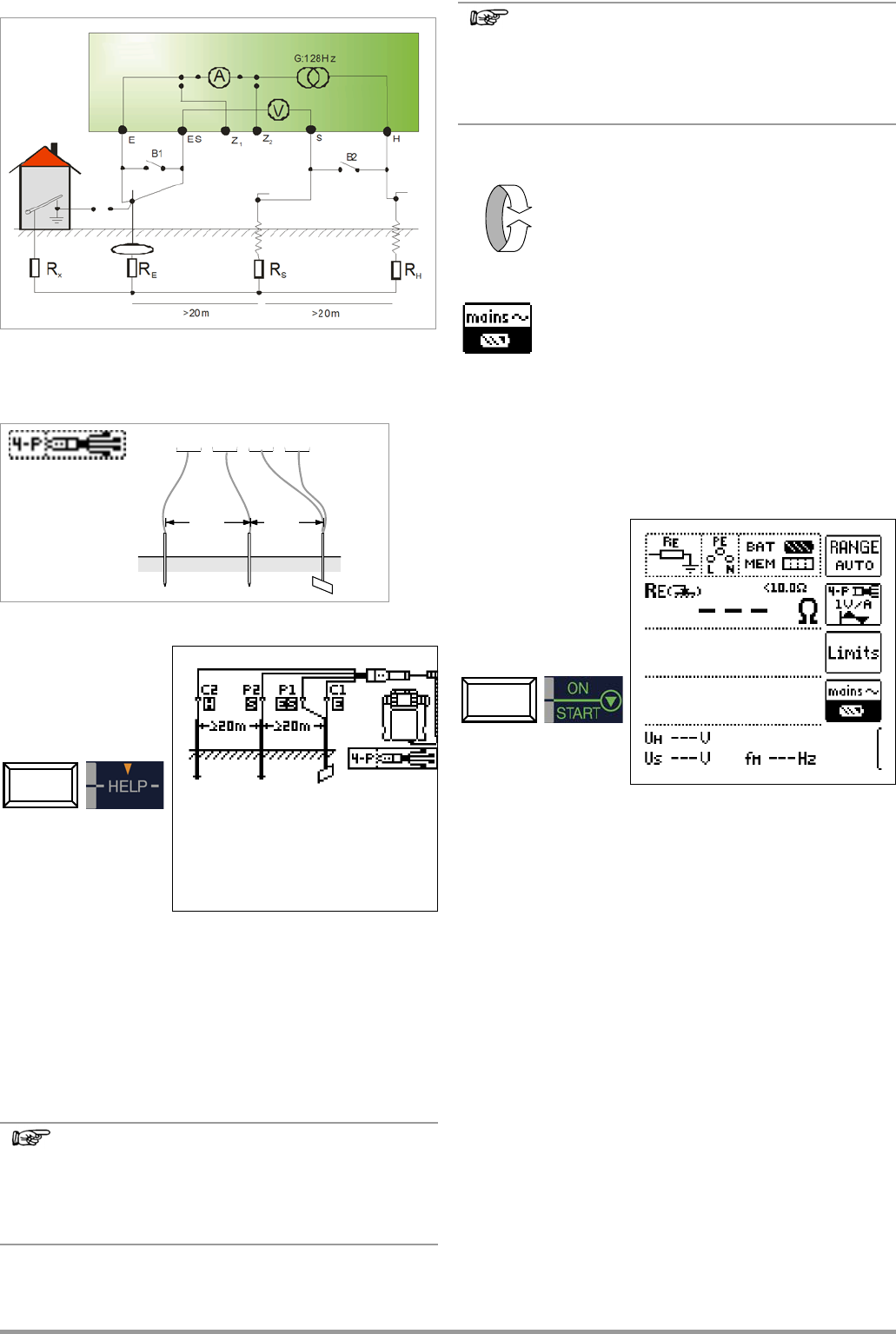
10.4 Earthing Resistance Measurement, Mains Powered – 3-Pole Me-
asurement: 2-Pole Adapter with Probe
10.5 Earthing Resistance Measurem
rement of Earth Electrode Voltage (U
E
function)
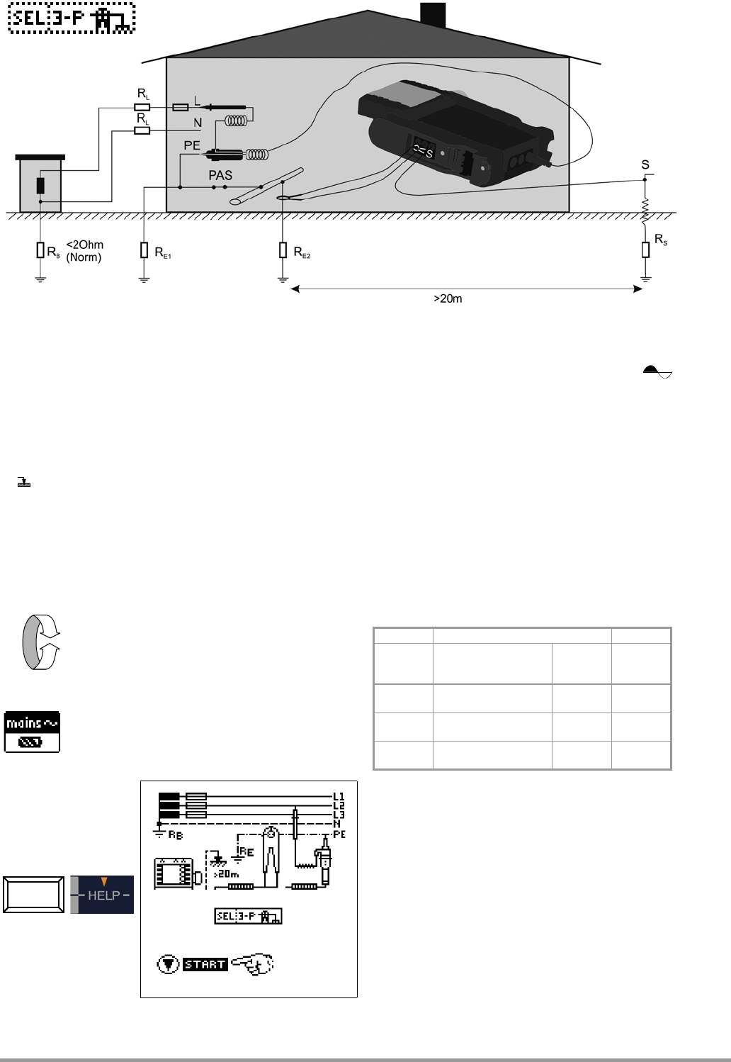
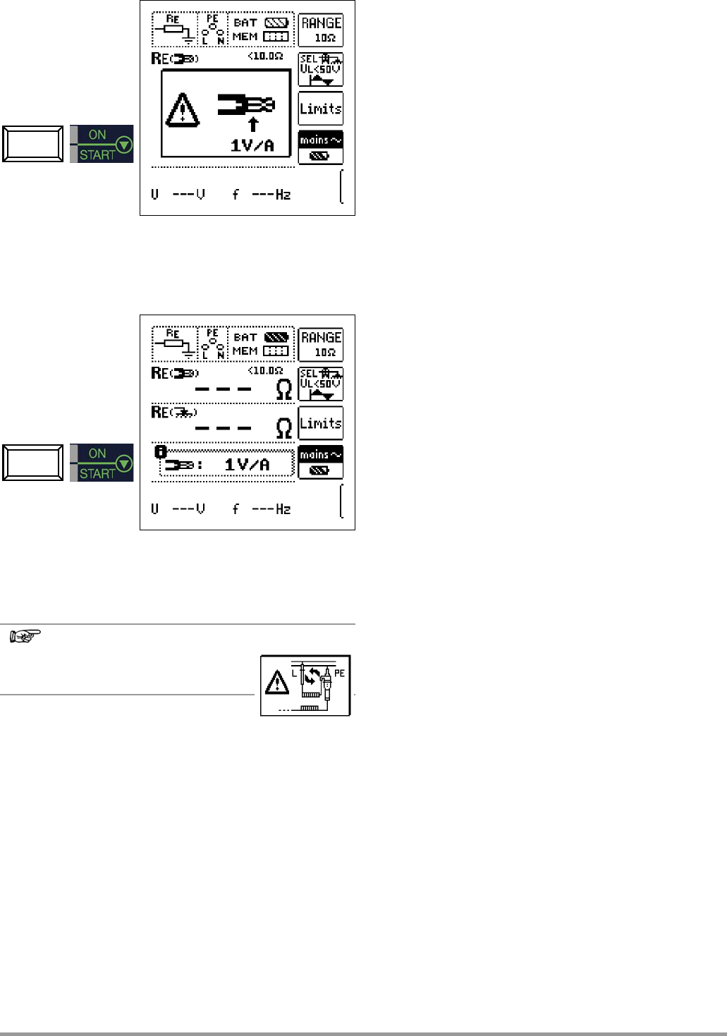
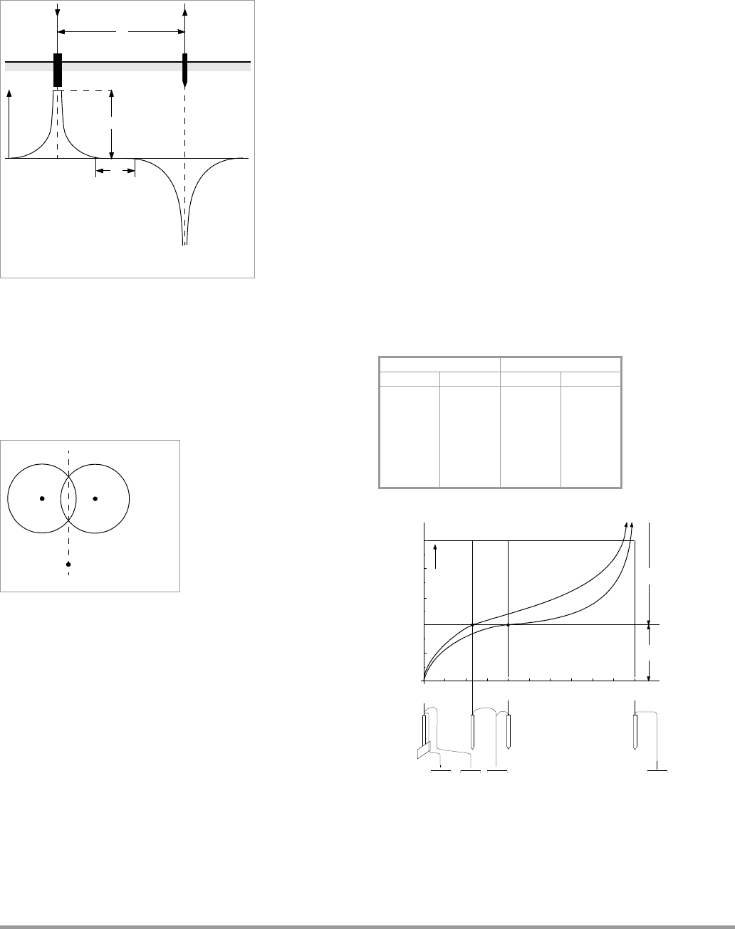
10.6 Earthing Resistance Measurement, Mains Powered – Selective
Earthing Resistance Measurement with Current Clamp Sensor as
Accessory ............................................
10.7 Earthing Resistance Measuremen
(only MPRO & MXTRA)
10.8 Earthing Resistance Measuremen
(only MPRO & MXTRA)
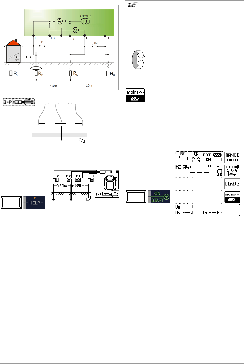
10.9 Earthing Resistance Measurement,
(4-pole) with Current Clamp Sensor and PRO-RE Measuring Adap-
ter as Accessory (only MPRO & MXTRA) ...................................
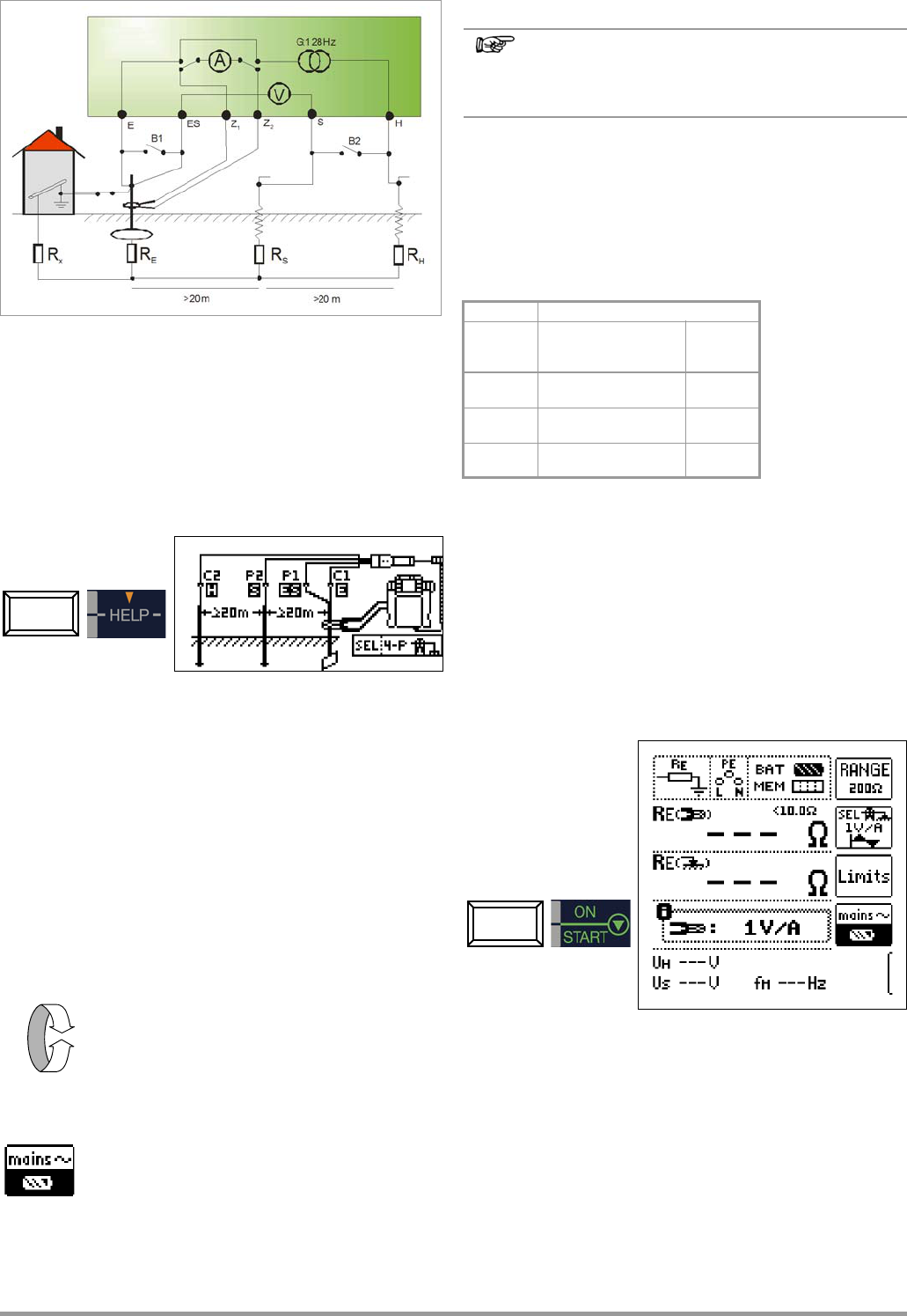
10.10 Earthing Resistance Measurement, Battery Powered – Ground Loop
Measurement (with current clamp sensor and transformer, plus PRO-
RE/2 measur ..... 41
10.11 Earthing Resistance Measurement, Battery Powered
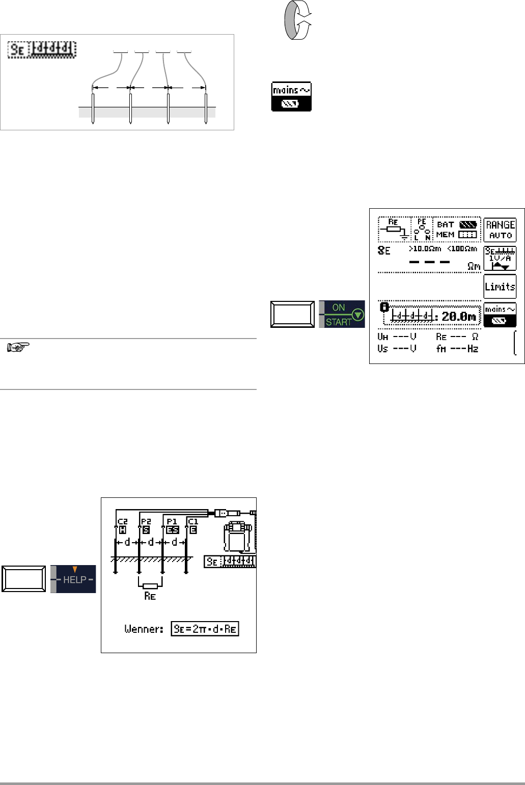
– Measurement of Soil Resistivity
E
(only MPRO & MXTRA) ...
11
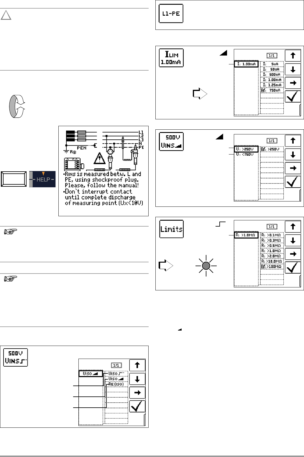
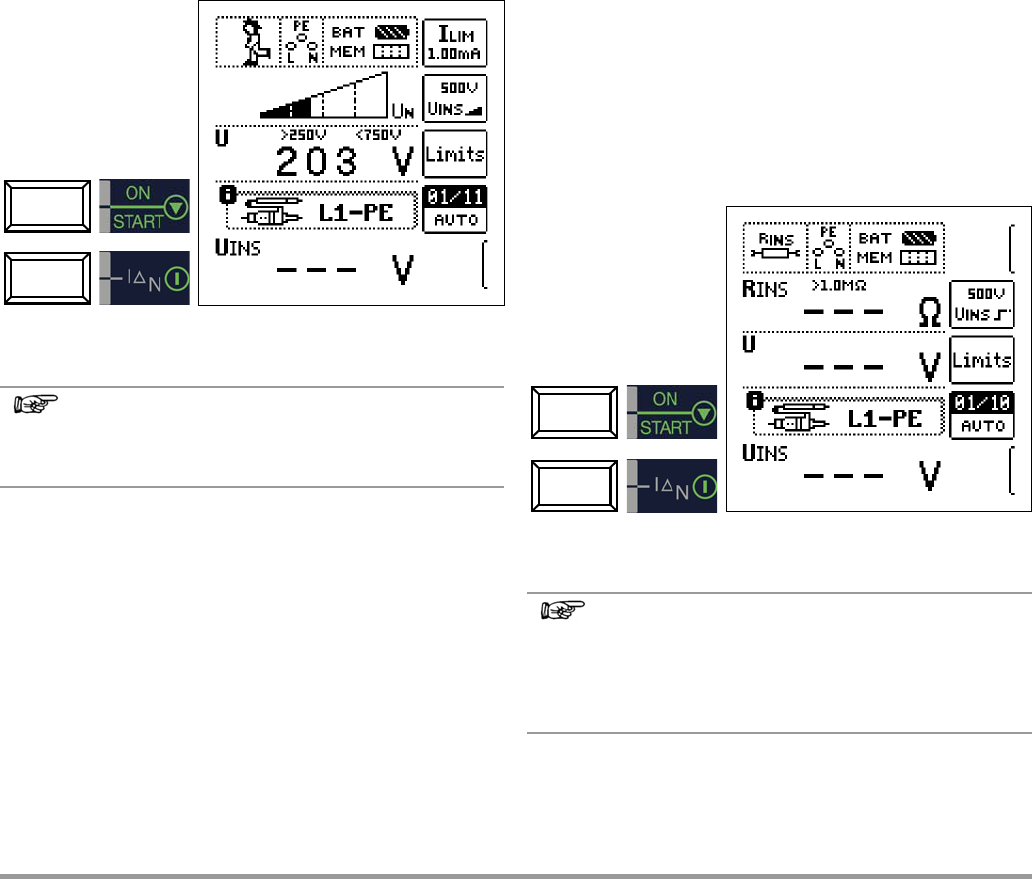
Measuring Insulation Resistance
11.1 General ............................
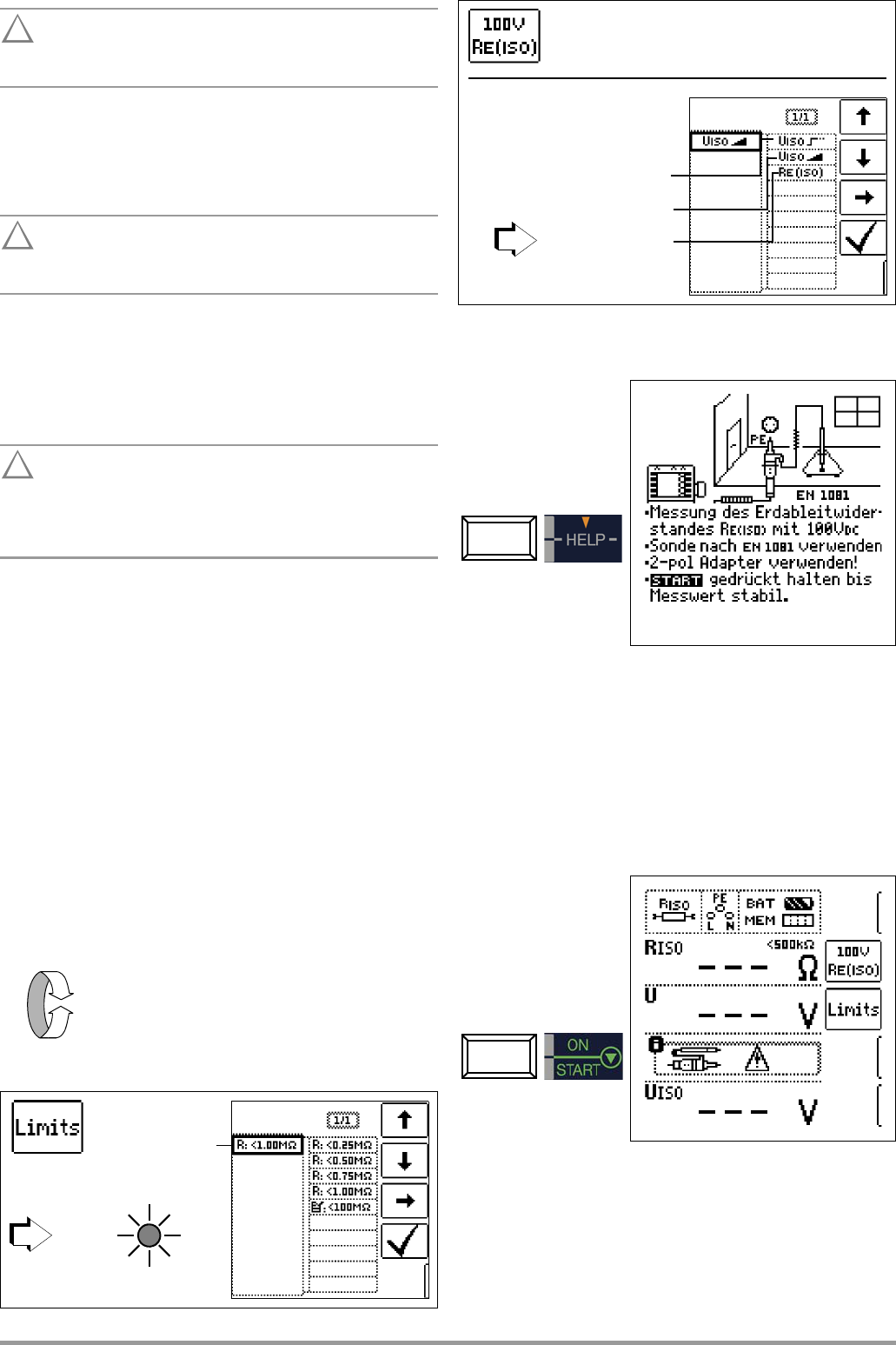
11.2 Special Case: Earth Leakage Res
EISO
) .....................
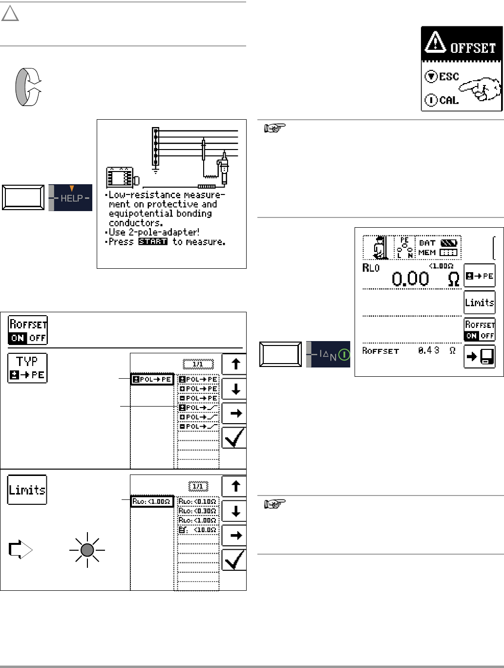
12 Measuring Low-Value Resistance
up to 200 Ohm
(protective
conductor and equipotential bonding conductor) ............... 47
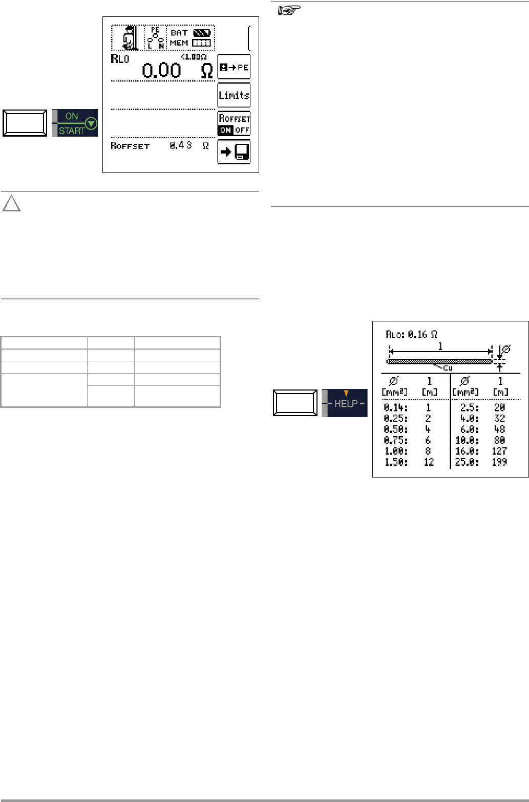
12.1 Measurements with Constant Test C
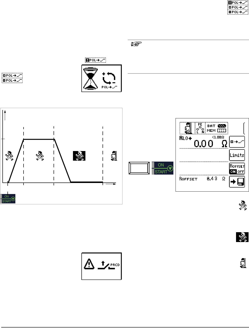
12.2 Protective Conductor Resistance Measurement with Ramp Curve
– Measurements on PRCDs wiCurrent-monitored Protective
Conductor Using PROFITEST PRCD Test Adapter as Accessory 49
13 Measurement with Accessory Sensors
13.1 Current Meas ...................
14
Special Functions – EXTRA Switch
14.1 Voltage Drop Measurement (at ZLN) – U Function .................
14.2 Measuring the Impedance of Insulating Floors and Walls (standing
surface insulation impedance) – Z
ST
Function .........................
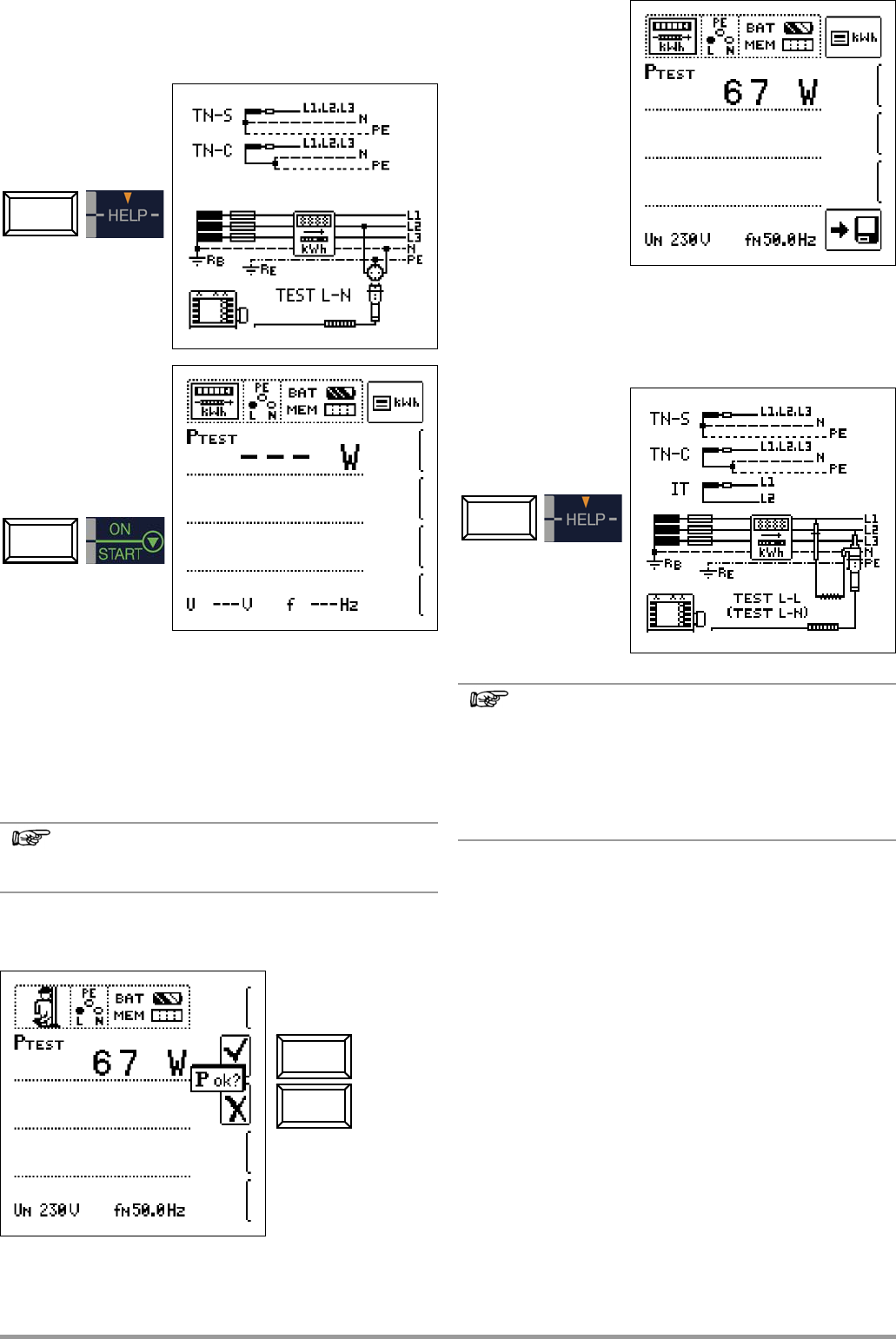
14.3 Testing Meter Start-Up with Earthing Contact Plug
– kWh Function (not SECULIFE IP) .............................................
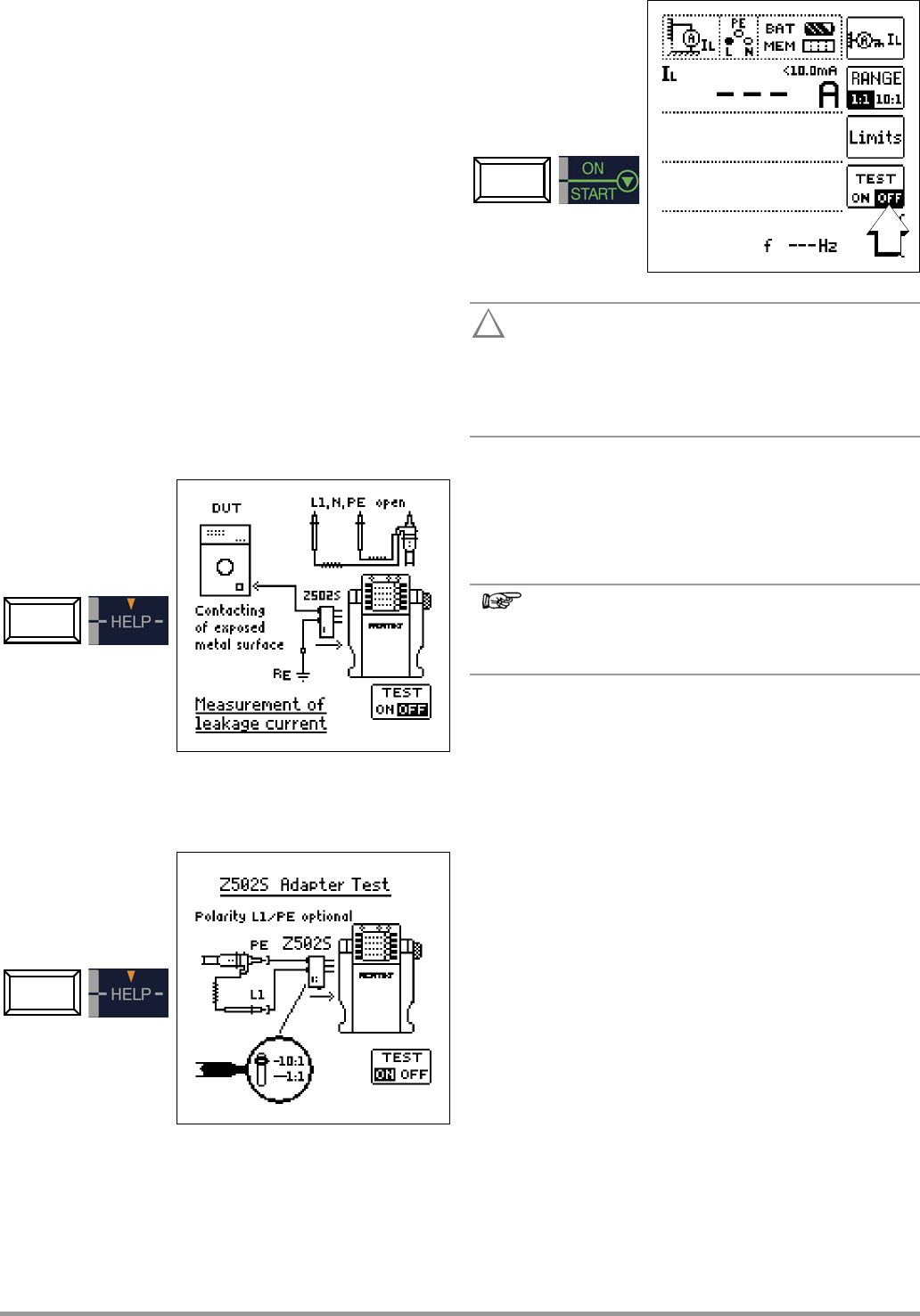
14.4 Leakage Current Measurement
with PRO-AB Leakage Current Adapter as Accessory
– I
L
Function (PROFITEST MXTRA & SECULIFE IP only) .............
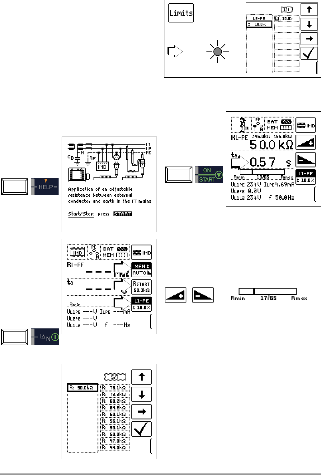
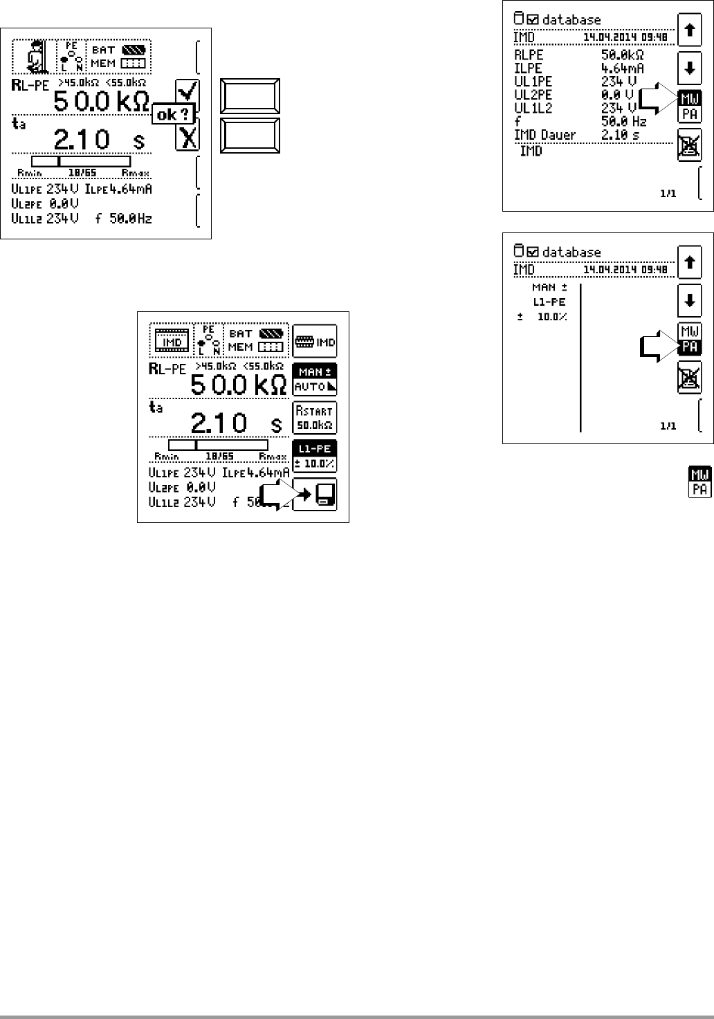
14.5 Testing of Insulation Monitoring Devices – IMD Function
(PROFITEST MXTRA & SECULIFE IP only) ...................................
14.6
Residual Voltage Tes
PROFITEST MXTRA
only)
14.7
Intelligent Ramp – ta+ID Function (
PROFITEST MXTRA
only) 59
14.7.1 Applications ..........................................
14.8 Testing Residual Current Monitors
– RCM Function (PROFITEST MXTRA only)
14.9 Testing the Operating States of Electric Vehicles at Charging Sta-
tions per IEC 61851 (MTECH+ & MXTRA only) ..........................
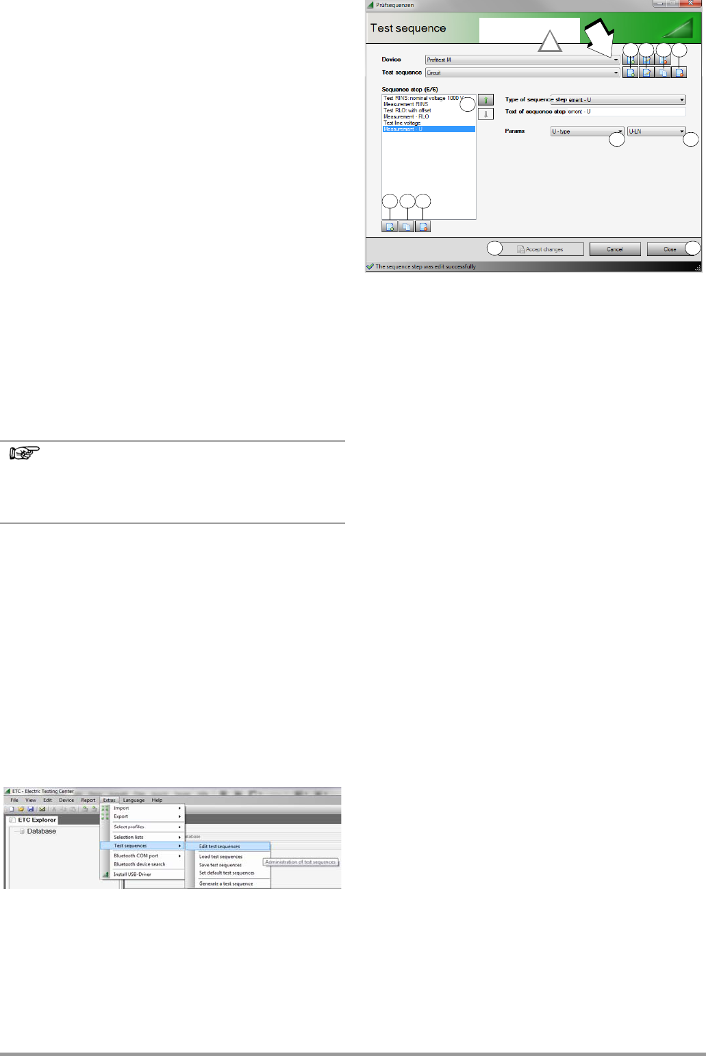
14.10 Test Sequences for Report Generation of Fault Simulations on
PRCDs with PROFITEST PRCD Adapter (MXTRA only) ...............
14.10.1 Selecting the PRCD under Test
14.10.2 Parameter Settings
14.10.3 Test Sequence PRCD-S (single phase) – 11 Test
14.10.4 Test Sequence PRCD-S (three-phase) – 18 Test Steps ..................
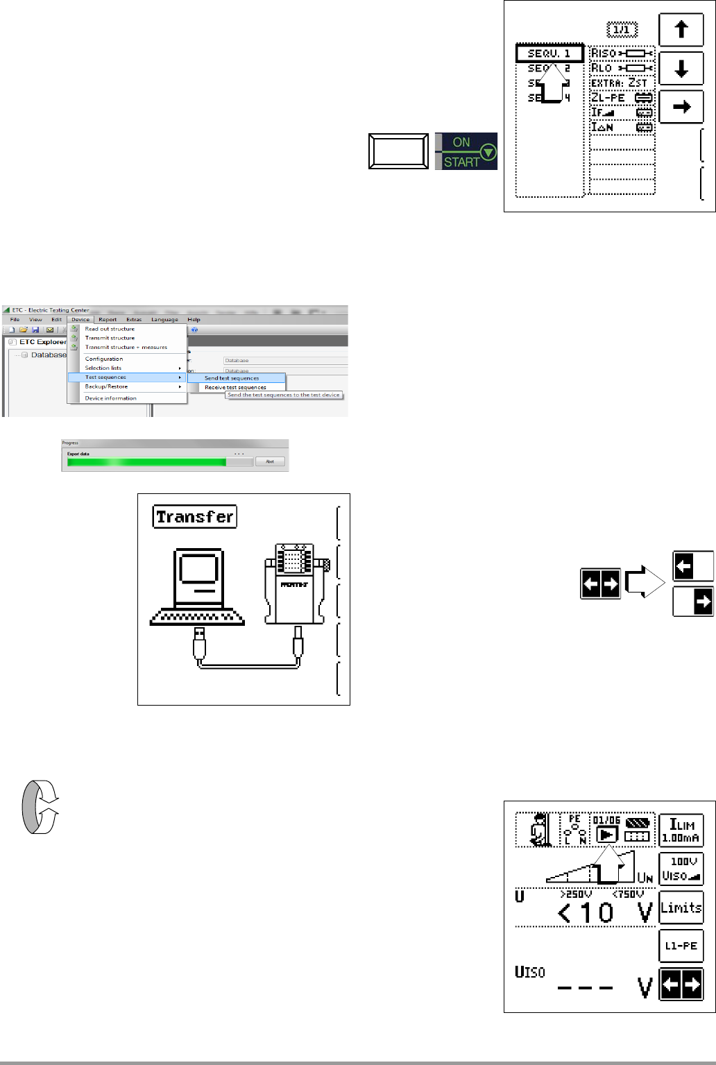
15 Automatic Test Sequences – AUTO Function 64
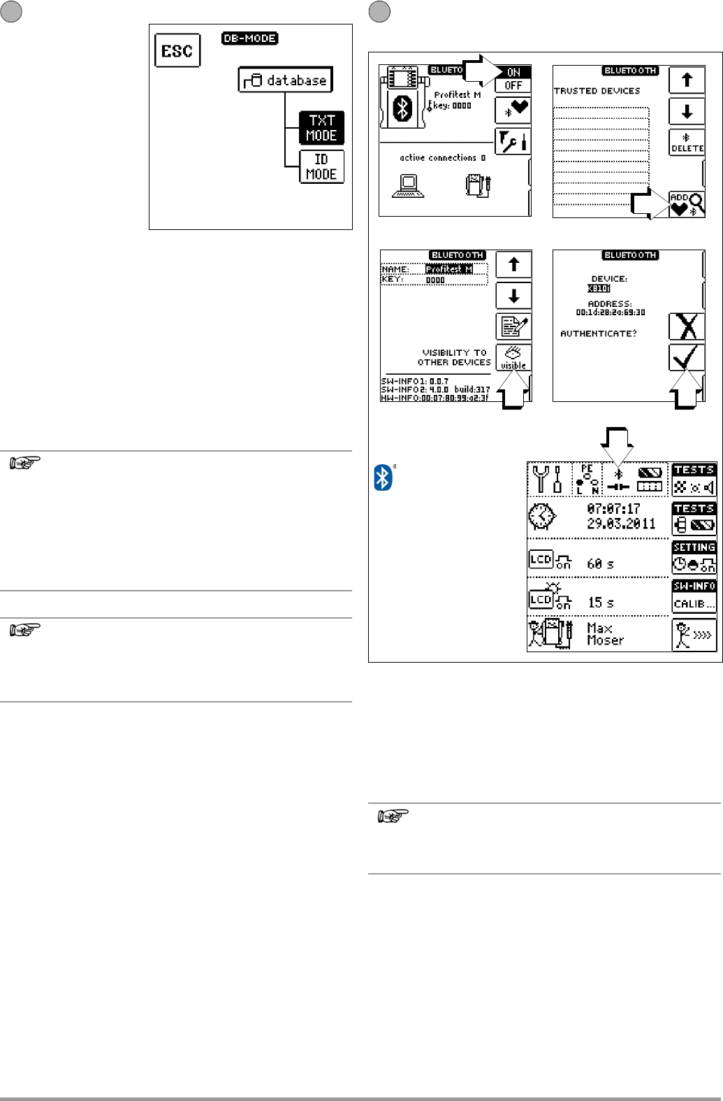
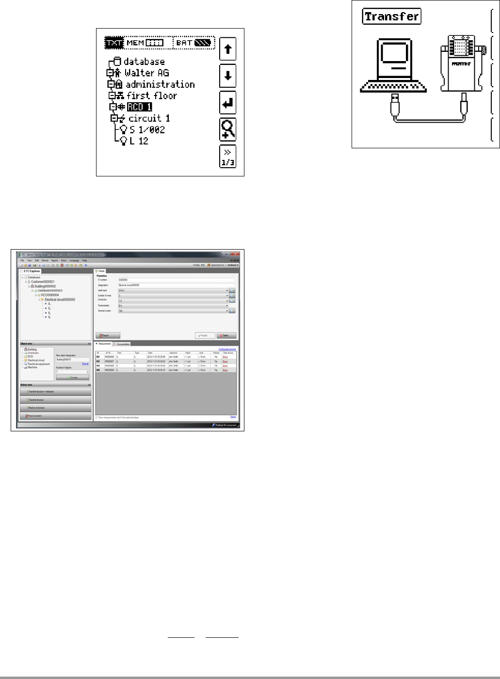
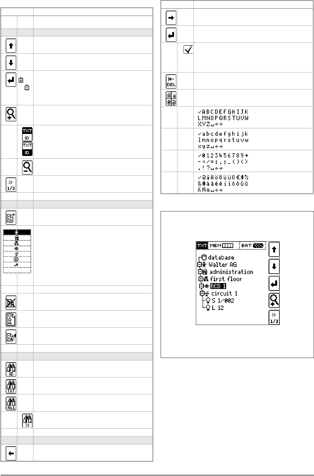
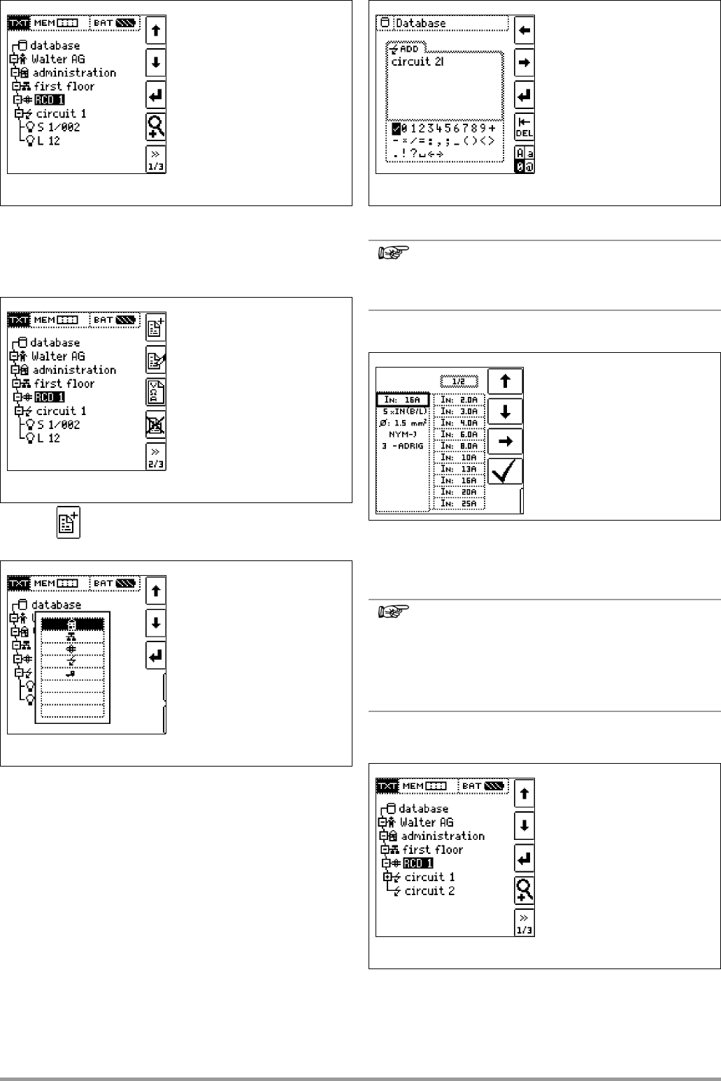
16 Database ........................................................................ 66
16.1 Creating Disructures, General