FURUNO
RD-20
SP - 1 E4454S01E
SPECIFICATIONS OF REMOTE DISPLAY
RD-20
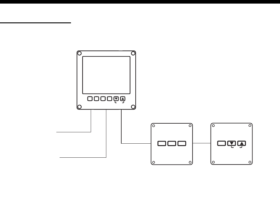
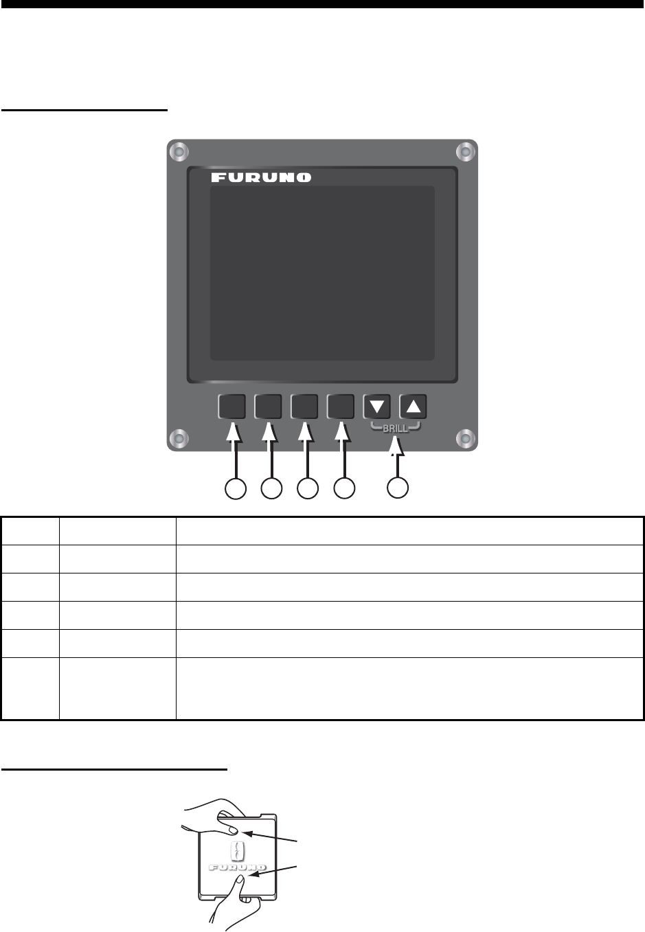
1 REMOTE DISPLAY
1.1 Display type Segment LED and dot matrix (red)
1.2 Brilliance 10 steps (includes ‘OFF’)
1.3 Data indication Ship’s speed, Course, Heading, Distance, Depth, Rate of turn,
Wind direction/speed, Rudder angle, Engine/ shaft RPM,
Propeller pitch, Water temperature
1.4 Remote control Remote controller (option) required
1.5 Remote dimmer Dimmer controller (option) required
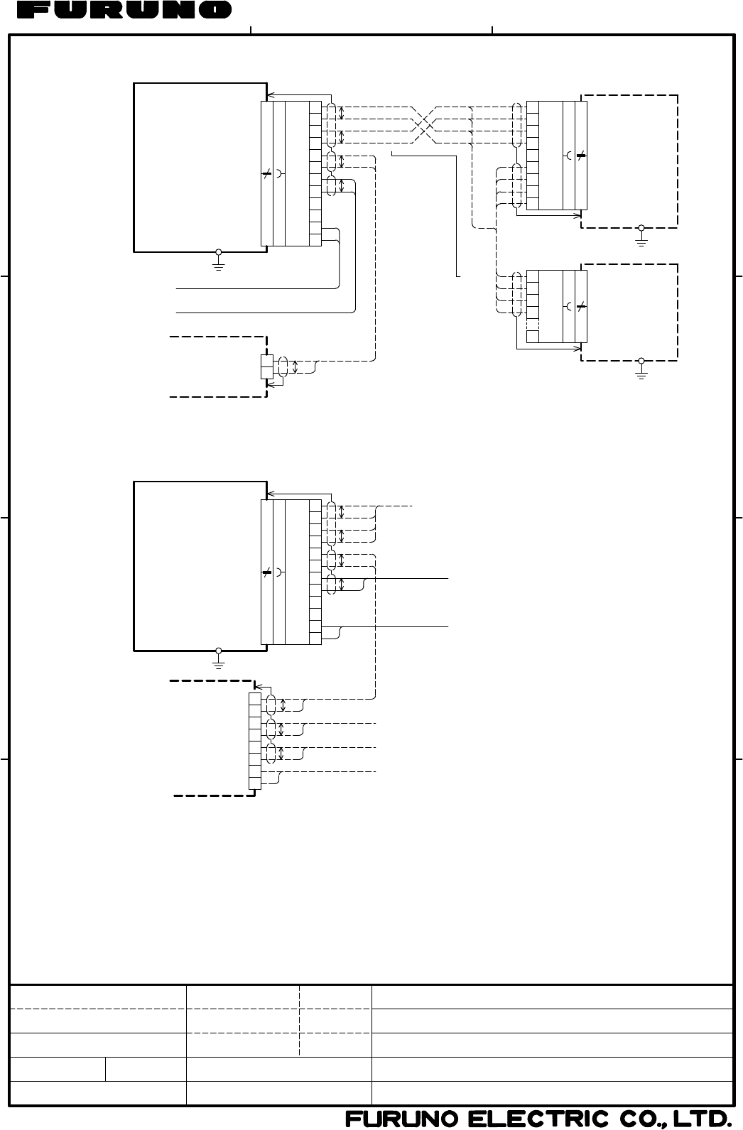
1.6 Interface
Remote control Serial, 1 port, 38,400 bps,
5 VDC output (for remote/dimmer controller)
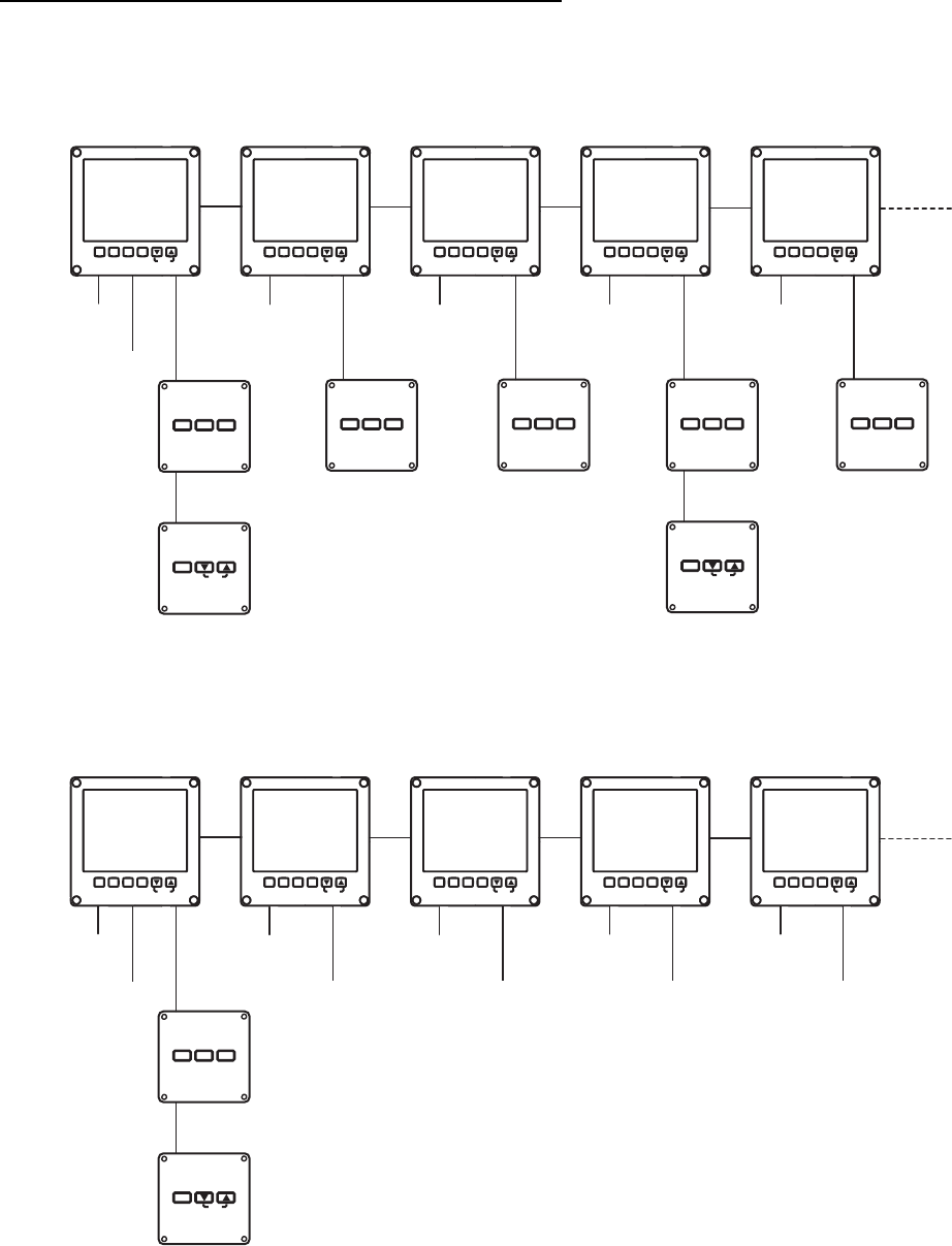
Sensor Input: 1 port, NMEA0183 Ver1.5/2.0/3.0
Daisy chain (for RD-20) Output: 1 port, 38,400 bps
1.7 Data sentences DBK, DBS, DBT, DPT, HDG, HDT, HDM, HTC, HTD, MTW, MWV,
RPM, RMC, ROT, RSA, VBW, VHW, VLW, VTG, VWT, VWR
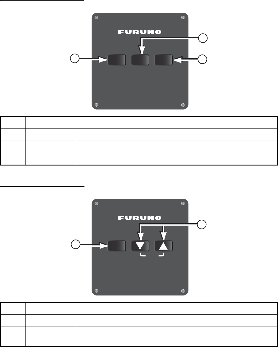
2 REMOTE CONTROLLER (OPTION)
2.1 Control button DISP, UNIT, MODE
2.2 Interface Serial, Input: 1 port, Output: 1 port, 38,400 bps
5 VDC input (supplied from remote display)
5 VDC output (for dimmer controller)
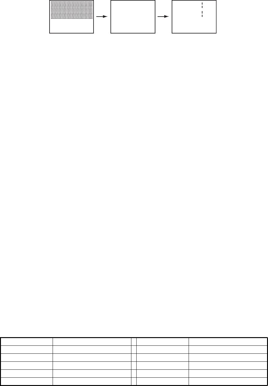
3 DIMMER CONTROLLER (OPTION)
3.1 Control button DAY/NT, BRILL (▲/▼)
3.2 Interface Serial, Output: 1 port, 38,400 bps
5 VDC input (supplied from remote display)
4 POWER SUPPLY
4.1 Remote display 12-24 VDC: 0.6-0.3 A (includes controller source)
5 ENVIRONMENTAL CONDITION
5.1 Ambient temperature
Remote display -25°C to +55°C
Remote/Dimmer controller -15°C to +55°C
5.2 Relative humidity 95% at 40°C
5.3 Degree of protection IP22, IP56 (optional waterproof box required)
5.4 Vibration IEC 60945
6 UNIT COLOR
N2.5