28 Ferm
3. Readout the value in (milli) Ampere.
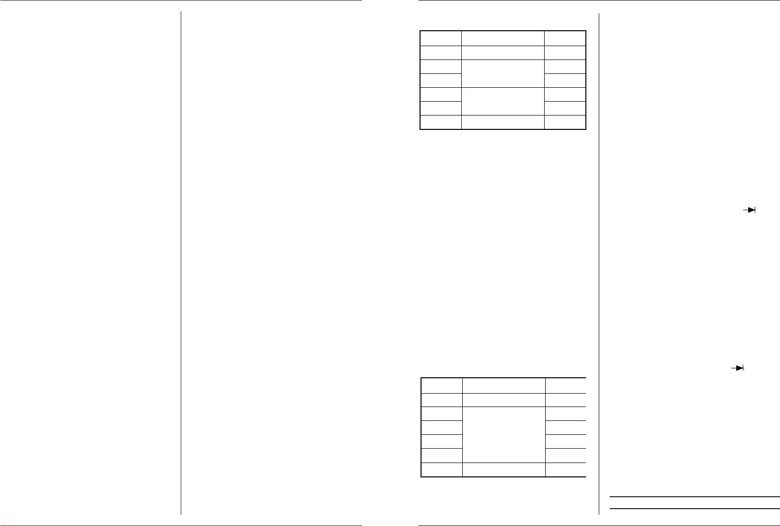
RANGE ACCURACY RESOLUT.
Overload protection: 2A/250V fuse, 20A range is not fused.
Frequecy range: 40...400 Hz.
Max. input current: 20A, 15 seconds.
Max. voltage drop: 200 mV.
Indication: Average value (rms of sine shape).
NB:
1. In case you do not know the current range, set the
FUNCTION-switch to the highest range and turn
it down gradually, if necessary.
2. Set the FUNCTION-switch to a higher range,
when only the figure “1” is displayed. In this case,
the value is out of range.
3. The 20A range is not protected with a fuse.
Never measure for more than 15 seconds.
11.5 Measuring resistance (Ω OHM)
1. Put the BLACK cord on the “COM” connector
and the RED one on “V/Ω”. (NB. The polarity of
the red cord is “+”).
2. Set the FUNCTION knob to the desired “Ω”-range.
3. Connect the measuring pins to the respective
component. Take care that the component is not
connected to other components and do not touch
the points of the measuring pins, in order to pre-
vent inaccuracy of the resistance value.
4. Readout the value in Ω (Ohm)
RANGE ACCURACY RESOLUT.
Overload security: 250 VDC or AC. If less than 15 seconds.
Voltage open circuit: below 700 mV
5. Current from the internal battery will be used, for
the measurement of resistance’s. The electricity
consumption will vary with the range you have set.
NB:
1. “1” will be shown on the display, in case the meas-
ured resistance value exceeds the maximum value
of the selected range. Select a higher range. It can
take a few seconds for the meter to stabilize with a
resistance of about 1 MΩ or higher. This is normal
when measuring high resistance’s.
2. If the input is not connected, e.g. for an interrupted
circuit, the figure “1”will be shown on the display,
to indicate that the value is out of range.
3. In case the respective resistance is connected
to a circuit: Switch off the voltage and take
care that every condensator has been fully dis-
charged, before starting the measurement.
11.6 Measuring diodes
1 Connect the BLACK cord to the “COM”-con-
nector and the RED one to the “V/Ω”-connec-
tor. (NB. The polarity of the red cord is “+”)
2. Set the FUNCTION-switch to the -range
and connect the measuring pins to the respective
diode. When measuring, the polarity of the measu-
ring pins will determine whether the diodes or
transistors are measured in the forward or reverse
direction. The test current in forward direction will
be 1 mA, the test voltage in reverse direction will
be 2.8 V. Overload protection: 250 VDC or AC
(less than 15 seconds). The value on the display will
be the voltage over the diode in forward direction.
- ”1” will be shown on the display, when the
measuring cords are not or wrongly (= in
reverse direction) connected to the diode.
11.7 Continuity test
1. Put the BLACK cord to the “COM”-connector
and the RED one to the “V/Ω” (NB. The polarity
of the red cord is “+”)
2. Set the FUNCTION-switch to the -range and
connect the measuring pins to the respective circuit.
3. In case the resistance is less than 30Ω, the buzzer
will sound.
4. Open circuit voltage: 2.8 V, overload protection:
250 VDC or AC (less than 15 seconds)
11.8 hFE transistor measurement
1. Set the switch in the “hFE” position
2. Determine the type of the transistor (NPN or PNP)
and connect the emitter-, base- and collector cords
to the correct opening in the panel on the front.
3. The display will show the approximate hFE-value,
at a base current of 10 µA, Vce 2.8 V.
12. MAINTENANCE
NOTE: Always remove the battery from your multi-