About this Manual ..........................................................................................................................................................................................9
Technical Support ........................................................................................................................................................................................10
Datalogic Website Support ...............................................................................................................................................................................................................10
Reseller Technical Support ................................................................................................................................................................................................................10
Telephone Technical Support ..........................................................................................................................................................................................................10
About the Reader .........................................................................................................................................................................................11
The BC40xx™ Radio Base .............................................................................................................................................................................12
Base LEDs .................................................................................................................................................................................................................................................12
Base Button .............................................................................................................................................................................................................................................12
Programming the Reader ............................................................................................................................................................................16
Setting Up the Reader ..................................................................................................................................................................................17
Installing the Interface Cable ......................................................................................................................................................................18
Configuring the Base Station ......................................................................................................................................................................20
Changing the Base Station Position ..............................................................................................................................................................................................21
Connecting the Base Station ............................................................................................................................................................................................................22
Connecting the Base when Security Pin is Enabled .................................................................................................................................................................25
Linking the Reader to a Base Station .............................................................................................................................................................................................25
Linking a BT Reader to a PC ..............................................................................................................................................................................................................26
Gryphon™ 2D System and Network Layouts ..............................................................................................................................................27
Stand Alone Layouts ...........................................................................................................................................................................................................................27
Setting the Interface ............................................................................................................................................................................................................................29
Global Interface Features ...................................................................................................................................................................................................................33
Configuring Other Features ..............................................................................................................................................................................................................33
Software Version Transmission .......................................................................................................................................................................................................33
Resetting the Product Configuration to Defaults .....................................................................................................................................................................34
Replacing the Battery ..........................................................................................................................................................................................................................35
CONFIGURATION USING BAR CODES............................................................................................................................................ 37
GLOBAL INTERFACE FEATURES ..................................................................................................................................................39
USB Suspend Mode ........................................................................................................................................................................................................39
Data Bits .............................................................................................................................................................................................................................43
Handshaking Control ....................................................................................................................................................................................................45
Beep On ASCII BEL ..........................................................................................................................................................................................................47
Beep On Not on File .......................................................................................................................................................................................................48
ACK Character ..................................................................................................................................................................................................................50
NAK Character ..................................................................................................................................................................................................................50
ACK NAK Timeout Value ...............................................................................................................................................................................................51
Disable Character ............................................................................................................................................................................................................53
Enable Character .............................................................................................................................................................................................................53
Country Mode ..................................................................................................................................................................................................................56
Send Control Characters ..............................................................................................................................................................................................60
Caps Lock State ................................................................................................................................................................................................................62
USB Keyboard Speed .....................................................................................................................................................................................................62
USB Keyboard Numeric Keypad ................................................................................................................................................................................64
IBM 46XX Interface................................................................................................................................................................. 67
46xx Number of Host Resets .......................................................................................................................................................................................68
Transmit Labels in Code 39 Format ..........................................................................................................................................................................70
Wand Signal Speed ........................................................................................................................................................................................................72
Wand Idle State ................................................................................................................................................................................................................73
Data Format ............................................................................................................................................................................ 75
Global Prefix/Suffix ......................................................................................................................................................................................76
Global AIM ID ................................................................................................................................................................................................77
Set AIM ID Individually for GS1-128 ...............................................................................................................................................................................................79
Label ID ..........................................................................................................................................................................................................80
Individually Set Label ID .....................................................................................................................................................................................................................81
Label ID Control ...............................................................................................................................................................................................................81
Label ID Symbology Selection − 1D Symbologies ..............................................................................................................................................82
Advanced Formatting: User Label Edit ...................................................................................................................................................................87
Case Conversion ..............................................................................................................................................................................................................87
Character Conversion ....................................................................................................................................................................................................88
LED AND BEEPER INDICATORS ...................................................................................................................................................92
Power On Alert .................................................................................................................................................................................................................92
Good Read: When to Indicate .....................................................................................................................................................................................92
Good Read Beep Type ...................................................................................................................................................................................................93
Good Read Beep Frequency .......................................................................................................................................................................................93
Good Read Beep Length ..............................................................................................................................................................................................94
Good Read Beep Volume .............................................................................................................................................................................................95
Good Read LED Duration .............................................................................................................................................................................................96
SCANNING FEATURES .................................................................................................................................................................97
Stand Mode Indication ..................................................................................................................................................................................................98
Stand Operation ..............................................................................................................................................................................................................99
Stand Mode Sensitivity ..............................................................................................................................................................................................100
Stand Mode Illumination Off Time ........................................................................................................................................................................101
Scanning Active Time .................................................................................................................................................................................................101
Stand Illumination Control .......................................................................................................................................................................................102
Contents
Product Reference Guide
3
Motion Still Timeout ...................................................................................................................................................................................................102
Flash On Time ................................................................................................................................................................................................................103
Flash Off Time ................................................................................................................................................................................................................103
Green Spot Duration ...................................................................................................................................................................................................105
Mobile Phone Mode ...................................................................................................................................................................................................105
Partial Label Reading Control ..................................................................................................................................................................................106
CORDED ONLY FEATURES .........................................................................................................................................................107
Corded Stand Mode ....................................................................................................................................................................................................107
Corded Stand Beep .....................................................................................................................................................................................................108
Multiple Labels per Frame ........................................................................................................................................................................................108
Multiple Labels Ordering by Code Symbology .................................................................................................................................................109
Multiple Labels Ordering by Code Length .........................................................................................................................................................109
DISABLE ALL SYMBOLOGIES ....................................................................................................................................................112
Coupon Control ............................................................................................................................................................................................................113
UPC-A Check Character Transmission ..................................................................................................................................................................114
Expand UPC-A to EAN-13 ..........................................................................................................................................................................................115
UPC-A Number System Character Transmission ..............................................................................................................................................115
UPC-E Check Character Transmission ...................................................................................................................................................................117
Expand UPC-E to EAN-13 ..........................................................................................................................................................................................118
Expand UPC-E to UPC-A ............................................................................................................................................................................................118
UPC-E Number System Character Transmission ...............................................................................................................................................119
EAN 13 Check Character Transmission ................................................................................................................................................................120
EAN-13 Flag 1 Character ............................................................................................................................................................................................121
EAN-13 ISBN Conversion ...........................................................................................................................................................................................121
UPC/EAN GLOBAL SETTINGS ....................................................................................................................................................125
UPC/EAN Quiet Zones ................................................................................................................................................................................................126
Code 39 Check Character Calculation ..................................................................................................................................................................134
Code 39 Check Character Transmission ..............................................................................................................................................................135
Code 39 Start/Stop Character Transmission ......................................................................................................................................................136
Code 39 Full ASCII ........................................................................................................................................................................................................136
Contents
4
Gryphon™ I GD44XX
/
GBT4400/GM440X
Code 39 Quiet Zones ..................................................................................................................................................................................................137
Code 39 Length Control ............................................................................................................................................................................................137
Code 39 Set Length 1 .................................................................................................................................................................................................138
Code 39 Set Length 2 .................................................................................................................................................................................................139
Expand Code 128 to Code 39 ..................................................................................................................................................................................144
Code 128 Check Character Transmission ............................................................................................................................................................145
Code 128 Function Character Transmission ......................................................................................................................................................145
Code 128 Quiet Zones ................................................................................................................................................................................................146
Code 128 Length Control ..........................................................................................................................................................................................147
Code 128 Set Length 1 ...............................................................................................................................................................................................148
Code 128 Set Length 2 ...............................................................................................................................................................................................149
ISBT 128 Force Concatenation ................................................................................................................................................................................151
INTERLEAVED 2 OF 5 (I 2 OF 5) .................................................................................................................................................154
I 2 of 5 Enable/Disable ................................................................................................................................................................................................154
I 2 of 5 Check Character Calculation .....................................................................................................................................................................155
I 2 of 5 Check Character Transmission ..................................................................................................................................................................156
I 2 of 5 Length Control ...............................................................................................................................................................................................156
I 2 of 5 Set Length 1 .....................................................................................................................................................................................................157
I 2 of 5 Set Length 2 .....................................................................................................................................................................................................158
INTERLEAVED 2 OF 5 CIP HR .....................................................................................................................................................159
Interleaved 2 of 5 CIP HR Enable/Disable ............................................................................................................................................................159
FOLLETT 2 OF 5 ..........................................................................................................................................................................159
Follett 2 of 5 Enable/Disable ....................................................................................................................................................................................159
STANDARD 2 OF 5 .....................................................................................................................................................................160
Standard 2 of 5 Enable/Disable ..............................................................................................................................................................................160
Standard 2 of 5 Check Character Calculation ....................................................................................................................................................160
Standard 2 of 5 Check Character Transmission .................................................................................................................................................161
Standard 2 of 5 Length Control ..............................................................................................................................................................................161
Standard 2 of 5 Set Length 1 ...................................................................................................................................................................................162
Standard 2 of 5 Set Length 2 ...................................................................................................................................................................................163
INDUSTRIAL 2 OF 5 ....................................................................................................................................................................164
Industrial 2 of 5 Enable/Disable ..............................................................................................................................................................................164
Industrial 2 of 5 Check Character Calculation ....................................................................................................................................................164
Industrial 2 of 5 Check Character Transmission ................................................................................................................................................165
Industrial 2 of 5 Length Control ..............................................................................................................................................................................165
Industrial 2 of 5 Set Length 1 ...................................................................................................................................................................................166
Contents
Product Reference Guide
5
Industrial 2 of 5 Set Length 2 ...................................................................................................................................................................................167
IATA Check Character Transmission .....................................................................................................................................................................168
Codabar Check Character Calculation ..................................................................................................................................................................169
Codabar Check Character Transmission ..............................................................................................................................................................170
Codabar Start/Stop Character Transmission ......................................................................................................................................................170
Codabar Start/Stop Character Set ..........................................................................................................................................................................171
Codabar Start/Stop Character Match ...................................................................................................................................................................171
Codabar Quiet Zones ..................................................................................................................................................................................................172
Codabar Length Control ............................................................................................................................................................................................172
Codabar Set Length 1 .................................................................................................................................................................................................173
Codabar Set Length 2 .................................................................................................................................................................................................174
ABC Codabar Force Concatenation .......................................................................................................................................................................177
Code 11 Check Character Calculation ..................................................................................................................................................................178
Code 11 Check Character Transmission ..............................................................................................................................................................179
Code 11 Length Control ............................................................................................................................................................................................179
Code 11 Set Length 1 .................................................................................................................................................................................................180
Code 11 Set Length 2 .................................................................................................................................................................................................181
Code 93 Check Character Calculation ..................................................................................................................................................................190
Code 93 Check Character Transmission ..............................................................................................................................................................190
Code 93 Length Control ............................................................................................................................................................................................191
Code 93 Set Length 1 .................................................................................................................................................................................................192
Code 93 Set Length 2 .................................................................................................................................................................................................193
Code 93 Quiet Zones ..................................................................................................................................................................................................194
MSI Check Character Calculation ...........................................................................................................................................................................195
MSI Check Character Transmission ........................................................................................................................................................................195
MSI Length Control .....................................................................................................................................................................................................196
MSI Set Length 1 ..........................................................................................................................................................................................................197
MSI Set Length 2 ..........................................................................................................................................................................................................198
Plessey Check Character Calculation ....................................................................................................................................................................199
Plessey Check Character Transmission ................................................................................................................................................................200
Plessey Length Control ..............................................................................................................................................................................................200
Contents
6
Gryphon™ I GD44XX
/
GBT4400/GM440X
Plessey Set Length 1 ...................................................................................................................................................................................................201
Plessey Set Length 2 ...................................................................................................................................................................................................202
2D Global Features .....................................................................................................................................................................................203
2D Maximum Decoding Time .......................................................................................................................................................................................................204
2D Normal/Inverse Symbol Control ............................................................................................................................................................................................205
Aztec Code Length Control ...........................................................................................................................................................................................................206
Aztec Code Set Length 1 ...........................................................................................................................................................................................207
Aztec Code Set Length 2 ...........................................................................................................................................................................................208
China Sensible Code ...................................................................................................................................................................................209
China Sensible Code Enable / Disable .......................................................................................................................................................................................209
China Sensible Code Length Control .........................................................................................................................................................................................209
China Sensible Code Set Length 1 .........................................................................................................................................................................210
China Sensible Code Set Length 2 .........................................................................................................................................................................211
Data Matrix .................................................................................................................................................................................................212
Data Matrix Enable / Disable .........................................................................................................................................................................................................212
Data Matrix Square/Rectangular Style .......................................................................................................................................................................................212
Data Matrix Length Control ...........................................................................................................................................................................................................213
Data Matrix Set Length 1 ...........................................................................................................................................................................................213
Data Matrix Set Length 2 ...........................................................................................................................................................................................214
Maxicode Length Control ...............................................................................................................................................................................................................216
Maxicode Set Length 1 ..............................................................................................................................................................................................216
Maxicode Set Length 2 ..............................................................................................................................................................................................217
PDF417 Length Control ...................................................................................................................................................................................................................218
PDF417 Set Length 1 ..................................................................................................................................................................................................219
PDF417 Set Length 2 ..................................................................................................................................................................................................220
Micro PDF417 Length Control ......................................................................................................................................................................................................222
Micro PDF417 Set Length 1 ......................................................................................................................................................................................222
Micro PDF417 Set Length 2 ......................................................................................................................................................................................223
QR Code .......................................................................................................................................................................................................224
QR Code Enable / Disable ...............................................................................................................................................................................................................224
QR Code Length Control .................................................................................................................................................................................................................224
QR Code Set Length 1 ................................................................................................................................................................................................225
QR Code Set Length 2 ................................................................................................................................................................................................226
Micro QR Code ............................................................................................................................................................................................227
Micro QR Code Enable/Disable ....................................................................................................................................................................................................227
Micro QR Code Length Control ....................................................................................................................................................................................................227
Micro QR Code Set Length 1 ....................................................................................................................................................................................228
Micro QR Code Set Length 2 ....................................................................................................................................................................................229
Postal Code Selection .................................................................................................................................................................................232
Postnet BB Control ............................................................................................................................................................................................................................233
WIRELESS BEEPER FEATURES ...................................................................................................................................................236
Good Transmission Beep ..........................................................................................................................................................................................236
Beep Frequency ............................................................................................................................................................................................................236
Copy Configuration to Scanner ..............................................................................................................................................................................241
Copy Configuration to Base Station ......................................................................................................................................................................241
BATCH FEATURES ......................................................................................................................................................................242
DIRECT RADIO AUTOLINK .........................................................................................................................................................244
Source Radio Address Transmission .....................................................................................................................................................................245
Source Radio Address Delimiter Character ........................................................................................................................................................246
Link Timeout ..................................................................................................................................................................................................................246
BT SECURITY FEATURES ............................................................................................................................................................247
Set PIN Code ..................................................................................................................................................................................................................248
OTHER BT FEATURES .................................................................................................................................................................249
Power Off ........................................................................................................................................................................................................................250
FEATURES FOR STAR MODELS ONLY .................................................................................................................................. 251
STAR Radio Protocol Timeout .................................................................................................................................................................................251
STAR Radio Transmit Mode ......................................................................................................................................................................................252
Motion Aiming Control ..............................................................................................................................................................................................253
RS-232/USB COM Parameters .......................................................................................................................................................................................................257
Set Length ............................................................................................................................................................................................................................................267
Data Editing ................................................................................................................................................................................................268
Global Prefix/Suffix ...........................................................................................................................................................................................................................269
Global AIM ID ......................................................................................................................................................................................................................................270
Label ID .................................................................................................................................................................................................................................................271
Character Conversion ......................................................................................................................................................................................................................276
Good Read LED Duration ................................................................................................................................................................................................................277
Scanning Features ......................................................................................................................................................................................278
Stand Mode Off Time .......................................................................................................................................................................................................................279
Scanning Active Time ......................................................................................................................................................................................................................280
Aiming Duration Time .....................................................................................................................................................................................................................281
Flash On Time .....................................................................................................................................................................................................................................282
Flash Off Time .....................................................................................................................................................................................................................................283
Multiple Labels Ordering by Code Symbology ......................................................................................................................................................................284
RF Features .................................................................................................................................................................................................286
BT-Only Features ...............................................................................................................................................................................................................................288
Motion Features .........................................................................................................................................................................................289
LED and Beeper Control ..................................................................................................................................................................................................................292
Standard Cable Pinouts .............................................................................................................................................................................298
LED and Beeper Indications .......................................................................................................................................................................300
Base Station Indications (Cordless Models ONLY) ...................................................................................................................................302
STANDARD DEFAULTS................................................................................................................................................................ 303
SAMPLE BAR CODES.................................................................................................................................................................... 315
Control Character Emulation .....................................................................................................................................................................321
Single Press and Release Keys .......................................................................................................................................................................................................321
Interface Type PC AT PS/2, USB-Keyboard or USB-Keyboard for APPLE ...............................................................................................322
Interface type PC AT PS/2 Alt Mode or USB-Keyboard Alt Mode ...........................................................................................................324
Digital Interface ..........................................................................................................................................................................................326
IBM XT ..........................................................................................................................................................................................................328
Microsoft Windows Codepage 1252 .........................................................................................................................................................329
Product Reference Guide
9
Chapter 1
Introduction
About this Manual
This Product Reference Guide (PRG) is provided for users seeking advanced technical
information, including connection, programming, maintenance and specifications. The Quick
Reference Guide (QRG) and other publications associated with this product are downloadable
free of charge from the website listed on the back cover of this manual.
Overview
Chapter 1, (this chapter) presents information about manual conventions, and an overview of
the reader, its features and operation.
Chapter 2, Setup presents information about unpacking, cable connection information and
setting up the reader.
Chapter 3, Configuration Using Bar Codes provides instructions and bar code labels for customizing
your reader. There are different sections for interface ty
pes, general features, data formatting,
symbology-specific and model-specific features.
Chapter 4, References provides background information and detailed instructions for more
complex programming items.
Chapter 5, Message Formatting gives details for programming options.
Appendix A,Technical Specifications lists physical and performance characteristics, as well
as
environmental and regulatory specifications. It also provides standard cable pinouts and LED/
Beeper fu
nctions.
Appendix B, Standard Defaults references common factory default settings for reader features and
options.
Appendix C, Sample Bar Codes offers sample bar codes for several common symbologies.
Appendix D, Keypad includes numeric bar codes to be scanned for certain parameter settings.
Appendix E, Scancode Tables lists control character emulation information for Wedge and USB
Keyboard interfaces.
IntroductionReferences
10
Gryphon™ I GD44XX
/
GBT4400/GM440X
Manual Conventions
The following conventions are used in this document:
The symbols listed below are used in this manual to no
tify the reader of key issues or procedures
that must be observed when using the reader:
Notes contain information necessary for properly diagnosing, repairing
and operating the reader.
CAUTION
The CAUTION symbol advises you of actions that could damage equip-
ment or property.
References
Current versions of this Product Reference Guide (PRG), Quick Reference Guide (QRG), the
Datalogic Aladdin™ Configuration application, and any other manuals, instruction sheets and
utilities for this product can be downloaded from the website listed below. Alternatively, printed
copies or product support CDs for most products can be purchased through your Datalogic
reseller.
Technical Support
Datalogic Website Support
The Datalogic website (www.datalogic.com) is the complete source for technical support and
information for Datalogic products. The site offers product support, warranty information,
product manuals, product tech
notes, software updates, demos, and instructions for returning
products for repair.
Reseller Technical Support
An excellent source for technical assistance and information is an authorized Datalogic reseller.
A reseller is acquainted with specific types of businesses, application software, and computer
systems and can provide individualized assistance.
Telephone Technical Support
If you do not have internet or email access, you may contact Datalogic technical support at
(541) 349-8283 or check the back cover of your manual for more contact information.
About the ReaderIntroduction
Product Reference Guide
11
About the Reader
Typically, units are factory-programmed for the most common terminal and communications
settings. If you need to modify any programmable settings, custom configuration can be
accomplished by scanning the programming bar codes within this guide.
Two models of the Gryphon 2D are available, and are covered in this manual:
•G
ryphon I GD44XX - Corded 2D imager bar code reader
•Gryphon I GBT4400 - M
odel with Bluetooth options.
Programming can alternatively be perform
ed using the Datalogic Aladdin™ Configuration
application which is downloadable from the Datalogic website listed on the back cover of this
manual. This multi-platform utility program allows device configuration using a PC. It
communicates to the device using a serial or USB cable and can also create configuration bar
codes to print.
Advancements in the LED technology used in the imager-based readers significantly improve
the
illumination of the target field of view, resulting in higher scan efficiency. Whether used in
Single Trigger or Continuous Mode, the ergonomic design of the reader will help to promote
comfortable handling during extended periods of use.
See "Interface Selection" on page29 for a listing and descriptions of available
interface sets by
model type.
IntroductionThe BC40xx™ Radio Base
12
Gryphon™ I GD44XX
/
GBT4400/GM440X
The BC40xx™ Radio Base
Base LEDs
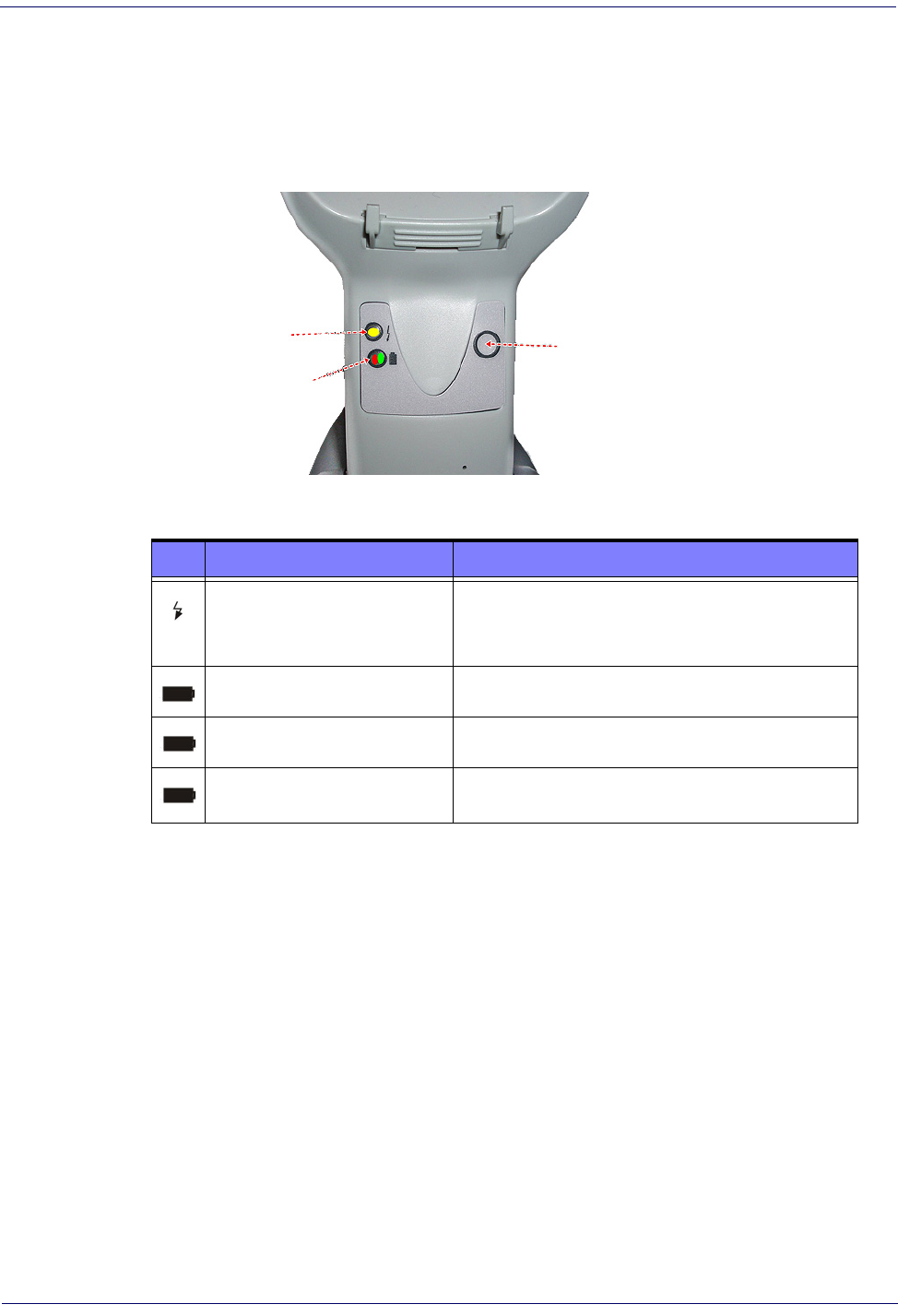
LEDs on the Gryphon Base provide information about the Base’s status, as shown in Figure 1.
Figure 1
YELLOW LED
RED LED /
GREEN LED
BUTTON
. Gryphon Base LEDs
The following table describes the significance of each LED:
LEDSTATUS
Power on / Data
Yellow On = Base is powered
Yellow Blinking = Base receives data and
commands from the Host or the Reader.
ChargingRed On = Battery charging is in progress.
Charge completedGreen On = the Battery is completely charged.
Charging + Charge completed
Red and Green Blinking together = the Reader
is not
correctly placed onto the Base.
See Base Station Indications (Cordless Models ONLY) on page 302 for more specific details on the
LEDs.
Base Button
The Base contains a button which is used primarily to perform a paging function. Pressing the
button causes a sound signal to be emitted by all scanners linked with this Base, as long as the
scanner is awake (see Powerdown Timeout on page 250) and reception is enabled (see LED and
Beeper Indicators on page 92). The button can also be used to "force device connection" via the
Datalogic Aladdin Software tool (available for free download from the Datalogic website). See
the Aladdin
Online Help for details.
See "Base Station Button Indicators" on page 302 for further information on Base Button
functions.
BC40XX UV Counterfeit DetectionIntroduction
Product Reference Guide
13
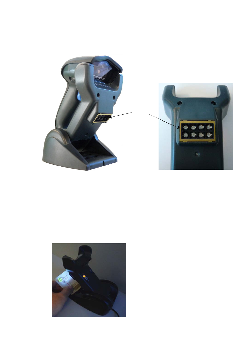
BC40XX UV Counterfeit Detection
The BC40XX Radio Base is available with a UV Counterfeit Money Detector, typically used to
verify the authenticity of bank notes. Other uses for counterfeit detection are passport, ticket,
credit card, travelers’ check and similar applications where it is possible to detect fluorescent
marks with UV light.
The detector contains eight special UV LEDs, as shown below:
UV LEDs
The Counterfeit Detector is based on UV fluorescent emission. Real banknotes under
ultraviolet rays usually absorb the UV light and will show special marks made with fluorescent
inks. On the other hand, most counterfeit banknotes only reflect the UV lights, without
showing fluorescent marks.
To use:
1.Quickly press the Base button to light the UV LEDs.
2.Hold the item to be verified under the LED lights to ensure that the special fluorescent
marks are visible.
IntroductionBattery Safety
14
Gryphon™ I GD44XX
/
GBT4400/GM440X
3.The LEDs are set to switch off automatically after about 2 minutes. To keep the UV LEDs
in always-on mode, quickly press the Base button a second time within 10 seconds of the
first press. To switch them off, simply press the button again.
An external power supply is necessary for full functionality of the Base station with UV
Counterfeit Detector. Use only the recommended AC adapter 12Vdc.
Battery Safety
To reinstall, charge and/or perform any other action on the battery, follow the instructions in
this manual.
WARNING
Do not discharge the battery using any device except for the scanner. When the battery is used in
devices other than the designated product, it may damage the battery or reduce its life expec-
tancy. If the device causes an abnormal current to flo
w, it may cause the battery to become hot,
explode or ignite and cause serious injury.
Lithium-ion battery packs may get hot, explode or ignite and cause serious injury if exposed to
abusive conditions. Be sure to follow the safety warnings listed below:
•Do not place the battery pack in fire or heat.
•Do not connect the positive terminal and negativ
e terminal of the ba
ttery pack to each other
with any metal object (such as wire).
•Do not carry or store the battery pack together with metal objects.
•Do not pierce the battery pack with nails, strike it w
i
th a hammer, step on it or otherwise sub-
ject it to strong impacts or shocks.
•Do not solder directly onto the battery pack.
•Do not expose the battery pack to liquids
,
or allow the battery to get wet.
•Do not apply voltages to the battery pack contacts.
WARNING
In the event the battery pack leaks and the fluid gets into your eye, do not rub the eye. Rinse well
with water and immediately seek medical care. If left untreated, the battery fluid could cause
damage to the eye.
Before installing the Battery, read “Battery Safety” on this and the following pages. Datalogic rec-
ommends annual replacement of rechargeable batter
y packs to ensure maximum performance.
CAUTION
Always charge the battery at 32° – 104°F (0° - 40°C) temperature range.
Use only the authorized power supplies, battery pack
, chargers, and docks supplied by your Data-
logic reseller. The use of any other power supplies can damage the device and void your warranty.
Do not disassemble or modify the battery. The batter
y
contains safety and protection devices,
which, if damaged, may cause the battery to generate heat, explode or ignite.
Do not place the battery in or near fire, on stoves or other high temperature locations.
Do not place the battery in direct sunlight, or use or st
or
e the battery inside cars in hot weather.
Doing so may cause the battery to generate heat, explode or ignite. Using the battery in this man-
ner may also result in a loss of performance and a shortened life expectancy.
Do not place the battery in microwave ovens, high-pr
e
ssure containers or on induction cookware.
Immediately discontinue use of the battery if, while using
, charging or storing the battery, the bat-
tery emits an unusual smell, feels hot, changes color or shape,
or appears abnormal in any other
way.
Do not replace the battery pack when the device is turned on.
Do not remove or damage the battery pack’s label.
Do not use the battery pack if it is damaged in any part.
Battery pack usage by children
should be supervised.
Battery SafetyIntroduction
Product Reference Guide
15
As with other types of batteries, Lithium-Ion (LI) batteries will lose capacity over time. Capacity
deterioration is noticeable after one year of service whether the battery is in use or not. It is
difficult to precisely predict the finite life of a LI battery, but cell manufacturers rate them at
500 charge cycles. In other words, the batteries should be expected to take 500 full discharge /
charge cycles before needing replacement. This number is higher if partial discharging /
recharging is adhered to rather than full / deep discharging.
Storage of batteries for long time at fully charged status or at fully discharged status should be
avoided.
Only in case of long storage, to avoid deep discharge of the battery it is recommended to partially
recharge the battery every three months to keep the charge status at a medium level.
As a reference, run a fast recharge for 20 minutes ev
er
y three months on unused products to avoid
any performance deterioration of the cell.
The useful life of LI batteries depends on usage and number of charges, etc., after which they
should be removed from service, especially in mission critical applications. Do not continue to
use a battery showing excessive loss of capacity, it should be properly recycled / disposed of and
replaced.
Collect and recycle waste batteries separately from
the device in compliance with European
Directive 2006/66/EC, 2002/95/EC, 2002/96/EC and subsequent modifications, US and
China regulatory and others laws and regulations about the environment.
IntroductionProgramming the Reader
16
Gryphon™ I GD44XX
/
GBT4400/GM440X
Programming the Reader
Configuration Methods
Programming Bar Codes
The reader is factory-configured with a standard set of default features. After scanning the
interface bar code, you can select other options and customize your reader through use of the
instructions and programming bar code labels available in the corresponding features section for
your interface. Customizable settings for many features are found in "Configuration Parameters"
starting on page 37.
Some programming labels, like "Restore Custom Defaults" on page34, require only the scan of the
single label to enact the change. Most, however, require
the reader to be placed in Programming
Mode prior to scanning them. Scan an ENTER/EXIT bar code once to enter Programming
Mode. Once the reader is in Programming Mode, scan a number of parameter settings before
scanning the ENTER/EXIT bar code a second time, which will then accept your changes, exit
Programming Mode and return the reader to normal operation.
There are some exceptions to the typical programming sequence described
above. Please read the description and setting instructions carefully when
configuring each programmable feature.
Datalogic Aladdin™
Datalogic Aladdin™ is a multi-platform utility program providing a quick and user-friendly
configuration method via the RS-232/USB-COM interface. Aladdin is available on the CD-
ROM provided with your product, and also from the Datalogic website. Aladdin allows you to
program the reader by selecting configuration commands through a user-friendly graphical
interface running on a PC. These commands are sent to the reader over the selected
communication interface, or they can be printed as bar codes to be scanned.
Aladdin also provides the ability to perform a soft
ware upgrade for the connected device (see the
Datalogic Aladdin™ Help On-Line for more details).
Product Reference Guide
17
Chapter 2
Setup
Unpacking
Check carefully to ensure the reader and any accessories ordered are present and undamaged. If
any damage occurred during shipment, contact Datalogic Technical Support. Information is
shown on
page10
.
KEEP THE PACKAGING. Should the unit ever require s
ervice, it should be returned in its
original shipping container.
Setting Up the Reader
Depending on whether you are using a Corded or BT version of the Gryphon, follow the steps
provided in this section to connect and get your reader up and communicating with its host.
1.Begin by
Installing the Interface Cable (Corded) or Connecting the Base Station (BT)
2.Go to
Interface Selection
and set the desired interface.
3.
Configure Interface Settings
(only if not using factory settings for that interface)
4.Go to
Configuring Other Features
(if modifications are needed from factory settings)
SetupInstalling the Interface Cable
18
Gryphon™ I GD44XX
/
GBT4400/GM440X
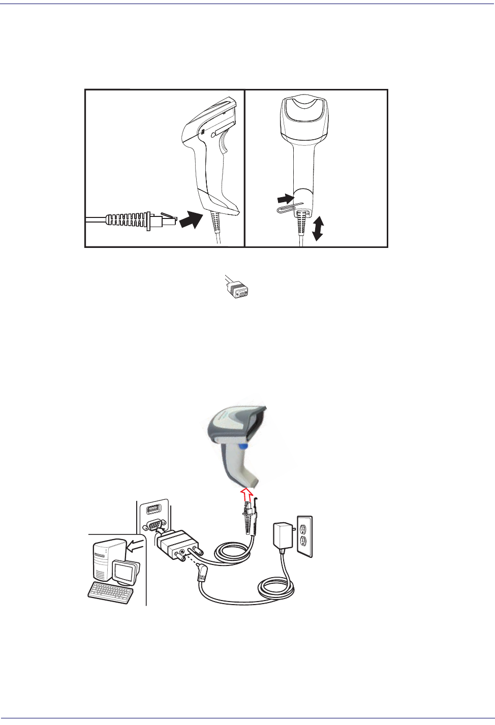
Installing the Interface Cable
For Corded versions, connect the reader cable by inserting the cable into the handle as shown in
Figure 2
. To remove it, insert a paper clip into the release aperture, then unplug the cable.
Figure 2. Connect/disconnect the cable
RS-232 Serial Connection
Turn off power to the terminal/PC and connect the reader to the terminal/PC serial port via the
RS-232 cable as shown in
Figure 3
. If the terminal will not support POT (Power Off the
Terminal) to supply reader power, use the approved power supply
(AC Adapter). Plug the AC
Adapter barrel connector into the socket on the RS-232 cable connector and the AC Adapter
plug into a standard power outlet.
Figure 3. RS-232 Connection
Installing the Interface CableSetup
Product Reference Guide
19
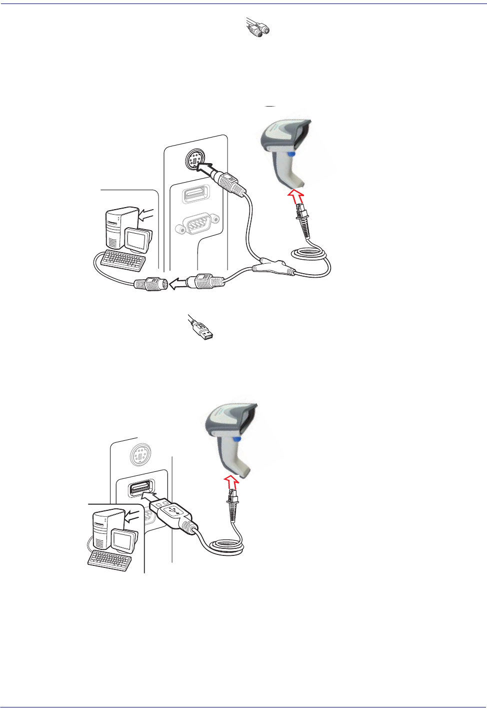
Keyboard Wedge Connection
The Keyboard Wedge cable has a ‘Y’ connection from the reader. Connect the female to the
male end from the keyboard and the remaining end at the keyboard port at the terminal/PC.
Reference
Figure 4
.
Figure 4. Keyboard Wedge Interface connection
USB Connection
Connect the reader to a USB port on the terminal/PC using the correct USB cable for the
interface type you ordered. Reference
Figure 5
.
Figure 5. USB connection
Other connection types are described below and illustrated in
Figure 6
.
SetupConfiguring the Base Station
20
Gryphon™ I GD44XX
/
GBT4400/GM440X
Figure 6. Other Interface Connections
W
a
n
d
I
B
M
K
e
y
b
o
a
r
d
W
e
d
g
e
or...
or...
Specific cables are required for connection to different hosts. The connec-
tors illustrated above are examples only. A
ctual connectors may vary from
those illustrated, but the steps to connect the reader remain the same.
RF Models
The power supply connects directly to the base (not on the cable's jack) for all configurations.
For all interfaces (except RS-232) a power supply is recommended but not necessary, because
the base can be powered from the Host. When the base is powered from the Host, select a slow
charge rate.
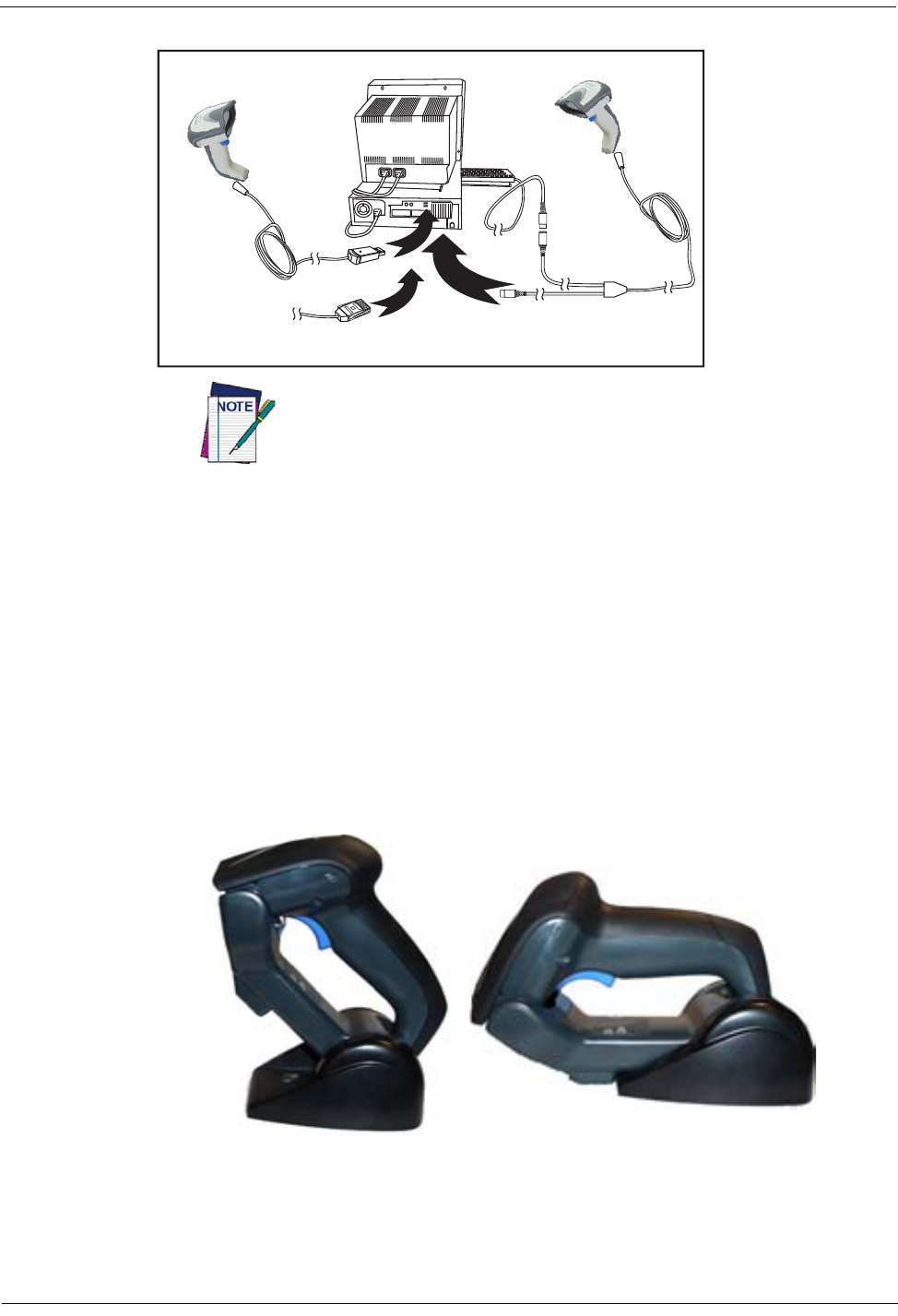
Configuring the Base Station
The base charger/station may be configured in desk application to hold the reader in two
different positions, either a horizontal or standing position, in order to provide the most
comfortable use depending on needs.
Standing
Horizontal
Configuring the Base StationSetup
Product Reference Guide
21
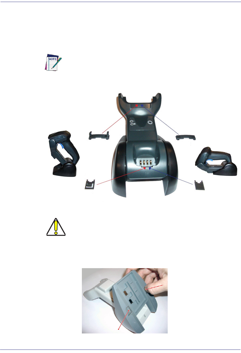
Changing the Base Station Position
The base station is configured by installing one of two sets of mechanical parts that come with
the cordless kit. The default mounts (shown below) provide three options: vertical (wall)
mounting, standing (45°), or horizontal mounting with a higher mechanical retention of the
scanner. Use the other mounts only for horizontal mounting, with lower retention of the
scanner. The different parts may be interchanged to customize retention preferences.
A tool such as a rigid pen or a flat screwdriver can be used to change the
mounts. Do not allow it to touch the contacts.
1.Insert the appropriate parts for the desired base station position, as shown below.
Standing,
Horizontal
or Vertical
Horizontal
ONLY
CAUTION
To ensure best contact and performance, do not intermix the parts of the two
different mount sets.
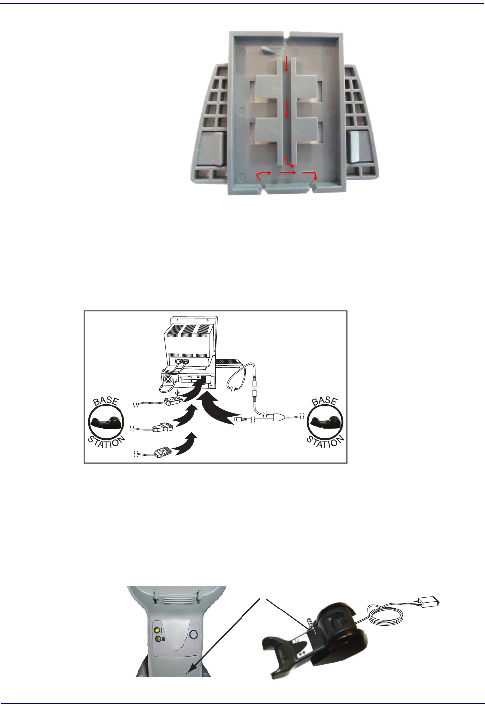
2.Using your thumbs, push open the plastic tabs on the bottom of the base to free the wing
holders.
Tab
Tab
SetupConfiguring the Base Station
22
Gryphon™ I GD44XX
/
GBT4400/GM440X
3.The stand can now be repositioned in either horizontal or standing position.
Horizontal
Standing
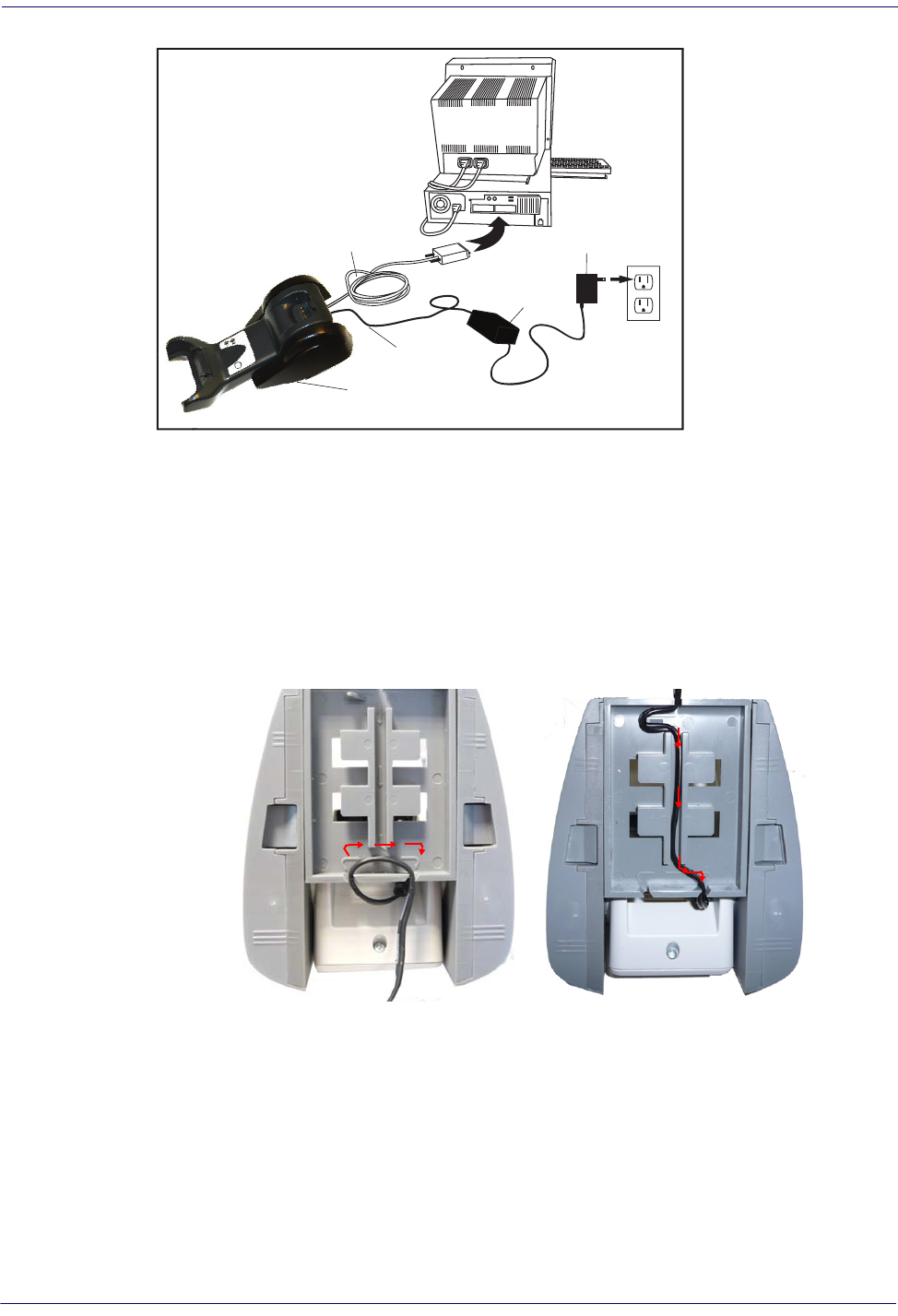
Connecting the Base Station
Figure 7
shows how to connect the Base Station to a terminal, PC or other host device. Turn off
the host before connection and consult the manual for that equipm
ent (if necessary) before
proceeding. Connect the interface cable before applying power to the Base Station.
The Gryphon GBT4400 can be set up to require a PIN code when connecting to the
host. If you are connecting to a system that uses a custom security PIN, follow the
procedure in
"Connecting the Base when Security Pin is Enabled" on page
25
. For
information on how to configure this feature, see
"BT Security Mode" starting on page
247
.
Base Station Connection and Routing:
Fully insert the Power Cable and Interface (I/F) Cable
connectors into their respective ports in the underside of the Base Station (see
Figure 7
). Then
connect to an AC Adapter, and plug the AC power cord into the (wall) outlet.
Gryphon Wireless can also be Powered by the Terminal. When powered by the Ter-
minal, the battery charger is automatically set as Slow charge.
For some specific interfaces or hosts or lengths of cable
,
the use of an external
power supply may be recommended for full recharging capability (see
"Technical
Specifications" on page293
for more details).
Configuring the Base StationSetup
Product Reference Guide
23
Figure 7. Connecting the Base Station
Base
Station
I/F Cable
AC/DC
Adapter
DC Power
Cord
Wall plug
Connector
Securing the DC Power Cord (Optional)
The DC power cord for the adapter can be secured to the bottom of the base in order to
maximize the mechanical retention of the cable itself. The routing of the power cord can be
changed to accommodate the base station positioning: horizontal, stand or wall mounting. The
cables can be looped around to the front of the Base Station, or fed directly out the back of the
Base Station, as shown in
Figure 8 on page 23
.
Figure 8. Options for routing the DC cord
Please refer to the arrows depicted on the bottom of the base when placing the cables, detailed in
Figure 9
.
SetupConfiguring the Base Station
24
Gryphon™ I GD44XX
/
GBT4400/GM440X
Figure 9. Arrows showing routing
Host Connection:
Verify before connection that the reader’s cable type is compatible with your
host equipment.
Most connections plug directly into the host device as shown in
Figure 10
. Keyboard Wedge
interface cables have a ‘Y’ connection where its female end mates with the male end of the cable
from the keyboard and the remaining end
at the keyboard port on the terminal/PC.
Figure 10. Connecting to the Host
U
S
B
I
B
M
K
e
y
b
o
a
r
d
W
e
d
g
e
W
a
n
d
or...
or...
or...
Power Connection :
Plug the AC Adapter in to an approved AC wall socket with the cable
facing downwards (as shown in
Figure 7
) to prevent undue strain on the socket.
Disconnecting the Cable:
To detach the cable, insert a paper clip or similar object into the hole
on the base, as shown in
Figure 11
.
Figure 11. Disconnecting the Cable
Insert
Paper Clip
Configuring the Base StationSetup
Product Reference Guide
25
Connecting the Base when Security Pin is Enabled
When connecting the Base to a system that has a custom Security Pin enabled, follow the steps
below in the order shown:
1.Power down the host system.
2.Connect the appropriate interface
cab
le into the Base as shown in
Figure 10
.
3.Place the reader in the Base.
4.Power up the host. The reader will link to the Base
5.When the host completely powers up, a new custom Security Pin Code may be sent to the
r
e
ader and Base, depending on host configuration. Contact Datalogic Technical Support
for more information.
If you want to change security settings or set up a PIN, see
"BT Security
Mode" starting on page 247
.
Linking the Reader to a Base Station
RF Devices
For RF devices, before configuring the interface it is necessary to link the handheld with the
base. To link the handheld and the base, press the trigger to wake it and place it on the base. If
the reader was previously linked to another base, you must first scan the Unlink action
command before re-linking to the new base.
Unlnk
Unlnk
BT Models only
Remember: The mandatory condition for establishing a new linking between a BT handheld
and a BT base is that the handheld is unlinked and they share the same security configuration. A
successful link is indicated by three ascending tones from the reader. A high-low-high-low tone
indicates the link attempt was unsuccessful. A single green LED flash after this tone indicates no
Base Station was discovered. Two green LED flashes after this tone indicates that more than one
Base Station was discovered and the reader did not link. Three LED flashes after this tone
indicate a security error.
SetupConfiguring the Base Station
26
Gryphon™ I GD44XX
/
GBT4400/GM440X
Linking a BT Reader to a PC
The reader can optionally be linked to a Bluetooth-enabled PC with the serial port profile, in
either server mode or client mode.
Linking to a PC in Server Mode (BT Slave Mode)
To link a BT reader in server mode to a Bluetooth-enabled PC, follow these steps:
1.Install any drivers provided with the Bluetooth adapter.
2.Scan thebar code bel
ow to make the scanner visible to the host computer.
³LnkSv
Link to a PC in Server Mode
3.Use the host computer’s Bluetooth manager to “Discover new devices” and select "Data-
logic Scanner." If you receive an error message, it may be necessary
to disable security on
the device.
4.Select “connect” on the PC to link the reader to the PC. Use an RS-232 terminal program
to see incoming
data on the port designated by the computer's Bluetooth manager.
Linking to a PC in Client Mode (BT Master Mode)
The reader can optionally be linked in client mode to a Bluetooth-enabled PC with the serial
port profile. To do this, follow these steps:
1.Ensure the PC or terminal can network with B
l
uetooth devices and that it is powered on.
2.Ensure that a COM port is assigned under Services within the Bluetooth setup menu.
3.Create a Link label that contains the addr
ess of
the PC Bluetooth adapter.
NOTE
The Bluetooth address can be found under "Properties" within in the
Bluetooth setup menu.
The link label is a Code 128 function 3 label with the following format:
<FN3 char>Ln
kB<12 character Bluetooth address>
4.Scan the link label you created in step 3.
Power Off
Shuts off power to the BT handheld until next trigger pull. This function only applies to the BT
model.
Gryphon™ 2D System and Network LayoutsSetup
Product Reference Guide
27
Gryphon™ 2D System and Network Layouts
Stand Alone Layouts
Figure 12. Single Reader Layout
Figure 13. Multiple Reader Layout
Wireless models only
(not valid for BT model)
In stand alone systems, each base station is connected to a single Host.
SetupGryphon™ 2D System and Network Layouts
28
Gryphon™ I GD44XX
/
GBT4400/GM440X
Figure 14. Multiple Stand Alone Layouts
Mobile models only
(not valid for BT model)
Many stand alone connections can operate in the same physical area without interference,
provided all readers and base stations in the system have different addresses.
Interface SelectionSetup
Product Reference Guide
29
Interface Selection
Upon completing the physical connection between the reader and its host, proceed to Table 1
starting on page 30
to select the interface type the reader is connected to (for example: RS-232,
Keyboard Wedge, USB, etc.). Scan the appropriate bar code in that section to configure your
syst
em’s correct interface type.
Each reader model will support one of the following sets of host interfaces:
General Purpose ModelsRetail Point of Sale Models
•RS-232
•RS-232 OPOS
•USB-COM
•Keyboard Wedge
•Wand Emulation (BT only)
•RS-232
•RS-232 OPOS
•USB
•IBM 46XX
Setting the Interface
Scan the programming bar code from this section which selects the appropriate interface type
matching the system the reader will be connected to. Next, proceed to the corresponding
section in this manual (also listed in
Table1 on page30
) to configure any desired settings and
features associated with that interface.
Unlike some programming features and options, interface selections
require that you scan only one programming bar code label. DO NOT
scan an ENTER/EXIT bar code prior to scanning an interface selection bar
code.
Some interfaces require the scanner to star
t in the disabled state when
powered up. If additional scanner configuration is desired while in this
state, pull the trigger and hold it for five seconds. The scanner will
change to a state that allows programming with bar codes.
SetupInterface Selection
30
Gryphon™ I GD44XX
/
GBT4400/GM440X
Table1. Available Interfaces
RS-232FEATURES
RS-232 standard interface
Select RS232-STD
Set RS-232
Interface
Features
starting on
page 41
$P,HA12,P(CR)
Select RS232-WN
RS-232 Wincor-Nixdorf
RS-232 for use with OPOS/UPOS/JavaPOS
$P,HA13,P(CR)
Select RS-232 OPOS
$P,HA47,P(CR)
Select USB-COM-STD
a
a.Download the correct USB Com driver from www.datalogic.com
USB Com to simulate RS-232 standard interface
IBM
FEATURES
$P,HA08,P(CR)
Select IBM-P5B
IBM-46xx Port 5B reader interface
Set IBM
Interface
Features
starting on
page 67
IBM-46xx Port 9B reader interface
$P,HA23,P(CR)
Select IBM-P9B
USB-OEMFEATURES
$P,HA45,P(CR)
Select USB-OEM
USB-OEM
(can be used for OPOS/UPOS/JavaPOS)
Set USB-OEM
Interface
Features
starting on
page 65
KEYBOARDFEATURES
$P,HA2B,P(CR)
Select USB Alternate Keyboard
USB Keyboard with alternate key encoding
AT, PS/2 25-286, 30-286, 50, 50Z, 60, 70,
80, 90 & 95 w/Standard Key Encoding
$P,HA29,P(CR)
Select KBD-AT
Set KEYBOARD
WEDGE
Interface
Features
starting on page
55
$P,HA11,P(CR)
Select KBD-AT-NK
Keyboard Wedge for IBM AT PS2 with
standard key encoding but without
external keyboard
AT, PS/2 25-286, 30-286, 50, 50Z, 60, 70,
80, 90
& 95 w/Alternate Key
$P,HA26,P(CR)
Select KBD-AT-ALT
$P,HA10,P(CR)
Select KBD-AT-ALT-NK
Keyboard Wedge for IBM AT PS2 with
alternate key encoding but without
external keyboard
PC/XT w/Standard Key Encoding
$P,HA28,P(CR)
Select KBD-XT
$P,HA14,P(CR)
Select KBD-IBM-3153
Keyboard Wedge for IBM Terminal 3153
Interface SelectionSetup
Product Reference Guide
31
KEYBOARD — cont.FEATURES
Keyboard Wedge for IBM Terminals
31xx, 32xx, 34xx, 37xx make
only key-
board
$P,HA15,P(CR)
Select KBD-IBM-M
Set KEYBOARD
WEDGE
Interface
Features
starting on page 55
$P,HA16,P(CR)
Select KBD-IBM-MB
Keyboard Wedge for IBM Terminals
31xx, 32xx, 34xx, 37xx make break key-
board
Keyboard Wedge for DIGITAL Termi-
nals VT2xx, VT3xx, VT4xx
$P,HA1B,P(CR)
Select KBD-DIG-VT
$P,HA35,P(CR)
Select USB Keyboard
USB Keyboard with standard key encoding
USB Keyboard for Apple computers
$P,HA2C,P(CR)
Select USB-KBD-APPLE
WAND EMULATIONFEATURES
Wand Emulation
(BT only)
$P,HA24,P(CR)
Select WAND
Set WAND
Interface
Features
starting on page 71
SetupInterface Selection
32
Gryphon™ I GD44XX
/
GBT4400/GM440X
Customizing Configuration SettingsSetup
Product Reference Guide
33
Customizing Configuration Settings
Configure Interface Settings
If after scanning the interface bar code from the previous table, your installation requires you to
select options to further customize your reader, turn to the appropriate section for your interface
type in
"Configuration Parameters" starting on page 37
.
•
"RS-232 Interface" on page41
•
"RS-232/USB-Com Interfaces" on page 46
•
"Keyboard Settings" on page 55
•
"RS-232/USB-Com Interfaces" on page 46
•
"IBM 46XX Interface" on page67
•
"Wand Emulation Interface" on page71
Global Interface Features
See "
Global Interface Features" on page 39
for settings configurable by all interface types.
Configuring Other Features
If your installation requires different programming than the standard factory default settings,
the following sections of this manual allow configuration of non-interface-specific settings you
might require:
Reading Parameters
:
Reading Parameters include programming for scanning, beeper and LED
indicators and other universal settings.
1D Symbologies
:
Includes options concerning the bar code label types (symbologies). These
settings allow you to enable/disable symbologies, set label lengths, require check digit, etc.
WIRELESS FEATURES
:
Contains programming options for RF, STAR and Bluetooth models only.
Software Version Transmission
The software version of the device can be transmitted over the RS-232 and Keyboard interfaces
by scanning the following label.
Transmit Software Version
RevA
SetupCustomizing Configuration Settings
34
Gryphon™ I GD44XX
/
GBT4400/GM440X
Resetting the Product Configuration to Defaults
Restore Custom Defaults
If you aren’t sure what programming options are in your imager, or you’ve changed some
options and want to restore the Custom Default Configuration that may have been saved in the
scanner, scan the Restore Custom Default Configuration bar code below. This will restore the
custom configuration for the currently active interface.
Restore Custom Default Configuration
$P,HA00,P(CR)
Custom defaults are based on the interface type. Configure the imager
for the correct interface before scanning this label.
Restore Factory Configuration
If you want to restore the Factory Configuration for your imager, scan either the Restore USA
Factory Configuration bar code or the Restore EU Factory Configuration bar code below. Both
labels restore the scanner configuration to the factory settings, including the interface type. The
USA label restores Label IDs to those historically used in the USA. The EU label restores Label
IDs to those historically used in Europe. The Label ID sets for USA and EU are shown in the
“Label ID Control” section on page 81
of this manual.
$P,AE,P(CR)
Restore USA Factory Configuration
$P,Ae,P(CR)
Restore EU Factory Configuration
The programming items listed in the following sections show the factory default settings for
each of the menu commands.
Customizing Configuration SettingsSetup
Product Reference Guide
35
Replacing the Battery
Before replacing the Battery, read
"Battery Safety" starting on page 14
. Datalogic recommends
annual replacement of rechargeable battery packs to ensure maximum performance.
To change the battery of your reader, complete the following instructions.
1.With a screwdriver, unscrew the battery cover screw.
2.Unscrew and remove the three screws securing the battery holder, and unplug the white
connector.
Connector
Screw
Screw
3.Carefully lift out the gold contacts circuit, and remove the battery holder while letting the
white connector pass through the hole in the battery holder (as shown in the picture
below).
Pass-through
hole
Gold
contacts
circuit
SetupCustomizing Configuration Settings
36
Gryphon™ I GD44XX
/
GBT4400/GM440X
4.Remove the old battery from its place (if present), and insert the new battery in the same
position.
5.Replace the battery holder and three screws, plug in the connector, and return the contacts
circuit to its prev
ious location.
When inserting the new battery into the handle, take care to position the battery
and the connector as shown.
6.Insert the cover in the handle and screw it back into place.
Battery replacement is now complete.
Product Reference Guide
37
Chapter 3
Configuration Using Bar Codes
This and following sections provide programming bar codes to configure your reader by
changing the default settings. For details about additional methods of programming, see
"Configuration Methods" on page 16.
You must first enable your reader to read bar codes in order to use this
section. If you have not done this, go to
Setup,starting on page 17
and
complete the appropriate procedure.
Configuration Parameters
Once the reader is set up, you can change the default parameters to meet your application needs.
Refer to "Standard Defaults" starting on page 303 for initial configuration in order to set the
default values and select the interface for your application.
The following configuration parameters are divided into logical
groups, making it easy to find
the desired function based on its reference group.
Interface Configuration:
•"RS-232/USB-Com Interfaces" on page 46
•"Keyboard Settings" on page 55
Parameters common to all interface applications:
•"Data Format" on page75 gives options to control the messages sent to the Host system.
•"Reading Parameters" on page89 control various operating modes and indicators status
functioning.
Symbology-specific parameters:
•"1D Symbologies" on page111 provides configuration of a personalized mix of 1D codes,
code families and their options.
•"2D Symbologies" on page203 provides configuration of a personalized mix of 2D codes,
code families and their options.
You must first enable your reader to read bar codes in order to use this
section. If you have not done this, go to
Setup,starting on page 17
and
complete the appropriate procedure.
Enter/Exit Programming Mode
38
Gryphon™ I GD44XX
/
GBT4400/GM440X
To program features:
1.Scan the ENTER/EXIT PROGRAMMING bar code, available at the top of each pro-
gramming page, when applicable.
2.Scan the bar code to set the desired programming feature. You may need to cover unused
bar codes on the page, and possibly the facing page
, to ensure that the reader reads only
the bar code you intend to scan.
3.If additional input parameters are needed, go to Appendix D, Keypad, and scan the
appropriate characters from the keypad.
Additional information about many features can be found in the “Refer-
ences” chapter.
If you make a mistake before the last character, scan the CANCEL bar code
to
a
bort and not save the entry string. You can then start again at the
beginning.
4.Complete the programming sequence by scanning the ENTER/EXIT PROGRAM-
MING bar code to exit Programming Mode.
For more detailed descriptions, programming information and examples
for setting selected
configuration items, see References, starting on page 255.
By default, the handheld will decode bar code labels only when they are
close to the center of the aiming pattern. This allows the handheld to accu-
rately target labels when they are placed close together, such as on a
pick
sheet. See
Pick Mode, starting on page 100.
Global Interface FeaturesEnter/Exit Programming Mode
Product Reference Guide
39
GLOBAL INTERFACE FEATURES
The following interface features are configurable by all interface types.
Host Commands — Obey/Ignore
This option specifies whether the reader will obey or ignore host commands. When set to
ignore, the reader will ignore all host commands except for those necessary for:
•service mode
•flash programming mode
•keeping the interface active
•transmission of labels.
DEFAULT
$CIFIH00(CR)
Host Commands = Obey
(Do Not Ignore Host Commands)
$CIFIH01(CR)
Host Commands = Ignore
USB Suspend Mode
This setting enables/disables the ability of USB interfaces to enter suspend mode.
DEFAULT
$CUSSE00(CR)
USB Suspend Mode = Disable
$CUSSE01(CR)
USB Suspend Mode = Enable
Enter/Exit Programming ModeGlobal Interface Features
40
Gryphon™ I GD44XX
/
GBT4400/GM440X
NOTES
RS-232 INTERFACE
BAUD RATE on page 42
DATA BITS on page 43
STOP BITS on page 43
PARITY on page 44
HANDSHAKING CONTROL on page 45
Use the programming bar codes in this section if modifications to the stan
dard RS-232 interface settings are
necessary to meet your system’s requirements. Additional settings which apply to both the RS-232 and USB
interfaces are available in the next section, "RS-232/USB-Com Interfaces" start
ing on page46.
Reference Appendix B, Standard Defaults for a listing of standard factory settings.
Enter/Exit Programming ModeRS-232 Interface
42
Gryphon™ I GD44XX
/
GBT4400/GM440X
Baud Rate
See page 256 for information on this feature.
$CR2BA00(CR)
Baud Rate = 1200
$CR2BA01(CR)
Baud Rate = 2400
$CR2BA02(CR)
Baud Rate = 4800
$CR2BA03(CR)
Baud Rate = 9600
DEFAULT
$CR2BA04(CR)
Baud Rate = 19,200
$CR2BA05(CR)
Baud Rate = 38,400
$CR2BA06(CR)
Baud Rate = 57,600
$CR2BA07(CR)
Baud Rate = 115,200
RS-232 InterfaceEnter/Exit Programming Mode
Product Reference Guide
43
Data Bits
This parameter allows the reader to interface with devices requiring a 7-bit or 8-bit ASCII protocol for sending and
receiving data.
$CR2DA00(CR)
7 Data Bits
$CR2DA01(CR)
8 Data Bits
DEFAULT
Stop Bits
Set the number of stop bits to match host device requirements. See page 256 for more information on this feature.
DEFAULT
$CR2ST00(CR)
1 Stop Bit
$CR2ST01(CR)
2 Stop Bits
Enter/Exit Programming ModeRS-232 Interface
44
Gryphon™ I GD44XX
/
GBT4400/GM440X
Parity
This feature specifies parity required for sending and receiving data. Select the parity type according to host device
requirements. See page256 for more information.
DEFAULT
$CR2PA00(CR)
Parity = None
$CR2PA01(CR)
Parity = Even
$CR2PA02(CR)
Parity = Odd
RS-232 InterfaceEnter/Exit Programming Mode
Product Reference Guide
45
Handshaking Control
DEFAULT
$CR2HC00(CR)
Handshaking Control = RTS
$CR2HC01(CR)
Handshaking Control = RTS/CTS
$CR2HC02(CR)
Handshaking Control = RTS/XON/XOFF
$CR2HC03(CR)
Handshaking Control = RTS On/CTS
$CR2HC04(CR)
Handshaking Control = RTS/CTS Scan Control
See page 256 for more information about this feature.
RS-232/USB-COM INTERFACES
INTERCHARACTER DELAY on page 47
BEEP ON ASCII BEL on page 47
BEEP ON NOTON FILE on page 48
ACK NAK OPTIONS on page 49
ACK CHARACTER on page 50
NAK CHARACTER on page 50
ACK NAK TIMEOUT VALUE on page 51
ACK NAK RETRY COUNT on page 51
ACK NAK ERROR HANDLING on page 52
INDICATE TRANSMISSION FAILURE on page 52
DISABLE CHARACTER on page 53
ENABLE CHARACTER on page 53
The programming bar codes in this chapter allow modifica
tions to the standard RS-232 and USB-Com interfaces.
Reference Appendix B, Standard Defaults for a listing of standard factory settings.
Libble takes abuse of its services very seriously. We're committed to dealing with such abuse according to the laws in your country of residence. When you submit a report, we'll investigate it and take the appropriate action. We'll get back to you only if we require additional details or have more information to share.
Product:
Forumrules
To achieve meaningful questions, we apply the following rules:
First, read the manual;
Check if your question has been asked previously;
Try to ask your question as clearly as possible;
Did you already try to solve the problem? Please mention this;
Is your problem solved by a visitor then let him/her know in this forum;
To give a response to a question or answer, do not use this form but click on the button 'reply to this question';
Your question will be posted here and emailed to our subscribers. Therefore, avoid filling in personal details.
Register
Register getting emails for Datalogic Gryphon I GM4400 2D at:
new questions and answers
new manuals
You will receive an email to register for one or both of the options.
Get your user manual by e-mail
Enter your email address to receive the manual of Datalogic Gryphon I GM4400 2D in the language / languages: English as an attachment in your email.
The manual is 11,5 mb in size.
You will receive the manual in your email within minutes. If you have not received an email, then probably have entered the wrong email address or your mailbox is too full. In addition, it may be that your ISP may have a maximum size for emails to receive.
The manual is sent by email. Check your email
If you have not received an email with the manual within fifteen minutes, it may be that you have a entered a wrong email address or that your ISP has set a maximum size to receive email that is smaller than the size of the manual.
The email address you have provided is not correct.
Please check the email address and correct it.
Your question is posted on this page
Would you like to receive an email when new answers and questions are posted? Please enter your email address.