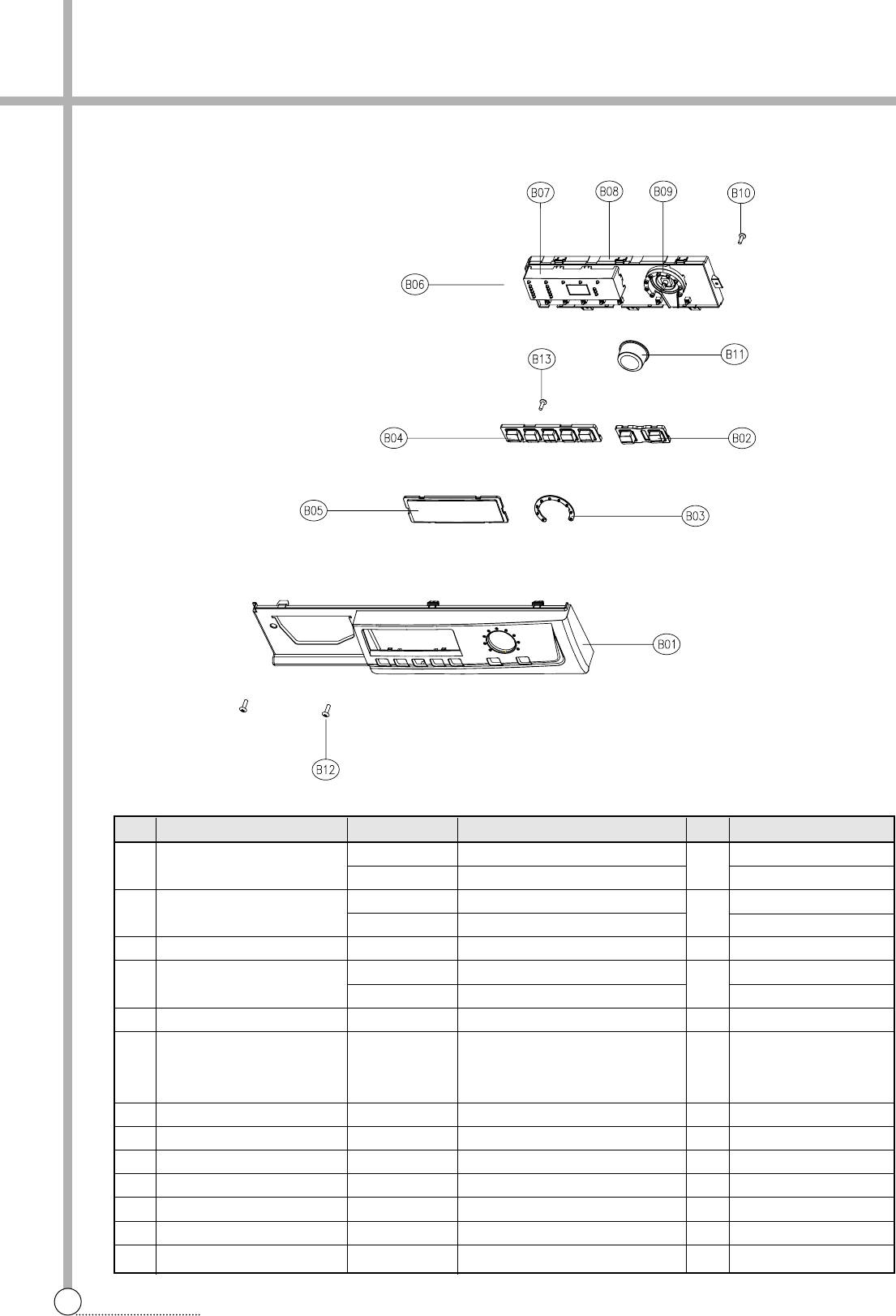
19
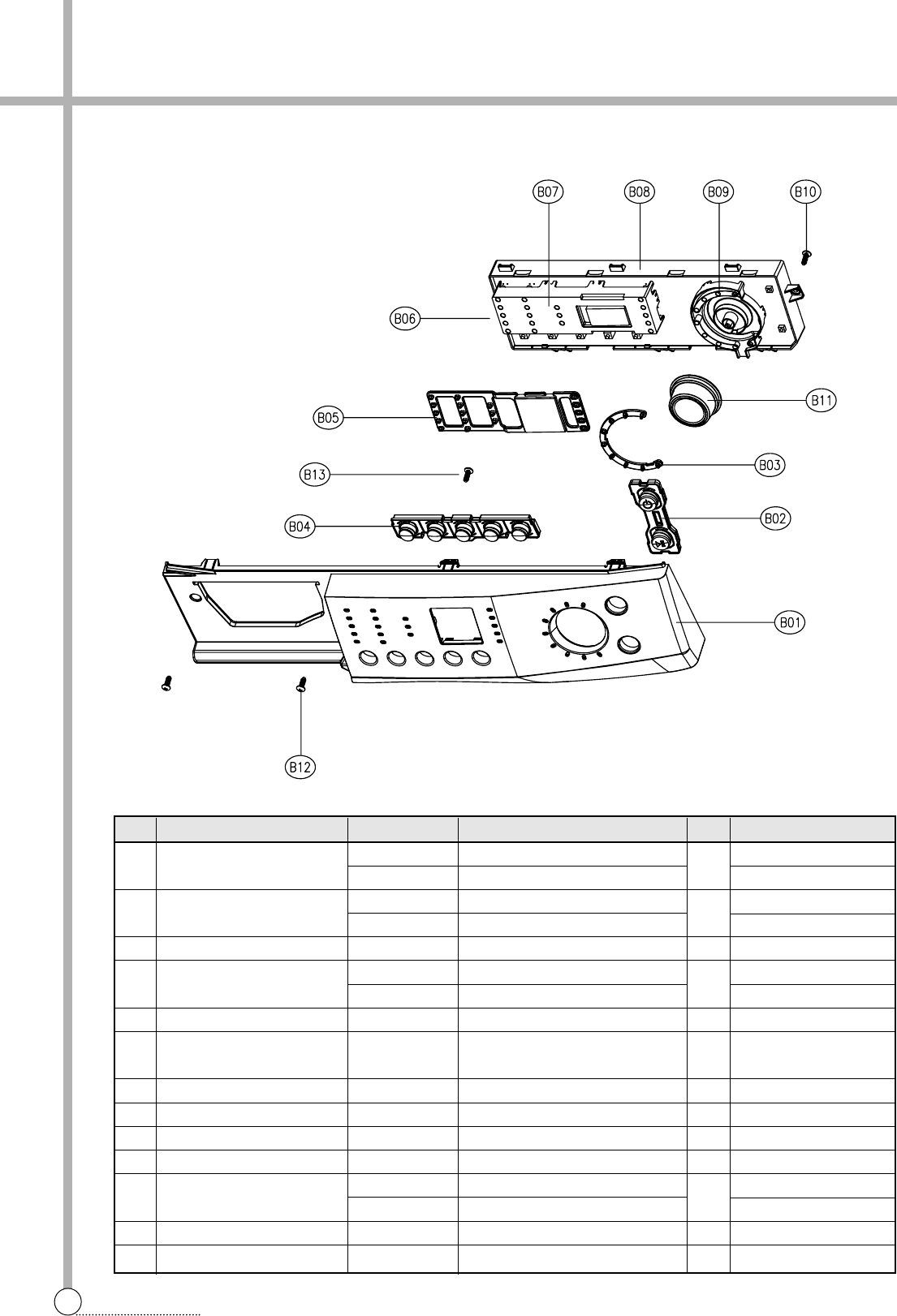
EXPLODE VIEW AND PARTS LIST
■ Detailed Part Code of PCB AS
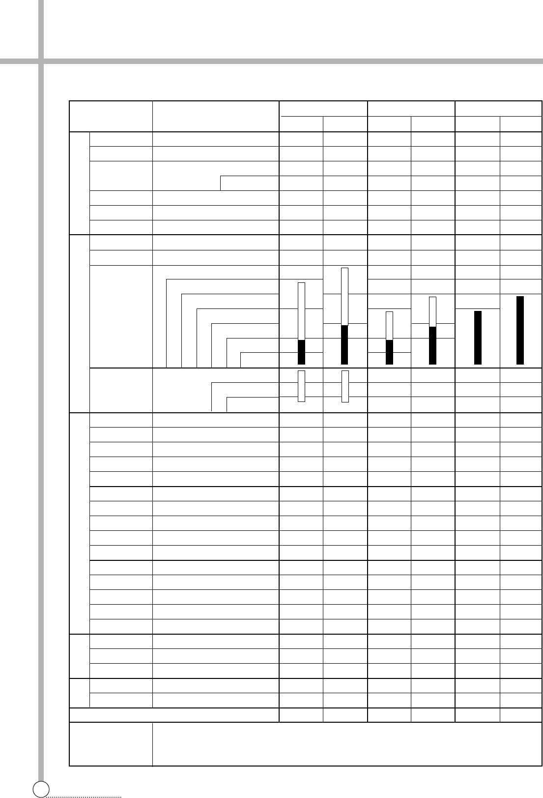
No. PART NAME PART CODE SPECIFICATION Q'TY REMARK
B06 PCB AS PRPSSWFD07 DWD-FD141’s, EC, COLD V/V, NON-BB 1 1st PANEL
PRPSSWFD08 DWD-FD141’s, EC, COLD V/V, BB
PRPSSWFD09 DWD-FD141’s, EC, HOT V/V, NON-BB
PRPSSWFD10 DWD-FD141’s, EC, HOT V/V, BB
PRPSSWFD11 DWD-FD141’s, NON-EC, COLD V/V, NON-BB
PRPSSWFD12 DWD-FD141’s, NON-EC, COLD V/V, BB
PRPSSWFD13 DWD-FD141’s, NON-EC, HOT V/V, NON-BB
PRPSSWFD14 DWD-FD141’s, NON-EC, HOT V/V, BB
PRPSSWFD15 DWD-FD143’s, NON-EC, HOT V/V, BB 2nd PANEL
PRPSSWFD30 DWD-FD143’s, NON-EC, HOT V/V, NON-BB
PRPSSWFD31 DWD-FD143’s, NON-EC, COLD V/V, BB
PRPSSWFD32 DWD-FD143’s, NON-EC, COLD V/V, NON-BB
PRPSSWFD33 DWD-FD143’s, EC, HOT V/V, BB
PRPSSWFD34 DWD-FD143’s, EC, HOT V/V, NON-BB
PRPSSWFD35 DWD-FD143’s, EC, COLD V/V, BB
PRPSSWFD36 DWD-FD143’s, EC, COLD V/V, NON-BB
PRPSSWFD50 DWD-FD142’s, NON-EC, HOT V/V, BB 3rd PANEL
PRPSSWFD51 DWD-FD142’s, NON-EC, HOT V/V, NON-BB
PRPSSWFD52 DWD-FD142’s, NON-EC, COLD V/V, BB
PRPSSWFD53 DWD-FD142’s, NON-EC, COLD V/V, NON-BB
PRPSSWFD54 DWD-FD142’s, EC, HOT V/V, BB
PRPSSWFD55 DWD-FD142’s, EC, HOT V/V, NON-BB
PRPSSWFD56 DWD-FD142’s, EC, COLD V/V, BB
PRPSSWFD57 DWD-FD142’s, EC, COLD V/V, NON-BB