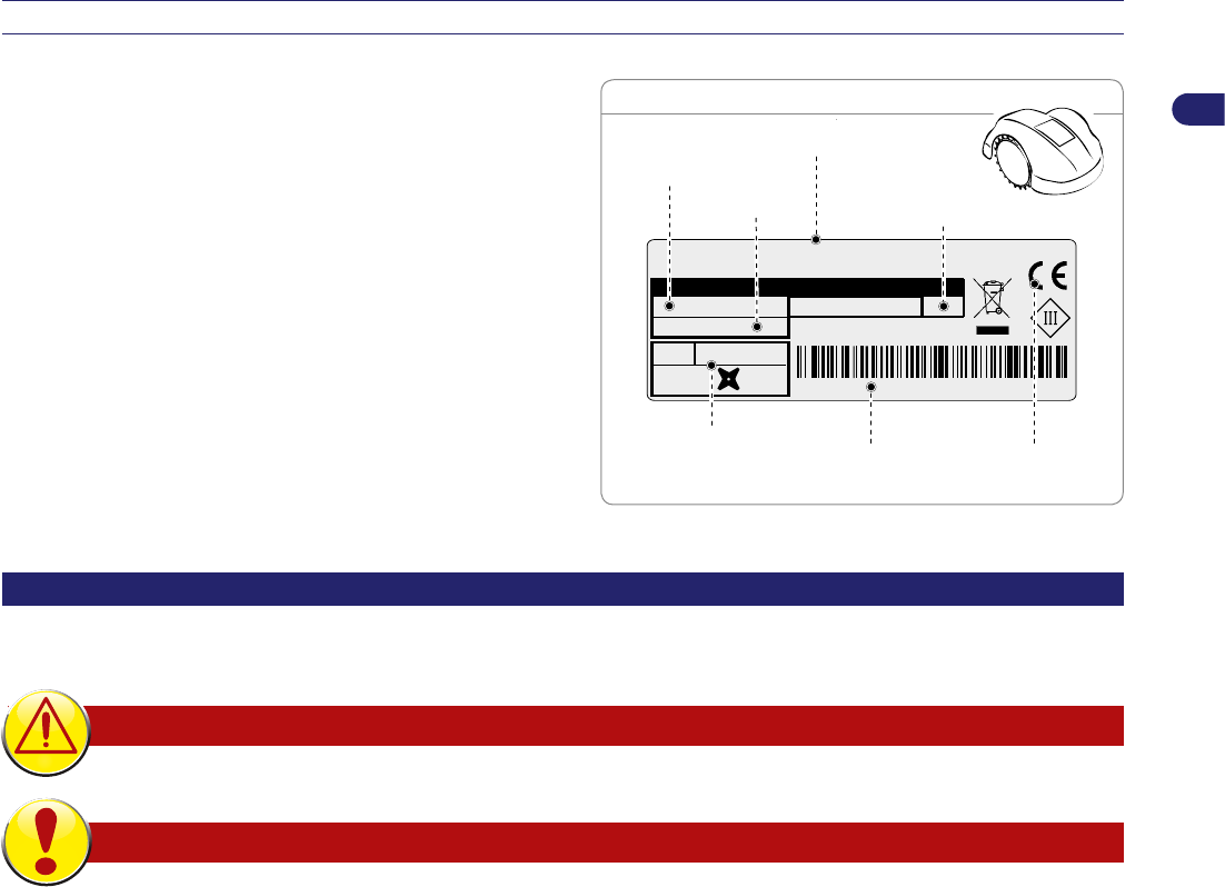
La sigla di identificazione del robot è riportata sulla targhetta applicata sul pannello frontale. Sulla base della sigla, è possibile
individuare, nella tabella riportata a piè di pagina, la denominazione commerciale del robot.
EN
The identification code of the robot can be found on the plate on the front panel. On the basic of the code you can find the trade name of
the robot in the table at the bottom of the page.
FR
Le sigle d’identification du robot est reporté sur la plaque appliquée sur le panneau avant. Ense basant sur le sigle, il est possible
d’identifier ladénomination commerciale du robot dans le tableau se trouvant au bas de la page.
DE
Das Typenschild mit der Kennnummer des Roboters befindet sich auf der vorderen Abdeckung des Gerätes. Anhand der Kennung kann
die Handelsbezeichnung des Roboters mit Hilfe der Tabelle am Seitenende festgerstellt werden.
NL
Het kenteken van de robot bevindt zich op het identificatieplaatje op het frontpaneel. Aan de hand van dit kenteken kan de commerciële
benaming van de robot in de tabel onderaan de bladzijde teruggevonden worden.
DA
På frontpladen er de en model-kode på robotter. På baggrund af koden er det muligt at identificere det kommercielle navn på robotten, i
tabellen, i bunden af siden.
SV
Robotens modellkod sitter på märkskylten på frontpanelen. Utifrån koden går det att identifiera robotens kommersiella beteckning, i
tabellen längst ner på sidan.
7085EV0 - Ambrogio Robot L85 Evolution
7085EL0 - Ambrogio Robot L85 Elite
1
User’s manual
EN
TABLE OF CONTENTS
General information. ...................................................................................................................................................................2
Purpose of the manual. ...............................................................................................................................................................2
Identication of manufacturer and equipment. ............................................................................................................................3
General description of the appliance...........................................................................................................................................7
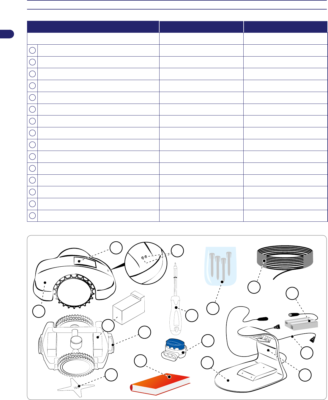
Main parts / standard equipment.................................................................................................................................................8
Packing and unpacking. ..............................................................................................................................................................9
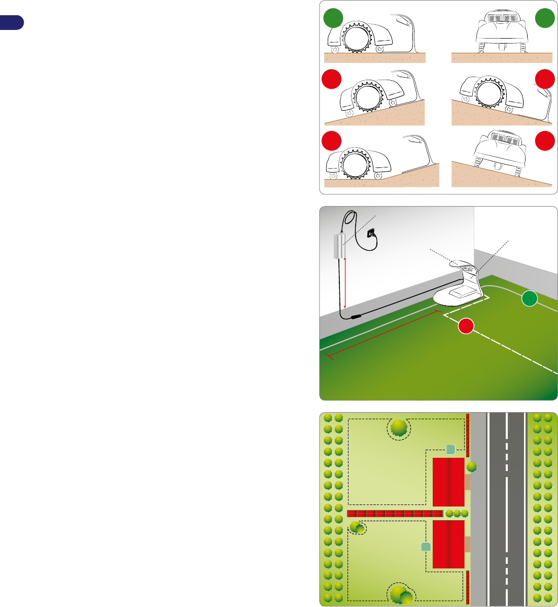
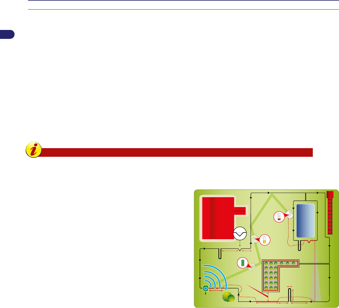
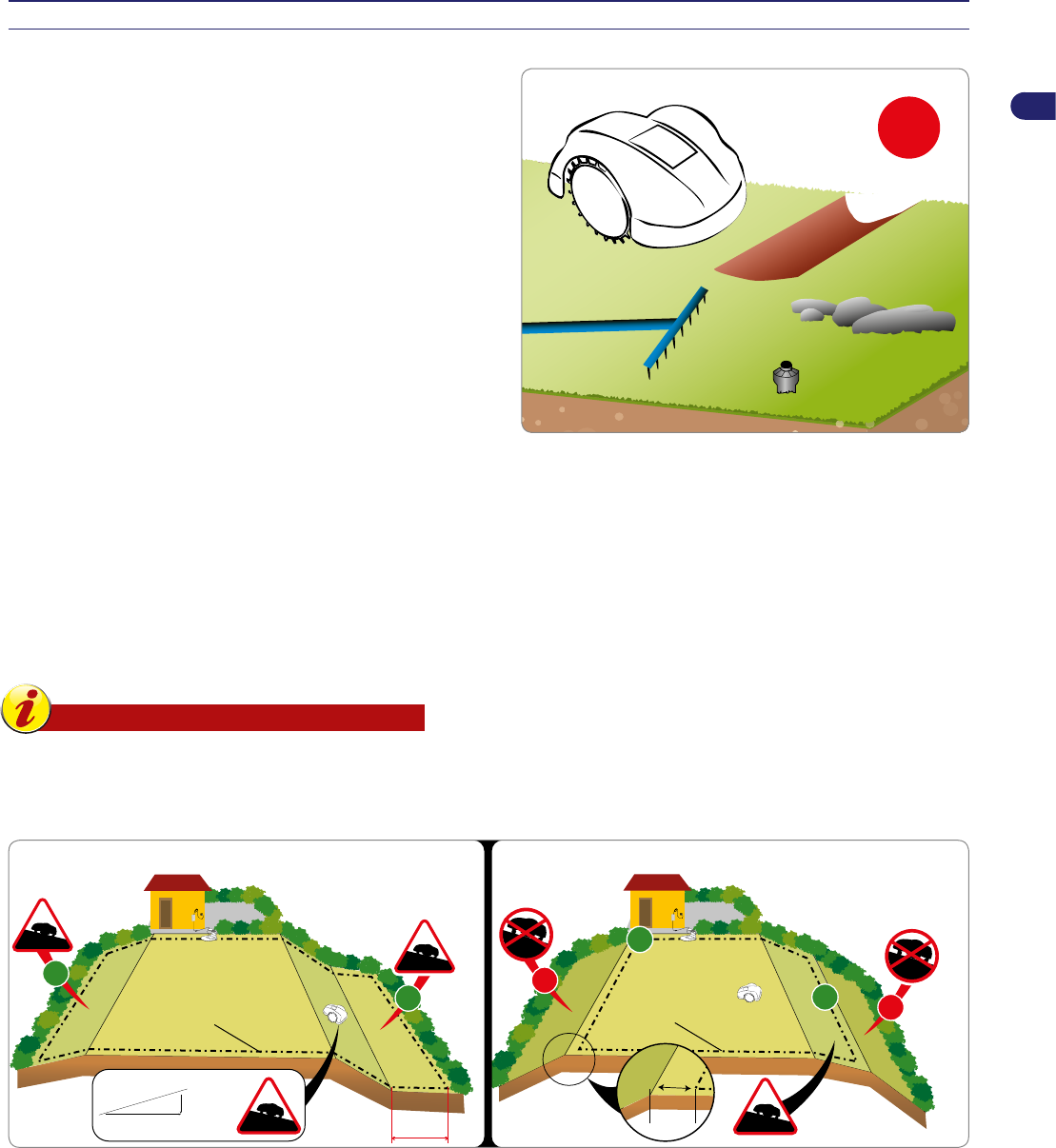
Planning of system installation. ...................................................................................................................................................9
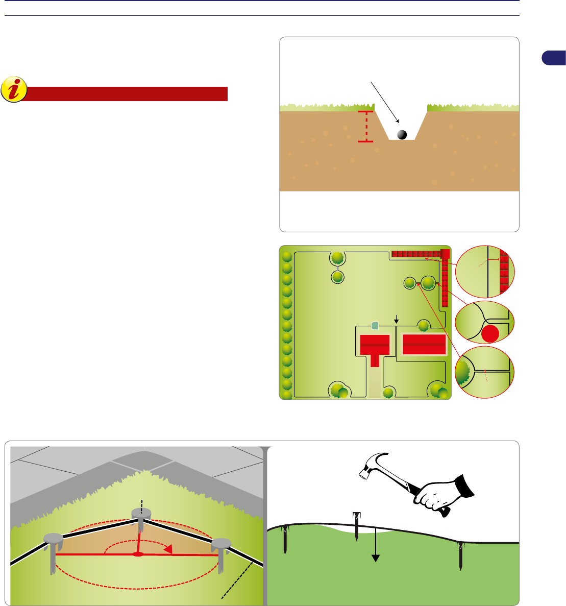
Setting up of the perimeter wire. ................................................................................................................................................11
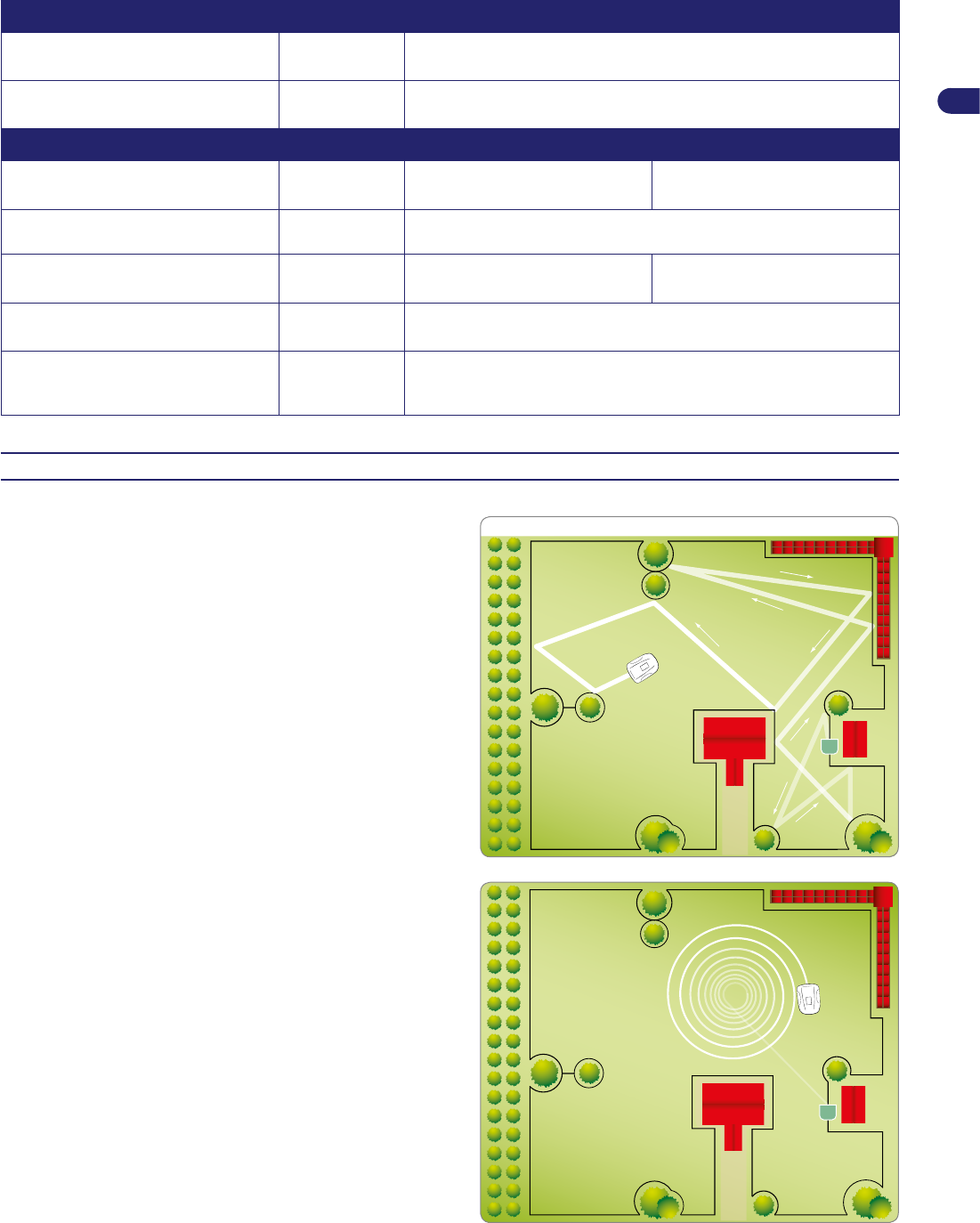
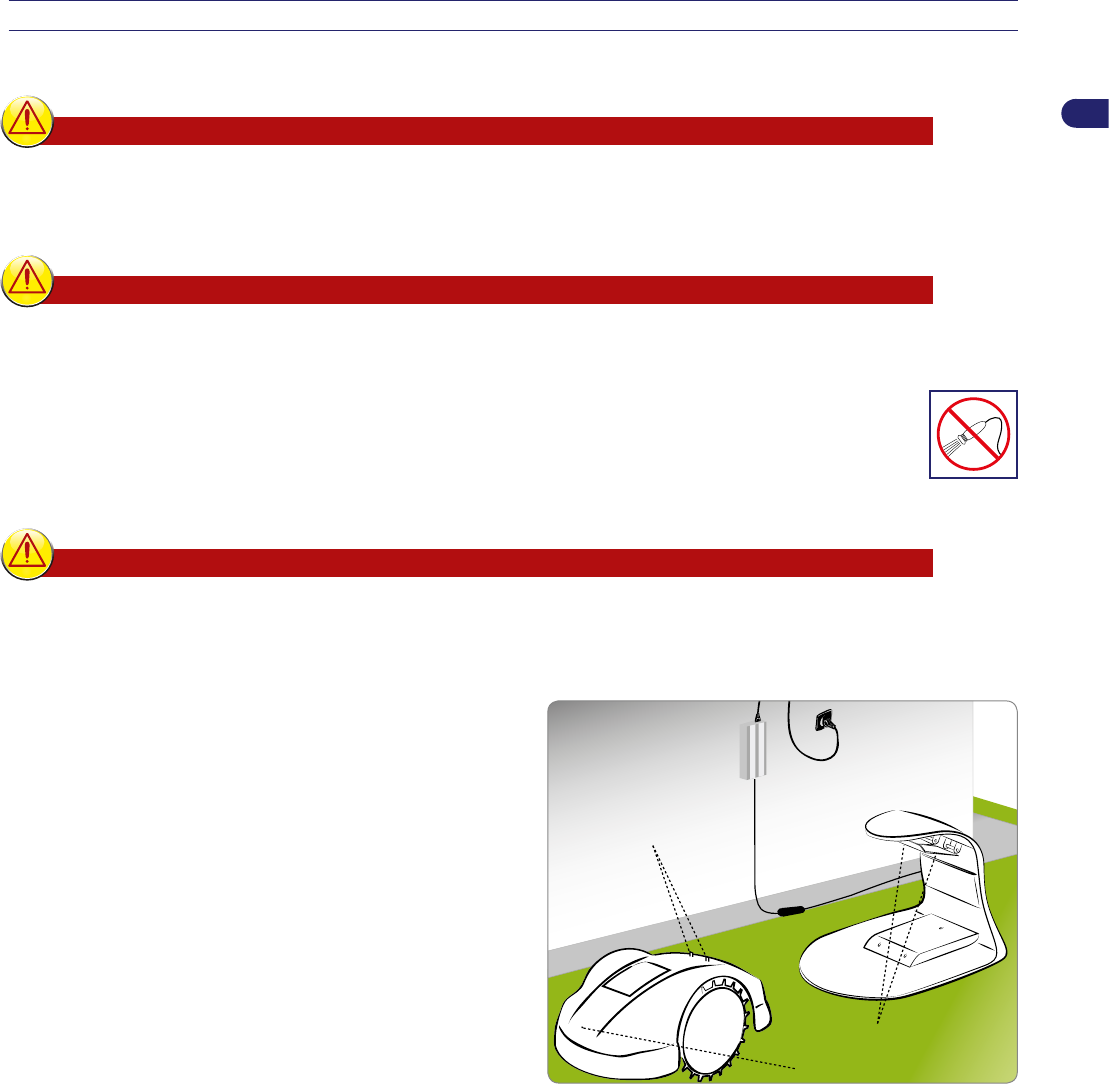
Re-entry method to the charging station. ...................................................................................................................................11
Setup of the robot’s quick re-entry to the charging station. .......................................................................................................12
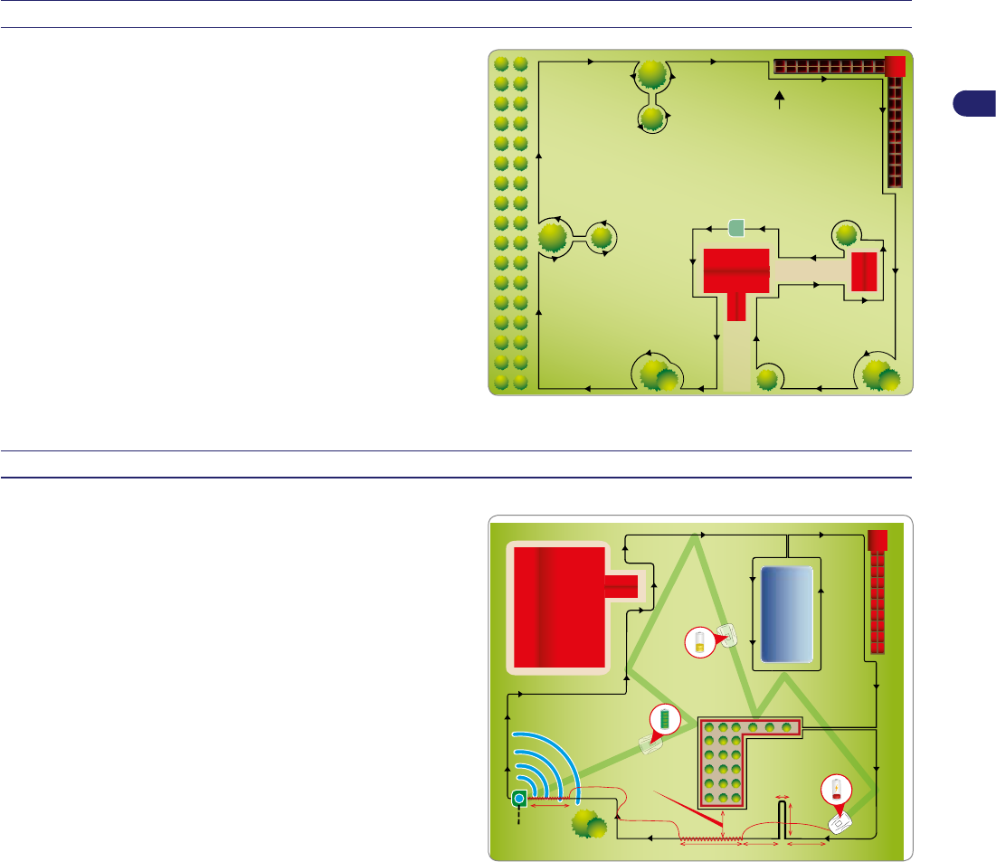
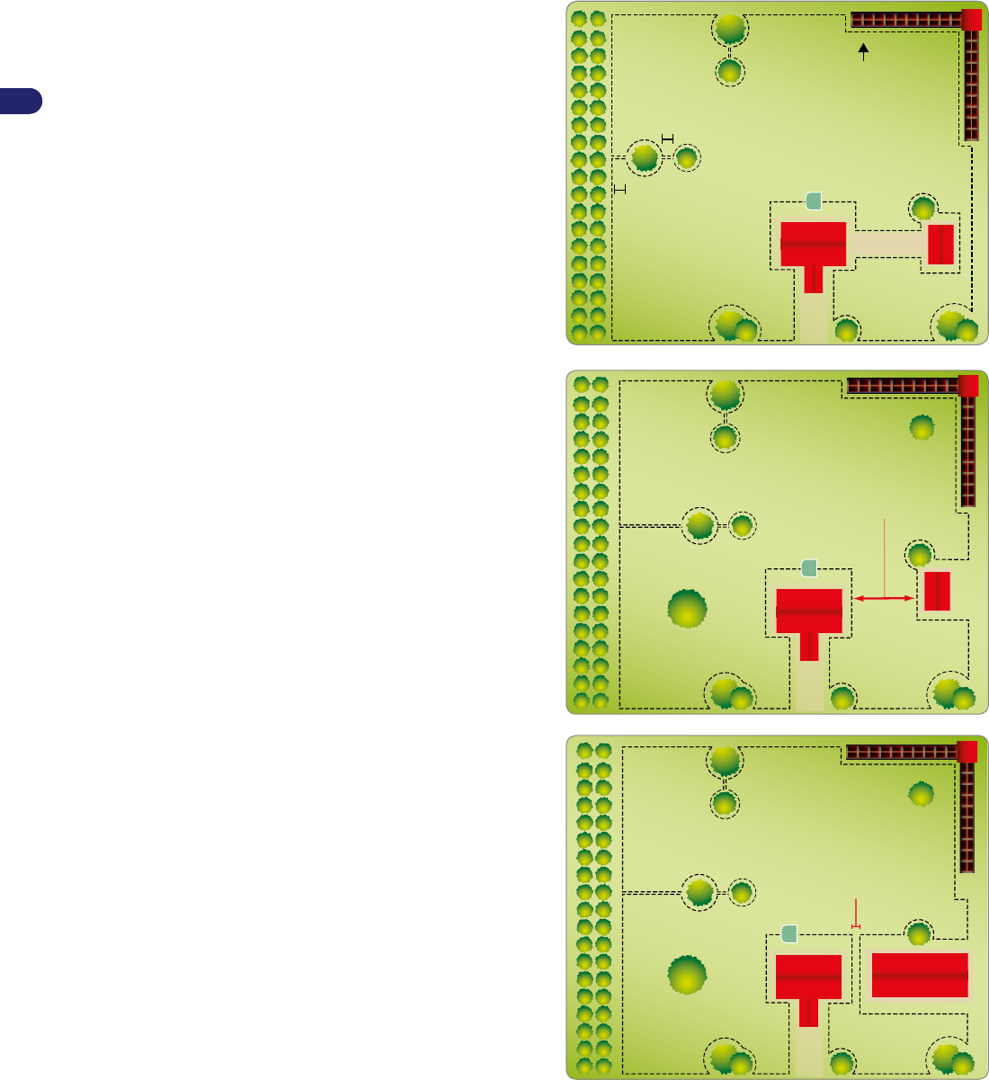
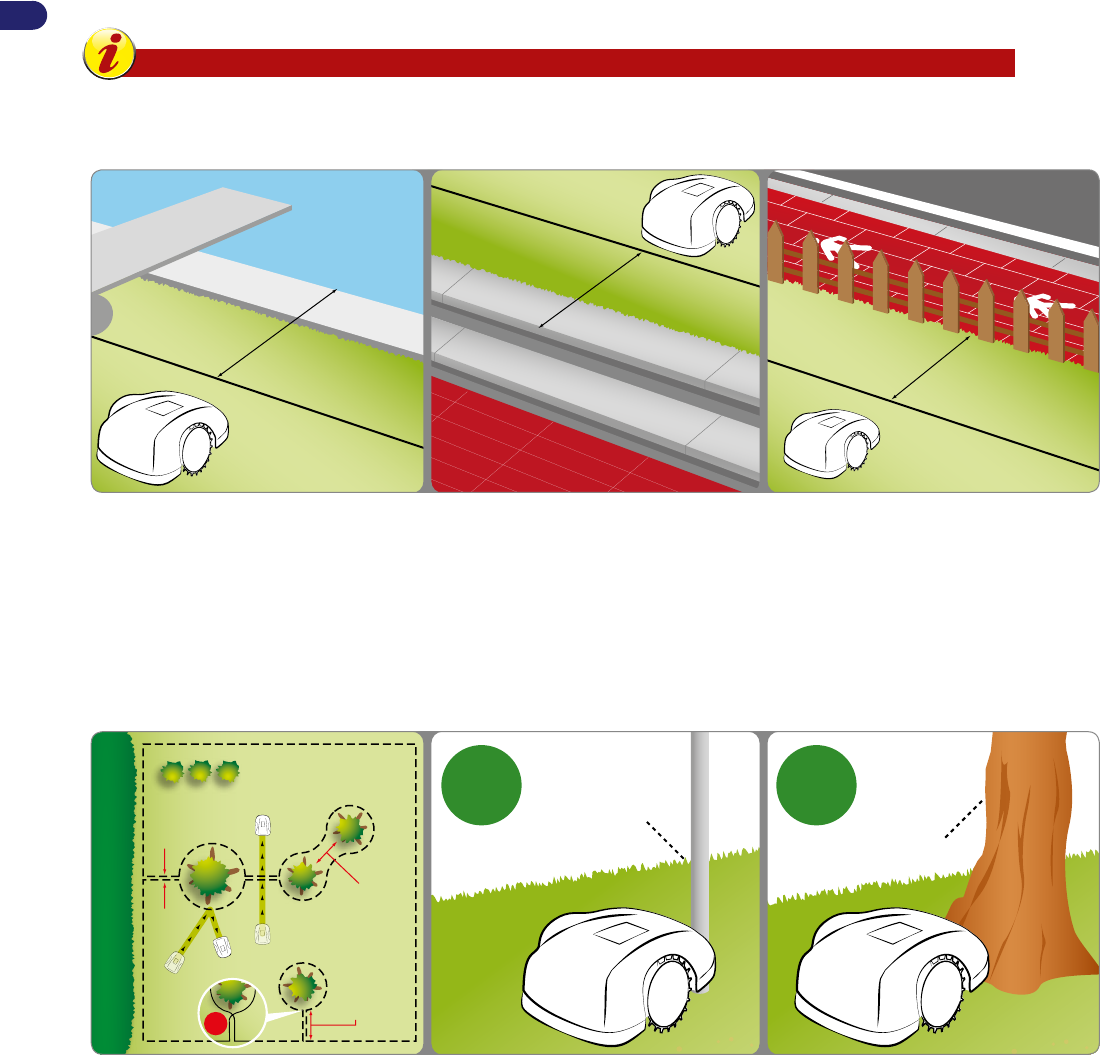
Preparation and marking the boundaries of the work areas. .................................................................................................... 13
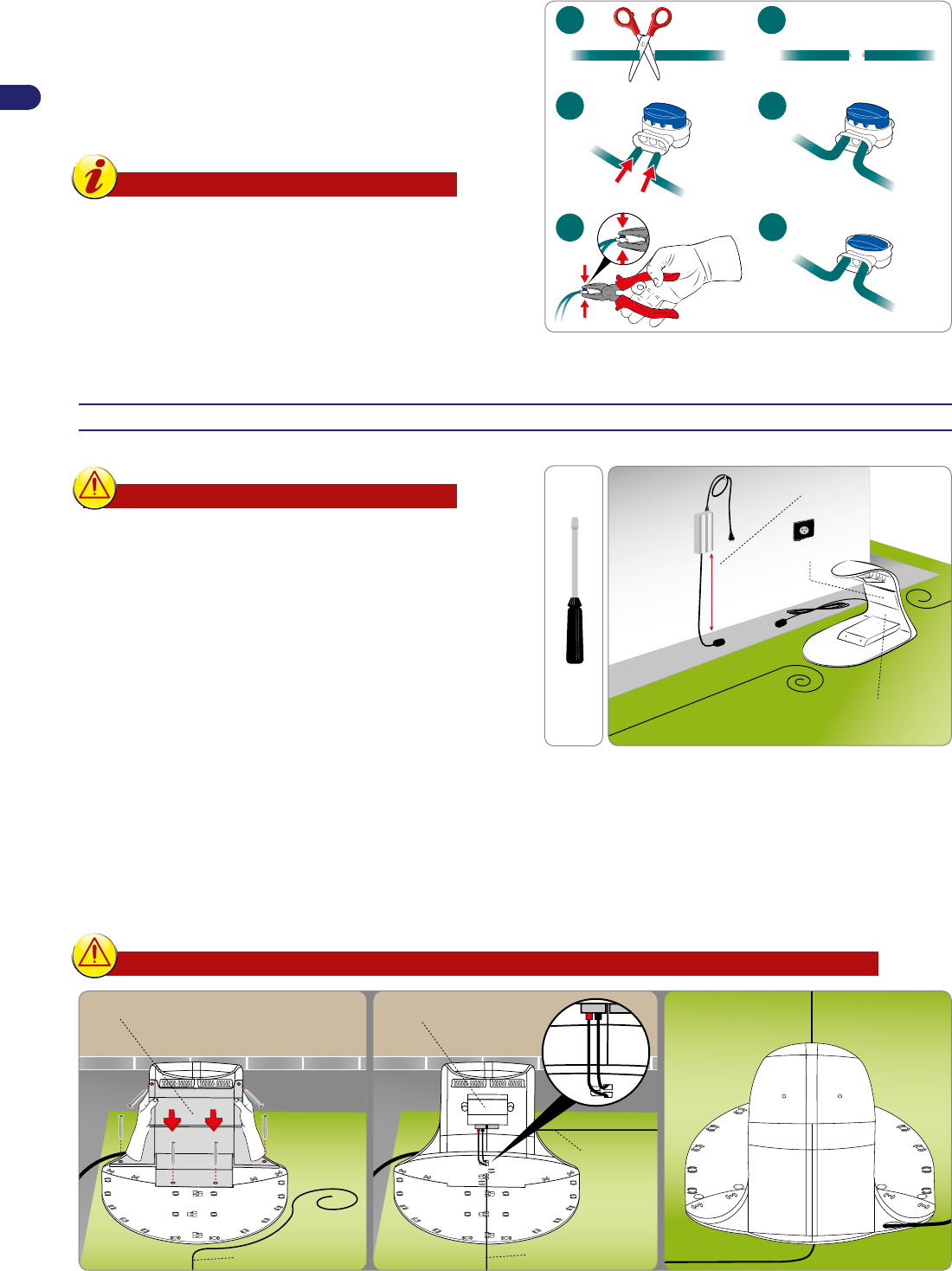
Installation of perimeter wire. ....................................................................................................................................................17
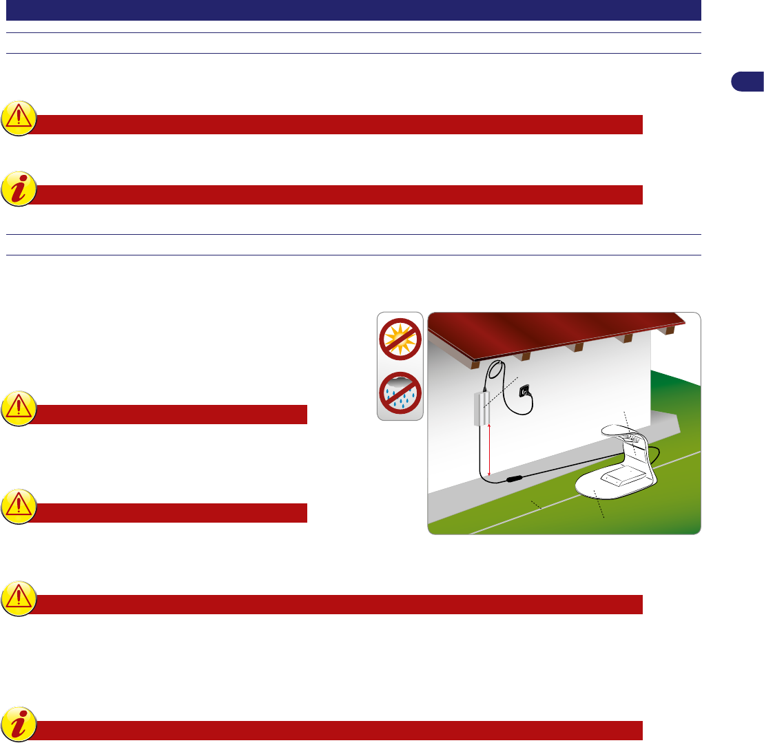
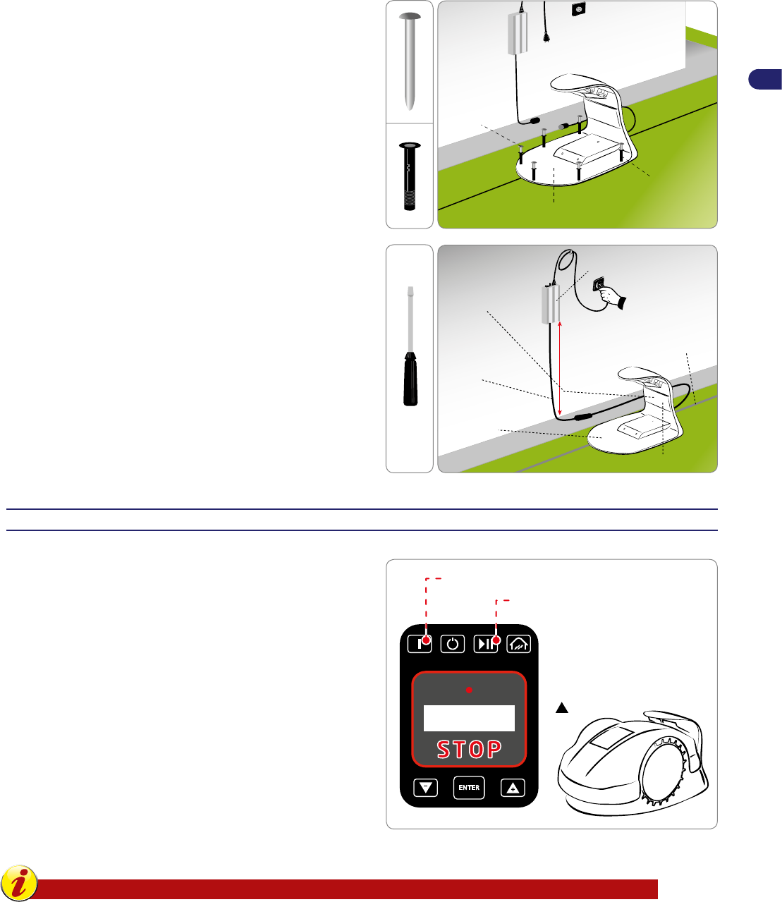
Installation of the charging station and power supply unit.........................................................................................................18
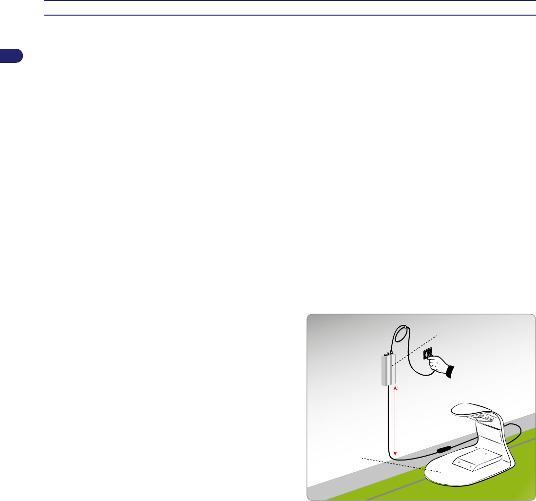
Battery charging on rst use. .................................................................................................................................................... 19
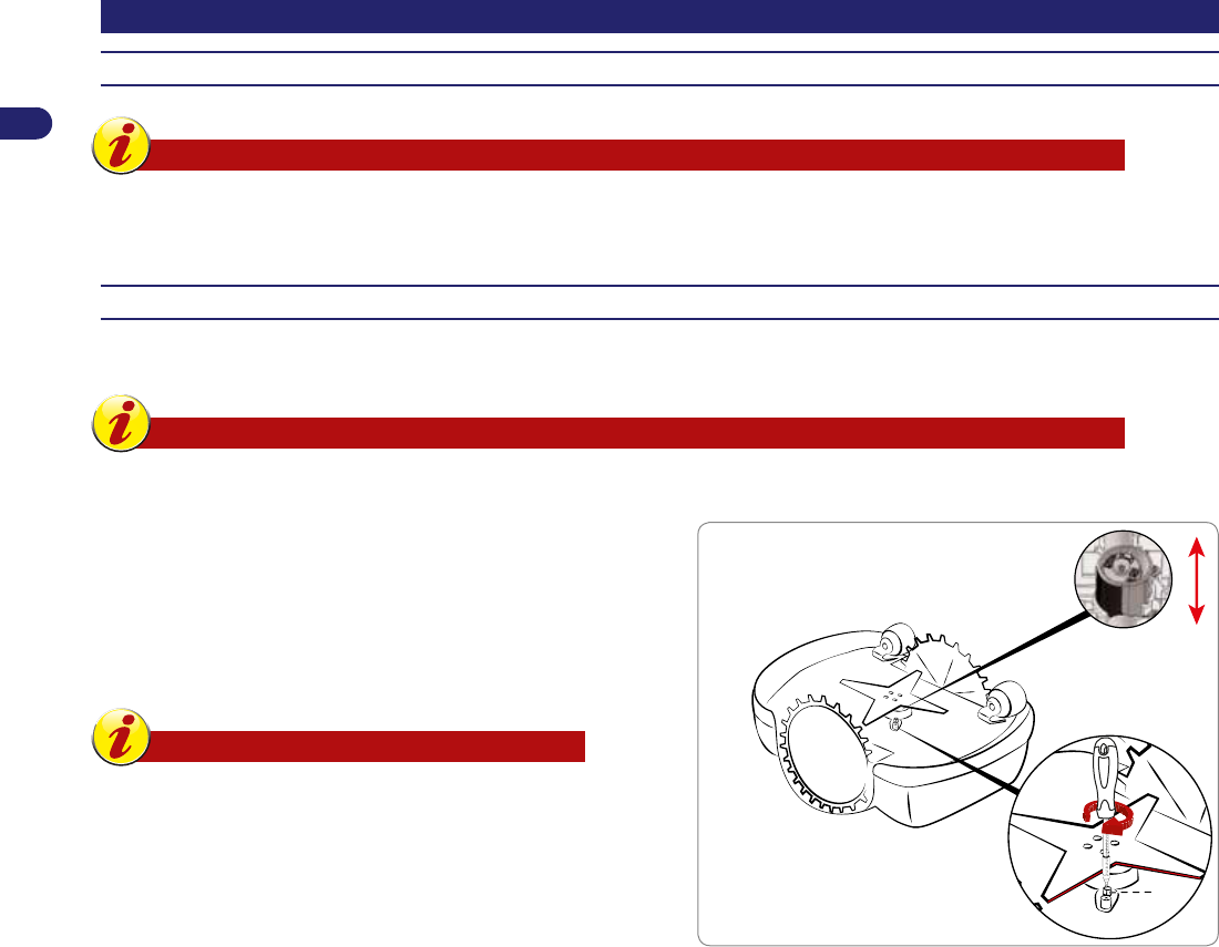
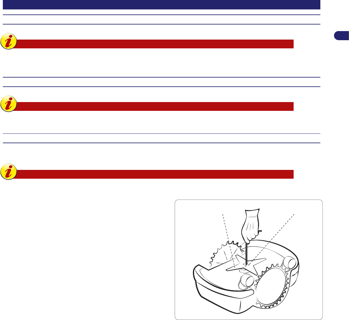
Adjustment of cutting height. .....................................................................................................................................................20
Use and operation. .................................................................................................................................................................... 21
Obligations for use. ................................................................................................................................................................... 21
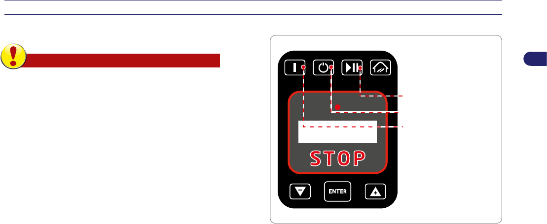
Description of robot commands. ............................................................................................................................................... 21
Menu access. ............................................................................................................................................................................21
Automatic return to the charging station. .................................................................................................................................. 28
Use of the robot in closed areas with no charging station.........................................................................................................28
Visualising the display during the work phase. .........................................................................................................................29
Prolonged inactivity and restarting. ...........................................................................................................................................30
Battery charging after prolonged inactivity. ............................................................................................................................... 31
Part replacement. ......................................................................................................................................................................37
Recommendations for replacing parts. ..................................................................................................................................... 37
EC declaration of conformity. ...................................................................................................................................................39
Reproduction, even partial, of this document without written permission by the manufacturer is strictly forbidden. The
manufacturer assumes a policy of continual improvement and reserves the right to modify this document without prior notice
on condition that the changes do not constitute health and safety risks.
Libble takes abuse of its services very seriously. We're committed to dealing with such abuse according to the laws in your country of residence. When you submit a report, we'll investigate it and take the appropriate action. We'll get back to you only if we require additional details or have more information to share.
Product:
Forumrules
To achieve meaningful questions, we apply the following rules:
First, read the manual;
Check if your question has been asked previously;
Try to ask your question as clearly as possible;
Did you already try to solve the problem? Please mention this;
Is your problem solved by a visitor then let him/her know in this forum;
To give a response to a question or answer, do not use this form but click on the button 'reply to this question';
Your question will be posted here and emailed to our subscribers. Therefore, avoid filling in personal details.
Register
Register getting emails for Ambrogio L85 Evolution at:
new questions and answers
new manuals
You will receive an email to register for one or both of the options.
Get your user manual by e-mail
Enter your email address to receive the manual of Ambrogio L85 Evolution in the language / languages: English as an attachment in your email.
The manual is 5,82 mb in size.
You will receive the manual in your email within minutes. If you have not received an email, then probably have entered the wrong email address or your mailbox is too full. In addition, it may be that your ISP may have a maximum size for emails to receive.
If you have not received an email with the manual within fifteen minutes, it may be that you have a entered a wrong email address or that your ISP has set a maximum size to receive email that is smaller than the size of the manual.
The email address you have provided is not correct.
Please check the email address and correct it.
Your question is posted on this page
Would you like to receive an email when new answers and questions are posted? Please enter your email address.