483701
23
Zoom out
Zoom in
Previous page
1/24
Next page
1
AA 05
Digital DVB-T Zimmerantenne
Die aktive Zimmerantenne AA 05 wurde
speziell zum Empfang von digitalen
terrestrischen TV- und Radio-Programmen
(DVB-T, DAB) im
VHF-/UHF-Empfangsbereich für den
Innenbereich (mit ausreichendem
Signalpegel) entwickelt.
Das flache platzsparende Design im
Silber-Metallic-Look passt sich ideal zu
aktuellen Fernsehgeräten und in moderne
Zimmereinrichtungen ein.
Merkmale
Aktive Antenne mit Verstärker
Variabel für horizontale, vertikale Aufstellung oder für die Wandmontage
Kompletter VHF/UHF-Breitband-Empfangsfrequenzbereich 47 – 860 MHz
(Kanal 02 bis 69)
geringes Rauschmaß, dank hochwertiger Schaltungstechnik
Schutzfilter gegen GSM-Störungen
Zwei-Wege-Stromversorgung, wählbar zwischen mitgeliefertem ext.
Steckernetzteil oder per Fernspeisung vom DVB-T Receiver
Lieferumfang
Antenne AA 05
Stützfuß zum Aufstellen
oder Aufhängen
Schrauben zur Wandbefestigung
2m Koax-Antennen-Anschlußkabel F-Stecker auf DIN-Stecker
Steckernetzteil 12V DC/250mA
2
Aufstellungshinweise
Betreiben Sie das Gerät nur in trockenen Innenräumen.
Am besten sind Räume mit Fenstern nach Außen, die somit bessere
Empfangsbedingungen für einen ausreichenden Signalpegel haben.
Setzen Sie das Gerät nicht über längeren Zeitraum direkter
Sonneneinstrahlung aus, da sich Materialveränderungen ergeben können.
Stellen Sie die Antenne nicht in die Nähe von Heizungen oder offenem Feuer
(z.B. Kerze): Brandgefahr!
Das Gerät sollte auf einem sicheren, festen Untergrund aufgestellt werden.
Der Standort darf nicht in Räumen mit hoher Luftfeuchtigkeit gewählt
werden, da Kondenswasserniederschläge zu Fehlfunktionen oder
Beschädigungen führen.
Vermeiden Sie den Kontakt des Gerätes mit Wasser, Flüssigkeiten oder
Feuchtigkeit. Nehmen Sie das Gerät nicht in der Nähe von Badewannen
oder Swimmingpools in Betrieb.
Reinigung
Ziehen Sie den Netzstecker, bevor Sie das Gerät reinigen. Benutzen Sie zur
Reinigung ein trockenes oder leicht angefeuchtetes Tuch.
Antenne Standfuß Wandbefestigung Koaxial Kabel Steckernetzteil
3
Betriebshinweise
In Gebieten mit geringen oder zu starken Empfangsfeldstärken ist ein
störungsfreier Empfang nicht in allen Fällen gewährleistet. Bei zu
schwachem Signalpegel sollte eine Richtantenne außerhalb des Gebäudes
verwendet werden.
In unmittelbarer Nähe zum Sender kann der Empfang durch zu hohe
Empfangspegel beeinträchtigt werden. Dann sollte eine fensternahe
Aufstellung vermieden werden.
Der Rundfunkempfang in Innenräumen kann zudem durch weitere Faktoren
beeinträchtigt werden:
- Räume in Stahlbetonbauten
- Räume mit metallbedampften Fenstern
- in unmittelbarer Nähe von sendenden elektr. Geräten (z.B. Mobiltelefonen)
Inbetriebnahme (siehe Anschlussskizze nebenan)
Schritt 1: Verbinden Sie die Antenne über das mitgelieferte Antennenkabel mit
dem DVB-T Receiver.
Achtung! Nicht an einen Sat-Receiver anschließen!
Schritt 2: Verbinden Sie das mitgelieferte Steckernetzteil mit der Antennenbuchse
auf der Geräterückseite und stecken Sie es anschließend in die 230V
Wandsteckdose.
Hinweis:
Wenn Ihr DVB-T Receiver über eine
5-Volt-Fernspeisemöglichkeit über den Antenneneingang verfügt
(z.B. Zehnder DVB-T-Box), dann benötigen Sie Schritt 3 und somit
das Steckernetzteil nicht
Schritt 3: Stecken Sie den Stützfuß in das auf der Geräterückseite vorgesehene
Loch. Je nach Aufstellungsposition (vertikal oder horizontal) sollte zuvor
die Einsteckvorrichtung am Gehäuse gedreht werden.
Schritt 4: Verbinden Sie den Receiver mit dem TV-Gerät (siehe
Receiver-Handbuch) und schalten Sie beide Geräte ein.
Hinweis:
Bei Verwendung des Receivers mit 5V-Fernspeisung
(siehe unter 3.) müssen Sie über das Einstellmenü des Receivers
sicherstellen, dass die 5V Stromversorgung der Antenne über das
Antennenkabel eingeschaltet ist (siehe Receiver-Handbuch).
4
Tipps zur Ausrichtung der Antenne
Zur Beurteilung der Empfangsqualität kann sowohl das
Fernsehbild, als auch die Signalpegel-/qualitätsanzeige im
Einstellmenü des Receivers herangezogen werden.
Sollte der Empfang gestört sein, drehen Sie die Antenne
leicht oder wechseln Sie durch seitliches Kippen
(horizontal – vertikal) die Polarisationsausrichtung und
kontrollieren Sie die Empfangsqualität.
Sollte kein optimaler Empfang möglich sein, stellen Sie die
Antenne an einem anderen Ort auf (Empfehlung:
Fensternähe) und wiederholen Sie die Prozedur.
Auch bei einer Installation an der Wand sollte zuvor durch Verändern der
Position an der Wand oder im Raum die Empfangsqualität überprüft werden.
Anschlüsse:
AA 05 Rückseite
Schritt 1:
Antennenkabel 5V/40mA
Schritt 4:
SCART-
KABEL
TV
Schritt 3:
Stützfuß
DVB-T Receiver
Schritt 2:
230V
Steckdose
9-12V DC
Versorgungsanschluss
5
Wandmontage (siehe Skizze)
1. Nach Herausfinden der günstigsten Stelle an der Wand markieren Sie mit
einem Bleistift die 2 Positionen der zu bohrenden Schraubenlöcher zur
Befestigung des Standfußes.
2. Bohren Sie mit einem 5,8mm-Bohrer die zwei Löcher auf eine Tiefe von
ungefähr 35mm in die Wand. (Bei Befestigung auf einem Holzuntergrund
benötigen Sie keine Bohrungen und Dübel)
3. Schlagen Sie mit einem Hammer die beiden Dübel in die Bohrungen ein.
4. Drehen Sie die Schrauben mit Hilfe eines Schraubendrehers nur soweit in
die Bohrungen hinein, damit Sie den Standfuß noch bequem einhängen
können. Lassen Sie die Schrauben ca. 10mm von der Wand herausstehen.
5. Verbinden Sie die Kabel mit der Antenne und hängen sie mit dem Standfuß
an den zwei Schrauben ein.
6
Technische Daten:
Frequenzbereich
VHF 47~230MHz, Kanal 02~12
UHF 470~860MHz, Kanal 21~69
Verstärkung 21 ±3 dB
Stromversorgung 1.
oder
2.
230V AC/100mA, mit Netzteil,<0,9W
5V DC/40mA, von Receiver, <0,2W
Steckernetzteil
Verbrauch
AC ~230V/50Hz; DC 12V/250mA
<0,4W (Nullast), <0,9W (Betrieb)
Gewicht ~210 g
Größe: B x H x T (mm) 139 x 209 x 23
HEINRICH ZEHNDER GMBH Telefon: 07729/881-0
Weierhalden 37/1 FAX: 07729/881-72
D-78144 Schramberg/Germany info@zehnder-sat.de
http://www.zehnder-sat.de
Dieses Produkt ist mit einer Energiesparschaltung nach
der EU Verordnung 278/2009 für externe Netzteile und
nach der Richtlinie 2005/32/EG zur umweltgerechten
Gestaltung energiebetriebener Produkte ausgestattet
(Ökodesign-Anforderungen).
Entsorgung
Elektronische Geräte gehören nicht in den Hausmüll, sondern
müssen gemäß der RICHTLINIE 2002/96/EG DES EURO-
PÄISCHEN PARLAMENTS UND DES RATES vom 27. Januar
2003 über Elektro- und Elektronik-Altgeräte fachgerecht entsorgt werden.
„Bitte geben Sie dieses Gerät am Ende seiner Verwendung zur Entsorgung
an den dafür vorgesehenen öffentlichen Sammelstellen ab."
7
AA 05
Digital Indoor Antenna
AA 05 was specially designed to receive
digital terrestrial TV signal as well as radio
programs (DVB-T, DAB) in the VHF- and UHF-
frequency range at indoor use.
The metal-silver, flat and stylish housing is
a perfect match for your modern TV set and
your modern styling living room.
Features
Active antenna with embedded amplifier
Friendly Advanced design for either Horizontal or Vertical position
For Desktop or wall mounting installation
complete VHF/UHF wide band range reception 47-860 MHz (CH 02-69)
Low noise figure by using high-quality components
Built-in filter against GSM signal interference
Convenient Powering System – two ways selectable either with power adaptor
or with DVB-T receiver
Accessories attached :
1) Antenna AA 05
2) Foot for standing or wall mounting
3) Wall mounting kit
4) F-connector to IEC-connector antenna coaxial cable, 2m
5) Power adaptor 12VDC/250mA
8
Location and Installation Notes:
Operate the antenna only at dry indoor places.
Rooms with windows are the most suitable locations to get best reception
quality with sufficiently high signal level.
Do not subject it to direct sunlight for longer periods, because material can
change for the worse.
Do not place the antenna close to heaters or naked lights (e.g. candles).
There might be a danger of fire!
Place the antenna on a safe and firm ground.
Protect the device from moisture, drips and splashes.
Cleaning
Before cleaning, unplug the antenna from power and antenna cable.
Use only a soft and slightly moistened cloth to clean the casing.
Main Unit Standing Unit Wall Mounting Coaxial Cable AC Adaptor
9
Operation Notes:
In areas with low or too high reception-field strength, interference-free
reception is not always guaranteed. If the signal level is too low, a directional
antenna should be placed outside the building.
In the immediate vicinity of the transmitter, reception may be impaired by a
too high reception level. In this case, you should avoid setting up the antenna
near a window.
Indoor radio reception can also be impaired by other factors:
- rooms in reinforced concrete buildings
- rooms with vapour-plated windows
- in positions directly beside transmitting electronic devices (e.g. mobile
phones)
Installation (Please refer to illustration):
Step 1. Take the IEC cable attached, and then connect one end to the IEC port,
and the other end to your DVB-T receiver shown in illustration
Attention! Don´t connect to a Satellite-Receiver!
Step 2. Take the power adaptor attached and Insert the end of DC connector into
DC jack on the back of AA 05, and then plug in the A/C end.
***** If your DVB-T receiver (e.g. from Zehnder) supplies with 5 VDC from
IEC connector, then it is not necessary to use the power adaptor.
Step 3. Take the standing unit attached , and then plug into the hole shown in
illustration to keep it standing. Before, check the position of rotating hole
for either vertical or horizontal direction.
Step 4. Connect your receiver and your TV by Scart Cable (see receiver manual)
and switch them on.
***** If your DVB-T receiver supplies with 5 VDC, ensure in the set-up menu
of the receiver, that the power supply to the antenna via the coax cable
is switched on.
10
Tips for correct Antenna Adjustment
To verify the quality of reception, you can use either the TV
picture or the option of displaying the reception level and
signal quality in the set-up menu of your receiver.
If reception is subject to interference, turn the antenna
slightly, or alter the direction of polarisation by titling it
sideways (horizontal – vertical), and check the quality of
reception.
If it is impossible to get optimum reception, set the antenna
up in a different place (we recommend a position close to a
window), and repeat the steps described above.
Even for wall mounting installation, before you should check antenna position
at the wall and in the room for best possible reception quality.
Connecting Illustration
AA 05 Rear View
Step 1.:
F to IEC RF Cable
Step 4. :
SCART
CABLE
TV
Step 3. :
Standing Unit
DVB-T Receiver Rear View
To AC
Outlet
Step 2. :
9-12V DC Power
11
Wall mounting installation (see sketch)
1. After you found the best location to place the antenna at the wall, mark with
a pencil the 2 positions for the wholes to fix the standing unit.
2. Drill with a 5,8mm-drill the two wholes into the depth of about 35mm. (If you
install to a wooden wall you do not need to drill and use the plastic poles)
3. Hammer the two plastic poles with a hammer into the wholes.
4. Screw the screws with a screwdriver into the plastic pole as far as you still
easily can hook the standing unit of the antenna. Leave the screws about
10mm out of the wall.
5. Connect all cables and hook the antenna onto the screws.
12
HEINRICH ZEHNDER GMBH Telefon: 07729/881-0
Weierhalden 37/1 FAX: 07729/881-72
D-78144 Schramberg/Germany info@zehnder-sat.de
http://www.zehnder-sat.de
Specifications:
Frequency Range
V
HF 47~230MHz, CH 02~12
UHF 470~860MHz, CH 21~69,
A
mplifier Gain 21 ±3
dB
Two Powering selection
with adaptor 230
V
/100mA, <0,9
W
with DVB-T receiver 5V/40mA, <0,2W
(center "+", outer"-")
Power adaptor
consumption
A
C ~230V/50Hz; DC 12
V
/250mA
<0,4W (no-load), <0,9W (operation)
Weight ~210g
Size: L x W x H (mm)
139 x 209 x 23
Disposal
Electronic equipment is not household waste. In accordance with
directive 2002/96/EC OF THE EUROPEAN PARLIAMENT AND
THE COUNCIL of 27th January 2003 on used electrical and
electronic equipment, it must be disposed of properly.
„At the end of its service life, take this unit for disposal at the designated
p
ublic collection
p
oints."
This product is developed accordingly to the European regulation 278/2009 for
external power supplies and directive 2005/32/EG with regard to ecodesign
requirements.
13
AA 05
Antenne digitale d'intérieur
L'antenne ITA 6000 TNT a été conçue pour
recevoir le signal de télévision numérique
terrestre (TNT) ainsi que les programmes des
radios (si diffusées) sur les bandes VHF et UHF.
Le boîtier argenté, plat et élégant s'intégrera
parfaitement avec votre ensemble de télévision.
Dispositifs
Antenne active avec l'amplificateur incorporé.
Conception évoluée pour utilisation horizontale ou verticale.
Pour mise sur pied ou montage mural
Réception 47-860 MHz (canaux 02-69) des bandes VHF/UHF.
Filtre intégré contre l'interférence des signaux GSM.
Deux alimentations sélectionnables : bloc secteur fourni ou adaptateur TNT.
Eléments fournis :
Antenne AA 05
Pied de support pour poser ou accrocher au mur
Kit pour fixation murale
Prolongateur coaxial d'antenne équipé de connecteurs Ø 9,5 mm (2 mètres
environ)
Bloc secteur : 230 V - 12 VDC/250 mA
14
Notes sur l'emplacement et l'installation :
Placez l'antenne dans un endroit à l'abri de toute humidité.
Les pièces avec des fenêtres sont les endroits les plus appropriés pour obtenir la
meilleure qualité de réception avec un niveau de signal suffisamment élevé.
N'exposez pas l'antenne à la lumière directe du soleil de manière prolongée, le matériel
peut se détériorer.
Ne placez pas l'antenne près de chauffage ou d'une source de chaleur nue (par
exemple bougies). Il pourrait y avoir un risque d'incendie.
Placez l'antenne sur un meuble stable.
Utilisez exclusivement le bloc secteur fourni, raccordez celui-ci sur le secteur
conformément aux indications portées sur l'étiquette d'identification apposée sur
celui-ci (tension, courant, fréquence du réseau électrique). Par précaution, en
cas de danger, les adaptateurs secteur servent de dispositif de sectionnement
de l'alimentation 230 V. Ils doivent être situés à proximité de l'appareil et être
aisément accessibles.
Nettoyage
Avant le nettoyage, débranchez le bloc secteur et le prolongateur coaxial.
Employez seulement un chiffon doux légèrement humidifié pour nettoyer le boîtier.
Antenne AA 05 Pied de support Kit pour fixation Prolongateur coaxial Bloc
murale secteur
15
Notes d'information
Dans les zones ayant un niveau de réception trop faible ou trop élevé, la
réception sans interférence n'est pas toujours garantie. Si le niveau de
réception du signal est trop bas, une antenne de toit large bande devrait être
placée en dehors du bâtiment.
A proximité immédiate d'un émetteur, la réception peut être altérée par un
niveau trop élevé de réception. Dans ce cas, vous devez éviter d'installer
l'antenne près d'une fenêtre.
La réception radio peut également être altérée par les facteurs suivants : -
pièces avec des structures en béton armé,
- pièces à haute isolation (thermique, phonique, etc..),
- à proximité d'un équipement à transmission radio (par ex : téléphone
portable, téléphone domestique sans fil, etc..).
Installation (référez-vous au schéma de raccordement):
Etape 1: Prenez le prolongateur d'antenne, reliez l'extrémité coudée sur l'antenne et
l'autre sur votre adaptateur TNT comme indiqué sur le schéma (page
4).
Attention : ne reliez en aucun cas à un adaptateur satellite.
Attention : si votre l'adaptateur TNT fourni le 5 volts continu par le
prolongateur coaxial, alors il n'est pas nécessaire d'utiliser le bloc
secteur, ne réalisez pas l'étape 4.
Etape 2 : Reliez votre adaptateur TNT et votre Téléviseur à l'aide du câble péritel
(cordon non fourni).
Etape 3 : Prenez le support et placez-le dans le trou comme indiqué sur le sché
ma (page 4).
Etape 4 : Raccordez le câble du bloc d'alimentation sur l'arrière de l'antenne, puis
connectez le bloc au secteur.
16
Ajustement de l'antenne
Pour vérifier la qualité de la réception, vous pouvez vous aider
de l'affichage de niveau de réception fourni par votre
adaptateur TNT (voir le menu d'installation de votre l'adaptateur
TNT en vous reportant au guide d'utilisation).
Si la réception est sujette à des interférences, tournez
légèrement l'antenne ou changez la direction de polarisation
(horizontale/verticale) en orientant l'antenne et vérifiez la qualité de
la réception.
S'il est impossible d'obtenir une réception optimale, déplacez
votre antenne et installez-la en hauteur ou près d'une fenêtre.
Répétez les étapes ci-dessus jusqu'à obtenir une réception satisfaisante.
Même pour une installation murale, il est souhaitable de tester la position
d’antenne au mur et dans la pièce pour assurer la meilleure qualité de
réception.
Connecting Illustration
AA 05 - Vue arrière
Etape 1.:
Prolongateur coaxial
Etape 4. :
Câble PERITEL
TV
Etape 3. :
Support
Adapteur TNT - Vue
arrière
Bloc
Secteurt
Etape 2. :
Alimentation 9-12V CC
17
Montage mural (voir croquis)
1. Après avoir trouvé le meilleur emplacement mural, marquez à l’aide d’un
crayon les 2 positions des trous à perforer pour fixer le pied de support.
2. Perforez les deux trous sur une profondeur d’environ 35 mm avec une
mèche de 5.8 mm dans le mur. ( sur un mur en bois , ni des perçages, ni
de chevilles sont nécessaires)
3. Enfoncez les deux chevilles dans les trous .
4. Visser les vis dans les chevilles de manière à pouvoir accrocher facilement
le pied de support de l’antenne. Laissez dépasser les vis d’environ 10 mm
du mur .
5. Branchez les câbles à l’antenne et accrochez la.
18
HEINRICH ZEHNDER GMBH Telefon: 07729/881-0
Weierhalden 37/1 FAX: 07729/881-72
D-78144 Schramberg/Germany info@zehnder-sat.de
http://www.zehnder-sat.de
Spécifications :
Plage des fréquences
VHF 47~230MHz, Canaux 02~12
UHF 470~860MHz, Canaux 21~69,
Gain 21 ±3 dB
Deux alimentations
avec bloc seteur 230V/100mA, <0,9W
avec récepteur TNT 5V/40mA, <0,2W
(coaxial : âme "+", tresse "-")
Bloc secteur
A
C ~230V/50Hz; DC 12
V
/250mA
<0,4W (no-load), <0,9W (operation)
Poids ~210g
Taille : L x W x H (mm) 139 x 209 x 23
Elimination
Les appareils électroniques ne font pas partie des déchets
domestiques et doivent à ce titre, conformément au règlement
2002/96/CEE du PARLEMENT EUROPÉEN ET DU CONSEIL
du 27 janvier 2003 portant sur les déchets d’équipements
électriques et électroniques, être éliminés comme il se doit.
„Veuillez remettre cet appareil, lorsqu’il sera hors d’usage, dans un point de
collecte officiel spécialement prévu à cet effet."
19
AA 05
Antenna digitale interna
AA 05 è stata progettata per ricevere i segnali
TV digitali terrestri e i programmi radio,
nelle gamme di frequenza VHF e UHF,
con installazione interna L’involucro piatto
ed elegante, in metallo color argento, si adatta
perfettamente al vostro moderno televisore e
allo stile moderno del vostro soggiorno.
Caratteristiche
Antenna attiva con amplificatore incorporato
Concezione evoluta per utilizzo sia in verticale che in orizzontale
Può essere utilizzata sia da tavolo che fissata alla parete
Ricezione in banda larga VHF-UHF 47-860 MHz (CH 02-69)
I componenti di alta qualità garantiscono immagini poco disturbate
Filtro incorporato contro le interferenze dei segnali GSM
Comodo sistema di alimentazione - è possibile selezionare l’alimentatore
o il ricevitore DVB-T
Accessori in dotazione
1) Antenna AA 05
2) Supporto per utilizzo su ripiano o montaggio a parete
3) Kit per il montaggio a parete
4) Cavo coassiale (2 metri) d’antenna con connettori IEC e F
5) Alimentatore
12VCC/250mA
20
Note riguardanti posizione e installazione
Utilizzare l’antenna solo in ambienti non umidi
Le stanze con finestre sono gli ambienti più adatti per ottenere una qualità
ottimale di ricezione con un livello sufficientemente alto di segnale.
Fate attenzione a non esporre l’unità alla luce diretta del sole per lunghi
periodi. Il materiale può deteriorarsi
Non mettere l’antenna vicino a fonti di calore o, per esempio, candele
accese. C’è pericolo d’incendio!
Mettere l’antenna in posizione stabile e sicura
Proteggere l’unità da vapore, umidità, spruzzi
Pulizia
Prima di pulire l’unità, scollegarla dalla presa di rete e dal cavo coassiale.
Utilizzare solo un panno morbido, eventualmente leggermente inumidito, per
pulire l’involucro esterno.
Unità principale Supporto Tassello Cavo coassiale Adattatore CA
21
Note riguardanti il funzionamento
Nelle zone con livello di ricezione troppo basso o troppo altro, non è sempre
garantita la ricezione priva di disturbi. Se il livello del segnale è troppo basso,
vi consigliamo d’installare un’antenna sul tetto
Nelle immediate vicinanze del trasmettitore, la ricezione potrebbe essere
alterata da un livello troppo alto di ricezione. In questo caso non installate la
vostra antenna vicino a una finestra.
La ricezione radio interna può venire alterata anche da altri fattori:
- stanze all’interno di edifici in cemento armato
- stanze ad alto isolamento (termico, acustico, ecc)
- In posizioni in prossimità di apparecchiature elettroniche
(per esempio telefoni mobili, cordless, ecc.)
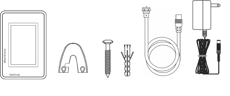
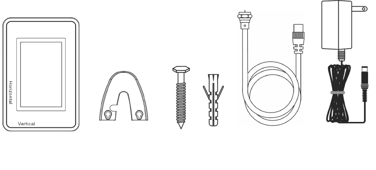
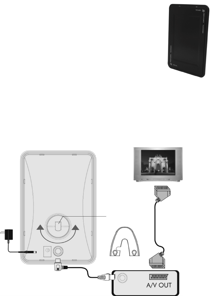
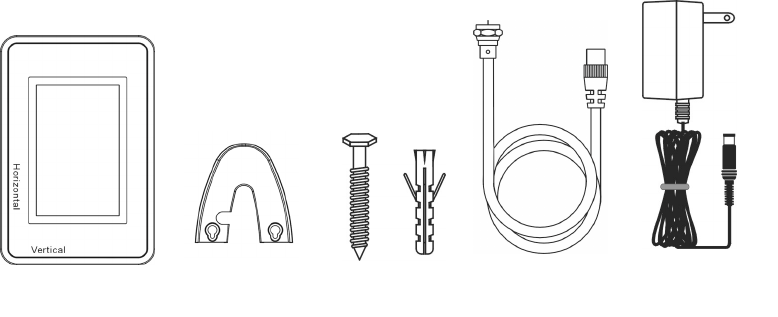
Installazione (riferitevi alle immagini)
Punto 1. prendere il cavo coassiale IEC e collegare un’estremità alla porta IEC e
l’altra al vostro ricevitore DVB-T, come da illustrazione
Attenzione! Non collegare l’unità a un Ricevitore Satellitare!
Punto 2.
collegare l’adattatore alla presa DC posta sul retro dell’unità AA 05 e
l’altra estremità alla presa CA.
Se il vostro ricevitore DVB-T (per esempio Zehnder TX 250) fornisce
5V CC dal connettore IEC, non è necessario utilizzare l’adattatore
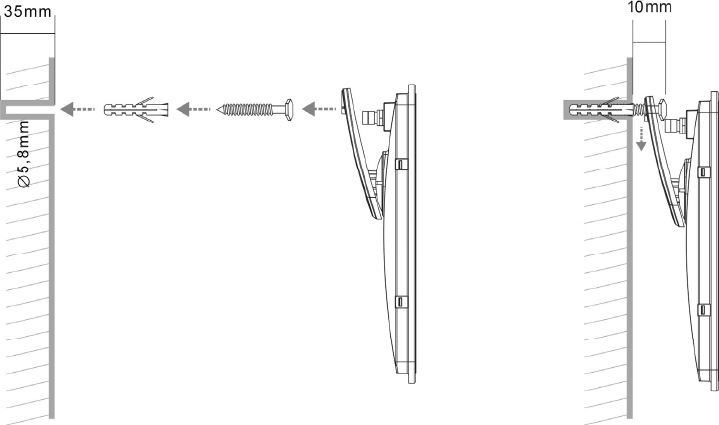
Punto 3. inserire il supporto come mostrato nella figura, dopo aver scelto la
direzione verticale o orizzontale
Punto 4. collegare ricevitore e TV con il Cavo Scart (riferirsi al manuale d’uso del
ricevitore) e quindi accendere entrambi gli apparecchi
Se il vostro ricevitore DVB-T fornisce 5V CC, assicuratevi nel menù
d’impostazione del ricevitore che l’alimentazione all’antenna via
cavo coassiale sia accesa.
22
Retro dell’AA 05
Consigli per una corretta regolazione dell’antenna
Per verificare la qualità di ricezione, potete utilizzare
sia l’immagine TV che l’opzione di visualizzazione del
livello di ricezione e la qualità del segnale nel menù
d’impostazione del vostro ricevitore.
Se la ricezione è soggetta a interferenze, ruotate
leggermente l’antenna o inclinatela (verticale –
orizzontale) e controllate la qualità di ricezione.
Se non riuscite ad ottenere una ricezione ottimale,
spostate l’antenna, mettendola più in alto o vicino a
una finestra e poi ripetete i punti precedenti.
Anche per l’installazione a parete, vi consigliamo di testare la posizione
dell’antenna sul muro e nella stanza per assicurare una qualità di ricezione
ottimale.
Collegamenti
Punto 1.:
Cavo Coassiale
Punto 4.:
CAVO
SCART
TV
Punto 3.:
Supporto
Retro del ricevitore DVB-T
Alla presa
CA
Punto 2.:
Alimentazione
9-12V CC
23
Montaggio a parete (vedere schema)
1. Dopo aver trovato la posizione migliore per posizionare l’antenna alla
parete, segnate con una matita i due punti in cui praticare i fori per fissare il
supporto.
2. Praticate i due fori da 5,8 mm e con una profondità di 35 mm. Se la parete
è di legno, non utilizzate un trapano e servitevi di tasselli di plastica.
3. Inserite i due tasselli nei fori.
4. Avvitate le viti nei tasselli e lasciatele sporgere solo quanto basta per poter
agganciare l’antenna (circa 10 mm).
5. Collegate tutti i cavi e agganciate l’antenna sulle viti.
23


Need help? Post your question in this forum.

Forumrules


Report abuse

Libble takes abuse of its services very seriously. We're committed to dealing with such abuse according to the laws in your country of residence. When you submit a report, we'll investigate it and take the appropriate action. We'll get back to you only if we require additional details or have more information to share.

Product:

For example, Anti-Semitic content, racist content, or material that could result in a violent physical act.

For example, a credit card number, a personal identification number, or an unlisted home address. Note that email addresses and full names are not considered private information.

Forumrules

To achieve meaningful questions, we apply the following rules:

Register

Register getting emails for Zehnder AA05 Digitale antenne at:


You will receive an email to register for one or both of the options.


Get your user manual by e-mail

Enter your email address to receive the manual of Zehnder AA05 Digitale antenne in the language / languages: English, German, French, Italian as an attachment in your email.

The manual is 1,24 mb in size.


You will receive the manual in your email within minutes. If you have not received an email, then probably have entered the wrong email address or your mailbox is too full. In addition, it may be that your ISP may have a maximum size for emails to receive.

The manual is sent by email. Check your email

If you have not received an email with the manual within fifteen minutes, it may be that you have a entered a wrong email address or that your ISP has set a maximum size to receive email that is smaller than the size of the manual.

The email address you have provided is not correct.

Please check the email address and correct it.

Your question is posted on this page

Would you like to receive an email when new answers and questions are posted? Please enter your email address.


Info