MANUEL D’INSTRUCTIONS POUR L’INSTALLATION, L’EMPLOI ET L’ENTRETIEN
HANDBUCH FÜR INSTALLATION, BEDIENUNG UND WARTUNG
INSTRUCTIES VOOR MONTAGE, GEBRUIK EN ONDERHOUD
MANUAL DE INSTRUCCIONES
MANUAL DE INSTRUÇÕES
Οδηγίεςχρήσηςκαιεγκατάστασης
Campana
Exaustor
Απορροφητήρας
IT
2
2
Libretto di Istruzioni
INDICE
CONSIGLI E SUGGERIMENTI............................................................................................................................................10
USO ......................................................................................................................................................................................15
CONSEILS ET SUGGESTIONS ..........................................................................................................................................26
EMPFEHLUNGEN UND HINWEISE....................................................................................................................................34
ADVIEZEN EN SUGGESTIES.............................................................................................................................................42
CONSEJOS Y SUGERENCIAS ...........................................................................................................................................50
USO ......................................................................................................................................................................................55
CONSELHOS E SUGESTÕES............................................................................................................................................58
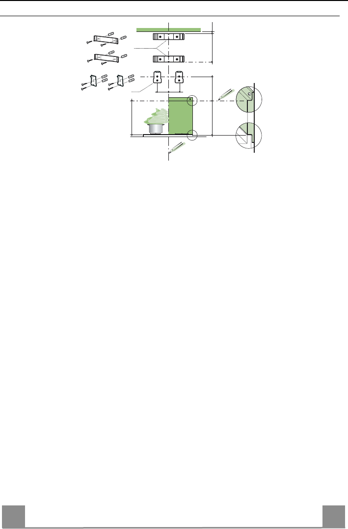
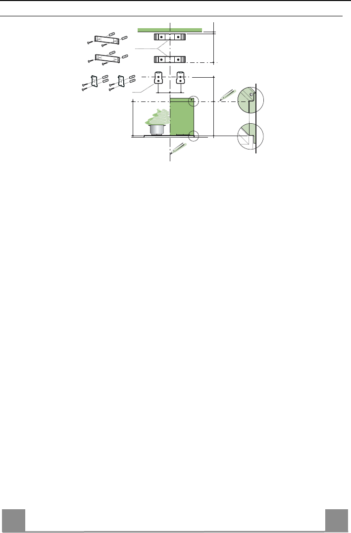
• Draw a vertical line on the supporting wall up to the ceiling, or as high as practical, at the
centre of the area in which the hood will be installed.
• Draw a horizontal line at 650 mm above the hob for installation without the back panel, or at
height H (H=height of the visible part of the panel) for installation with the back panel.
• Place bracket 7.2.1 on the wall as shown about 1-2 mm from the ceiling or upper limit align-
ing the centre (notch) with the vertical reference line.
• Mark the wall at the centres of the holes in the bracket.
• Place bracket 7.2.1 on the wall as shown at X mm below the first bracket (X = height of the
upper chimney section supplied), aligning the centre (notch) with the vertical line.
• Mark the wall at the centres of the holes in the bracket.
• Place bracket 7.1 as shown 95 mm from the vertical reference line and 210 mm above the
horizontal reference line.
• Mark the centres of the holes in the bracket.
• Repeat this operation on the other side.
REAR PANEL (OPTIONAL)
The Rear Panel must be fitted before fixing the hood body and, if it is to be fixed at both top
and bottom, must be fitted at the correct height prior to installing the bases. As this operation is
rather complex, it should be carried out either by the kitchen installer or a qualified person
who knows the final dimensions of the units.
For fixing at the top only, proceed as follows:
• Rest the back panel on the base, inserting the lower plate between the upper surface and the
wall, centring it on the vertical reference line.
• Mark the centres of the two holes in the upper plate.
• Drill ø 8 mm holes at all the centre points marked.
• Insert the wall plugs 11 in the holes.
• Fix the brackets using the 12a screws (4,2 x 44,4) supplied.
• Fix the back panel (where present) using the 12a (4,2 x 44,4) screws supplied.
H
X
1÷2
650 min.
7.2.1
7.1
95
95
210
EN
2
1
21
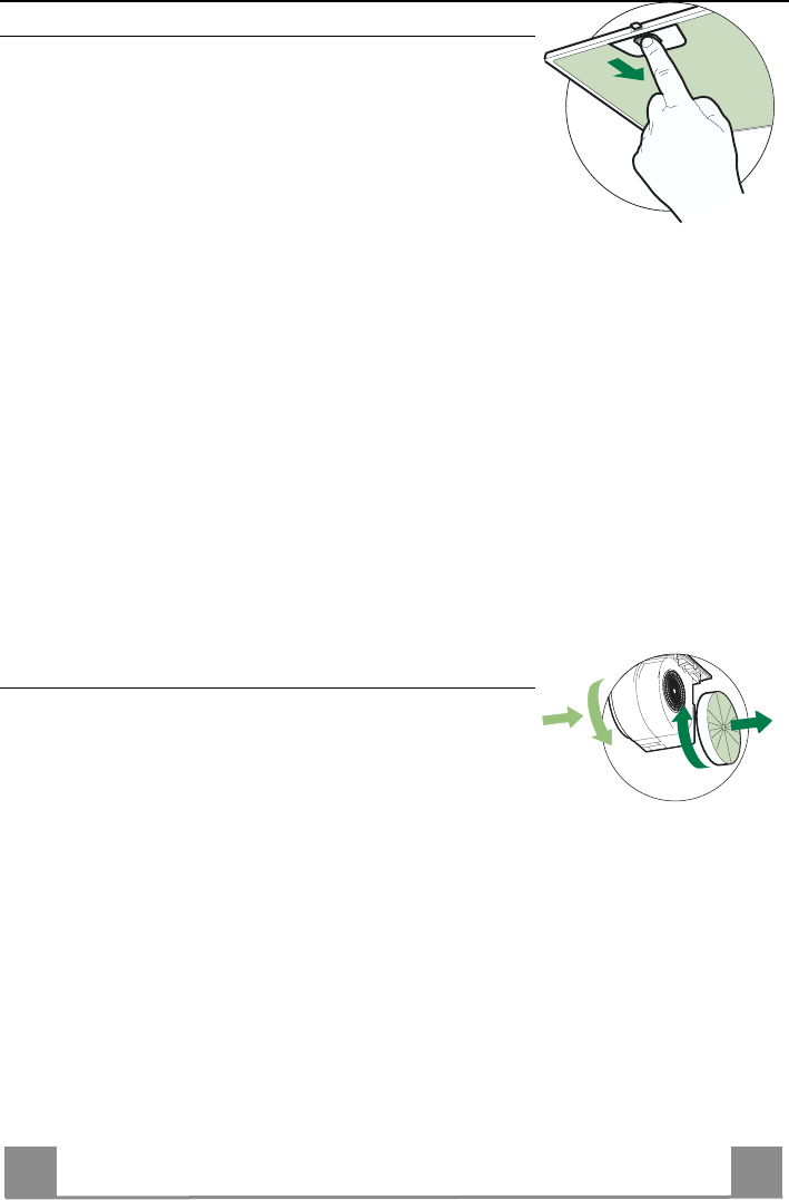
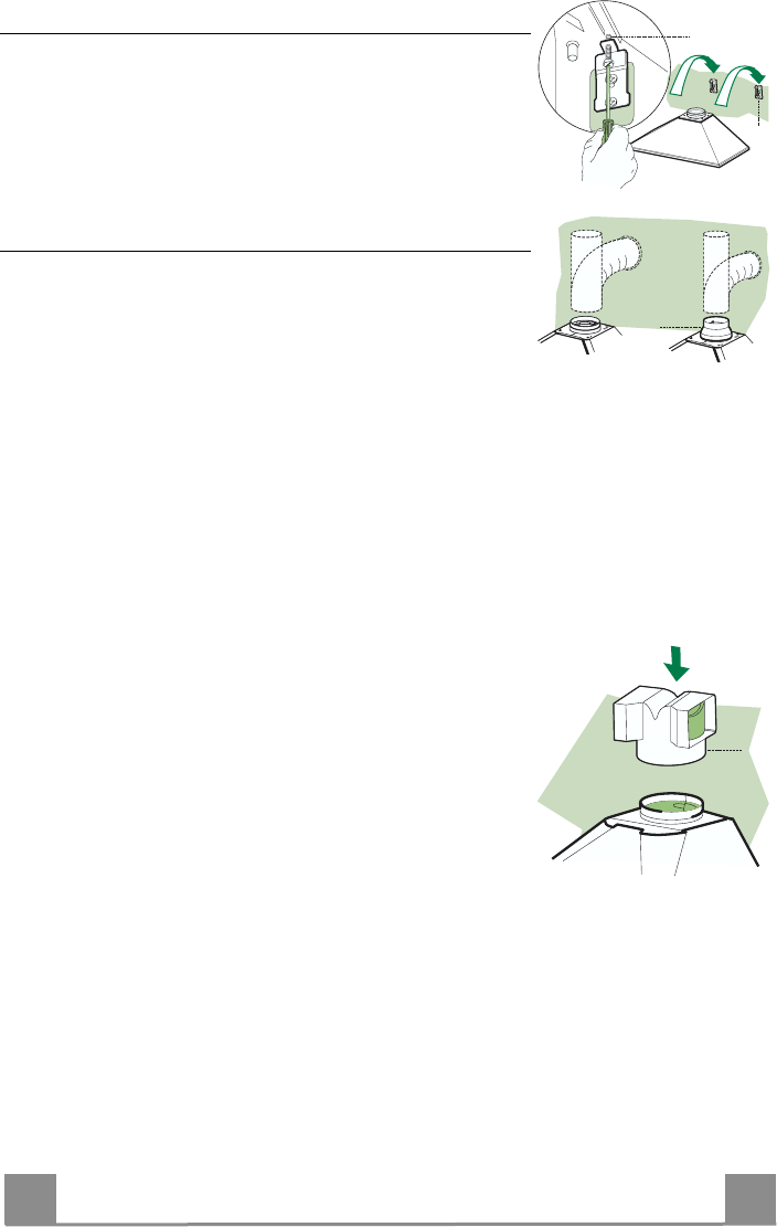
Mounting the hood body
• Screw the two screws 12d supplied onto the brackets 7.1.
• Hook the hood body onto the bracket 7.1, centring it around
the vertical line.
• Use the adjusting screws 12d underneath the hood to level the
hood body.
7.1
12.d
Connections
DUCTED VERSION AIR EXHAUST SYSTEM
When installing the ducted version, connect the hood to the
chimney using either a flexible or rigid pipe ø 150 or 120 mm,
the choice of which is left to the installer.
• To install a ø 120 mm air exhaust connection, insert the re-
ducer flange 9 on the hood body outlet.
• Fix the pipe in position using sufficient pipe clamps (not sup-
plied).
• Remove any activated charcoal filters.
ø 120ø 150
9
RECIRCULATION VERSION AIR OUTLET
• Push fit the air outlet fitting 15 onto the air outlet of the hood
body.
• Ensure that the activated charcoal filters have been inserted.
15
EN
2
2
22
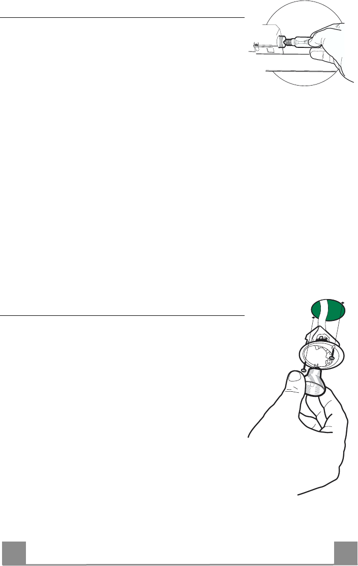
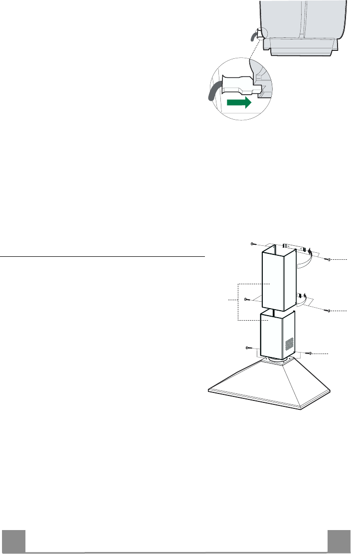
ELECTRICAL CONNECTION
• Connect the hood to the mains through a two-pole
switch having a contact gap of at least 3 mm.
• Remove the grease filters (see paragraph Mainte-
nance) being sure that the connector of the feeding
cable is correctly inserted in the socket placed on the
side of the fan.
Flue assembly
Upper exhaust flue
• Slightly widen the two sides of the upper flue and
hook them behind the brackets 7.2.1, making sure
that they are well seated.
• Secure the sides to the brackets using the 4 screws
12c (2,9 x 9,5) supplied.
Lower exhaust flue
• Slightly widen the two sides of the flue and hook
them between the upper flue and the wall, making
sure that they are well seated.
• Fix the lower part laterally to the hood body using
the 2 screws 12c (2,9 x 9,5) supplied.
• Make sure that the air outlet connection is aligned
with the chimney outlets.
12c
12c
12c
2.2
2.1
2
EN
2
3
23
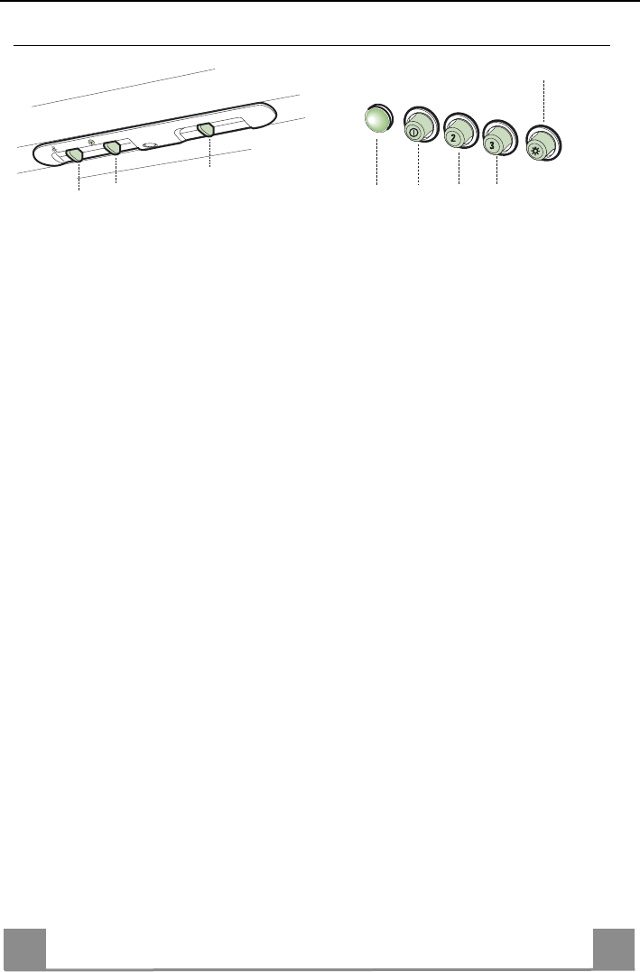
USE
Control panel
1
1
0
1
0
2
3
L
M
V
L
V1V2V3
S
LLight Switches the lighting system
on and off.
MMotor Switches the extractor motor
on and off.
VSpeed Sets the operating speed of
the extractor:
1. Low speed, used for a
continuous and silent air
change in the presence of
light cooking vapour.
2. Medium speed, suitable
for most operating condi-
tions given the optimum
treated air flow/noise
level ratio.
3. Maximum speed, used for
eliminating the highest
cooking vapour emission,
including long periods.
LLight Switches the lighting system
on and off.
SLed Motor running led.
V1Motor Switches the extractor motor
on and off at low speed.
Used to provide a continuous
and silent air change in the
presence of light cooking
vapours.
V2Speed Medium speed, suitable for
most operating conditions
given the optimum treated
air flow/noise level ratio.
V3Speed Maximum speed, used for
eliminating the highest cook-
ing vapour emission, includ-
ing long periods.
EN
2
4
24
MAINTENANCE
Grease filters
CLEANING METAL SELF- SUPPORTING GREASE FILTERS
• The filters must be cleaned every 2 months of operation, or
more frequently for particularly heavy usage, and can be
washed in a dishwasher.
• Remove the filters one at a time by pushing them towards
the back of the group and pulling down at the same time.
• Wash the filters, taking care not to bend them. Allow them
to dry before refitting.
• When refitting the filters, make sure that the handle is visible
on the outside.
Activated charcoal filter (Recirculation version)
These filters are not washable and cannot be regenerated, and
must be replaced approximately every 4 months of operation, or
more frequently with heavy usage.
REPLACING THE ACTIVATED CHARCOAL FILTER
• Remove the metal grease filters
• Remove the saturated activated charcoal filter as shown (A).
• Fit the new filters (B).
• Replace the metal grease filters.
A
B
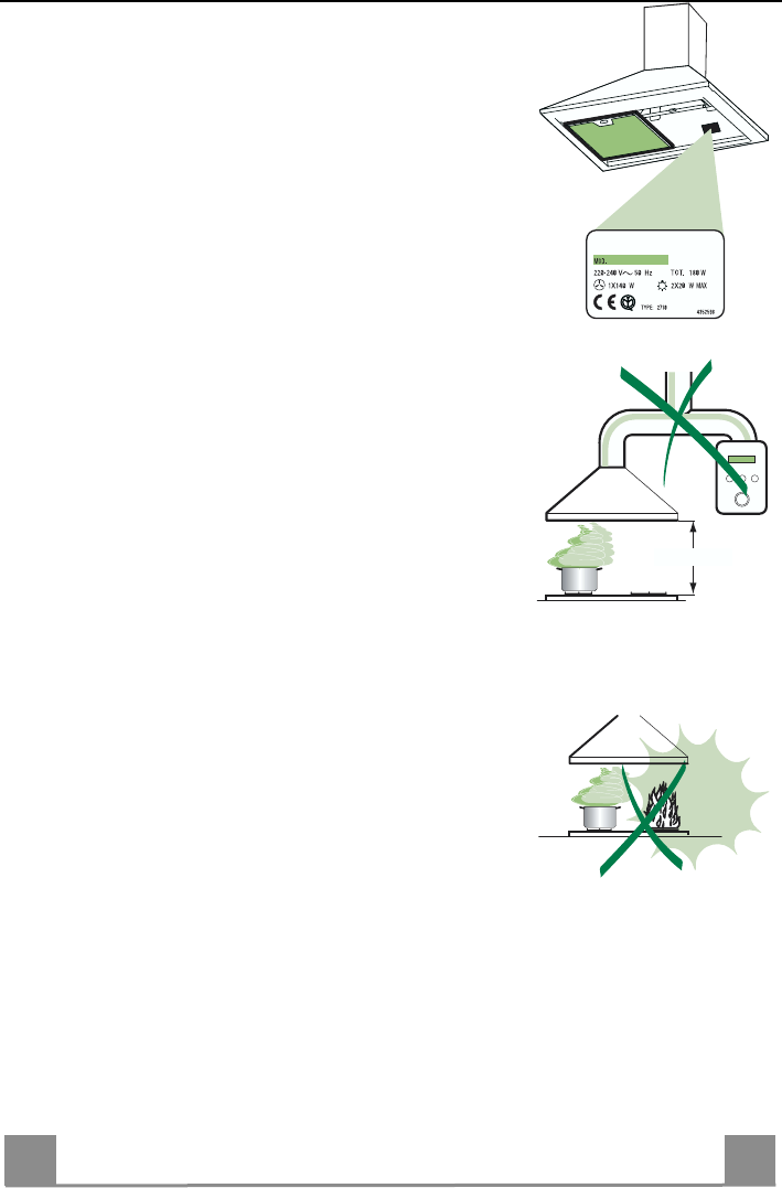
4329653_ver8
Dir.89/336/CEE
73/23/CEE
93/68/CEE
Il simbolo sul prodotto o sulla confezione indica che il prodotto non deve essere considerato come un normale rifiuto domestico, ma deve essere
portato nel punto di raccolta appropriato per il riciclaggio di apparecchiature elettriche ed elettroniche. Provvedendo a smaltire questo prodotto in modo
appropriato, si contribuisce a evitare potenziali conseguenze negative per l’ambiente e per la salute, che potrebbero derivare da uno smaltimento inade-
guato del prodotto. Per informazioni più dettagliate sul riciclaggio di questo prodotto, contattare l’ufficio comunale, il servizio locale di smaltimento rifiuti o
il negozio in cui è stato acquistato il prodotto.
The symbol
on the product or on its packaging indicates that this product may not be treated as household waste. Instead it shall be handed over
to the applicable collection point for the recycling of electrical and electronic equipment. By ensuring this product is disposed of correctly, you will help
prevent potential negative consequences for the environment and human health, which could otherwise be caused by inappropriate waste handling of
this product. For more detailed information about recycling of this product, please contact your local city office, your household waste disposal service or
the shop where you purchased the product.
Le symbole
sur le produit ou son emballage indique que ce produit ne peut être traité comme déchet ménager. Il doit plutôt être remis au point de
ramassage concerné, se chargeant du recyclage du matériel électrique et électronique. En vous assurant que ce produit est éliminé correctement, vous
favorisez la prévention des conséquences négatives pour l’environnement et la santé humaine qui, sinon, seraient le résultat d’un traitement inapproprié
des déchets de ce produit. Pour obtenir plus de détails sur le recyclage de ce produit, veuillez prendre contact avec le bureau municipal de votre région,
votre service d’élimination des déchets ménagers ou le magasin où vous avez acheté le produit.
Das Symbol
auf dem Produkt oder seiner Verpackung weist darauf hin, dass dieses Produkt nicht als normaler Haushaltsabfall zu behandeln ist,
sondern an einem Sammelpunkt für das Recycling von elektrischen und elektronischen Geräten abgegeben werden muss. Durch Ihren Beitrag zum
korrekten Entsorgen dieses Produkts schützen Sie die Umwelt und die Gesundheit Ihrer Mitmenschen. Umwelt und Gesundheit werden durch falsches
Entsorgen gefährdet. Weitere Informationen über das Recycling dieses Produkts erhalten Sie von Ihrem Rathaus, Ihrer Müllabfuhr oder dem Geschäft, in
dem Sie das Produkt gekauft haben.
Het symbool
op het product of op de verpakking wijst erop dat dit product niet als huishoudafval mag worden behandeld. Het moet echter naar
een plaats worden gebracht waar elektrische en elektronische apparatuur wordt gerecycled. Als u ervoor zorgt dat dit product op de correcte manier
wordt verwijderd, voorkomt u mogelijk voor mens en milieu negatieve gevolgen die zich zouden kunnen voordoen in geval van verkeerde afvalbehande-
ling. Voor meer details in verband met het recyclen van dit product, neemt u het best contact op met de gemeentelijke instanties, het bedrijf of de dienst
belast met de verwijdering van huishoudafval of de winkel waar u het product hebt gekocht.
El símbolo
en el producto o en su embalaje indica que este producto no se puede tratar como desperdicios normales del hogar. Este producto
se debe entregar al punto de recolección de equipos eléctricos y electrónicos para reciclaje. Al asegurarse de que este producto se deseche correcta-
mente, usted ayudará a evitar posibles consecuencias negativas para el ambiente y la salud pública, lo cual podría ocurrir si este producto no se mani-
pula de forma adecuada. Para obtener información más detallada sobre el reciclaje de este producto, póngase en contacto con la administración de su
ciudad, con su servicio de desechos del hogar o con la tienda donde compró el producto.
O símbolo
no produto ou na embalagem indica que este produto não pode ser tratado como lixo doméstico. Em vez disso, deve ser entregue ao
centro de recolha selectiva para a reciclagem de equipamento eléctrico e electrónico. Ao garantir uma eliminação adequada deste produto, irá ajudar a
evitar eventuais consequências negativas para o meio ambiente e para a saúde pública, que, de outra forma, poderiam ser provocadas por um trata-
mento incorrecto do produto. Para obter informações mais pormenorizadas sobre a reciclagem deste produto, contacte os serviços municipalizados
locais, o centro de recolha selectiva da sua área de residência ou o estabelecimento onde adquiriu o produto.
Libble takes abuse of its services very seriously. We're committed to dealing with such abuse according to the laws in your country of residence. When you submit a report, we'll investigate it and take the appropriate action. We'll get back to you only if we require additional details or have more information to share.
Product:
Forumrules
To achieve meaningful questions, we apply the following rules:
First, read the manual;
Check if your question has been asked previously;
Try to ask your question as clearly as possible;
Did you already try to solve the problem? Please mention this;
Is your problem solved by a visitor then let him/her know in this forum;
To give a response to a question or answer, do not use this form but click on the button 'reply to this question';
Your question will be posted here and emailed to our subscribers. Therefore, avoid filling in personal details.
Register
Register getting emails for Zanussi ZHC 600 W at:
new questions and answers
new manuals
You will receive an email to register for one or both of the options.
Get your user manual by e-mail
Enter your email address to receive the manual of Zanussi ZHC 600 W in the language / languages: English, German, Dutch, French, Italian, Portuguese, Spanish as an attachment in your email.
The manual is 2,14 mb in size.
You will receive the manual in your email within minutes. If you have not received an email, then probably have entered the wrong email address or your mailbox is too full. In addition, it may be that your ISP may have a maximum size for emails to receive.
The manual is sent by email. Check your email
If you have not received an email with the manual within fifteen minutes, it may be that you have a entered a wrong email address or that your ISP has set a maximum size to receive email that is smaller than the size of the manual.
The email address you have provided is not correct.
Please check the email address and correct it.
Your question is posted on this page
Would you like to receive an email when new answers and questions are posted? Please enter your email address.