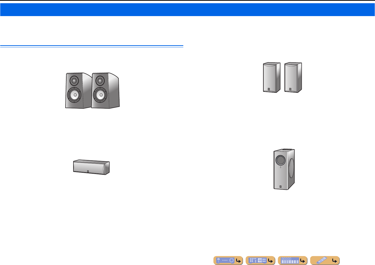
Check that you received all of the following parts.
•Remote control
•Batteries (AAA, R03, UM-4) x 2
•YPAO microphone
•AM loop antenna
•Indoor FM antenna
•VIDEO AUX input cover
•This manual is printed prior to production. Design and
specifications are subject to change in part as a result of
improvements, etc. In case of differences between the manual and
product, the product has priority.
•“
cHDMI1” (example) indicates the name of the parts on the
remote control. Refer to the “Part names and functions” (☞
p. 5)
for the information about each position of the parts.
•J
1 indicates that the reference is in the footnote. Refer to the
corresponding numbers on the bottom of the page.
•☞
indicates the page describing the related information.
•Click on the “” at the bottom of the page to display the
corresponding page in “Part names and functions.”
Front panel
Rear panel
Front panel display
Remote control
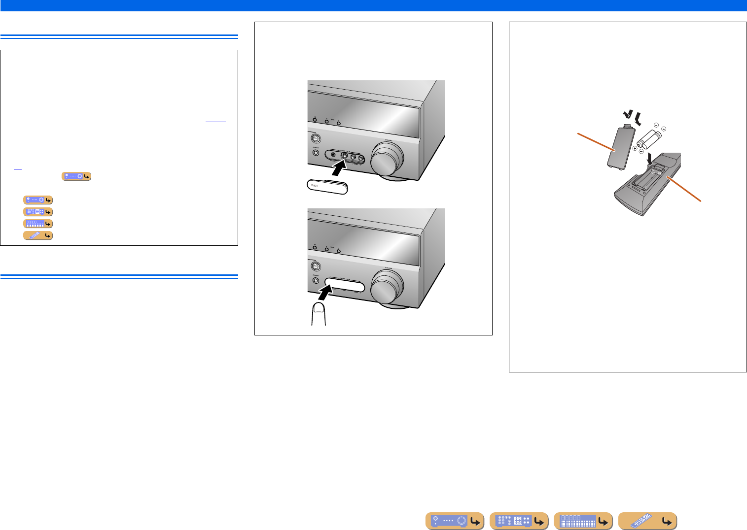
■Attaching the VIDEO AUX input cover (included)
To protect against dust, attach the supplied VIDEO AUX input
cover to the VIDEO AUX jacks when you do not use the jacks.
To remove the cover, push the left section of it.
Attach the cover
PUSH
Remove the cover
■Installing batteries in the remote control
When inserting batteries in the remote control, remove the
battery compartment cover from the reverse side of the remote
control, and insert two AAA batteries into the battery
compartment so that they match with the polarity markings (+
and -).
Replace the batteries with new ones if the following symptoms
become evident:
•The remote control can only be operated within a narrow range.
•
bTRANSMIT does not light up, or only lights dimly.
NOTE
If there are remote control codes for external components
registered to the remote control, removing the batteries for more
than two minutes, or leaving exhausted batteries in the remote
control, the remote control codes may be cleared. If this should
occur, replace the batteries with new ones, and set the remote
control codes.
a
c
b
Battery compartment
cover
Battery compartment
En 5
INTRODUCTION
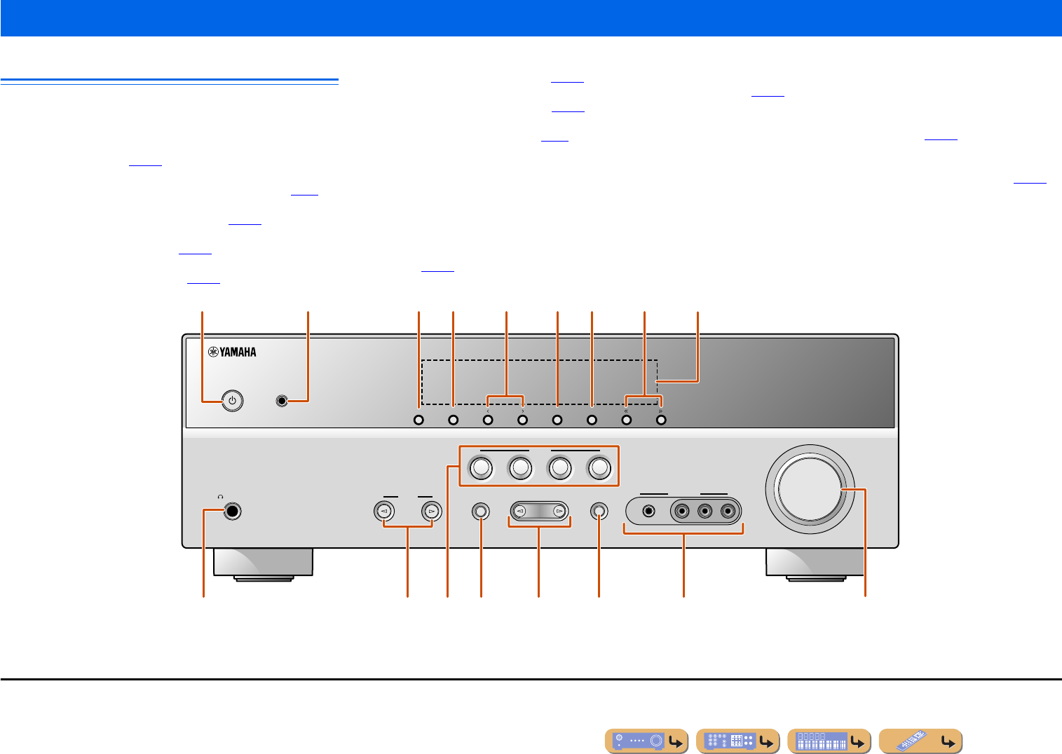
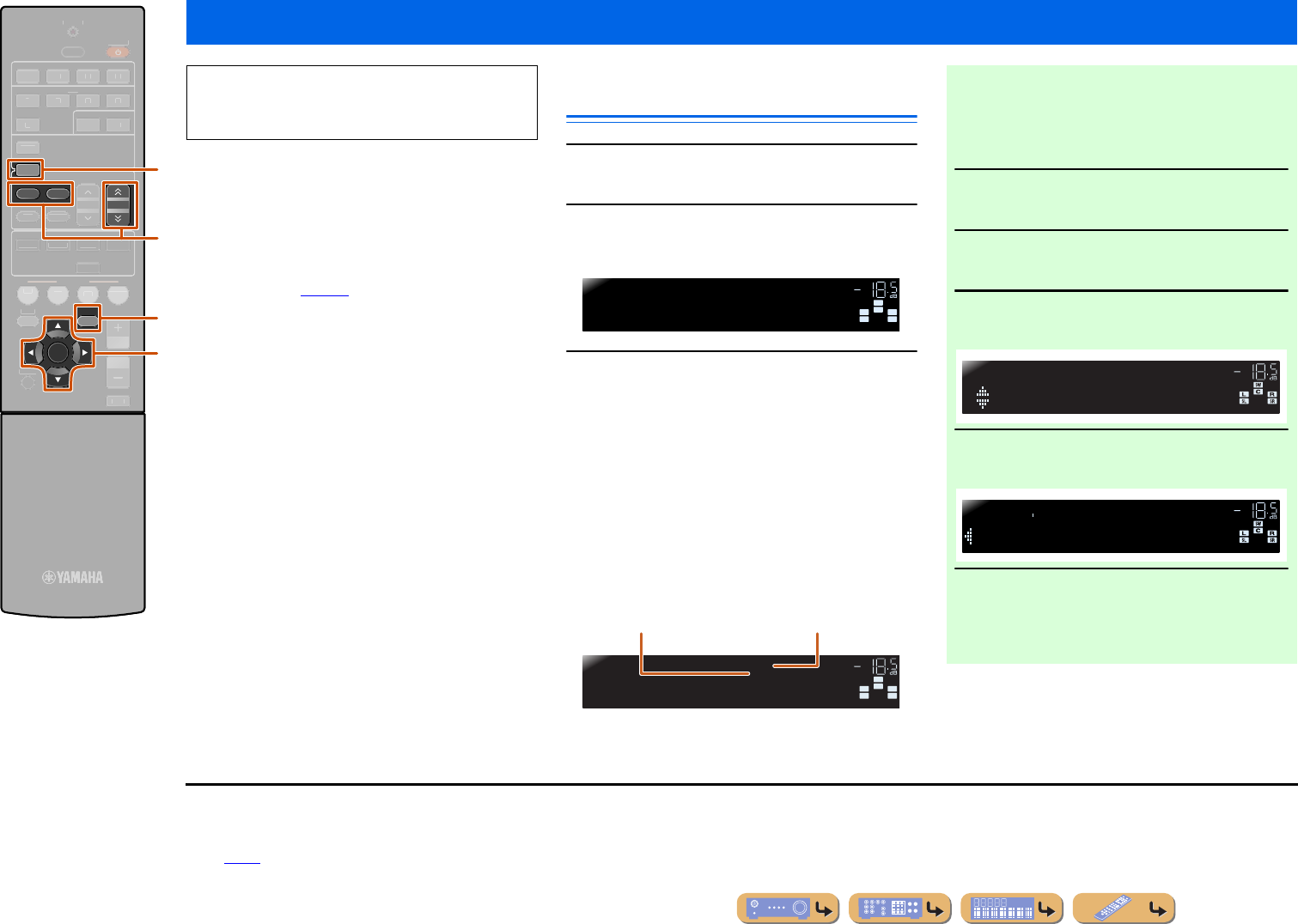
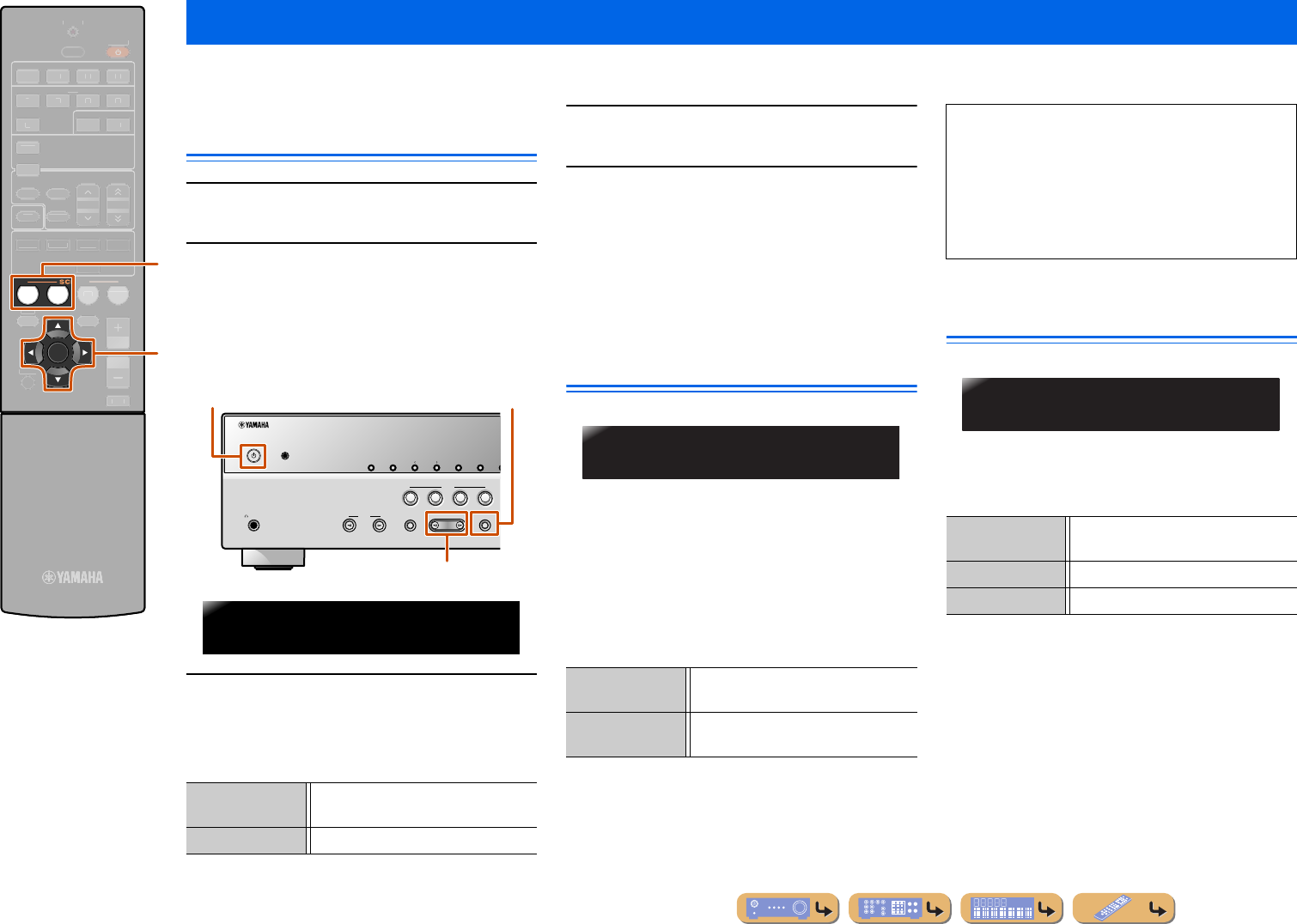
Front panel
aA (Power)
Switches this unit between on and standby modes.
bYPAO MIC jack
Connect the supplied YPAO microphone and adjust the speaker
balance automatically (☞
p. 21).
cINFO
Changes the information shown on the front panel display (☞
p. 7).
dMEMORY
Registers FM/AM stations as preset stations (☞
p. 31). J1
ePRESET j / i
Selects an FM/AM preset station (☞
p. 32). J1
fFM
Sets the FM/AM tuner band to FM (☞
p. 30). J1
gAM
Sets the FM/AM tuner band to AM (☞
p. 30). J1
hTUNING jj / ii
Changes FM/AM tuner frequencies (☞
p. 30). J1
iFront panel display
Displays information on this unit (☞
p. 7).
jPHONES jack
For plugging headphones in. Sound effects applied during playback
can also be heard through the headphones.
kINPUT l / h
Selects an input source from which to playback. Press either the left or
right key repeatedly to cycle through the input sources in order.
lSCENE
Switches the input source and the sound field program with a single
button (☞
p. 26). Press this key when this unit is in standby mode to
switch on the unit.
mTONE CONTROL
Adjusts high-frequency/low-frequency output of speakers/headphones
(☞
p. 25).
nPROGRAM l / h
Switches between the sound field effect (sound field program) you are
using and the surround sound decoder (☞
p. 26). Press either the left
or right key repeatedly to cycle through the input sources in order.
oSTRAIGHT
Changes a sound field program to straight decoding mode (☞
p. 27).
pVIDEO AUX jacks
For connecting video cameras, game consoles, and portable music
players to this unit temporarily.
Attach the supplied VIDEO AUX input cover when not using this
jack.
qVOLUME
Adjusts the volume level.
Part names and functions
VIDEO
AUX
PHONES
SILENT
CINEMA
TONE
CONTROL
STRAIGHT
VOLUME
TV
BD
DVD
CD
RADIO
INPUT
PROGRAM
SCENE
VIDEO
AUDI O
PORTABLE
LR
INFO
MEMORY
PRESET
FMAM
TUNING
YPAO MIC
mokn
a
ljq
b
p
i
cfegdh
J
1 :Usable when you have selected tuner input.
En 6
INTRODUCTION
Part names and functions
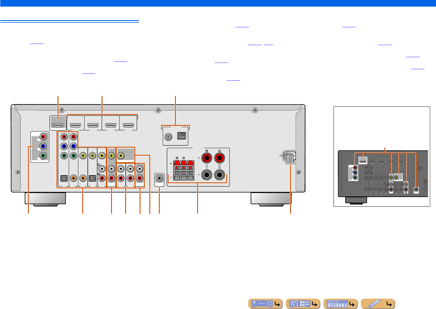
Rear panel
aHDMI OUT jack
For connecting an HDMI - compatible TV to output audio/video
signals to (☞
p. 13).
bHDMI1-4 jacks
For connecting external components equipped with HDMI-
compatible outputs to receive audio/video signals from (☞
p. 15).
cANTENNA jacks
For connecting AM and FM antennas (☞
p. 20).
dCOMPONENT VIDEO jacks
For connecting TV that are compatible with component video signals,
using three cables to output video signal (☞
p. 13).
eAV1-5 jacks
For connecting to external devices equipped with audio/video outputs
so that this unit can receive audio/video signals (☞
p. 16, p.17).
fAV OUT jacks
For outputting audio/video signals received when analog inputs (AV3-
5 or AUDIO1-2) are selected (☞
p. 19).
gAUDIO1-2 jacks
For connecting to external components equipped with analog audio
outputs to input sound into this unit (☞
p. 18).
hMONITOR OUT jack
For connecting a TV capable of receiving video input, and outputting
video signals to it (☞
p. 14).
iAUDIO OUT jacks
For outputting audio signals received when analog inputs such as the
AV5 or AUDIO1-2 jacks are selected (☞
p. 19).
jSUBWOOFER jack
For connecting a subwoofer with a built-in amplifier (☞
p. 11).
kSPEAKER terminals
For connecting the front, center, and surround speakers (☞
p. 11).
lPower cord
For connecting this unit to an AC wall outlet.
ANTENNA
FM
GND
AM
COMPONENT
VIDEO
P
R
P
B
Y
OPTICAL
(
TV
)
AV
1
AV
2
AV
3
AV
4
AV
5
AUD
IO 1
AUD
IO 2
COAXIAL
(
CD
)
COAXIAL
OPTICAL
VIDEO
CENTER
SURROUND
HDMI 1
(
BD/DVD
)
HDMI 2HDMI 3
HDMI 4
FRONT
COMPONENT
VIDEO
MONITOR OUT
P
R
P
B
Y
HDMI
OUT
MONITOR OUT
AV
OUT
SUBWOOFER
AUDIO
OUT
SPEAKERS
COMPONENT
VIDEO
MONITOR OUT
P
R
P
B
Y
HDMI
OUT
MONITOR OUT
AV
OUT
SUBWOOFER
ANTENNA
FM
G
ND
CO
MP
O
NENT
VIDE
O
P
R
P
B
Y
O
PTI
C
A
L
(
TV
)
AV 1
AV 2
AV 3
AV 4
AV 5
AU
D
IO 1
AU
D
IO 2
CO
AXIA
L
(
CD
)
COAXIA
L
O
PTI
C
AL
VIDE
O
S
URR
OU
HDMI 1
(
BD/DVD
)
HDMI 2
HDMI
3
HDMI
4
b
efjgik
c
dh
a
l
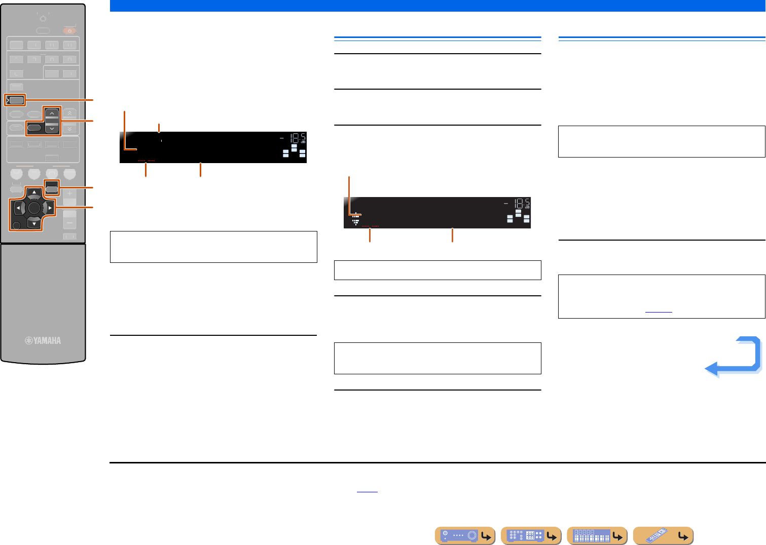
Distinguishing the input and output jacks
The area around the audio/video output jacks is
marked in white to prevent connection errors.
Use these jacks to output audio/video signals
to a TV or other external component.
Output jacks
En 7
INTRODUCTION
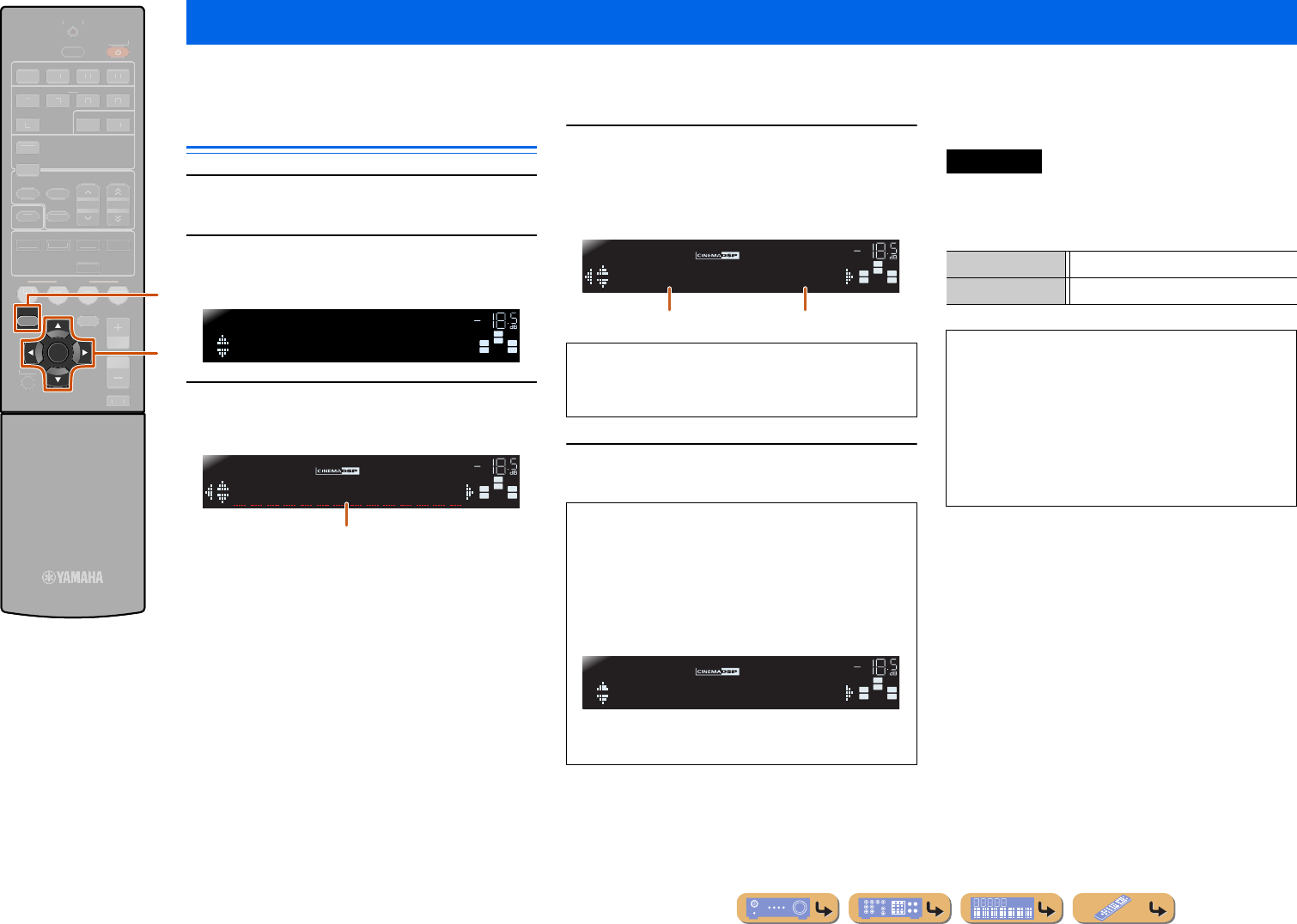
Part names and functions
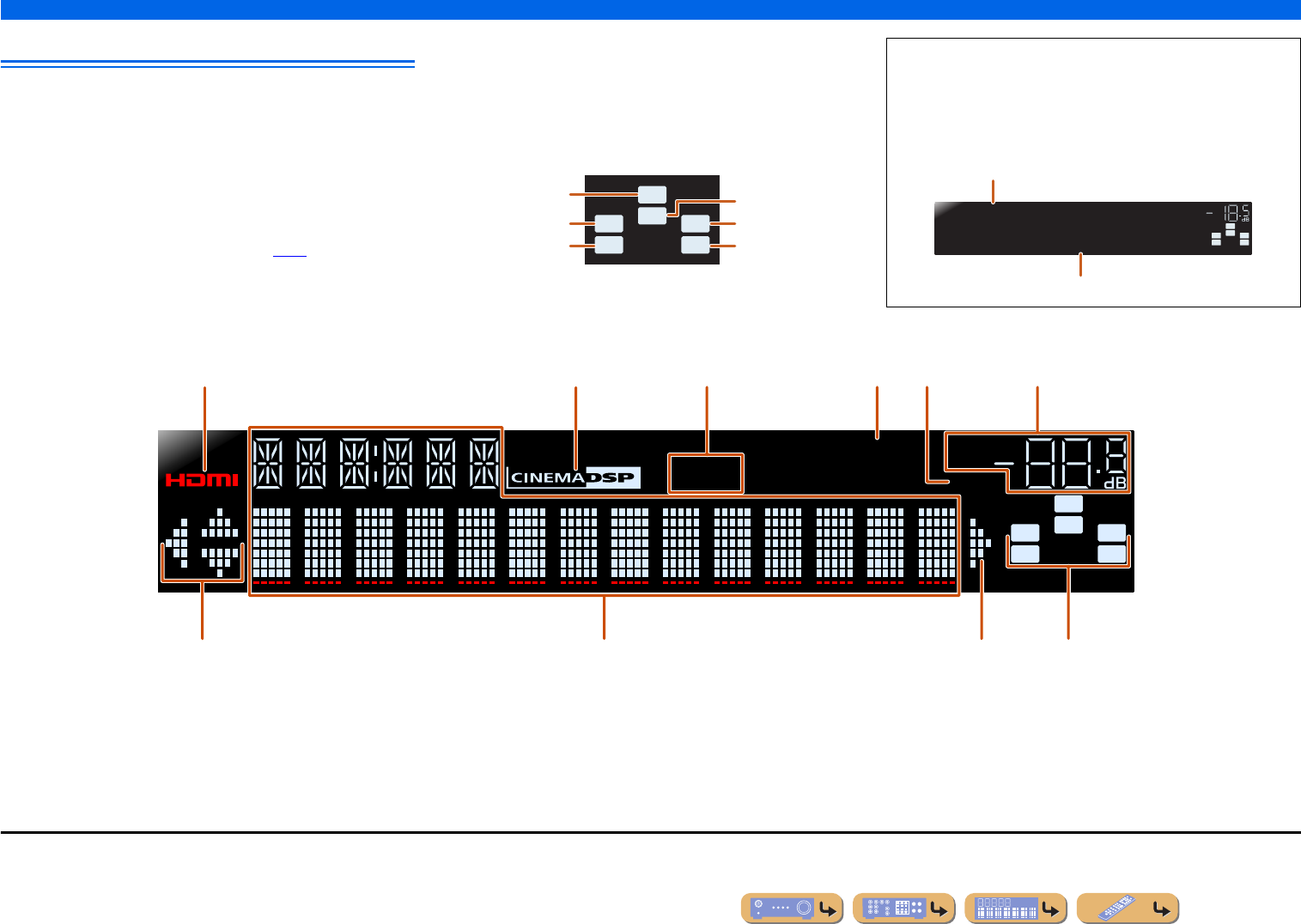
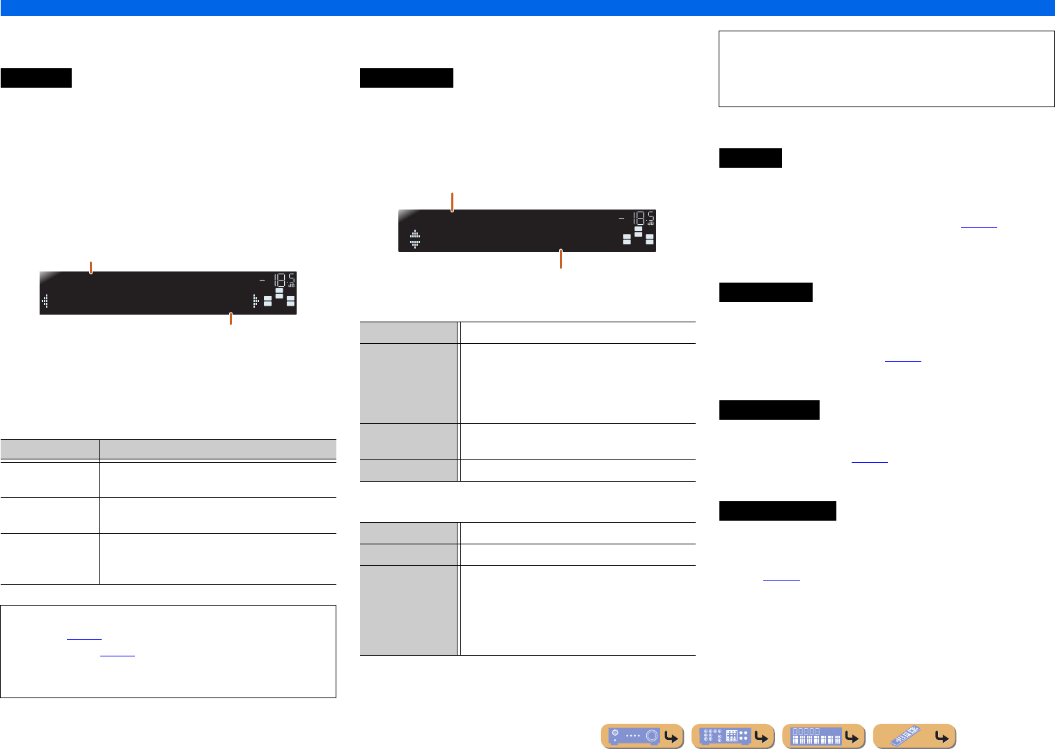
Front panel display
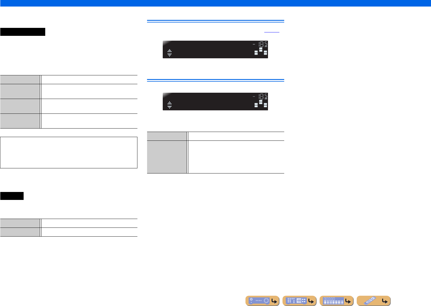
aHDMI indicator
Lights up during normal HDMI communication when any of the
HDMI 1-4 inputs are selected.
bCINEMA DSP indicator
Lights up when a sound field effect that uses CINEMA DSP
technology is selected.
cTuner indicator
Lights up when receiving an FM/AM broadcast.
dSLEEP indicator
Lights up when the sleep timer is activated (☞
p. 8).
eMUTE indicator
Flashes when audio is muted.
fVOLUME indicator
Displays the current volume level.
gCursor indicators
Light up if corresponding cursors on the remote control are available
for operations.
hMulti information display
Displays a range of information on menu items and settings.
iSpeaker indicators
Indicate speaker terminals from which signals are output.
SW
C
LR
SLSR
Front speaker L
Surround speaker L
Subwoofer
Front speaker R
Surround speaker R
Center speaker
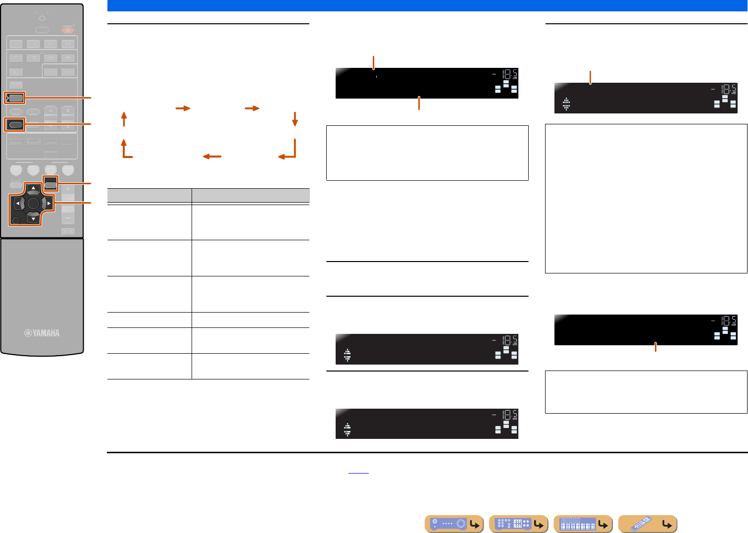
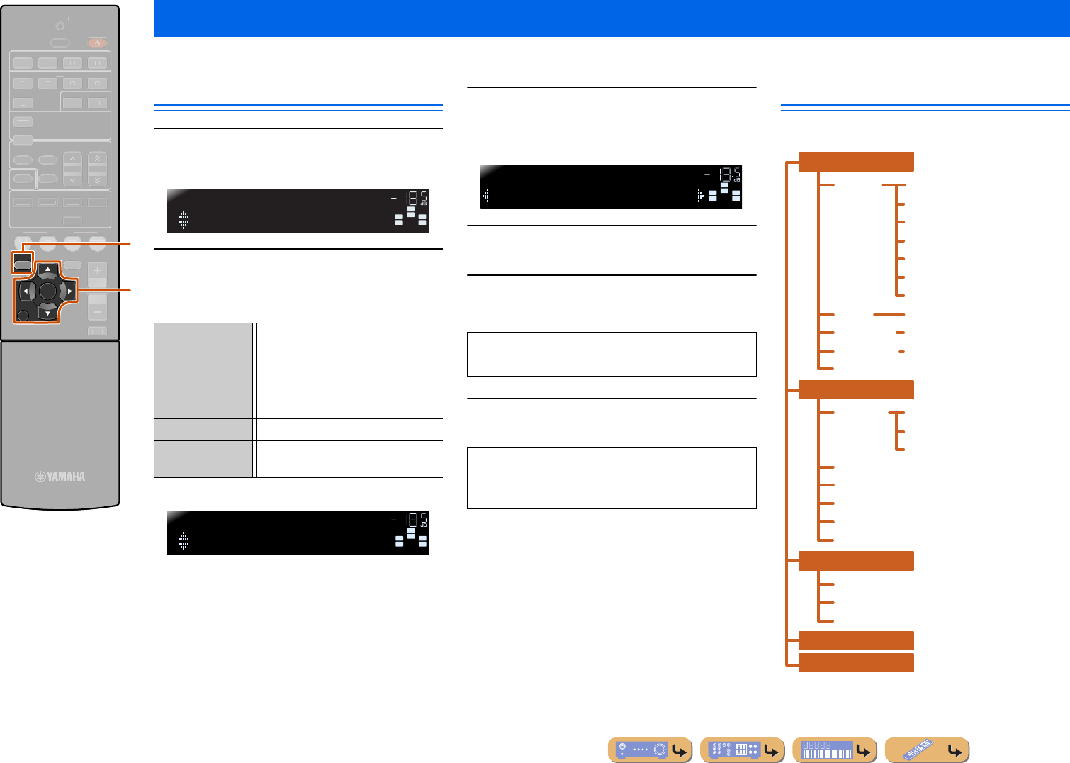
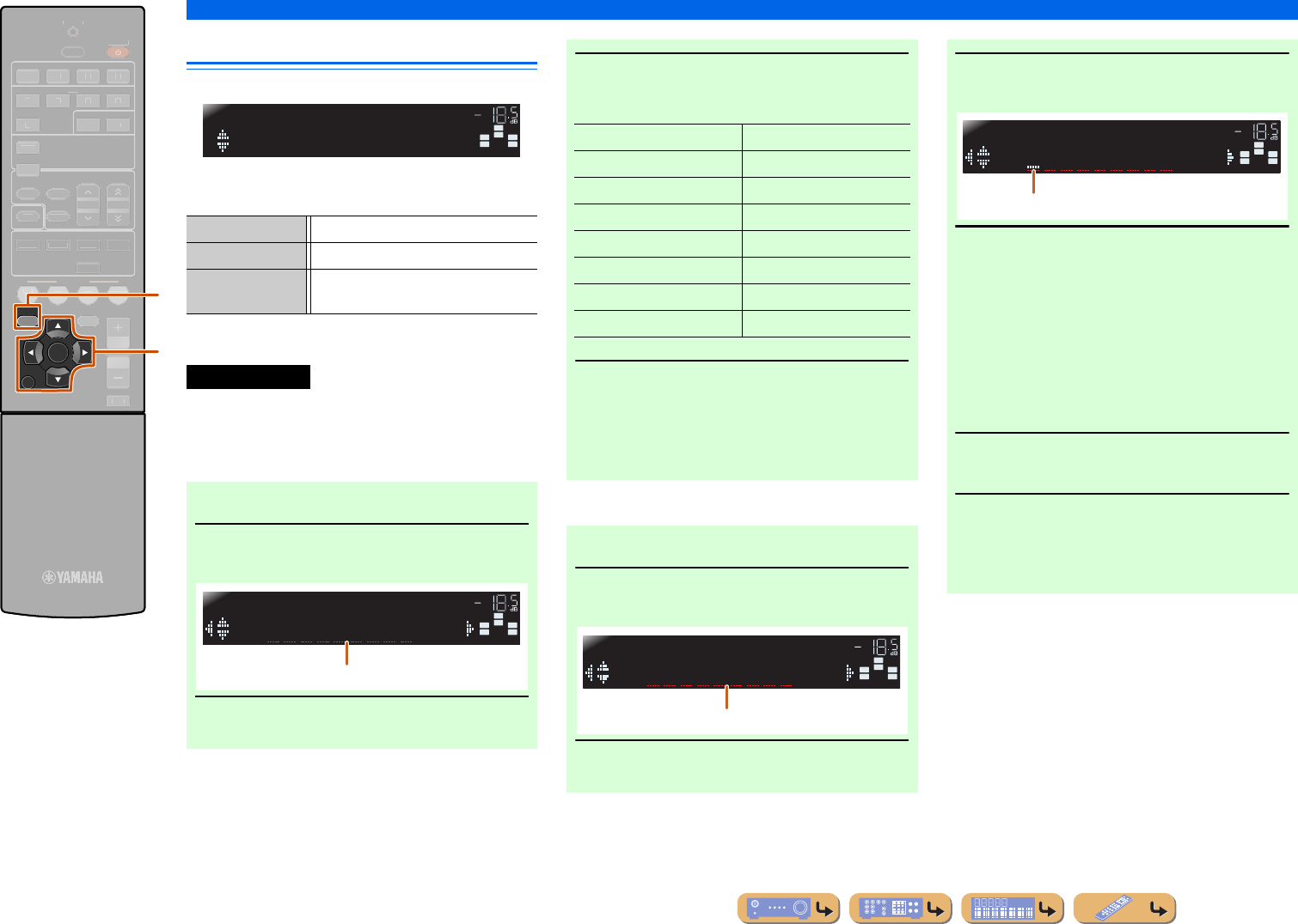
■Changing the front panel display
The front panel can display sound field programs and surround
decoder names as well as the active input source.
Press eINFO repeatedly to cycle through input source →
sound field program → surround decoder in order. J1
SW
C
L
SLSR
R
Straight
HDMI1
VOL.
Input source name
Sound field program (DSP program)
STEREO
SLEEP
VOL.
TUNED
SW
C
LR
SLSR
MUTE
abcdfe
ghig
J
1 :While selecting a tuner input, the FM/AM frequency is displayed instead of the input source.
En 8
INTRODUCTION
Part names and functions
Remote control
aRemote control signal transmitter
Transmits infrared signals.
bTRANSMIT
Lights up when a signal is output from the remote control.
cInput selector
Select an input source on this unit from which to playback.
dTuner keys
Operates the FM/AM tuner. These keys are used when using the tuner
input.
eINFO
Cycles the information displayed on the front panel display (the name
of the currently selected input source, the sound field program, the
surround decoder, the FM/AM tuner frequency, etc.)(☞
p. 7).
fSound selection keys
Switch between the sound field effect (sound field program) you are
using and the surround decoder (☞
p. 26).
gSCENE
Switches the input source and the sound field program with a single
button (☞
p. 26). Press this key when this unit is in standby mode to
switch on the unit.
hSETUP
Displays a detailed Setup menu for this unit (☞
p. 36).
iCursor B / C / D / E, ENTER, RETURN
jRECEIVER A (RECEIVER Power)
Switches this unit between on and standby modes.
kSLEEP
Sets this unit to place itself in standby mode automatically after a
specified period of time has elapsed (sleep timer). Press this key
repeatedly to set the time for the sleep timer function. The front panel
display indicator lights up when the sleep timer is activated.
lOPTION
Displays the Option menu for each input source (☞
p. 34).
mVOLUME +/-
Adjusts the volume level (☞
p. 25).
nMUTE
Turns the mute function of the sound output on and off (☞
p. 25).
RECEIVER
SCENE
OPTION
SETUP
RETURN
VOLUME
ENHANCER
SUR. DECODE
STRAIGHT
HDMI
AV
AUDIO
TRANSMIT
SLEEP
1234
1234
125
V-AUX
TUNER
FM
INFO
MEMORY
AM
PRESET
TUNING
MOVIEMUSIC
STEREO
BD
DVD
TV
CD
RADIO
MUTE
ENTER
a
b
k
j
c
d
f
g
h
l
m
n
i
e
HDMI1-4HDMI1-4 jacks
AV1-5AV1-5 jacks
AUDIO1-2AUDIO1-2 jacks
V-AUXFront panel VIDEO AUX jacks
TUNERFM/AM tuner
FMSets the FM/AM tuner band to FM.
AMSets the FM/AM tuner band to AM.
MEMORYPresets radio stations.
PRESET F / GSelects a preset station.
TUNING H / IChanges tuning frequencies.
Cursor B / C / D / ESelect menu items and change settings when
settings menus, etc are displayed.
ENTERConfirms a selected item.
RETURNReturns to the previous screen when setting
menus are displayed, or ends the menu display.
Sleep 120min.Sleep 90min.
Sleep 60min.Sleep 30min.Sleep Off
En 9
CONNECTIONS
This unit uses acoustic field effects and sound decoders to bring you the impact of a real movie theater or concert hall. These effects will be brought to you with ideal speaker positioning and
connections in your listening environment.
Speaker channels and functions
■
Front left and right speakers
The front speakers are used for the front channel sounds (stereo sound) and effect sounds.
Front speaker layout:
Place these speakers at an equal distance from the ideal listening position in the front of the room.
When using a projector screen, the appropriate top positions of the speakers are about 1/4 of the screen
from the bottom.
■
Center speaker
The center speaker is for the center channel sounds (dialog, vocals, etc.).
Center speaker layout:
Place it halfway between the left and right speakers. When using a TV, place the speaker just above or
just under the center of the TV with the front surfaces of the TV and the speaker aligned.
When using a screen, place it just under the center of the screen.
■
Surround left and right speakers
The surround speakers are for effect and vocal sounds with the 5.1-channel speakers providing rear-
area sounds.
Surround speaker layout:
Place the speakers at the rear of the room on the left and right sides facing the listening position. They
should be placed between 60 degrees and 80 degrees from the listening position and with the speaker
tops at a height of 1.5 – 1.8 m from the floor.
■
Subwoofer
The subwoofer speaker is used for bass sounds and low-frequency effect (LFE) sounds included in
Dolby Digital and DTS. Use a subwoofer that is equipped with an internal amplifier.
Subwoofer speaker layout:
Place it exterior to the front left and right speakers facing slightly inward to reduce echoes from the
Connect your speakers to their respective terminals on the rear panel.
•Connect at least two speakers (front left and right).
•If you cannot connect all five speakers, give priority to the surround speakers.
•The surround speakers should be placed between 60 degrees and 80 degrees from the listening position.
■CRT monitors
We recommend that you use magnetically shielded speakers to avoid video distortion, especially for
the front and center speakers near the screen.
If your screen still gets interference from magnetically shielded speakers, move the speakers farther
away from your TV.
60q
60q
80q
80q
Front speaker R
Front speaker L
Center speaker
Surround speaker L
Surround
speaker R
Subwoofer
CAUTION
•Remove the AC power cord of this unit from the power outlet before connecting the speakers.
•Generally speaker cables consist of two parallel insulated cables. One of these cables is a different
color, or has a line running along it, to indicate different polarity. Insert the different colored (or lined)
cable into the “+” (positive, red) terminal on this unit and the speakers, and the other cable into the “-”
(minus, black) terminal.
•Be careful that the core of the speaker cable does not touch anything or come into contact with the metal
areas of this unit. This may damage this unit or the speakers. If the speaker cables short circuit,
“CHECK SP WIRES!” will appear on the front panel display when this unit is switched on.
ANTENNA
FM
GND
AM
AUDI O
2
CENTER
SURROUND
H
DMI 4
FRONT
O
R OUT
SUBWOOFER
AUDI O
OUT
SPEAKERS
R L
R L
Surround speaker
Front speaker
SubwooferCenter speaker
En 11
CONNECTIONS
Connecting speakers
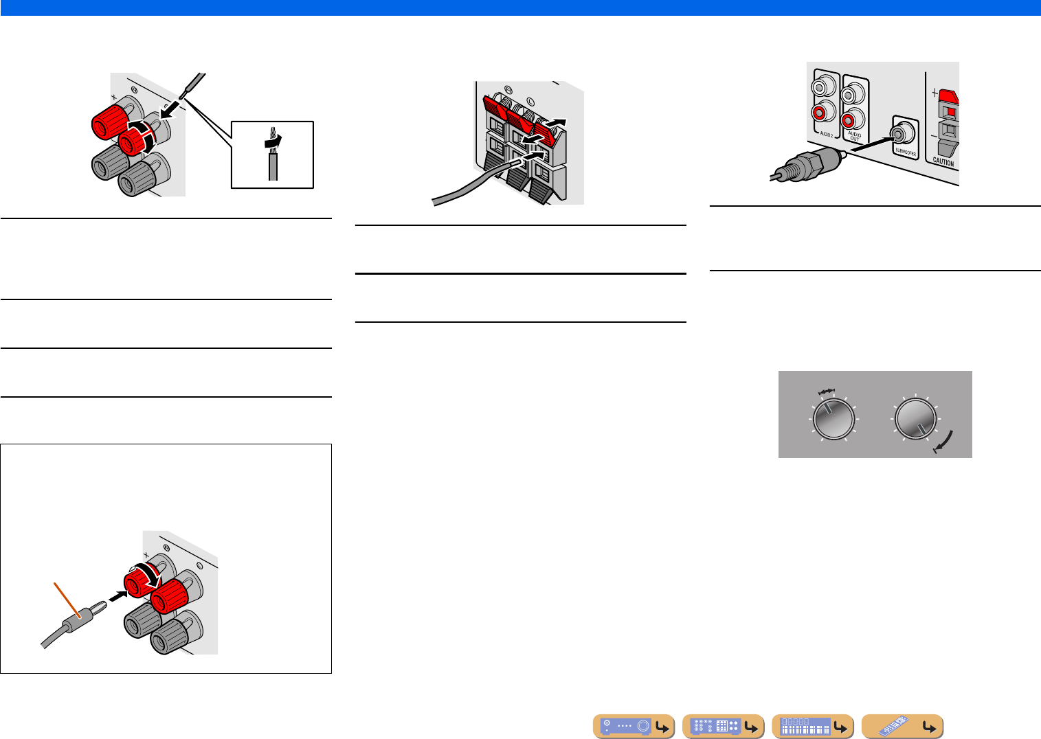
■
Connecting front speakers
1
Remove approximately 10mm of insulation from the
ends of the speaker cables, and twist the bare wires
of the cables together firmly so that they will not
cause short circuits.
2
Loosen the speaker terminals.
3
Insert the bare wire of the speaker cable into the gap
on the side of the terminal.
4
Tighten the terminal.
■
Connecting center speakers / surround
speakers
1
Press the tab on the speaker terminal down.
2
Insert the speaker cable end into the terminal.
3
Lift the tab to fix the speaker cable in place.
■
Connecting the subwoofer
1
Connect the subwoofer input jack to the
SUBWOOFER jack on this unit with an audio pin
cable.
2
Set the subwoofer volume as follows.
Volume: Set to approximately half volume (or slightly less than
half).
Crossover frequency (if available): Set to maximum.
Connecting the banana plug (Except U.K., Europe,
Asia and Korea models)
Tighten the knob, and then insert the banana plug into the end of
the terminal.
FRONT
KERS
2
2
3
1
4
4
FRONT
KERS
Banana plug
CENTER
SURROUND
SPEAKE
2
2
3
3
1
1
VOLUME
MINMAX
CROSSOVER/
HIGH CUT
MINMAX
Subwoofer examples
En 12
CONNECTIONS
Cable plugs and jacks
The main unit is equipped with the following input/output jacks. Use jacks and cables appropriate for
components that you are going to connect.
■
Audio/Video jacks
HDMI jacks
Digital video and digital sound are transmitted through a single jack.
Only use an HDMI cable.
■
Analog video jacks
■
Audio jacks
Connecting external devices
•Use a 19-pin HDMI cable with the HDMI logo.
•We recommend using a cable less than 5.0 m long to prevent signal quality degradation.
COMPONENT VIDEO jacks
The signal is separated into three components:
luminance (Y), chrominance blue (P
B), and
chrominance red (P
R).
Use component video pin cables with three plugs.
VIDEO jack
This jack transmits conventional analog video
signals.
Use video pin cables.
HDMI cable
Component video pin cable
Video pin cable
OPTICAL jacks
These jacks transmit optical digital audio signals.
Use fiber-optic cables for optical digital audio
signals.
COAXIAL jacks
These jacks transmit coaxial digital audio signals.
Use pin cables for digital audio signals.
AUDIO jacks
These jacks transmit conventional analog audio
signals.
Use stereo pin cables, connecting the red plug to
the red R jack, and the white plug to the white L
jack.
PORTABLE jack
This jack transmits conventional analog audio
signals.
Use a stereo mini-plug cable when connecting.
Digital audio fiber-optic cable
Digital audio pin cable
Stereo audio pin cable
Stereo mini-plug cable
En 13
CONNECTIONS
Connecting external devices
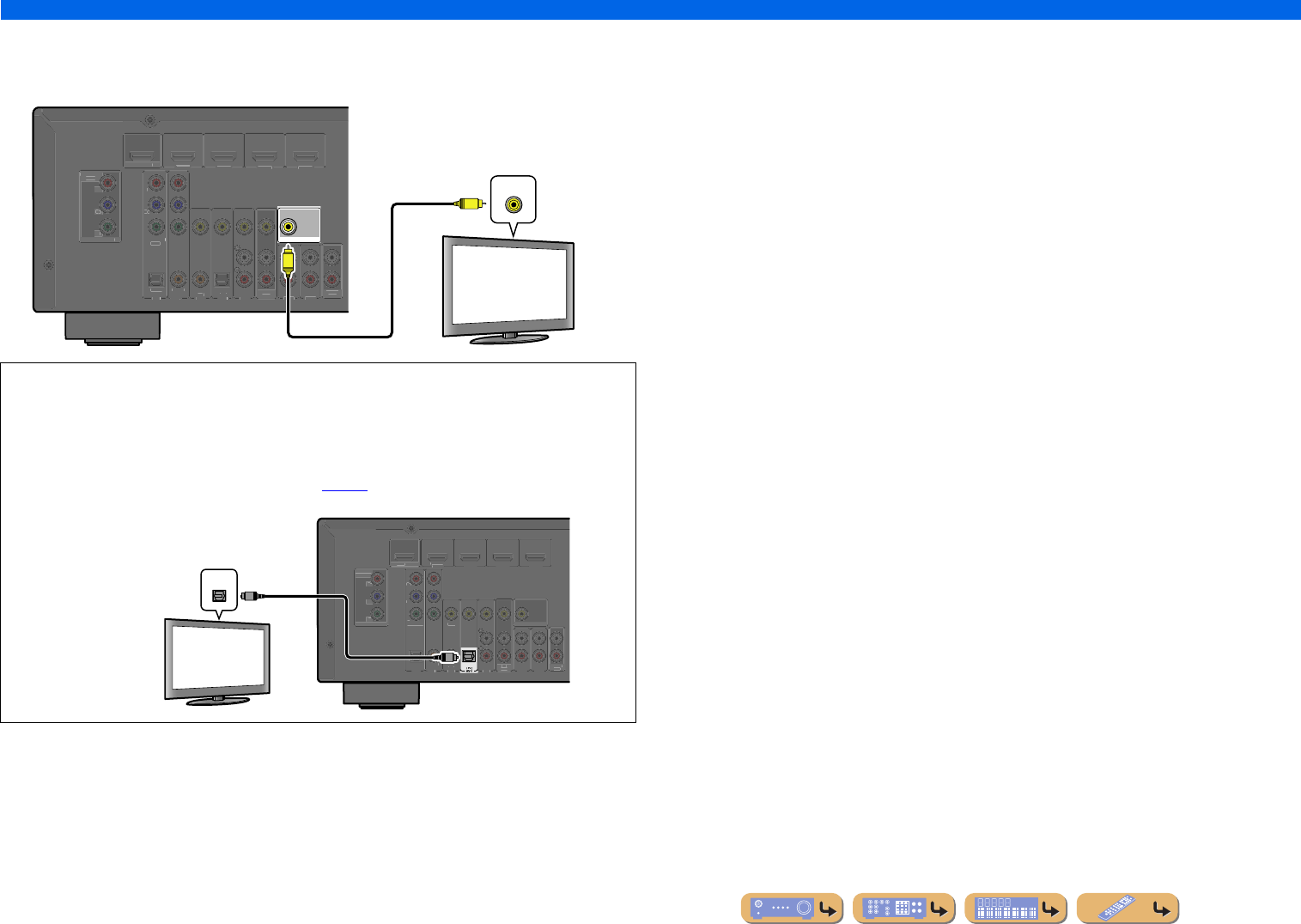
Connecting a TV monitor
This unit is equipped with the following three types of output jack for connection to a TV.
HDMI OUT, COMPONENT VIDEO or VIDEO. Select the proper connection according to the input
signal format supported by your TV.
This unit will receive HDMI, component, or video signals in the same format as transmitted by the
output devices.
For example, these three output devices must be connected to the monitor by matching input/output
jacks and cables, and then you must change the TV’s input mode to the proper setting.
■
Connecting an HDMI video monitor
Connect the HDMI cable to the HDMI OUT jack.
■
Connecting a component video monitor
Connect the component video cable to the COMPONENT VIDEO (MONITOR OUT) jacks.
COMPONENT
VIDEO
MONITOR OUT
P
R
P
B
Y
HDMI
OUT
MONITOR OUT
COMPONENT
V
IDEO
P
R
P
B
Y
V
IDE
O
HDMI
1
(
B
D/DV
D
)
HDMI 2
H
DMI 3
HDMI 4
HDMI OUT jack
COMPONENT VIDEO jacks
(MONITOR OUT)
VIDEO jack
(MONITOR OUT)
COMPONENT
VIDEO
HDMI
VIDEO
COMPONENT
VIDEO
HDMI
VIDEO
InputOutput
TV
HDMI input
Component
video input
Video input
•Use a 19-pin HDMI cable with the HDMI logo.
•We recommend using a cable less than 5.0 m long to prevent signal quality degradation.
HDMI
OUT
C
OMPONEN
T
V
IDE
O
P
R
P
B
Y
O
PTICA
L
(
TV
)
AV 1
AV 2
AV 3
AV 4
AV 5
AUDIO 1
AUDIO 2
CO
AXIA
L
(
C
D
)
CO
AXIAL
O
PTI
C
A
L
V
IDE
O
HDMI
1
(
B
D/DV
D
)
HDMI 2
HDMI
3
HDMI 4
CO
MP
O
NEN
T
V
IDE
O
MO
NIT
O
R
OUT
P
R
P
B
Y
M
O
NIT
O
R
OUT
AV
OU
T
AUDI
O
OUT
HDMI
HDMI
HDMI
HDMI input
TV
COMPONENT
VIDEO
MONITOR OUT
P
R
P
B
Y
COMPONENT
V
IDE
O
P
R
P
B
Y
O
PTICA
L
(
TV
)
AV 1
AV 2
AV 3
AV 4
AV 5
AUDIO 1
AUDIO 2
CO
AXIA
L
(
C
D
)
CO
AXIAL
O
PTI
C
AL
V
IDE
O
HDMI
1
(
BD/DV
D
)
HDMI 2
H
DMI
3
HDMI 4
HDM
I
OU
T
MO
NIT
O
R
OUT
AV
O
UT
A
UDI
O
OU
T
COMPONENT
VIDEO
Y
P
R
P
B
Y
P
R
P
B
Component video input
TV
En 14
CONNECTIONS
Connecting external devices
■
Connecting a video monitor
Connect the video pin cable to the VIDEO (MONITOR OUT) jack.
■Listening to TV audio
To transmit sound from the TV to this unit, connect its AV1-5 or AUDIO1-2 jacks to the TV’s
AUDIO OUT jacks.
If the TV supports optical digital audio output, we recommend that you connect the TV audio output
to the receiver’s AV4 jack. Connecting to AV4 allows you to switch the input source to AV4 with just
a single key operation using the SCENE function (☞
p. 26).
MONITOR OUT
COMPONENT
V
IDE
O
P
R
P
B
Y
O
PTICA
L
(
TV
)
AV 1
AV 2
AV 3
AV 4
AV 5
AUDIO 1
AUDIO 2
CO
AXIA
L
(
C
D
)
CO
AXIAL
O
PTI
C
AL
V
IDE
O
HDMI
1
(
BD/DV
D
)
HDMI 2
H
DMI
3
HDMI 4
CO
MP
O
NEN
T
V
IDEO
M
O
NIT
O
R
OUT
P
R
P
B
Y
HDM
I
OU
T
AV
O
UT
A
UDI
O
OU
T
VIDEO
V
V
Video input
TV
OPTICAL
CO
MP
O
NEN
T
VIDE
O
P
R
P
B
Y
O
PTICA
L
AV 1
AV 2
AV 3
AV 5
AU
D
IO
1
A
UDIO
2
CO
AXIAL
(
C
D
)
CO
AXIA
L
VIDE
O
HDMI 1
(
BD
/
DV
D
)
HDMI 2
HDMI
3
HDMI
4
COMPONEN
T
V
IDE
O
M
O
NIT
O
R
O
U
T
P
R
P
B
Y
HDMI
O
U
T
MO
NIT
O
R
O
U
T
AV
O
UT
A
U
DI
O
O
U
T
OPTICAL
O
O
Audio output
(Optical)
TV
En 15
CONNECTIONS
Connecting external devices
Connecting BD/DVD players and other devices
This unit has the following input jacks. Connect them to the appropriate output jacks on
the external components.
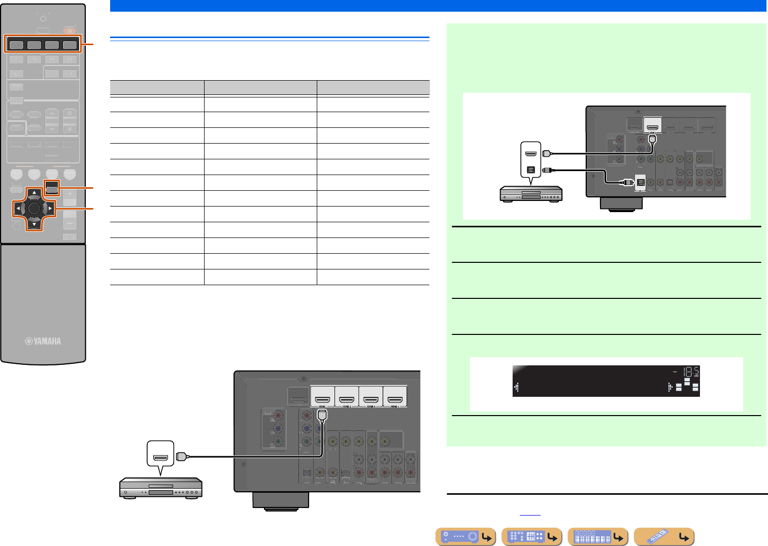
■
Connecting BD/DVD players and other devices with
HDMI
Connect the device with an HDMI cable to one of the HDMI1-4 jacks.
Select the HDMI input (HDMI1-4) that the external device is connected to for
playback.
OPTION
HDMI
1234
ENTER
R
ECEIVER
SC
ENE
S
ET
UP
RETURN
VO
L
U
M
E
ENHAN
C
E
R
SU
R. DE
CO
DE
S
TRAI
G
HT
AV
A
UDI
O
TRAN
S
MIT
S
LEE
P
1
2
3
4
1
2
5
V-A
U
X
TUNER
FM
I
NF
O
M
EM
O
RY
AM
P
RE
S
ET
T
U
NIN
G
MO
VIE
MUS
I
C
S
TERE
O
B
D
D
VD
TV
CD
RADI
O
MU
T
E
l
i
c
cInput selector
iCursor C / D / E
iENTER
lOPTION
Input jackVideo inputAudio input
HDMI1HDMIHDMI
HDMI2HDMIHDMI
HDMI3HDMIHDMI
HDMI4HDMIHDMI
AV1Component videoOptical
AV2Component videoCoaxial digital
AV3VideoCoaxial digital
AV4VideoOptical
AV5VideoAnalog (Stereo)
AUDIO1---Analog (Stereo)
AUDIO2---Analog (Stereo)
VIDEO AUXVideoAnalog (Stereo)
(
BD/DVD
)
COMPONENT
VIDE
O
P
R
P
B
Y
OPTICAL
(
TV
)
AV 1
AV 2
AV 3
AV 4
AV 5
AUDIO 1
AUDIO 2
CO
AXIAL
(
C
D
)
CO
AXIAL
O
PTI
C
AL
VIDE
O
CO
MP
O
NEN
T
VIDEO
M
O
NIT
O
R
OU
T
P
R
P
B
Y
H
DMI
OU
T
MO
NIT
O
R
OU
T
AV
O
UT
A
UDIO
OU
T
HDMI
HDMI
HDMI
HDMI output
BD/DVD player
■Receiving audio from other input sources
This unit can use the AV1-5 or AUDIO1-2 input jacks to receive audio signals from
other audio input sources.
For example, if an external device cannot produce audio signals from an HDMI jack,
use the following method to change the audio input.
1
Use the cInput selector to select the desired HDMI input source.
2
Press lOPTION to display the Option menu. J1
3
Press iCursorC until “Audio In” is displayed, and then press
iENTER.
4
Press iCursorD / E to select the audio input source.
5
Once you have completed the setup, press lOPTION to close the
Option menu.
J
1 :See the section on “Configuring the settings specific for each input source (Option menu)” for details on
the Option menu (☞
p. 34).
OPTICAL
(
BD/DVD
)
CO
MP
O
NEN
T
VIDEO
P
R
P
B
Y
(
TV
)
A
V
2
A
V
3
A
V
4
A
V
5
AUDIO 1
AUDI O 2
CO
AXIA
L
(
C
D
)
CO
AXIAL
O
PTI
C
A
L
VIDEO
HDMI 2HDMI
3
HDMI 4
CO
MP
O
NEN
T
V
IDE
O
MONITOR OUT
P
R
P
B
Y
HDMI
OUT
M
O
NIT
O
R
OUT
AV
OU
T
A
UDI
O
OU
T
HDMI
OPTICAL
HDMI
HDMI
O
O
HDMI/Audio (Optical)
output
BD/DVD player
SW
C
L
SLSR
R
Audio;;;;;;AV1
HDMI1
VOL.
If you have selected AV1 input audio (optical digital)
En 16
CONNECTIONS
Connecting external devices
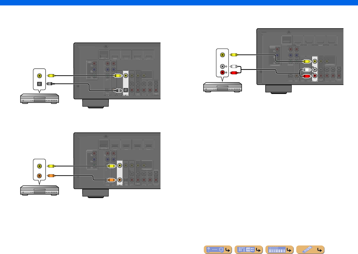
■
Connecting BD/DVD players and other devices with component
cables
Connect the device with a component video cable to one of the AV1-2 input jacks.
Using optical digital audio output sources
Select the AV1 input that the external device is connected to for playback.
Using coaxial digital audio output sources
Select the AV2 input that the external device is connected to for playback.
COMPONENT
VIDEO
P
R
P
B
Y
OPTICAL
AV 1
(
TV
)
AV 2
AV 3
AV 4
AV 5
AUDIO 1
AUDIO 2
CO
AXIAL
(
CD
)
CO
AXIA
L
O
PTI
C
A
L
VIDE
O
HDMI
1
(
B
D/DVD
)
HDMI 2
HDMI
3
HDMI 4
CO
MP
O
NENT
VIDE
O
MO
NIT
O
R
OU
T
P
R
P
B
Y
HDM
I
OUT
M
O
NIT
O
R
OU
T
AV
OU
T
AUDI O
OUT
COMPONENT
VIDEO
Y
P
R
P
B
Y
P
R
P
B
O
OPTICAL
O
Component video / Audio (Optical)
output
BD/DVD player
AV 2
COAXIAL
C
OMPONEN
T
VIDE
O
P
R
P
B
Y
OPTICAL
(
TV
)
AV 1
AV 3
AV 4
AV 5
AUDIO 1
AUDIO 2
(
CD
)
CO
AXIA
L
O
PTI
C
A
L
VIDE
O
HDMI
1
(
B
D/DVD
)
HDMI 2
HDMI
3
HDMI 4
CO
MP
O
NENT
VIDE
O
MO
NIT
O
R
OU
T
P
R
P
B
Y
HDM
I
OUT
M
O
NIT
O
R
OU
T
AV
OU
T
AUDI O
OUT
COMPONENT
VIDEO
COAXIAL
Y
P
R
C
P
B
Y
P
R
P
B
C
Component video / Audio (Coaxial)
output
BD/DVD player
■Component connections to analog audio output devices
You can use the video input from the AV1-2 jacks in combination with the audio input from other
AV inputs or AUDIO1-2.
When connecting these devices, select the AV3-5 or the AUDIO1-2 jacks as the audio input for AV1
or AV2. See “Receiving audio from other input sources” (☞
p. 15) for detailed setup guidance.
Select the AV input source (AV1-2) that is connected by component video cable to the external
device for playback.
COMPONENT
VIDEO
P
R
P
B
Y
O
PTI
C
A
L
(
TV
)
A
V
1
A
V
2
A
V
3
A
V
4
AUDIO 1
AUDIO 2
CO
AXIA
L
(
CD
)
CO
AXIAL
O
PTI
C
AL
V
IDE
O
HDMI 1
(
BD/DV
D
)
HDMI
2
HDMI
3
HDMI 4
CO
MP
O
NEN
T
V
IDE
O
M
O
NIT
O
R
OUT
P
R
P
B
Y
HDMI
OUT
MO
NIT
O
R
OUT
AV
O
U
T
A
UDI
O
OU
T
AUDIO
COMPONENT
VIDEO
R
L
R
L
Y
P
R
P
B
Y
P
R
P
B
Component video / Audio
output
Game console
SW
C
L
SLSR
R
Audio;;;AUDIO1
AV1
VOL.
En 17
CONNECTIONS
Connecting external devices
■
Connecting BD/DVD players and other devices with video cables
Connect the external device with a video pin cable to one of the AV3-5 input jacks.
Using optical digital audio output sources
Select the AV4 input that the external device is connected to for playback.
Using coaxial digital audio output sources
Select the AV3 input that the external device is connected to for playback.
Using analog stereo audio output sources
Select the AV5 input that the external device is connected to for playback.
TV
OPTICAL
C
OMPONEN
T
VIDE
O
P
R
P
B
Y
OPTICAL
AV 1
AV 2
AV 3
AV 5
AUDIO 1
AUDIO 2
CO
AXIAL
(
CD
)
CO
AXIA
L
VIDE
O
HDMI
1
(
B
D/DVD
)
HDMI 2
HDMI
3
HDMI 4
CO
MP
O
NENT
VIDE
O
MO
NIT
O
R
OU
T
P
R
P
B
Y
HDM
I
OUT
M
O
NIT
O
R
OU
T
AV
OU
T
AUDI O
OUT
VIDEO
OPTICAL
V
V
O
O
Video / Audio (Optical)
output
BD/DVD player
(
CD
)
COAXIAL
VIDEO
C
OMPONEN
T
VIDE
O
P
R
P
B
Y
OPTICAL
(
TV
)
AV 1
AV 2
AV 4
AV 5
AUDIO 1
AUDIO 2
CO
AXIAL
O
PTI
C
A
L
HDMI
1
(
B
D/DVD
)
HDMI 2
HDMI
3
HDMI 4
CO
MP
O
NENT
VIDE
O
MO
NIT
O
R
OU
T
P
R
P
B
Y
HDM
I
OUT
M
O
NIT
O
R
OU
T
AV
OU
T
AUDI O
OUT
VIDEO
COAXIAL
V
V
C
C
Video / Audio (Coaxial)
output
BD/DVD player
AV 5
C
OMPONEN
T
VIDE
O
P
R
P
B
Y
OPTICAL
(
TV
)
AV 1
AV 2
AV 3
AV 4
AUDIO 1
AUDIO 2
CO
AXIAL
(
CD
)
CO
AXIA
L
O
PTI
C
A
L
VIDE
O
HDMI
1
(
B
D/DVD
)
HDMI 2
HDMI
3
HDMI 4
CO
MP
O
NENT
VIDE
O
MO
NIT
O
R
OU
T
P
R
P
B
Y
HDM
I
OUT
M
O
NIT
O
R
OU
T
AV
OU
T
AUDI O
OUT
AUDIO
VIDEO
R
L
R
L
V
V
Video / Audio
output
BD/DVD player
En 18
CONNECTIONS
Connecting external devices
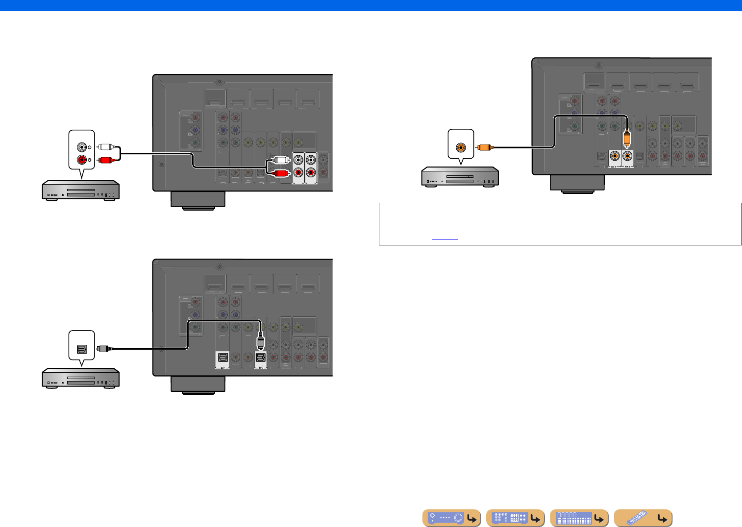
■
Connecting CD players and other audio devices
Using analog stereo output sources
Select the audio input (AUDIO1-2) that the external device is connected to for playback.
Using optical digital output sources
Select the AV input (AV1 or AV4) that the external device is connected to for playback.
Using coaxial digital output sources
Select the AV input (AV2 or AV3) that the external device is connected to for playback.
AUDIO 1
AUDIO 2
C
OMPONEN
T
VIDE
O
P
R
P
B
Y
OPTICAL
(
TV
)
AV 1
AV 2
AV 3
AV 4
AV 5
CO
AXIAL
(
CD
)
CO
AXIA
L
O
PTI
C
A
L
VIDE
O
HDMI
1
(
B
D/DVD
)
HDMI 2
HDMI
3
HDMI 4
CO
MP
O
NENT
VIDE
O
MO
NIT
O
R
OU
T
P
R
P
B
Y
HDM
I
OUT
M
O
NIT
O
R
OU
T
AV
OU
T
AUDI O
OUT
AUDIO
R
L
R
L
Audio output
CD player
OPTICAL
TV
OPTICAL
C
OMPONEN
T
VIDE
O
P
R
P
B
Y
AV 2
AV 3
AV 5
AUDIO 1
AUDIO 2
CO
AXIAL
(
CD
)
CO
AXIA
L
VIDE
O
HDMI
1
(
B
D/DVD
)
HDMI 2
HDMI
3
HDMI 4
CO
MP
O
NENT
VIDE
O
MO
NIT
O
R
OU
T
P
R
P
B
Y
HDM
I
OUT
M
O
NIT
O
R
OU
T
AV
OU
T
AUDI O
OUT
O
O
OPTICAL
CD player
Audio (Optical) output
We recommend connecting audio devices with an coaxial digital output to the AV3 coaxial digital
jack on this unit. This connection allows you to switch to the AV input 3 just by pressing the “CD”
SCENE key (☞
p. 26).
COAXIAL
(
CD
)
COAXIAL
C
OMPONEN
T
VIDE
O
P
R
P
B
Y
OPTICAL
(
TV
)
AV 1
AV 4
AV 5
AUDIO 1
AUDIO 2
O
PTI
C
A
L
VIDE
O
HDMI
1
(
B
D/DVD
)
HDMI 2
HDMI
3
HDMI 4
CO
MP
O
NENT
VIDE
O
MO
NIT
O
R
OU
T
P
R
P
B
Y
HDM
I
OUT
M
O
NIT
O
R
OU
T
AV
OU
T
AUDI O
OUT
C
C
COAXIAL
Audio (Coaxial) output
CD player
En 19
CONNECTIONS
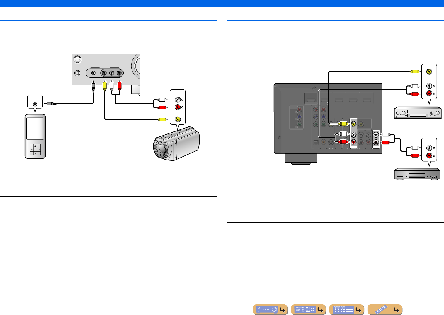
Connecting external devices
Connecting video cameras and portable audio players
Use the VIDEO AUX jacks on the front panel to temporarily connect video cameras, game consoles, or
portable audio devices to the receiver.
Select the V-AUX input to use these connected devices.
Transmitting input A/V to external devices
This receiver can transmit selected incoming analog audio/video signals to external devices through the
AV OUT and AUDIO OUT jacks. You can record these input audio and video signals to VCRs or
similar devices, or send them to other TVs or external devices.
Using the AV OUT jacks
Connect this jacks to the external device’s video input jack and analog audio input jacks.
Using the AUDIO OUT jacks
Connect this jack to the external device’s analog audio input jacks.
•Be sure to turn down the volume when connecting this unit and the other devices.
•When external components are connected to both the PORTABLE jack and the AUDIO jacks, the sound
output from the PORTABLE jack is transmitted.
VIDEO
AU X
STRAIGHT
RADIO
VIDEO
AUDIO
PORTABLE
LR
V
R
L
L
R
V
AU D I O
VIDEO
AUDIO OUT
Audio output
Portable audio playerVideo cameras
Audio output
Video output
HDMI audio/video signals, component video signals, and digital audio signals cannot be transmitted
from these jacks.
AV
OUT
AUDI O
OUT
CO
MP
O
NENT
VIDE
O
P
R
P
B
Y
O
PTI
C
AL
(
TV
)
AV1
AV 2
AV 3
AV 4
AV 5
AUDIO 1
AUDIO 2
CO
AXIAL
(
CD
)
CO
AXIAL
O
PTI
C
AL
VIDE
O
HDMI 1
(
BD
/
DV
D
)
HDMI
2
HDMI
3
HDMI
4
CO
MP
O
NEN
T
VIDE
O
MONITOR OUT
P
R
P
B
Y
HDMI
O
UT
MO
NIT
O
R
OU
T
AUDIO
VIDEO
R
L
V
AUDIO
R
L
R
L
V
R
L
Audio recorder
Audio input
VCR
Video / Audio
input
En 20
CONNECTIONS
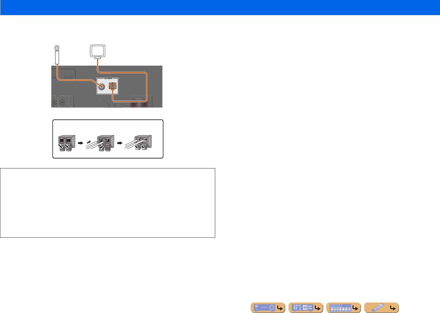
An indoor FM antenna and an AM loop antenna are included with this receiver. Connect these antennas
properly to their respective jacks.
Connecting the FM/AM antennas
■Improving FM reception
We recommend using an outdoor antenna. For more information, consult the nearest authorized
dealer.
■Improving AM reception
Connect this unit to an outdoor antenna with a 5-10 m vinyl-coated wire. Make sure the AM loop
antenna is still connected.
Connecting the GND jack can reduce noise. Connect the jack to a store-bought ground bar or copper
plate with a vinyl-covered wire and bury this new attachment in moist ground.
The GND jack is not to be connected to the ground socket of an electrical outlet.
FM
GND
AM
C
ENTER
SU
RR
OU
N
D
H
DMI
3
HDMI 4
F
R
O
NT
MONITOR OUT
S
PEAKER
S
Indoor FM antenna
AM loop antenna
Position the AM antenna away from the receiver. The
wires of the AM antenna have no polarity.
You can connect either wire to the AM jack or the
GND jack.
Connecting the AM loop antenna
ReleaseInsertPress and hold
En 21
CONNECTIONS
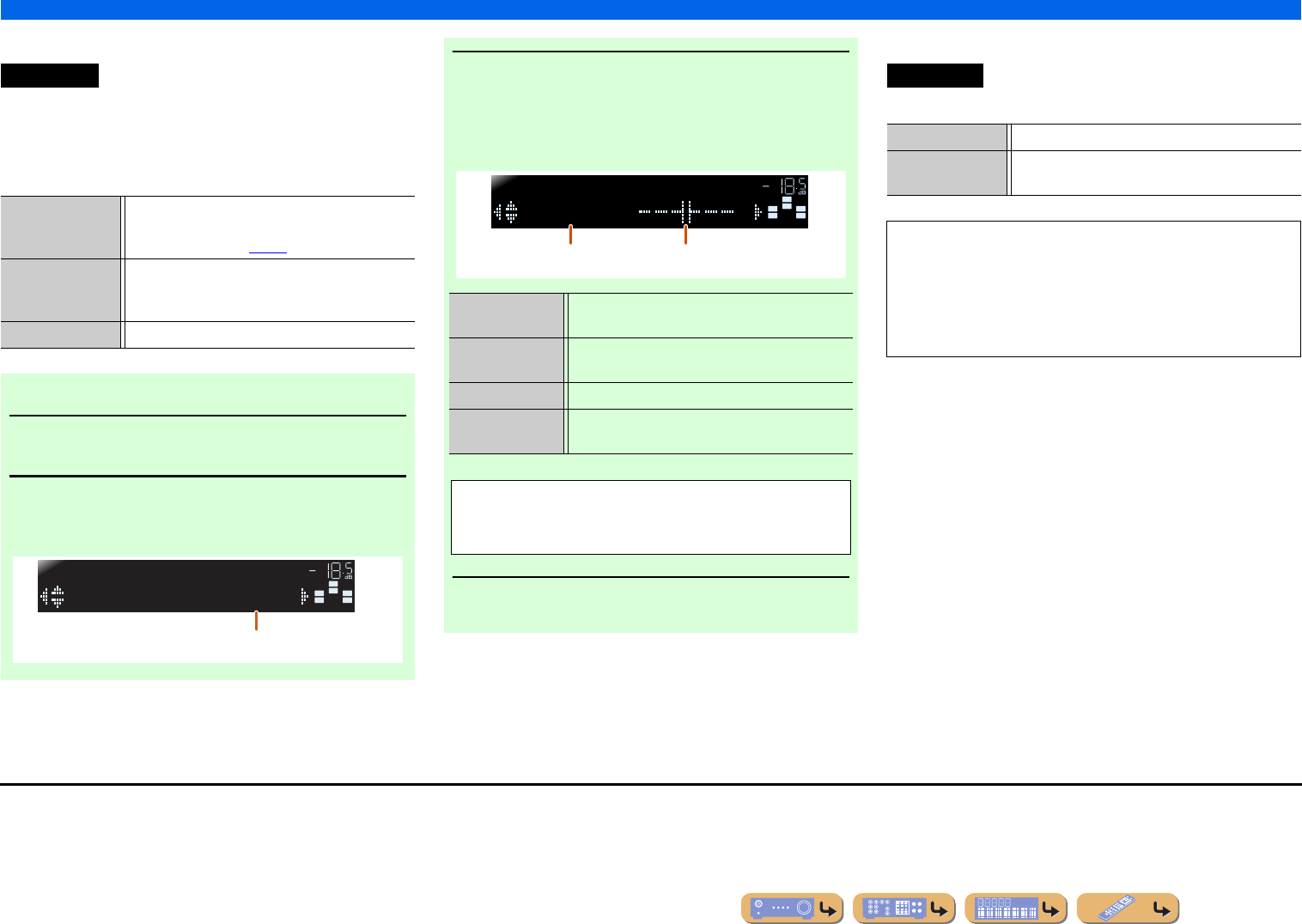
This unit is equipped with a YPAO (Yamaha Parametric Room Acoustic Optimizer) that adjusts the status, size, and volume balance of the speakers in order to provide an optimal sound field. Using
YPAO allows you to automatically configure settings for which specialist knowledge is usually needed, such as adjusting speaker output and acoustic parameters to suit your listening room (the room
in which this unit is placed). J1
1
Check the following before using YPAO.
This unit
•The headphones are removed.
Subwoofer
•The power is turned on.
•Volume is set to approximately half, and the cross-over frequency (if
present) is set to maximum.
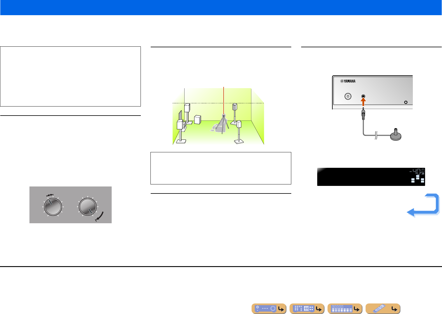
2
Place the supplied YPAO microphone at ear height in
your listening position.
Face the head of the YPAO microphone upwards.
3
Switch this unit on.
4
Connect the YPAO microphone to the YPAO MIC jack
on the front panel.
“MIC ON. YPAO START” appears on the front panel display, and
then changes to display the following. J2
Set up the speaker parameters automatically (YPAO)
When you use YPAO, a test tone will be output from the
speakers for approximately three minutes and acoustic
measuring will be performed. When using YPAO, be careful of
the following.
•The test tone is output at high volume. Please refrain from using
this function at night when it may be a nuisance to others nearby.
•Please take care that the test tone does not frighten any small
children.
VOLUME
MINMAX
CROSSOVER/
HIGH CUT
MINMAX
Subwoofer examples
When positioning the microphone, we recommend that you use
equipment that allows you to adjust the height (such as a tripod)
as a microphone stand. When using a tripod, use the tripod
screws to fix the microphone in place.
YPAO microphone
INFO
YPAO MIC
VOL.
SW
C
L
SLSR
R
Press[SETUP]
YPAO
Continues to the
next page
J
1 :When you have changed the number of speakers or the locations in which they
are installed, first use YPAO to adjust the speaker balance.
J
2 :To cancel measurement, disconnect the YPAO microphone.
En 22
CONNECTIONS
Set up the speaker parameters automatically (YPAO)
5
Press hSETUP to start measurement.
The following display appears if measurement finishes
without any problems.
6
Press iENTER to apply the results of
measurement.
7
Remove the YPAO microphone.
YPAO finishes automatically when the YPAO
microphone is removed.
SETUP
ENTER
R
ECEIVER
SC
ENE
O
PTION
RETURN
VO
L
U
M
E
ENHAN
C
E
R
SU
R. DE
CO
DE
S
TRAI
G
HT
H
DMI
AV
A
UDI
O
TRAN
S
MIT
S
LEE
P
1
2
3
4
1
2
3
4
1
2
5
V-A
U
X
TUNER
FM
I
NF
O
M
EM
O
RY
AM
P
RE
S
ET
T
U
NIN
G
MO
VIE
MUS
I
C
S
TERE
O
B
D
D
VD
TV
CD
RADI
O
MU
T
E
i
h
hSETUP
iCursorC / D / E
iENTER
This completes preparations. To achieve more
accurate results, be careful of the following when
measuring.
•Measuring will take approximately three minutes.
Keep the room as quiet as possible during
measurement.
•Wait in the corner of the listening room during
measurement or leave it entirely, to avoid becoming an
obstruction between the speakers and the YPAO
microphone.
NOTE
When a problem occurs, an error message or report
appears either during or after measurement. Use the
following page as a reference to solve the problem,
and carry out YPAO again.
VOL.
SW
C
L
SLSR
R
Progress00%
YPAO
Display during measurement
VOL.
SW
C
L
SLSR
R
YPAOComplete
YPAO
You can use the following method to cancel
measurement results if you want to redo the
measuring. Press iCursorC to switch to the
following display, the use iCursorD / E to select
“Cancel” and press iENTER. After this operation,
use the same procedure to carry out YPAO again.
The YPAO microphone is sensitive to heat. When you
have finished measuring, store the microphone out of
direct sunlight, and away from locations that may
experience high temperatures, such as on top of AV
equipment.
SW
C
L
SLSR
R
Disconnect MIC
YPAO
VOL.
SW
C
L
SLSR
R
Set>Cancel
YPAO
VOL.
En 23
CONNECTIONS
Set up the speaker parameters automatically (YPAO)
■
When an error message appears
during measurement
Check the content of the message from the list of
messages (☞
p. 24) to resolve the problem, and carry out
the measurement process again.
Check the error code that appears in the display, and
carry out YPAO again by performing the following steps.
When “E-1” or “E-2” is displayed:
1
Press iENTER once, and then press
iCursorE to select “Exit.”
2
Press iENTER to finish YPAO, and set the
unit to standby mode.
3
Check that the speakers are properly
connected.
4
Turn on the unit, and then carry out YPAO
again.
When “E-5” to “E-9” is displayed:
1
Check that the environment is suitable for
accurate measurement.
2
Press iENTER to switch the display.
3
Check that “Retry” is selected, and then
press iENTER to carry out YPAO again.
When “E-10” is displayed:
1
Press iENTER once, and then press
iCursorE to select “Exit.”
2
Press iENTER to finish YPAO.
3
Switch the unit to standby mode.
4
Turn on the unit again, and then carry out
YPAO.
■
When a warning message appears
after measurement
Check the content of the message from the list of
messages (☞
p. 24) to resolve the problem. You can
confirm the speaker that has the problem when that
speaker’s indicator lights up.
When multiple warning messages appear:
Use iCursorD / E to display other warning messages.
When applying the results of measurement:
Press iENTER to switch display, the use iCursorD
/ E to select “Set” and press iENTER.
When cancelling YPAO:
Press iENTER to switch display, the use iCursorD
/ E to select “Cancel” and press iENTER.
ENTER
R
ECEIVER
SC
ENE
O
PTION
S
ET
UP
RETURN
VO
L
U
M
E
ENHAN
C
E
R
SU
R. DE
CO
DE
S
TRAI
G
HT
H
DMI
AV
A
UDI
O
TRAN
S
MIT
S
LEE
P
1
2
3
4
1
2
3
4
1
2
5
V-A
U
X
TUNER
FM
I
NF
O
M
EM
O
RY
AM
P
RE
S
ET
T
U
NIN
G
MO
VIE
MUS
I
C
S
TERE
O
B
D
D
VD
TV
CD
RADI
O
MU
T
E
i
iCursorD / E
iENTER
E-9:CANCEL
YPAO
VOL.
Error message (example)
NOTE
Although you can apply the results of measurement
when a warning message appears, doing so will not
provide optimal sound. We recommend you resolve
the problem and then carry out YPAO again.
SLSR
W-3:LEVEL
YPAO
VOL.
Warning message (example)Speaker that has a
problem.
En 24
CONNECTIONS
Set up the speaker parameters automatically (YPAO)
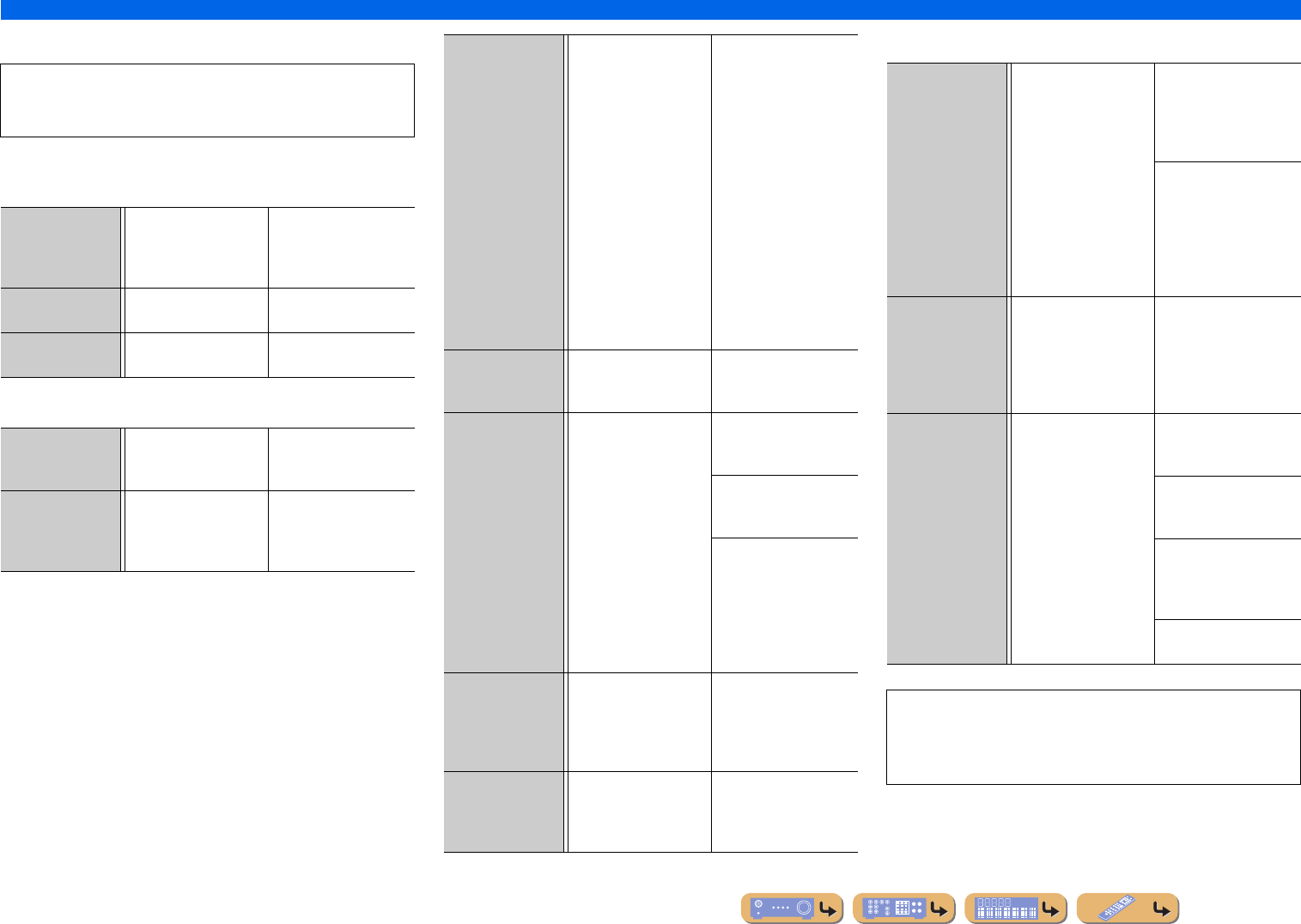
■
Message list
■When a warning message appears before
measurement
■Error message
■Warning message
NOTE
If the following messages appear, resolve the problems that have
occurred and carry out the measurement process again.
Connect MIC!The YPAO microphone is
not connected.
Connect the YPAO
microphone to the YPAO
MIC jack on the front
panel.
Unplug HP!The headphones are
connected.
Remove the headphones.
Memory Guard!The settings of this unit
are protected.
Set “Memory Guard” in
the Setup menu to “Off.”
E-1:FRONT SPThe unit was not able to
find the front channel.
Check that the left and
right front speakers are
connected correctly.
E-2:SUR. SPThe unit was only able to
find one of side of the
surround channels.
Check that the left and
right front surround
speakers are connected
correctly.
E-5:NOISYThe noise is too loud,
preventing accurate
measurements from
being taken.
Measure again in quiet
surroundings. Turn off any
devices in the room that
may be emitting noise, or
place them further away
from the YPAO
microphone.
When this message is
displayed, selecting
“Proceed” will allow you
to continue measuring.
However, we recommend
resolving the problem and
measuring again, as
continuing measurement
without doing so will not
give accurate results.
E-7:NO MICThe YPAO microphone
has been removed.
While measuring, take
care not to touch the
YPAO microphone.
E-8:NO SIGNALThe YPAO microphone
could not distinguish a
test tone.
Check that the YPAO
microphone has been
installed correctly.
Check that each speaker
has been connected and
installed correctly.
The YPAO microphone
or the YPAO MIC jack
may be broken. Inquire at
the retailer where you
purchased this unit, or the
nearest Yamaha service
center.
E-9:CANCELYou have carried out an
operation that has
cancelled the measuring
process.
Carry out the measuring
process again. Do not
operate this unit by, for
example, adjusting the
volume.
E-10:INTERNALAn internal error has
occurred.
Carry out the measuring
process again. Contact a
Yamaha service center if
“E-10” appears again.
W-1:PHASEThe speakers displayed
are connected with the
opposite polarity.
Depending on the type of
speakers you are using
and the environment in
which you have them
installed, this message
may occur even if the
speakers are connected
correctly.
Depending on the type of
speakers, “W-1” may
display even if the
speakers are connected
correctly.
Check that the speaker
polarity + (plus), and -
(minus) are correct. If
these are connected
correctly, you can use the
speakers normally even
this message appears.
W-2:OVER 24m
(80ft)
The speakers displayed
are separated from the
listening position by
more than 24m, and
cannot be adjusted
correctly.
Install the speakers with
24m of the listening
point.
W-3:LEVELThe difference each
channel is too loud or too
low, and cannot be
adjusted correctly.
Check that all speakers
are installed in the same
surroundings.
Check that the speaker
polarity + (plus), and -
(minus) are correct.
We recommend the same
speakers or speakers with
as similar specifications
as possible.
Adjust the volume of the
subwoofer.
If “W-2” or “W-3” appears, you can apply measurement results,
but they will not give optimal results. We recommend that you
resolve the problem and carry out the measurement process
again.
En 25
PLAYBACK
1
Turn on external components (TV, DVD
player, etc.) connected to this unit.
2
Turn on this unit and select the input source
using cInput selector.
The name of the selected input source is displayed for
a few seconds. J1
3
Play the external component that you have
selected as the source input, or select a
radio station on the tuner.
Refer to the instruction manuals provided with the
external component for details on playback.
For details on how to tune in to FM/AM stations, refer
to “FM/AM tuning” (☞
p. 30).
4
Press mVOLUME +/- to adjust the volume.
To mute the output.
Press nMUTE to mute the audio output.
Press nMUTE again to unmute.
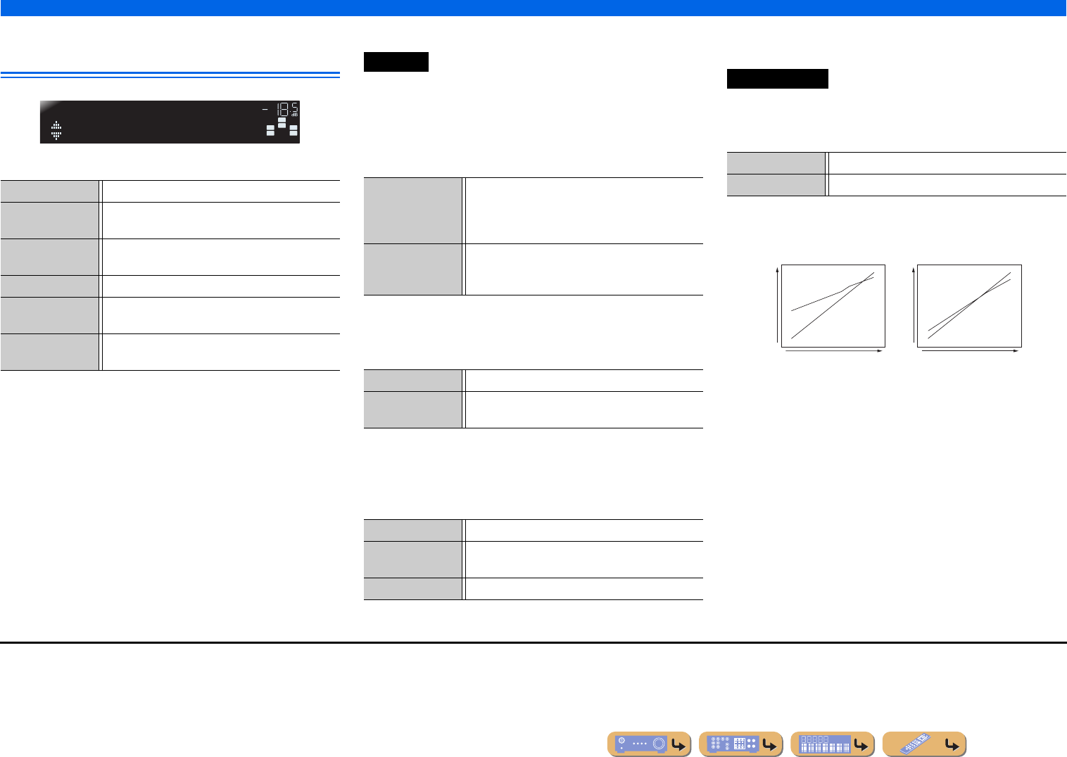
Adjusting high/low-frequency sound
(Tone control)
You can adjust the balance of the high-frequency range
(Treble) and low-frequency range (Bass) of sounds
output from the front left and right speakers to obtain
desired tone.
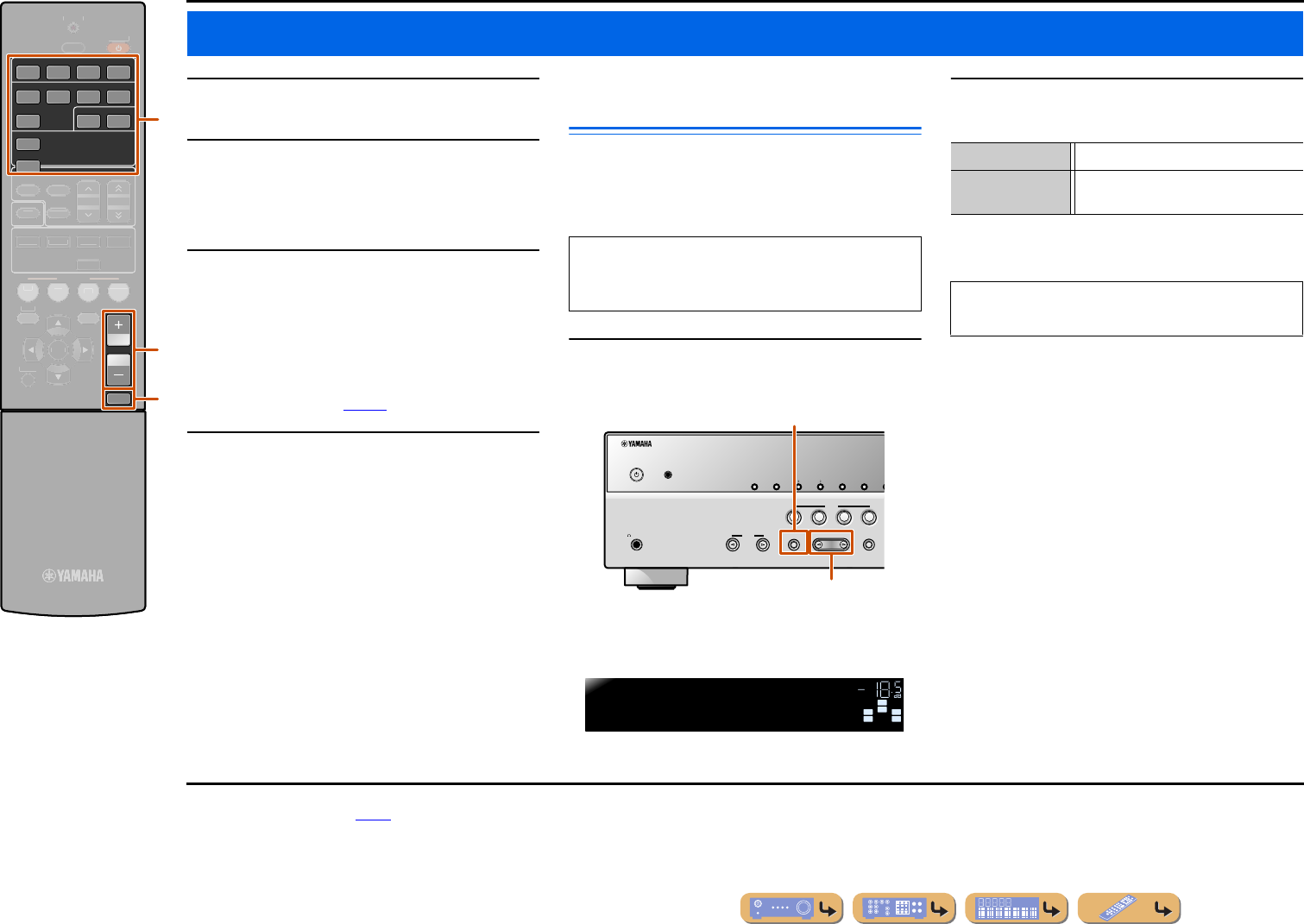
1
Press TONE CONTROL on the front panel
repeatedly to select “Treble” or “Bass.”
The current setting is displayed on the front panel
display.
2
Press PROGRAM l / h to adjust the output
level in those frequency ranges.
The display returns to the previous display soon after
you release the key.
Basic playback procedure
VOLUME
HDMI
AV
AUDIO
1234
1234
125
V-AUX
TUNER
MUTE
R
ECEIVER
SC
ENE
O
PTION
S
ET
UP
RETURN
ENHAN
C
E
R
SU
R. DE
CO
DE
S
TRAI
G
HT
TRAN
S
MIT
S
LEE
P
FM
I
NF
O
M
EM
O
RY
AM
P
RE
S
ET
T
U
NIN
G
MO
VIE
MUS
I
C
S
TERE
O
B
D
D
VD
TV
CD
RADI
O
ENTE
R
n
m
c
cInput selector
mVOLUME +/-
nMUTE
The tone control of the speakers or headphones can be
set separately. Set the headphone tone control with the
headphones connected.
PHONES
SILENT
CINEMA
TONE
CONTROL
STRAIGHT
TV
BD
DVD
CD
RADIO
INPUT
PROGRAM
SCENE
INFO
MEMORY
PRESET
FMAM
TONE CONTROL
PROGRAM l / h
YPAO MIC
SW
C
L
SLSR
R
SW
C
L
SLSR
R
Treble0.0dB
TONE
VOL.
Adjustable range-10.0 dB to +10.0 dB
Adjustment
increments
2.0 dB
If you set the balance extremely off, sounds may not
match those from other channels well.
J
1 :You can change the input source name displayed on the front
panel display as necessary (☞
p. 42).
En 26
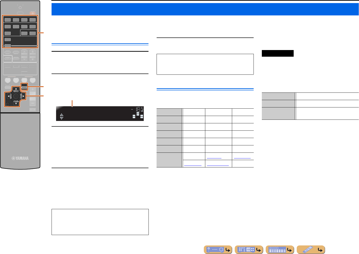
PLAYBACK
This unit has a SCENE function that allows you to turn the power on and change input sources and sound field programs with one key.
Four scenes are available for different uses, such as
playing movies or music. The following input sources
and sound field programs are provided as the initial
factory settings.
Registering input sources/sound
field program
1
Use cInput selector to select the input
source you want to register.
2
Use the fSound selection keys to select
the sound field program you want to
register.
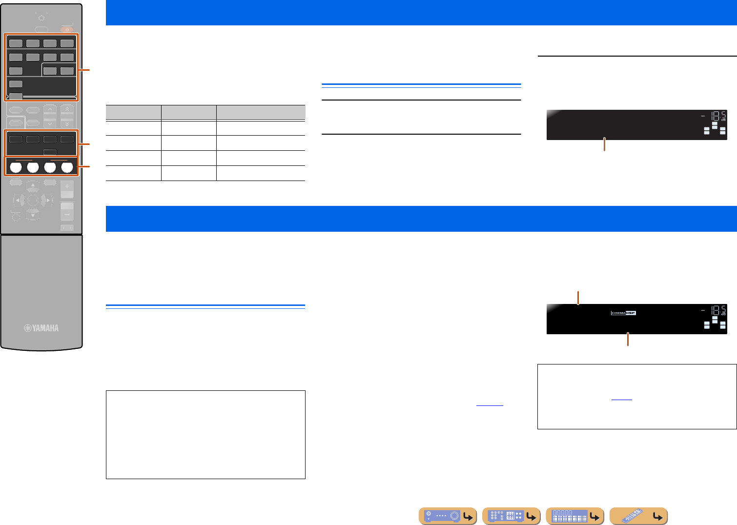
3
Press the gSCENE key until “SET
Complete” appears on the front panel
display.
This unit is also equipped with a Yamaha digital sound field processing (DSP) chip. You can enjoy multi-channel playback for almost any sound source using various
sound field programs stored on the chip, and a range of sound decoders.
Selecting sound field programs and
sound decoders
This unit offers sound field settings (sound field
programs) in many different categories suitable for
movies, music and other uses. Choose a sound field
program that sounds best with the source you are playing
back, rather than relying on the name or explanation of
the program.
Selects sound field program:
MOVIE category: Press fMOVIE repeatedly
MUSIC category: Press fMUSIC repeatedly
Selects stereo reproduction:
Press fSTEREO repeatedly
Selects compressed music enhancer:
Press fSTEREO repeatedly
Selects surround decoder:
Press fSUR. DECODE repeatedly
Switches Straight decoding mode (☞p. 27):
Press fSTRAIGHT
Changing input settings with a single key (SCENE function)
cInput selector
fSound selection keys
fMOVIE
fMUSIC
fSTEREO
fSUR. DECODE
fSTRAIGHT
gSCENE
SCENE
ENHANCER
SUR. DECODE
STRAIGHT
HDMI
AV
AUDIO
1234
1234
125
V-AUX
TUNER
MOVIEMUSIC
STEREO
BD
DVD
TV
CD
RADIO
R
ECEIVER
O
PTION
S
ET
UP
RETURN
VO
L
U
M
E
TRAN
S
MIT
S
LEE
P
FM
I
NF
O
M
EM
O
RY
AM
P
RE
S
ET
T
U
NIN
G
MU
T
E
ENTE
R
g
f
c
SCENEInputSound field program
BD/DVDHDMI1Straight
TVAV4Straight
CDAV3Straight
RADIOTUNER5ch Enhancer
SW
C
L
SLSR
R
SET Complete
SCENE1
VOL.
Release the key when “SET Complete” is displayed.
Enjoying sound field programs
•Sound field programs are stored for each input source.
When you change the input source, the sound field
program previously selected for that input source is
applied again.
•If the sampling frequency of an input source is higher
than 96 kHz, this unit does not apply any sound field
programs.
•You can use the speaker indicators on the front panel
display to check what speakers are currently
outputting sound (☞
p. 7).
•You can adjust sound field elements (sound field
parameters) for each of the programs.
SW
C
L
SLSR
R
Sci-Fi
MOVIE
VOL.
Sound field program categories
Program
En 27
PLAYBACK
Enjoying sound field programs
■
Enjoying unprocessed playback
(Straight decoding mode)
Use straight decoding mode when you want to playback
sound without sound field processing. You can playback
as follows in straight decoding mode.
2-channel sources such as CD
Stereo sound plays through the front left and right
speakers.
Multi-channel playback sources such as BD/
DVD
Plays back audio from a playback source without
applying sound field effects, using an appropriate
decoder to split the signal into multiple channels.
1
Press fSTRAIGHT to activate the straight
decoding mode.
2
Press fSTRAIGHT again to exit straight
decoding mode.
■
Enjoying stereo playback
Select “2ch Stereo” from the surround field programs
when you want to playback 2-channel stereo sound
(from the front speakers only), regardless of the
playback source.
Selecting “2ch Stereo” will playback as follows for the
playback of CD and BD/DVD sources.
2-channel sources such as CD
Stereo sound plays back through the front speakers.
Multi-channel sources such as BD/DVD
Playback channels other than the front channels in the
playback source are mixed with the front channels and
played back through the front speakers.
1
Press fSTEREO repeatedly to select “2ch
Stereo.”
2
To deactivate stereo playback, press any of
the fSound selection keys to select a
sound field program other than “2ch
Stereo.”
■
Enjoying sound field programs
without surround sound speakers
This unit allows you to use virtual surround speakers to
enjoy sound field surround effects, even without any
surround speakers (Virtual CINEMA DSP mode). You
can even enjoy surround sound presence with just a
minimal configuration of the front speakers only.
This unit will switch to Virtual CINEMA DSP mode
automatically when surround speakers are
unavailable. J1
■
Enjoying sound field programs
with headphones
Even when headphones are connected, you can enjoy the
reproduction sound field presence with ease (SILENT
CINEMA mode). J2
f
Sound selection keys
fSTRAIGHT
fSTEREO
ENHANCER
SUR. DECODE
STRAIGHT
MOVIEMUSIC
STEREO
R
ECEIVER
SC
ENE
O
PTION
S
ET
UP
RETURN
VO
L
U
M
E
H
DMI
AV
A
UDI
O
TRAN
S
MIT
S
LEE
P
1
2
3
4
1
2
3
4
1
2
5
V-A
U
X
TUNER
FM
I
NF
O
M
EM
O
RY
AM
P
RE
S
ET
T
U
NIN
G
B
D
D
VD
TV
CD
RADI
O
MU
T
E
ENTE
R
f
SW
C
L
SLSR
R
Straight
VOL.
SW
C
L
SLSR
R
Sci-Fi
MOVIE
VOL.
Previously selected program
SW
L
R
2ch Stereo
STEREO
VOL.
SW
C
L
SLSR
R
Hall in Vienna
MUSIC
VOL.
J
1 :However, Virtual CINEMA DSP mode is not available in the
following conditions:
•When headphones are connected to this unit.
•When a “2ch Stereo” sound field program is selected.
•When straight decoding mode is selected.
J
2 :However, SILENT CINEMA mode is not available in the
following conditions:
•When a “2ch Stereo” sound field program is selected.
•When straight decoding mode is selected.
En 28
PLAYBACK
Enjoying sound field programs
Sound field programs
■
Category: MOVIE
Sound field programs optimized for viewing video sources such as movies, TV programs, and games.
■
Category: MUSIC
This sound field is suitable when listening to music sources such as CDs.
in the table indicates the sound field program for CINEMA DSP.
StandardThis program creates a sound field emphasizing the surround feeling without disturbing the
original acoustic positioning of multi-channel audio such as Dolby Digital and DTS. It has
been designed with the concept of an ideal movie theater, in which the audience is
surrounded by beautiful reverberations from the left, right and rear.
SpectacleThis program represents the spectacular feeling of large-scale movie productions. It
reproduces a broad theater sound field that matches cinemascope and wider-screen movies
with an excellent dynamic range providing everything from very small sound effects to
large, impressive sounds.
Sci-FiThis program clearly reproduces the finely elaborated sound design of the latest science
fiction and special effects-featuring movies. You can enjoy a variety of cinematographically
created virtual spaces reproduced with clear separation between dialog, sound effects and
background music.
AdventureThis program is ideal for precisely reproducing the sound design of action and adventure
movies. The sound field restrains reverberations but puts emphasis on reproducing a
powerful space expanded widely to the left and right. The reproduced depth is also
restrained relatively to ensure the separation between audio channels and the clarity of the
sound.
DramaThis sound field features stable reverberations that match a wide range of movie genres from
serious dramas to musicals and comedies. The reverberations are modest but offer an
optimum 3D feeling, reproducing effects tones and background music softly but cubically
around clear words and center positioning in a way that does not fatigue the listener even
after long hours of viewing.
Mono MovieThis program is provided for reproducing monaural video sources such as a classic movie in
an atmosphere of a good old movie theater. The program produces the optimum expansion
and reverberation to the original audio to create a comfortable space with a certain sound
depth.
SportsThis program allows the listeners to enjoy stereo sport broadcasts and studio variety
programs with enriched live feeling. In sports broadcasts, the voices of the commentator and
sportscaster are positioned clearly at the center while the atmosphere of the stadium expands
in an optimal space to offer the listeners a feeling of presence in the stadium.
Action GameThis sound field is suitable for action games such as car racing and FPS games. It uses
reflection data that limits the effects range per channel in order to offer a powerful playing
environment that makes the listener feel as if they are right there by enhancing various
effects tones while maintaining a clear sense of directions.
Roleplaying GameThis sound field is suitable for role-playing and adventure games. It combines the sound
field effects for movies and the sound field designs for “Action Game” to represent the depth
and 3D feeling of the field during play, while offering movie-like surround effects in the
movie scenes in the game.
Hall in MunichThis sound field simulates a concert hall with approximately 2500 seats in Munich, using
stylish wood for the interior finishing as normal standards for European concert halls. Fine,
beautiful reverberations spread richly, creating a calming atmosphere. The listener’s virtual
seat is at the center left of the arena.
Hall in ViennaThis is an approximately 1700-seat, middle-sized concert hall with a shoebox shape that is
traditional in Vienna. Pillars and ornate carvings create extremely complex reflections from
all around the audience, producing a very full, rich sound.
ChamberThis program creates a relatively wide space with a high ceiling like an audience hall in a
palace. It offers pleasant reverberations that are suitable for courtly music and chamber
music.
Cellar ClubThis program simulates a live house with a low ceiling and homey atmosphere. A realistic,
live sound field features powerful sound as if the listener is in a row in front of a small stage.
The Roxy TheatreThis is the sound field of a rock music live house in Los Angeles, with approximately 460
seats. The listener’s virtual seat is at the center left of the hall.
The Bottom LineThis is the sound field at stage front in The Bottom Line, a famous New York jazz club once.
The floor can seat 300 people to the left and right in a sound field offering real and vibrant
sound.
Music VideoThis sound field offers an image of a concert hall for live performance of pop, rock and jazz
music. The listener can indulge oneself in a hot live space thanks to the presence sound field
that emphasizes the vividness of vocals and solo play and the beat of rhythm instruments,
and to the surround sound field that reproduces the space of a big live hall.
En 29
PLAYBACK
Enjoying sound field programs
■
Category: STEREO
Suitable for listening to stereo sources.
■
Category: ENHNCR (Compressed music enhancer)
Suitable for listening to compressed audio, such as MP3.
■
Category: SUR.DEC (Surround decode mode)
Select this program to playback sources with selected decoders. You can playback 2-channel sources as
5.1-channel sound.
2ch StereoUse this program to mix down multi-channel sources to 2 channels. When multi-channel
signals are input, they are down mixed to 2 channels and output from the front left and right
speakers.
5ch StereoUse this program to output sound from all speakers. When you play back multi-channel
sources, this unit down-mixes the source to 2 channels, and then outputs the sound from all
speakers. This program creates a larger sound field and is ideal for background music at
parties, etc.
Straight EnhancerUse this program to restore the original depth and dynamics of 2-channel or multi-channel
to compression audio.
5ch EnhancerUse this program to play back compression artifacts in 5-channel stereo.
q Pro LogicA Dolby Pro Logic decoder. Suitable for any source.
q PLII MovieA Dolby Pro Logic II decoder. Suitable for viewing any movie.
q PLII MusicA Dolby Pro Logic II decoder. Suitable for listening to music.
q PLII GameA Dolby Pro Logic II decoder. Suitable for playing games.
En 30
PLAYBACK
The FM/AM tuner of this unit provides the following
two modes for tuning.
Normal tuning
You can tune in to a desired FM/AM station by searching
or specifying its frequency.
Preset tuning (☞p. 31)
You can preset the frequencies of FM/AM stations by
registering them to specific numbers, and later just select
those numbers to tune in.
Selecting a frequency for reception
(Normal tuning)
1
Press cTUNER to switch to the tuner input.
2
Press dFM or dAM to select a band to
receive.
3
Use dTUNINGH / I to set a frequency to
receive.
dTUNINGH
Increases the frequency. Press and hold this key for
longer than a second to search automatically for a station
on a higher frequency than the current one. J1
d
TUNINGI
Decreases the frequency. Press and hold this key for
longer than a second to search automatically for a station
on a lower frequency than the current one. J1
FM/AM tuning
cTUNER
dFM
dAM
dTUNING H / I
iCursor B / C / D / E
iENTER
lOPTION
OPTION
TUNER
FMAM
TUNING
ENTER
R
ECEIVER
SC
ENE
S
ET
UP
RETURN
VO
L
U
M
E
ENHAN
C
E
R
SU
R. DE
CO
DE
S
TRAI
G
HT
H
DMI
AV
A
UDI
O
TRAN
S
MIT
S
LEE
P
1
2
3
4
1
2
3
4
1
2
5
V-A
U
X
I
NF
O
M
EM
O
RY
P
RE
S
ET
MO
VIE
MUS
I
C
S
TERE
O
B
D
D
VD
TV
CD
RADI
O
MU
T
E
l
i
c
d
When using the FM/AM tuner, adjust the direction of
the FM/AM antenna connected to this unit to get the
best reception.
SW
C
L
SLSR
R
FM87.50MHz
VOL.
STEREO
TUNED
SW
C
L
SLSR
R
FM98.50MHz
VOL.
Lights up when receiving
a broadcast from a station
Lights up when receiving
a stereo broadcast
■When signal reception is poor
When you are receiving an FM broadcast and cannot
obtain a stable stereo broadcast, you can force this
unit to receive in a monaural mode.
1
Press cTUNER to switch to the tuner
input.
2
Press lOPTION to display the Option
menu. J2
3
Use iCursorB / C to select “FM Mode.”
4
Press iENTER and use the iCursorD /
E to select “Mono.”
5
When setting is completed, press
lOPTION to close the Option menu.
To return this unit to its original settings, use the
same procedure to return the settings to “Stereo.”
FMMode
OPTION
VOL.
FMMode:Mono
9850
VOL.
J
1 :When searching for a station, release the key once the search has
started.
J
2 :See the section on “Configuring the settings specific for each
input source (Option menu)” for details on the Option menu
(☞
p. 34).
En 31
PLAYBACK
FM/AM tuning
Registering and recalling a
frequency (Preset tuning)
You can register up to 40 FM/AM stations as preset
stations. There are two methods of presetting stations,
“Auto Preset” and “Manual Preset.” Use one of these
methods to register stations.
■
Presetting FM stations
automatically (Auto Preset)
The tuner detects FM stations with strong signals and
registers up to 40 automatically.
1
Press cTUNER to switch to the tuner input.
2
Press lOPTION to display the Option
menu. J1
3
Use iCursorB / C to select “Auto Preset.”
4
Press iENTER, then press dPRESETF /
G or iCursorB / C to choose the present
number from which to start the Auto Preset
function.
Auto Preset will begin approximately 5 seconds after
you select a preset number.
If you do not select a preset number, Auto Preset will
begin approximately 5 seconds after “READY” is
displayed.
The Option menu closes automatically when presetting
is complete.J2
■
Registering stations manually
(Manual Preset)
Select stations by hand and register them as presets
individually.
1
Tune in to the station you wish to register,
referring to “Selecting a frequency for
reception (Normal tuning)” (☞
p. 30).
2
Use one of the following methods to
register the station you are currently
receiving.
■Registering to a preset number to which no
station is registered
Press dMEMORY for 2 seconds or longer.
The station will be registered automatically to the lowest
open preset number (or the next number after the one
registered most recently).
c
TUNER
dMEMORY
dPRESET F / G
iCursor B / C
iENTER
iRETURN
lOPTION
OPTION
RETURN
TUNER
MEMORY
PRESET
ENTER
R
ECEIVER
SC
ENE
S
ET
UP
VO
L
U
M
E
ENHAN
C
E
R
SU
R. DE
CO
DE
S
TRAI
G
HT
H
DMI
AV
A
UDI
O
TRAN
S
MIT
S
LEE
P
1
2
3
4
1
2
3
4
1
2
5
V-A
U
X
FM
I
NF
O
AM
T
U
NIN
G
MO
VIE
MUS
I
C
S
TERE
O
B
D
D
VD
TV
CD
RADI
O
MU
T
E
l
i
d
c
AM stations cannot be automatically registered. Use
manual station preset.
SW
C
L
SLSR
R
Auto Preset
OPTION
VOL.
To cancel registration, press iRETURN.
SW
C
L
SLSR
R
01:FM87.50MHz
READY
VOL.
Selecting a preset number
StatusFrequency
Preset number
SEARCHMEMORY
During Auto Preset
Search
Preset for stations
SW
C
L
SLSR
R
Auto Preset
FINISH
VOL.
When Auto Preset is complete
STEREO
TUNED
SW
C
L
SLSR
R
01:FM98.50MHz
MEMORY
VOL.
Registered frequencies
JJ
1 :See the section on “Configuring the settings specific for each
input source (Option menu)” for details on the Option menu
(☞
p. 34).
J
2 :The preset with the lowest preset number will be selected
automatically immediately after presetting.
En 32
PLAYBACK
FM/AM tuning
■Designating a preset number for
registration
Press dMEMORY once, to display “Manual Preset” on
the front panel display. After a small wait, the preset
number that the station has been registered to will
appear.
Press dPRESETF / G to select the preset to register
the station to, and then press dMEMORY to register.
■
Recalling a preset station
You can call preset stations registered by automatic
station preset or manual station preset. J1
■To select a registered station
Press dPRESETF / G to select the preset
number of the station.
Clearing preset stations
1
Press cTUNER to switch to the tuner input.
2
Press lOPTION to display the Option
menu. J2
3
Use iCursorB / C to display “Clear
Preset” and press iENTER.
4
Use iCursorB / C to select the preset
number you want to clear, and press
iENTER to clear it.
5
Press lOPTION to finish this operation.
Radio Data System tuning
Radio Data System is a data transmission system used by
FM stations in many countries. This unit can receive
You can display the 4 types of the Radio Data System
information: “Program Service,” “Program Type,”
“Radio Text,” “Clock Time.”
1
Tune into the desired Radio Data System
broadcasting station.
cTUNER
dMEMORY
dPRESET F / G
iCursor B / C
iENTER
iRETURN
lOPTION
OPTION
RETURN
TUNER
MEMORY
PRESET
ENTER
R
ECEIVER
SC
ENE
S
ET
UP
VO
L
U
M
E
ENHAN
C
E
R
SU
R. DE
CO
DE
S
TRAI
G
HT
H
DMI
AV
A
UDI
O
TRAN
S
MIT
S
LEE
P
1
2
3
4
1
2
3
4
1
2
5
V-A
U
X
FM
I
NF
O
AM
T
U
NIN
G
MO
VIE
MUS
I
C
S
TERE
O
B
D
D
VD
TV
CD
RADI
O
MU
T
E
l
i
d
c
To cancel registration, press iRETURN or do not
operate the remote control for about 30 seconds.
SW
C
L
SLSR
R
01:Empty
9850
VOL.
Preset number
The newly registered frequency
Empty, or the frequency registered
most previously.
Blinks
Press iRETURN to cancel the operation.
Repeat this operation to clear the registration of
multiple numbers.
SW
C
L
SLSR
R
01:FM98.50MHz
CLEAR
VOL.
The number of the preset to be cleared
BlinksRegistered frequencies
The Radio Data System reception feature is only
available in U.K. and Europe models.
We recommend that you use the automatic preset
tuning to tune into the Radio Data System
broadcasting stations (☞
p. 31).
Continues to the
next page
J
1 :Preset numbers to which no stations are registered will be
skipped. “No Presets” or “No Presets in Memory” is displayed
when there are no stations are registered.
J
2 :See the section on “Configuring the settings specific for each
input source (Option menu)” for details on the Option menu
(☞
p. 34).
En 33
PLAYBACK
FM/AM tuning
2
Press eINFO repeatedly until the desired
information is displayed.
Information on the display changes as you press the
key. The kind of information is displayed for a while
and then the information is displayed. J1
Contents of information are as follows.
Front panel display (When “Program Type”
selected)
■
Automatic traffic information
reception
When the tuner is active, this unit can automatically
search for and receive transmissions from traffic
information broadcast stations. To enable this function:
1
Press cTUNER to switch to the tuner input.
2
Press lOPTION to display the Option
menu. J2
3
Use iCursorB / C to select
“TrafficProgram.”
4
Press iENTER to enable the search
function.
When a traffic station is found, it will appear on the
display and the Option menu will close.
OPTION
RETURN
TUNER
INFO
ENTER
R
ECEIVER
SC
ENE
S
ET
UP
VO
L
U
M
E
ENHAN
C
E
R
SU
R. DE
CO
DE
S
TRAI
G
HT
H
DMI
AV
A
UDI
O
TRAN
S
MIT
S
LEE
P
1
2
3
4
1
2
3
4
1
2
5
V-A
U
X
FM
M
EM
O
RY
AM
P
RE
S
ET
T
U
NIN
G
MO
VIE
MUS
I
C
S
TERE
O
B
D
D
VD
TV
CD
RADI
O
MU
T
E
l
i
e
c
cTUNER
eINFO
iCursor B / C
iENTER
iRETURN
lOPTION
Type of informationDescription
Program ServiceDisplays the name of the Radio Data
System program service currently
being received.
Program TypeDisplays the type of the Radio Data
System program currently being
received.
Radio TextDisplays the information on the
Radio Data System program
currently being received.
Clock TimeDisplays the current time.
DSP ProgramDisplays the currently selected
sound field program.
Audio DecoderDisplays the currently selected
surround decoder.
ProgramServiceProgramTypeRadioText
ClockTime
DSPProgramAudioDecoder
(Frequency display)
“Program Service,” “Program Type,” “Radio Text”
and “Clock Type” do not appear when the radio
station does not provide the Radio Data System
service.
STEREO
TUNED
SW
C
L
SLSR
R
CLASSICS
10800
VOL.
Frequency
Program Type
SW
C
L
SLSR
R
VolumeTrim
OPTION
VOL.
SW
C
L
SLSR
R
TrafficProgram
OPTION
VOL.
•The transmission search will begin in approximately
5 seconds. Or, when the status indicator reads
“READY,” you can begin the search immediately by
pressing
iENTER.
•By pressing
iRETURN right before or during a
search, it will return to the Option menu.
•When the status is “READY,” use
iCursorB / C to
start a search in the specified direction.
iCursorB: Searches upward from the current
frequency.
iCursorC: Searches downward from the current
frequency.
If the receiver cannot find a traffic station, “TP Not
Found” will appear on the display, and the Option
menu will shortly close.
SW
C
L
SLSR
R
TrafficProgram
READY
VOL.
Status
STEREO
TUNED
SW
C
L
SLSR
R
TPFM101.30MHz
FINISH
VOL.
Traffic info broadcast station (Frequency)
J
1 :“PTY Wait,” “RT Wait,” or “CT Wait” may appear when Program
Type, Radio Text, or Clock Time is displayed. That shows this
unit is receiving data (or stopping receiving data). If the data is
receivable, the corresponding information is displayed after a
while.
J
2 :See the Setting the Option menu for Each Input Source section
(☞
p. 34) for more information on the Option menu.
En 34
SETUP
This receiver has a unique option menu specific for each type of input source, such as volume trim for compatible input sources, audio/video data display for signals from
external devices, and other frequently used menu items.
Option menu display and setup
1
Use the cInput selector on the remote
control to select the Option menu you wish
to display.
2
Press lOPTION.
The Option menu appears for the desired input source.
3
Select the desired control/setup item using
iCursorB / C and press iENTER.
The displayed Option menu items differ depending on
the input source.
For details, read the following Option menu items
section.
4
Select the desired menu item (or enable a
function) using iCursorB / C / D / E and
iENTER.
Parameters of the selected item are displayed. The
parameters you can set differ depending on the menu
items.
5
To close the Option menu, press lOPTION.
Option menu items
The following menu items are provided for each input
source.
■
Adjusting volume between input
sources
Input source:All
Reduces any change in volume when switching between
input sources by correcting volume differences in each
input source. You can adjust this parameter for each
input source.
Configuring the settings specific for each input source (Option menu)
cInput selector
iCursor B / C / D / E
iENTER
iRETURN
lOPTION
OPTION
RETURN
HDMI
AV
AUDIO
1234
1234
125
V-AUX
TUNER
ENTER
R
ECEIVER
SC
ENE
S
ET
UP
VO
L
U
M
E
ENHAN
C
E
R
SU
R. DE
CO
DE
S
TRAI
G
HT
TRAN
S
MIT
S
LEE
P
FM
I
NF
O
M
EM
O
RY
AM
P
RE
S
ET
T
U
NIN
G
MO
VIE
MUS
I
C
S
TERE
O
B
D
D
VD
TV
CD
RADI
O
MU
T
E
l
i
c
•You can also use iRETURN to return to the previous
screen or close the Option menu.
•Certain selected menu items may automatically close
the Option menu when their functions are enabled.
SW
C
L
SLSR
R
VolumeTrim
OPTION
VOL.
Option menu
For a few seconds after closing the Option menu, the
remote control keys may not function. If this occurs,
reselect the input source.
HDMI1-4Volume TrimAudio InSignal Info
AV1-2Volume TrimAudio InSignal Info
AV3-4Volume TrimSignal Info
AV5Volume Trim
AUDIO1-2Volume Trim
V-AUXVolume Trim
TUNERVolume TrimFM ModeAuto Preset
Clear PresetTrafficProgram
Volume Trim
Adjustable range-6.0 dB to 0.0 dB to +6.0 dB
Default setting0.0 dB
Adjustment
increments
0.5 dB steps
En 35
SETUP
Configuring the settings specific for each input source (Option menu)
■
Combining HDMI/AV1-2 input source
video and audio
Input source:HDMI1-4, AV1-2
Combines video from HDMI or AV input sources with analog/
digital audio inputs in situations such as:
–an external device is connected with an HDMI cable but cannot
transmit audio through HDMI
–an external device with component video output and analog audio
output (such as certain game consoles) are connected to the
system
To change assignments, select an input source (HDMI1-4 or AV1-2)
as the video input first, and then select audio input jacks in this
menu.
Set as follows according on the desired combination of audio input
jacks.
■
Displaying information on audio/video
signals
Input source:HDMI1-4, AV1-4
Displays information on digital audio and video signals on the
front panel display. You can display the signal information by
pressing iENTER on the menu item and using iCursorB / C.
Audio information
Video information
■
Changing FM mode (Stereo/Monaural)
Input source:TUNER
Sets this unit to automatically match FM broadcast frequencies in
stereo, or to convert the frequency to monaural (☞
p. 30).
■
Automatically presetting FM radio
stations
Input source:TUNER
Automatically detects radio stations in the FM frequency and
registers them as preset stations (☞
p. 31).
■
Clearing preset FM stations
Input source:TUNER
Clears the preset stations (☞p. 32).
■
Searching for traffic information
Input source:TUNER
Automatically searches for traffic information with the Radio Data
System (☞
p. 32).
Audio In
Audio inputsSettings method
Optical digital audio
input
Select AV1 or AV4. Connect the external component
audio cable to the optical jack for the selected input.
Coaxial digital audio
input
Select AV2 or AV3. Connect the external component
audio cable to the coaxial jack for the selected input.
Analog audio inputSelect one of AV5, AUDIO1, or AUDIO2. Connect
the external component audio cable to the audio jack
for the selected input.
•For details of settings, refer to “Receiving audio from other input
sources” (☞
p. 15) and “Component connections to analog audio
output devices” (☞
p. 16).
•To return audio inputs to their previous settings, display this item
again, and select the original input jack.
SW
C
L
SLSR
R
Audio;;;;;;AV1
HDMI1
VOL.
Assignable audio input jacks
Inputs that change the audio source
Signal Info
FORMATFormat of audio signals.
CHANThe number of input signal channels (front/surround/
LFE).
For example, if input signal channels are 3 front
channels, 2 surrounds and LFE, “3/2/0.1” is
displayed.
SAMPLThe sampling frequency of analog-to-digital
conversion.
B RATEThe bit rate of input signal per second.
V INFormat and resolution of video input signal.
V OUTFormat and resolution of video output signal.
V.MSG
(appears only
when an error
has occurred)
Error messages about HDMI signals and components.
Error message
HDCP ErrorHDCP authentication failed.
Device OverThe number of connected HDMI
components is over the limit.
SW
C
L
SLSR
R
DolbyD
FORMAT
VOL.
Menu item
Information
•“No Signal” is displayed when no signals are being received,
and “---” is displayed if this unit cannot recognize the incoming
signal.
•The bit rate may vary during playback.
FM Mode
Auto Preset
Clear Preset
TrafficProgram
En 36
SETUP
You can configure various function settings of this unit using the Setup menu.
Setup menu display and settings
1
Press hSETUP on the remote control.
2
Use the iCursorB / C to select the desired
menu and press iENTER.
Setup menu categories
Ex: Sound Setup menu
3
Use iCursorB / C to navigate the
submenus to find the desired setting and
press iENTER.
4
When multiple items appear, use iCursor
B / C to select the desired item.
5
Press iCursorD / E to change the setting.
You can change other items by repeating step 4 and 5.
6
Press hSETUP to exit the Setup menu.
Setup menu items
Setup menu
Setting various functions (Setup menu)
hSETUP
iCursor B / C / D / E
iENTER
iRETURN
SETUP
RETURN
ENTER
R
ECEIVER
SC
ENE
O
PTION
VO
L
U
M
E
ENHAN
C
E
R
SU
R. DE
CO
DE
S
TRAI
G
HT
H
DMI
AV
A
UDI
O
TRAN
S
MIT
S
LEE
P
1
2
3
4
1
2
3
4
1
2
5
V-A
U
X
TUNER
FM
I
NF
O
M
EM
O
RY
AM
P
RE
S
ET
T
U
NIN
G
MO
VIE
MUS
I
C
S
TERE
O
B
D
D
VD
TV
CD
RADI
O
MU
T
E
h
i
Speaker SetupManages settings for speakers.
Sound SetupManages settings for audio output.
Func. SetupManages settings to make receiver
operation easier, such as input source
labeling and auto-standby functions.
DSP ParameterSets parameters for sound field programs.
Memory GuardProtects settings against accidental
alteration.
SW
C
L
SLSR
R
SpeakerSetup
SETUP
VOL.
SW
C
L
SLSR
R
Lipsync
SOUND
VOL.
You can also use iRETURN to return to the
previous screen.
For a few seconds after closing the Setup menu, the
remote control keys may not function. If this occurs,
reselect the input source.
SW
C
L
SLSR
R
Audio;;;;;;Amp
HDMI
VOL.
Speaker Setup
Config Subwoofer
Front
Center
Sur. LR
Crossover
SWFR Phase
Extra Bass
Level
Distance
Equalizer
Test Tone
Sound Setup
Lipsync HDMI Auto
Auto
Manual
Adaptive DRC
D.Range
Max Volume
Init.Volume
HDMI Audio Out
Func. Setup
Input Rename
AutoPowerDown
Dimmer
DSP Parameter
Memory Guard
(speakers)
(unit and speakers)
(speakers and frequency
bands)
En 37
SETUP
Setting various functions (Setup menu)
Manages settings for speakers
Speaker Setup submenu
■
Manual speaker setup
Adjusts the output characteristics of the speakers based on
manually set parameters.
Subwoofer
Confirms the subwoofer.
Front
Selects the size (sound reproduction capacity) of the front
speakers. J2
Center
Selects the size of the center speakers.
Sur. LR
Selects the size of the surround speakers.
ConfigManually manages speaker configuration, such as
speaker size (sound production capacity), and bass
audio processing.
LevelManually adjusts the volume of each speaker.
DistanceManually adjusts the output of each speaker based on
distance to the listening point.
EqualizerSelects an equalizer to adjust speaker output
characteristics.
Test ToneGenerates test tones.
SW
C
L
SLSR
R
SpeakerSetup
SETUP
VOL.
Config
In the Config submenu, you can select the speaker size
characteristic (Large or Small). Select the size (sound
reproduction capacity) that matches your speakers.
When speaker size is set to “Small,” low-frequency components
of the speakers that you configured are produced from the
subwoofer (or from the front speakers if there is no subwoofer).
Yes (Default)Select this when you have a subwoofer connected.
During playback, the subwoofer will produce audio
from the LFE (low-frequency effect) channel and bass
audio from other channels. J1
NoneSelect this when you do not have a subwoofer
connected. The front speakers will produce audio
from the LFE (low-frequency effect) channel and bass
frequency audio from other channels.
Woofer diameter
•16 cm or larger → Large
•16 cm or smaller → Small
Small (Default)Select this for small speakers. The subwoofer will
produce front channel low-frequency
components. J3
LargeSelect this for large speakers. The front speakers will
produce all of the front channel frequency
components.
NoneSelect this when there is no center speaker. The front
speakers will produce center channel audio.
Small (Default)Select this when a small center speaker is connected.
LargeSelect this when a large center speaker is connected.
NoneSelect this when no surround speakers are connected.
The front speakers will produce surround channel
audio signals.
Small (Default)Select this when the surround speakers are small.
LargeSelect this when the surround speakers are large.
J
1 :Enabling the “Extra Bass” setting allows both the subwoofer and the front
speakers to produce bass audio.
J
2 :When “Subwoofer” is set to “None,” you can only choose “Large.” If the front
speaker setting is “Small” and you change “Subwoofer” to “None,” it will
automatically change to “Large.”
J
3 :Enabling the “Crossover” setting allows you to set the frequency components
of audio signals transmitted from the front speakers to the subwoofer.
En 38
SETUP
Setting various functions (Setup menu)
Crossover
Sets the lower limit of low-frequency component output from
speakers set to “Small.”
Audio with a frequency below that limit will be produced from the
subwoofer or the front speakers. J1
SWFR Phase
Sets the phase of the subwoofer if the bass audio is lacking or
unclear.
Extra Bass
Allows the front channel low-frequency components to be
produced exclusively by the subwoofer, or by both the subwoofer
and the front speakers.
■
Controlling the volume of each speaker
Separately adjusts the volume of each speaker. Use iCursorB /
C to select the desired speaker and adjust the volume with
iCursorD / E.
■
Manually setting speaker distance
Adjusts the timing at which the speakers produce audio so that
sounds from the speakers reach the listening position at the same
time.
Selecting adjustment units
Use iCursorB / C to display “Unit,” and then use iCursorD
/ E to choose the units of length (meters or feet).
Setting distances for each speaker
Use iCursorB / C to display the speaker you want to configure,
and then use iCursorD / E to set the distance from the speaker
to your listening position.
40Hz110Hz
60Hz120Hz
80Hz (Default)160Hz
90Hz200Hz
100Hz
NRM (Default)Does not change the subwoofer phase.
REVReverses the subwoofer phase.
OnThe subwoofer and the front speakers produce the
front channel low-frequency components.
Off (Default)Depending on the size of the front speakers, either the
front speakers or the subwoofer produce the front
channel low-frequency components.
When the “Subwoofer” is set to “None,” the “Extra Bass”
setting is disabled.
Level
FLFront speaker L
FRFront speaker R
CCenter speaker
SLSurround speaker L
SRSurround speaker R
SWFRSubwoofer
Adjustable range-10.0 dB to +10.0 dB
Default setting0 dB (FL / FR / SWFR)
-1.0 dB (C / SL / SR)
Adjustment
increments
0.5 dB
Distance
UnitSelects the distance unit (meters or feet).
Front LFront speaker L
Front RFront speaker R
CenterCenter speaker
Sur. LSurround speaker L
Sur. RSurround speaker R
SWFRSubwoofer
Adjustable range0.30 m to 24.0 m (1.0 ft to 80.0 ft)
Default setting3.00 m (10.0 ft) (Front L/Front R/SWFR)
2.60 m (8.5 ft) (Center)
2.40 m (8.0 ft) (Sur. L/Sur. R)
Adjustment
increments
0.10 m (0.5 ft)
J
1 :If your subwoofer has a volume control or a crossover frequency control, set
the crossover frequency to maximum and the volume to half (or slightly less).
En 39
SETUP
Setting various functions (Setup menu)
■
Adjusting sound quality with the equalizer
Adjusts sound quality of tone using a parametric or graphic
equalizer.
EQ Select
Select an equalizer type.
■
Generating test tones
Turns the test tone generator on or off.
Equalizer
PEQUses the parametric equalizer to adjust sound quality.
Selecting this setting applies the tone settings
obtained using YPAO (☞p. 21).J1
GEQ (Default)Uses the graphic equalizer to adjust sound quality. By
pressing iENTER, you can adjust the
characteristics of the graphic equalizer.
OffDoes not activate the equalizer.
■Adjusting the graphic equalizer
1
When “EQ Select” is displayed, use iCursorD / E
to select “GEQ” and press iENTER.
2
Check that “Channel” appears and use iCursor
D / E to select the speaker for which you want to
adjust the equalizer.
SW
C
L
SLSR
R
Channel;FRNTL
GEQ
VOL.
The speaker you are adjusting
3
Press iCursorC repeatedly to select the
frequency you want to adjust, then use iCursorD
/ E to adjust the volume.
Raising volume:Press iCursorE.
Lowering volume:Press
iCursorD.
4
When you have finished making adjustments,
press hSETUP to close the Setup menu.
SW
C
L
SLSR
R
63Hz
GEQ
VOL.
Frequency bandSetting the volume level for
the selected frequency
Frequency
range
63 Hz/160 Hz/400Hz/1kHz/2.5kHz/6.3kHz/
16 kHz
Adjustable
range
-6.0 dB to 0 dB to +6.0 dB
Default setting0 dB
Adjustment
increments
0.5 dB
You can use iCursorB / C to select another frequency or
return to step 2. Repeat steps 2-3 to adjust the tone to your
liking.
Test Tone
Off (Default)Does not generate test tones.
OnGenerates test tones. While “On” is selected, test
tones are produced constantly.
You can use the test tone in a variety of circumstances. For
example, you can adjust the volume balance settings for each
speaker, or whenever you adjust the settings on the internal
graphic equalizer, you can listen to the actual effect while
operating this unit. Turn the test tone off when you have finished
making adjustments.
J
1 :Using YPAO to carry out acoustic measurement selects “PEQ” automatically.
“PEQ” does not appear if the measurement process has not been carried out at
least once.
En 40
SETUP
Setting various functions (Setup menu)
Setting the audio output function of this
unit
Sound Setup submenu
■
Synchronizing audio/video output
Adjusts the delay between audio and video output (Lipsync
function).
HDMI Auto
When connecting to a TV via HDMI, automatically adjusts output
timing if the TV supports an automatic lipsync function.
Auto
Fine-adjust the audio output timing by entering the correction time
provided when “HDMI Auto” is set to “On.”
Manual
Manually adjusts the correction time. Select this when the TV does
not support the automatic lipsync function or “HDMI Auto” is set
to “Off.”
■
Auto-adjusting the sound level to make
even low volumes more audible
Adjusts the dynamic range in conjunction with the volume level
(from minimum to maximum). When you play audio at night or at
low volumes, it is a good idea to set parameter to “Auto.” J1
When the auto function is enabled, it adjusts the dynamic range as
follows.
LipsyncAdjusts the delay between video and audio output.
Adaptive DRCAuto-adjusting the sound level to make even low
volumes more audible.
D.RangeSelects the dynamic range adjustment method for
digital audio playback.
Max VolumeSets the maximum volume for this receiver.
Init.VolumeSets the initial volume for when this receiver is turned
on.
HDMI Audio OutSelects audio signals received through the HDMI
input jack.
SW
C
L
SLSR
R
SoundSetup
SETUP
VOL.
Lipsync
Off (Default)Select this when the connected TV does not support
the automatic lipsync function or you do not wish to
use the automatic lipsync function. Set the correction
time in “Manual.”
OnSelect this when the TV supports the automatic
lipsync function. Fine-adjust the correction time in
“Auto.”
Adjustable range0 ms to 240 ms
Adjustment
increments
1 ms
Adjustable range0 ms to 240 ms
Adjustment
increments
1 ms
Default setting0 ms
Adaptive DRC
AutoAdjusts the dynamic range automatically.
Off (Default)Does not adjust the dynamic range automatically.
Auto
Off
Auto
Off
Input LevelInput Level
Volume: lowVolume: high
Output Level
Output Level
J
1 :The Adaptive DRC setting is also effective when you use headphones.
En 41
SETUP
Setting various functions (Setup menu)
■
Auto-adjusting Dolby Digital and DTS
dynamic range
Selects the dynamic range adjustment method for audio bitstream
(Dolby Digital and DTS) playback.
■
Setting the maximum volume
Sets a maximum volume level so that the audio is not played too
loudly. The default setting of +16.5 dB produces the highest
volume.
■
Setting the startup volume
Sets the initial volume for when this receiver is turned on. When
this parameter is set to “Off,” the volume is set at the level when the
receiver last entered standby mode. J1
■
Changing the output destination of HDMI
input audio signals
Choose whether to playback audio from an external component
such as a BD/DVD player connected via HDMI through this unit or
through a TV.
D.Range
Max (Default)Produces audio without adjusting the dynamic range.
STDSets the standard dynamic range suitable for home
use.
MinSets the dynamic range at the lowest level for
playback. This is useful for low-volume audio.
Max Volume
Adjustable range-30.0 dB to +15.0 dB / +16.5 dB (Maximum volume)
Default setting+16.5 dB
Adjustment
increments
5.0 dB
Init.Volume
Adjustable rangeOff, Mute, -80 dB to +16.5 dB
Default settingOff
Adjustment
increments
0.5 dB
HDMI Audio Out
Amp (Default)Outputs audio through this unit only. When this
setting is selected, the external component outputs an
audio format compatible with this unit.
TVOutputs audio through a TV only. When this setting is
selected, the external component outputs an audio
format compatible with the TV. J2
Amp+TVOutputs audio from the TV and this unit. When this
setting is selected, the external component outputs an
audio format compatible with this unit and TV.
J
1 :When you set the “Max Volume” at a lower level than “Init.Volume,” the “Max
Volume” setting has priority.
J
2 :When “TV” is selected, the speakers of this unit do not output sound.
En 42
SETUP
Setting various functions (Setup menu)
Making the receiver easier to use
Func. Setup submenu
■
Changing input source names
Changes the input source names to be shown on the front
panel display.
You can change an input source name by choosing from
a list of templates, or make one of your own.
SETUP
RETURN
ENTER
R
ECEIVER
SC
ENE
O
PTION
VO
L
U
M
E
ENHAN
C
E
R
SU
R. DE
CO
DE
S
TRAI
G
HT
H
DMI
AV
A
UDI
O
TRAN
S
MIT
S
LEE
P
1
2
3
4
1
2
3
4
1
2
5
V-A
U
X
TUNER
FM
I
NF
O
M
EM
O
RY
AM
P
RE
S
ET
T
U
NIN
G
MO
VIE
MUS
I
C
S
TERE
O
B
D
D
VD
TV
CD
RADI
O
MU
T
E
i
h
hSETUP
iCursor B / C / D / E
iENTER
iRETURN
Input RenameChanges the input source names.
AutoPowerDownGoes into standby mode.
DimmerSets the Brightness of the front panel
display.
Input Rename
■Selecting a template
1
Select “Input Rename” from the Setup
menu and press iENTER.
2
Select the input source that you want to
rename using iCursorB / C.
SW
C
L
SLSR
R
Func.Setup
SETUP
VOL.
SW
C
L
SLSR
R
HDMI1
HDMI1
VOL.
Renaming the input source
3
Use iCursorD / E to select a new name
from the following templates.
4
Confirm the new display name by
pressing iRETURN. Press hSETUP to
exit the Setup menu.
To cancel a name change, select the original name
and then press
iRETURN to exit renaming.
■Entering an original name
1
Select “Input Rename” from the Setup
menu and press iENTER.
2
Select the input source that you want to
rename using iCursorB / C.
Blu-raySatellite
DVDVCR
SetTopBoxTape
GameMD
TVPC
DVRiPod
CDHD DVD
CD-R(blank)
SW
C
L
SLSR
R
HDMI1
HDMI1
VOL.
Renaming the input source
3
Press iENTER.
4
Use iCursorB / C to select the
characters you wish to change, and use
iCursorD / E to enter those characters.
The following characters are available for input
source.
•A to Z, a to z
•0 to 9
•Symbols (#, *, -, +, etc.)
•Space
5
Repeat step 4 until you have entered the
new input source name.
6
Confirm the new display name by
pressing iENTER. Press hSETUP to
exit the Setup menu.
To cancel a name change, press iRETURN.
SW
C
L
SLSR
R
HDMI1
HDMI1
VOL.
Cursor
En 43
SETUP
Setting various functions (Setup menu)
■
Goes enter standby mode automatically
when you leave it without operating
If you do not operate this unit or use the remote control for an
extended period of time, it will automatically go into standby mode
(Auto Power Down function). This function’s default setting is
“Off.” When you wish to activate this function, set the amount of
time to pass before this unit will enter standby.
■
Setting the brightness of the front panel
display
Sets the brightness of the front panel display. Lowering the setting
dims the display.
Setting sound field program parameters
You can set the parameters for the sound field programs (☞p. 44).
Prohibiting setting changes
Prohibits setting changes to prevent careless changes being made
to the settings on Setup menu.
AutoPowerDown
Off (Default)Auto Power Down function is disabled.
4hoursGoes into standby mode, when you have not operated
this unit for four hours.
8hoursGoes into standby mode, when you have not operated
this unit for eight hours.
12hoursGoes into standby mode, when you have not operated
this unit for twelve hours.
This unit starts a countdown of 30 seconds before entering the
standby mode. Pressing any key of the remote control during the
countdown cancels entering the standby mode and reset the
timer.
Dimmer
Adjustable range-4 to 0
Default setting0
Off (Default)Settings are not protected.
OnProhibits changes to the settings on Setup menu until
it is returned to “Off.”
While set to “On,” the unit displays “Memory
Guard!” when an attempt is made to change the
settings.
SW
C
L
SLSR
R
DSPParameter
SETUP
VOL.
SW
C
L
SLSR
R
Memory Guard
SETUP
VOL.
En 44
SETUP
Although the sound field programs would satisfy you as they are with the default parameters, you can arrange the effect by setting the sound field elements (parameters).
To adjust the sound effects suitable for acoustical conditions of audio/video sources or rooms, perform the following operations.
Setting sound field parameters
1
Press hSETUP to display the Setup menu.
2
Use iCursorB / C to select “DSP
Parameter” and press iENTER.
3
Use iCursorD / E to choose the sound
field program you want to edit.
4
Press iCursorB / C to select the
parameter that you want to change, and
press iCursorD / E to change the
parameter.
5
Once you have completed editing, press
hSETUP to close the Setup menu.
■
CINEMA DSP parameters
Change the effect level (level of the sound field effect to
be added). You can adjust the level of the sound field
effect while checking the sound effect.
Setting sound field program parameters
hSETUP
iCursor B / C / D / E
iENTER
SETUP
ENTER
R
ECEIVER
SC
ENE
O
PTION
RETURN
VO
L
U
M
E
ENHAN
C
E
R
SU
R. DE
CO
DE
S
TRAI
G
HT
H
DMI
AV
A
UDI
O
TRAN
S
MIT
S
LEE
P
1
2
3
4
1
2
3
4
1
2
5
V-A
U
X
TUNER
FM
I
NF
O
M
EM
O
RY
AM
P
RE
S
ET
T
U
NIN
G
MO
VIE
MUS
I
C
S
TERE
O
B
D
D
VD
TV
CD
RADI
O
MU
T
E
i
h
SW
C
L
SLSR
R
DSPParameter
SETUP
VOL.
SW
C
L
SLSR
R
Sci-Fi
DSPPRM
VOL.
Sound field program to be edited
When there are multiple parameters in the sound field
program you are configuring, repeat step 4 as
necessary to change other parameters.
■To initialize the sound field parameters
To set the parameters of the sound field program back
to default, press iCursorC repeatedly during
editing to select “Initialize” and press iCursorE.
When “Press Again >” is displayed, press iCursor
E again to initialize.
To cancel operations, press iCursorD when “Press
Again” appears and return to the original display.
SW
C
L
SLSR
R
DSPLevel;;0dB
DSPPRM
VOL.
Sound field parameterChoices
SW
C
L
SLSR
R
Initialize
DSPPRM
VOL.
DSP Level
Adjustable range-6 dB to 0 dB to +3 dB
Default setting0 dB
Adjust “DSP Level” as follows:
•The effect sound is too soft.
•There are no differences between effects of the sound
field programs.
→ Increase the effect level.
•The sound is dull.
•The sound field effect is added too much.
→ Reduce the effect level.
En 45
SETUP
Setting sound field program parameters
■
Parameters usable in certain sound field
programs
2ch Stereo only
Automatically bypasses the DSP circuit and tone control circuit
depending on the condition of tone control etc., when an analog
sound source is played back. You can enjoy a higher quality sound.
5ch Stereo only
Adjusts the center channel volume. J1
Adjusts the volume of the surround L channel. J1
Adjusts the volume of the surround R channel. J1
Straight Enhancer/5ch Enhancer only
Adjusts the effect level of the compressed music enhancer mode.
■
Parameters usable in surround decoder
q PLII Music only
Adjusts the soundscape of the front sound field. Sends front left/
right channels sounds to the surround speakers as well as the front
speakers for a wraparound effect.
Spreads the center channel sound to the front left and right
speakers to suit your needs or preferences. Set this parameter to 0
for outputting the center sound from the center speaker only, or to 7
for outputting it from the front left/right speaker only.
Adjusts the difference in level between the front sound field and
the surround sound field. You can adjust the difference in level
created by the software being played back to obtain the preferred
sound balance.
The surround sound gets stronger as you make the value more
negative, and the front sound gets stronger as you make the value
more positive.
Direct
Auto (Default)Outputs sound by bypassing the DSP circuit and tone
control circuit when both tone controls of “Bass” and
“Treble” are set to 0dB.
OffDoes not bypass the DSP circuit and tone control
circuit.
CT Level
Adjustable range0 to 100%
Default setting100%
SL Level
Adjustable range0 to 100%
Default setting100%
SR Level
Adjustable range0 to 100%
Default setting100%
EFCT LVL
High (Default)Standard effect.
LowSets when the high-frequency signals of the source are
emphasized excessively.
Panorama
Off (Default)Disables the effect.
OnEnables the effect.
CT Width
Adjustable range0 to 7
Default setting3
Dimension
Adjustable range-3 to STD to +3
Default settingSTD (Standard)
J
1 :Not displayed when speakers are set to be inactive.
En 46
SETUP
The Advanced Setup menu can be used for unit initialization and other useful extended functions. The Advanced Setup menu can be operated as follows.
Displaying/Setting the Advanced
Setup menu
1
Set this unit to the standby mode.
2
Press A while pressing and holding
STRAIGHT on the front panel.
Release the keys when “ADVANCED SETUP” is
displayed on the front panel display.
After approximately 3 seconds, the top menu items are
displayed.
3
Use PROGRAM to select the item to be set
from the following items.
In the Advanced Setup menu, you can set the following
settings.
4
Press STRAIGHT a few times to select the
value you wish to change.
5
Switch this unit to the standby mode, and
then switch it on again.
The settings become effective and the unit is powered
on. If initialization is selected, it will be performed
when the unit is powered on again.
Avoiding crossing remote control
signals when using multiple
Yamaha receivers
The remote control of the unit can only receive signals
from a receiver which has an identical ID (remote
control ID). When using multiple Yamaha AV receivers,
you can set each remote control with a unique remote
control ID for its corresponding receiver.
On the contrary, if you are setting the same remote
control ID for all receivers, you can use one remote
control to operate 2 receivers.
Initializing various settings for this
unit
Initializes various settings stored in this unit and sets it
back to default.
Select the items to be initialized from the following.
Extended functionality that can be configured as needed (Advanced Setup menu)
gSCENE
iCursor D
BD
DVD
TV
ENTER
RE
C
EIVER
E
NE
O
PTI
O
N
S
ET
UP
RETURN
VO
L
U
ME
E
NHAN
C
E
R
SU
R. DE
CO
DE
S
TRAI
G
HT
H
DMI
AV
A
UDI
O
TRAN
S
MI
T
S
LEE
P
1
2
3
4
1
2
3
4
1
2
5
V
-A
UX
T
UNE
R
FM
I
NF
O
M
EM
O
RY
A
M
PRE
S
ET
T
U
NIN
G
M
O
VIEM
US
I
C
S
TERE
O
CD
RADI
O
M
U
T
E
i
g
REMOTE IDChanges the remote control ID of a
receiver.
INITInitializes various settings for this unit.
PHONES
SILENT
CINEMA
TONE
CONTROL
STRAIGHT
TV
BD
DVD
CD
RADIO
INPUT
PROGRAM
SCENE
INFO
MEMORY
PRESET
FMAM
YPAO MIC
STRAIGHT
A
PROGRAM l / h
REMOTEID-ID1
ID1 (Default)Receives the remote control signals set in
ID1.
ID2Receives the remote control signals set in
ID2.
REMOTEID-ID1
■To change the remote control ID
•To set to ID1
Press
iCursorD and “BD/DVD” under gSCENE
for 3 seconds or longer.
•To set to ID2
Press
iCursorD and “TV” under gSCENE for
3 seconds or longer.
DSP PARAMInitializes all parameters for the sound
field programs.
ALLResets this unit to default factory settings.
CANCEL (Default)Does not initialize.
INIT-CANCEL
En 47
APPENDIX
Refer to the table below when this unit does not function properly.
If the problem you are experiencing is not listed below, or if the instructions below do not help, turn off this unit, disconnect the power cable, and contact the nearest authorized Yamaha dealer or service
center.
General
Troubleshooting
ProblemCauseRemedy
See
page
The power will not
turn on.
The protection circuitry operated
three times consecutively.
As a safety precaution, when the protection
circuitry operates three times consecutively,
the capability to turn on the power is
disabled. Please contact your nearest
Yamaha dealer or service center to request
repair.
—
The unit enters
standby mode soon
after the power is
turned on.
The power cable is not completely
inserted.
Connect the power cable properly to an AC
wall outlet.
—
(When this unit is turned back on
and “CHECK SP WIRES!” is
displayed.) The protection
circuitry has been activated
because this unit was turned on
while a speaker cable was shorted.
Make sure that all speaker cables between
this unit and speakers are connected
properly.
11
This unit cannot be
turned off or does
not work properly.
The internal microcomputer is
hung-up due to an external electric
shock (such as lightning or
excessive static electricity) or by a
drop in power supply voltage.
Disconnect the power cable from the AC
wall outlet, wait about 30 seconds and then
plug it in again.
—
The batteries in the remote control
may have lost their charge.
Replace all batteries.4
The unit enters
standby mode.
The protection circuitry has been
activated because of a short circuit,
etc.
Check that the speaker with an impedance
of at least 6Ω.
—
After display of a
countdown on the
front panel, the unit
goes into standby
mode.
If you do not use take any action,
the Auto Power Down function
operates.
Turn on the unit, and play the source again.—
In the Setup menu “AutoPowerDown”
(“Func. Setup” → “AutoPowerDown”),
increase the time until switching to standby
mode, or turn off the Auto Power Down
function.
43
“Internal Error” is
displayed on the
front panel display.
An internal error has occurred.Please contact authorized Yamaha dealer or
service center to request repair.
—
Sound/images
suddenly go off.
The protection circuitry has been
activated because of a short circuit,
etc.
Check that the speaker wires are not
touching each other, then turn the unit back
on.
—
The sleep timer has turned off the
unit.
Turn on the unit, and play the source again.—
ProblemCauseRemedy
See
page
En 48
APPENDIX
Troubleshooting
No sound.Incorrect input or output cable
connections.
Connect the cables properly. If the problem
persists, the cables may be defective.
15
If a DVI-HDMI cable is used to
connect the unit with an external
component, then it is necessary to
use an audio input jack for a
different input to output audio.
Display the HDMI Input Option menu for
the connected cable, select “Audio In,” and
select the jack to use for audio input.
35
Speaker connections are not
secure.
Secure the connections.11
The HDMI components connected
to the unit do not support the
HDCP copy protection standards.
Connect HDMI components that support the
HDCP copy protection standards.
35
The audio input into the device is
set to playback through the TV.
In the Setup menu, set the HDMI Audio Out
(“Sound Setup” → “HDMI Audio Out”) to
other than “TV.”
41
No appropriate input source has
been selected.
Select an appropriate input source with
cInput selector (on the remote control).
25
The volume is turned down or
muted.
Turn up the volume.—
Signals that this unit cannot
reproduce are being input from a
source component, such as a CD-
ROM.
Use an input source that has signals that can
be reproduced on this unit.
—
No picture.A video jack (ex. Video input →
HDMI output) type different to the
input video is being used to try to
display content on the TV.
Use video jacks of the same type (ex. Video
input → Video output) to connect to the TV.
13
An appropriate video input is not
selected on the TV.
Select an appropriate video input on the TV.—
ProblemCauseRemedy
See
page
No sound is output
from a specific
speaker.
The speaker is malfunctioning.
Check the Speaker indicators on
the front panel display. If the
corresponding indicator lights up,
connect another speaker and check
if sound is output.
If sound is not output, the unit may be
malfunctioning.
7
The playback component or
speakers are not connected
properly.
Connect the cables properly. If the problem
persists, the cables may be defective.
11, 15
Output from that speaker is
disabled.
Check the Speaker indicators on the front
panel display. If the corresponding indicator
is turned off, try the following.
1) Change to a different input source.
2) With the selected sound field program,
sound is not output from that speaker. Select
another sound field program.
3) “None” may have been selected for that
speaker on this unit. Display “Speaker
Setup” in the Setup menu, and set respective
parameters to enable output from that
speaker (“Speaker Setup” → “Config”).
7, 37
The volume of that speaker is set
to the minimum in “Speaker
Setup” in the Setup menu.
Display “Speaker Setup” in the Setup menu
and adjust the volume (“Speaker Setup” →
“Level”).
38
(If hardly any sound comes from
one channel)
Speaker output balance is not set
correctly.
Balance the volume of each speaker from
“Level” in the Setup menu (“Speaker Setup”
→ “Level”).
38
Sound may not be output from
certain channels, depending on the
input source or sound field
program.
Try another sound field program.26
Only the center
speaker outputs
substantial sound.
When a monaural source sound
field program is applied, for some
surround decoders, sound from all
channels is output from the center
speaker.
Try another sound field program.26
ProblemCauseRemedy
See
page
En 49
APPENDIX
Troubleshooting
HDMI™
No sound is heard
from the surround
speakers.
This unit is in straight decoding
mode and a monaural source is
being played back.
Press fSTRAIGHT (on the remote
control) to exit straight decoding mode.
27
Sound may not be output from
certain channels depending on
input sources or sound field
programs.
Try another sound field program.26
No sound is heard
from the subwoofer.
A subwoofer is not connected, or it
is disabled.
Check that a subwoofer is connected
correctly, and from the Setup menu
“Subwoofer” (“Speaker Setup” → “Config”
→ “Subwoofer”), set the subwoofer to
“On.”
37
The subwoofer is turned off.Turn the subwoofer power on.
If the subwoofer includes an Auto Power
Off function, then lower the Auto Power Off
sensitivity settings.
—
The source does not contain LFE
(☞p. 52) or low frequency signals.
—
The right
combination of audio
/ video jacks to
connect cannot be
found.
Combine input connected to the
external component video output
with another input audio jack.
Select a desired input source (HDMI1-4 or
AV1-2) as a video input and select a audio
input source from “Audio In” in the Option
menu.
35
The audio input
sources cannot be
played in the desired
digital audio signal
format.
The connected component is not
set to output the desired digital
audio signals.
Set the playback component properly
referring to its instruction manual.
—
This unit does not support
playback of HD Audio (TrueHD,
Dolby Digital plus, DTS Master
Audio, etc.) or DTS 96/24, etc.
Signals, such as HD Audio and DTS 96/24,
can be played by standard decoders (Dolby
Digital, DTS Digital Surround, etc.).
—
There is noise
interference from
digital or radio
frequency
equipment.
This unit is too close to other
digital or radio frequency
equipment.
Move this unit further away from such
equipment.
—
ProblemCauseRemedy
See
page
Noise/hum noise is
heard.
Incorrect cable connection.
Connect the audio cables properly.
If the problem persists, the cables may be
defective.
—
A DTS-CD is being played back.If a DTS bitstream signal is not properly
input to this unit, only noise is output.
Connect the playback component to this
unit by digital connection and play back the
DTS-CD.
If the condition is not resolved, the problem
may result from the playback component.
Consult the manufacturer of the playback
component.
—
The volume cannot
be increased, or the
sound is distorted.
The component connected to the
output jacks of this unit is not
turned on.
When the component connected to the
output jacks of this unit is not turned on, the
sound may be distorted, or the volume may
decreased due to the nature of AV receivers.
Turn on all components connected to this
unit.
—
“Max Volume” is set to a low
value.
Set it to a higher value.41
ProblemCauseRemedy
See
page
The front panel
display HDMI
indicator is flashing.
An error with the HDMI
connection has occurred.
Try re-inserting the HDMI cable.—
Confirm that HDMI video that is not
supported by the unit is not being input
(HDMI Input → Option menu → “Signal
Info”).
35
No picture or sound.The number of components is over
the limit.
Disconnect some of the HDMI components.—
The connected HDMI component
does not support high-bandwidth
digital copyright protection
(HDCP).
Connect an HDMI component that supports
HDCP.
—
ProblemCauseRemedy
See
page
En 50
APPENDIX
Troubleshooting
Tuner (FM/AM)
FMAM
ProblemCauseRemedy
See
page
FM stereo reception
is noisy.
You are too far from the station
transmitter, or the input from the
antenna is weak.
Check the antenna connections.20
Switch to monaural mode.30
Replace the outdoor antenna with a more
sensitive multi-element antenna.
—
There is distortion,
and clear reception
cannot be obtained
even with a good FM
antenna.
There is multi-path interference.Adjust the antenna height or orientation, or
place it in a different location.
—
The desired station
cannot be tuned into
with the automatic
tuning method.
You are in an area far from a
station, or input from the antenna
is weak.
Replace the outdoor antenna with a more
sensitive multi element antenna.
—
Use dTUNINGH / I (on the remote
control) to manually select the station.
30
“No Presets” is
displayed.
No preset stations are registered.Register stations you wish to listen to as
preset stations before operation.
31
ProblemCauseRemedy
See
page
The desired station
cannot be tuned into
with the automatic
tuning method.
The signal is weak, or the antenna
connections are loose.
Adjust the AM loop antenna orientation.20
Use the manual tuning method.30
Automatic station
preset does not
work.
Automatic station preset is not
available for AM stations.
Use manual station preset.31
Continuous
crackling and
hissing noises are
heard.
The supplied AM loop antenna is
not connected.
Connect the AM loop antenna correctly
even if you use an outdoor antenna.
20
The noises may be caused by
lightning, fluorescent lamps,
motors, thermostats, or other
electrical equipment.
It is difficult to completely eliminate noise,
but it can be reduced by installing and
properly grounding an outdoor AM antenna.
20
Buzzing and whining
noises are heard.
A TV set is being used nearby. Move this unit away from the TV set.—
En 51
APPENDIX
Troubleshooting
Remote control
ProblemCauseRemedy
See
page
The remote control
does not work or
function properly.
Wrong distance or angle. The remote control will function within a
maximum range of 6 m / 20 ft, and no more
than 30 degrees off-axis from the front
panel.
—
Direct sunlight or lighting (from
an inverter type of fluorescent
lamp, strobe light, etc.) is striking
the remote control sensor of this
unit.
Adjust the lighting angle, or reposition this
unit.
—
The batteries are weak.Replace all batteries.4
The remote control ID of the
remote control and this unit do not
match.
Match the remote control ID of this unit and
the remote control.
46
External components
cannot be controlled
using the remote
control.
The remote control code is not
correctly set.
If this unit does not work when you press
iCursorB / C / D / E (on the remote
control), do the following.
When the key does not work during DVD
disc menu operation: press the cInput
selector (on the remote control) again.
—
When the key does not work during Option
menu/Setup menu operation: press the key
corresponding to the current menu operation
again.
—
Even if the remote control code is correctly
set, there are some models that do not
respond to the remote control.
—
En 52
APPENDIX
Audio information
Audio and video synchronization (lip sync)
Lip sync, an abbreviation for lip synchronization, is a technical term that
involves both a problem, and the capability of maintaining audio and video
signals synchronized during post-production and transmission.
Whereas the audio and video latency requires complex end-user
adjustment, HDMI version 1.3 incorporates an automatic audio and video
syncing capability that allows devices to perform this synchronization
automatically and accurately without user interaction.
Dolby Digital
Dolby Digital is a digital surround sound system that gives you completely
independent multi-channel audio. With 3 front channels (front L/R and
center), and 2 surround stereo channels, Dolby Digital provides 5 full-range
audio channels. With an additional channel especially for bass effects,
referred to as LFE (Low-Frequency Effect), the system has a total of 5.1-
channels (LFE is counted as 0.1 channel). By using 2-channel stereo for the
surround speakers, more accurate moving sound effects and surround sound
environments are possible than with Dolby Surround. The wide dynamic
range from maximum to minimum volumes that are reproduced by the 5
full-range channels, and the precise sound orientation generated using
digital sound processing provides listeners with unprecedented excitement
and realism. With this unit, any sound environment from monaural up to a
5.1-channel configuration can be freely selected for your enjoyment.
Dolby Pro Logic II
Dolby Pro Logic II is an improved technique used to decode vast numbers
of existing Dolby Surround sources. This new technology enables a discrete
5-channel playback with 2 front left and right channels, 1 center channel,
and 2 surround left and right channels, instead of only 1 surround channel
for conventional Pro Logic technology. There are three modes available:
“Music mode” for music sources, “Movie mode” for movie sources, and
“Game mode” for game sources.
Dolby Surround
Dolby Surround uses a 4-channel analog recording system to reproduce
realistic and dynamic sound effects: 2 front left and right channels (stereo),
a center channel for dialog (monaural), and a surround channel for special
sound effects (monaural). The surround channel reproduces sound within a
narrow frequency range. Dolby Surround is widely used with nearly all
video tapes and laser discs, as well as in many TV and cable broadcasts.
The Dolby Pro Logic decoder built into this unit employs a digital signal
processing system that automatically stabilizes the volume on each channel
to enhance moving sound effects and directionality.
DTS Digital Surround
DTS Digital Surround was developed to replace the analog soundtracks of
movies with a 5.1-channel digital sound track, and is now rapidly gaining
popularity in movie theaters around the world. DTS, Inc. has developed a
home theater system so that you can enjoy the depth of sound and natural
spatial representation of DTS Digital Surround in your home. This system
Libble takes abuse of its services very seriously. We're committed to dealing with such abuse according to the laws in your country of residence. When you submit a report, we'll investigate it and take the appropriate action. We'll get back to you only if we require additional details or have more information to share.
Product:
Forumrules
To achieve meaningful questions, we apply the following rules:
First, read the manual;
Check if your question has been asked previously;
Try to ask your question as clearly as possible;
Did you already try to solve the problem? Please mention this;
Is your problem solved by a visitor then let him/her know in this forum;
To give a response to a question or answer, do not use this form but click on the button 'reply to this question';
Your question will be posted here and emailed to our subscribers. Therefore, avoid filling in personal details.
Register
Register getting emails for Yamaha RX-V367 at:
new questions and answers
new manuals
You will receive an email to register for one or both of the options.
Get your user manual by e-mail
Enter your email address to receive the manual of Yamaha RX-V367 in the language / languages: English as an attachment in your email.
The manual is 4,03 mb in size.
You will receive the manual in your email within minutes. If you have not received an email, then probably have entered the wrong email address or your mailbox is too full. In addition, it may be that your ISP may have a maximum size for emails to receive.
If you have not received an email with the manual within fifteen minutes, it may be that you have a entered a wrong email address or that your ISP has set a maximum size to receive email that is smaller than the size of the manual.
The email address you have provided is not correct.
Please check the email address and correct it.
Your question is posted on this page
Would you like to receive an email when new answers and questions are posted? Please enter your email address.