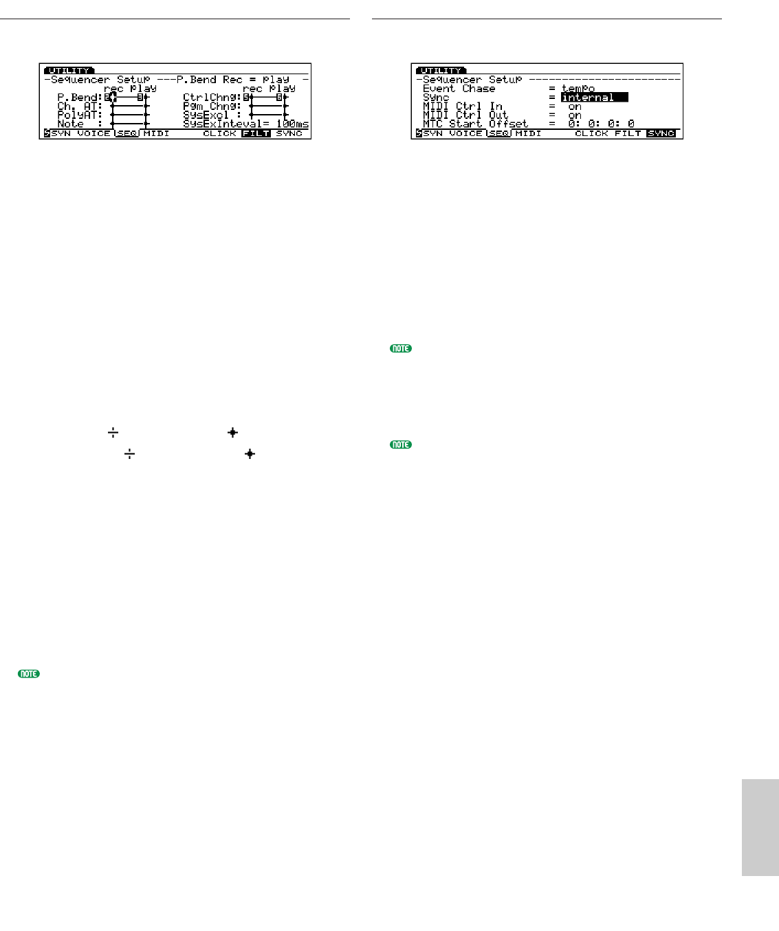
You can accomplish the breathing as you blow the Breath
Controller.
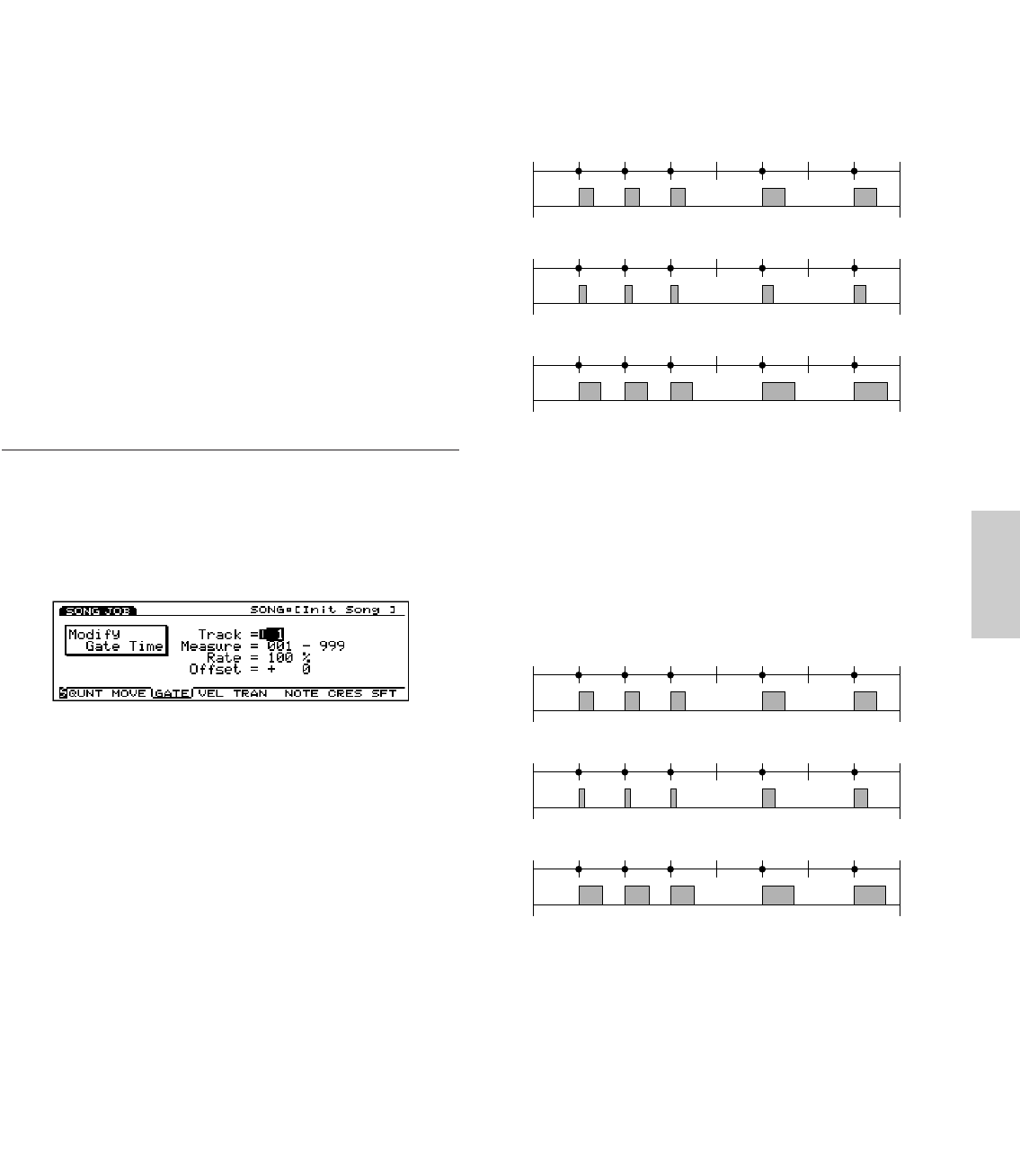
Velocity
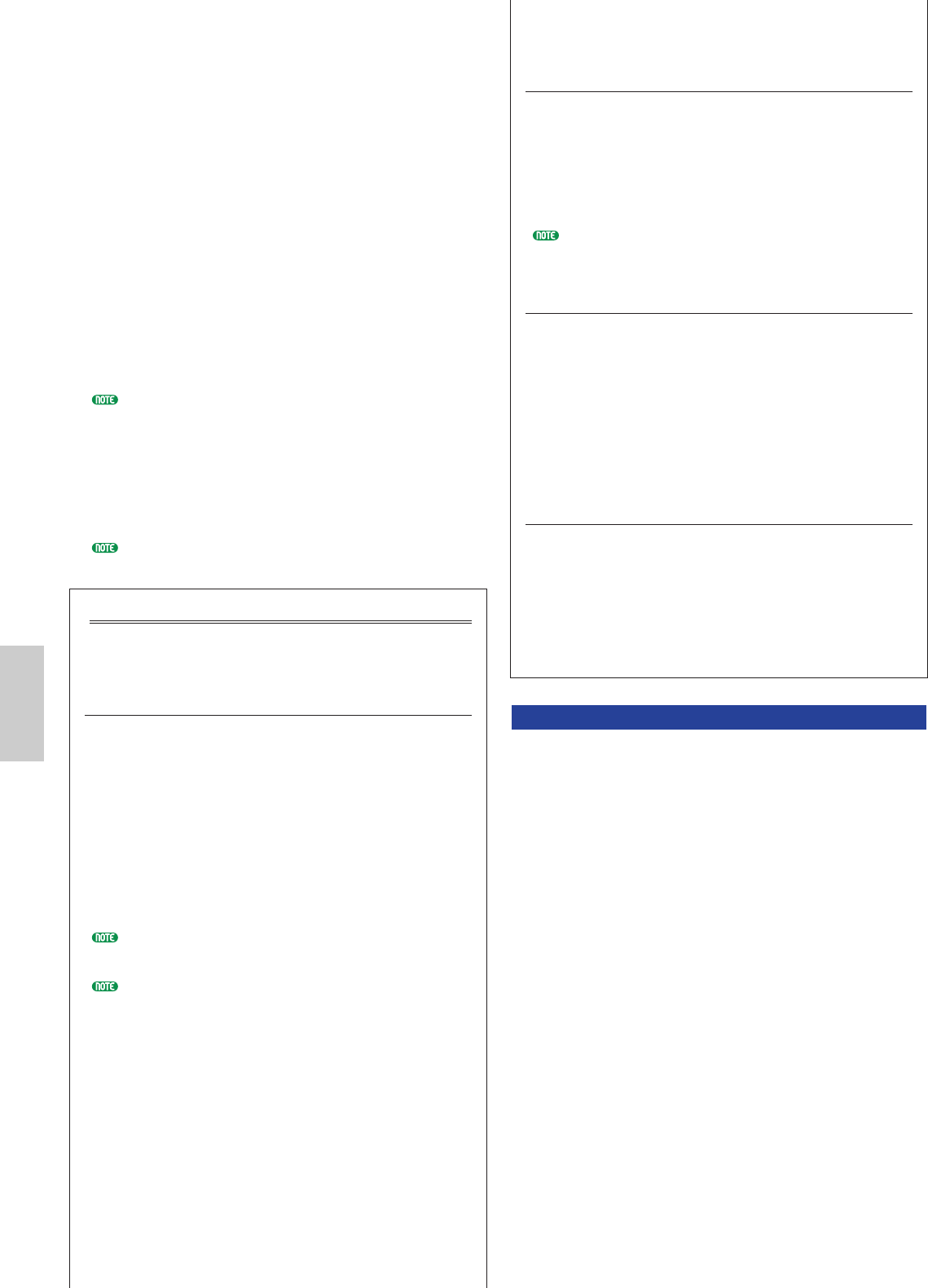
The initial attack determines the sustained breath strength
from the beginning through the end.
0
127
Breath
Control
Time
0
127
Breath
Control
Time
0
127
Breath
Control
Time
Utility/E/qx 5/21/98 11:54 AM Page 275
276
Utility Mode
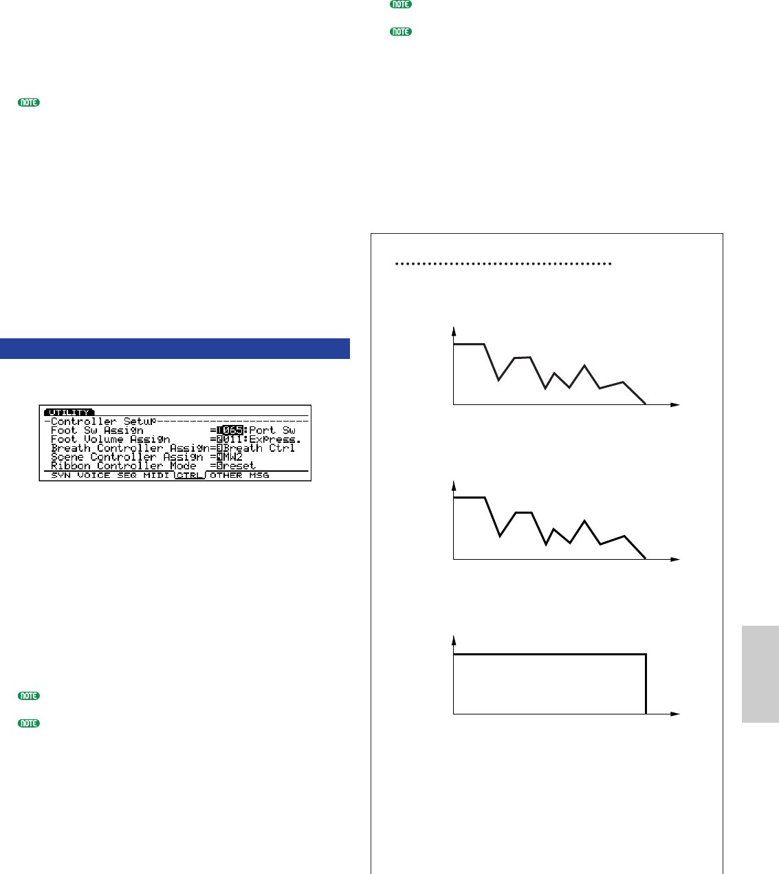
Touch EG
You can express the portion “A” with the velocity and “B”
with the aftertouch.
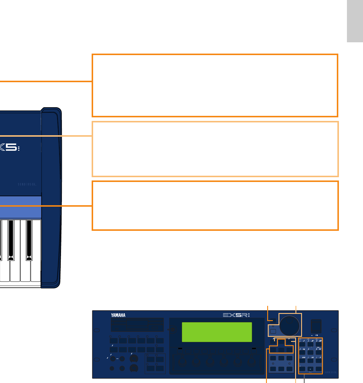
■Scene Controller Assign
Sets the controller for Scene Control. You can select
Modulation Wheel 2 or Foot Controller.
❏ Settings: MW2 (Modulation Wheel 2), FC (Foot
Controller)
For more information on Scene Control, see page 57.
■Ribbon Controller Mode
Sets whether the Ribbon Controller value returns to
a center value when you release your finger from the
Ribbon Controller (reset), or the value is retained at
the value that your finger held before releasing
(hold).
❏ Settings: hold, reset
This parameter is not available with EX5R.
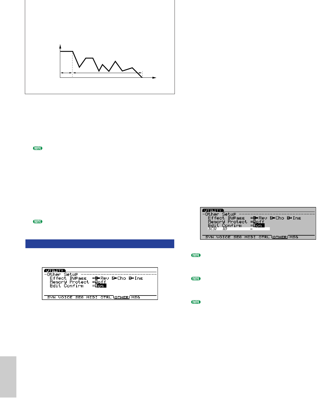
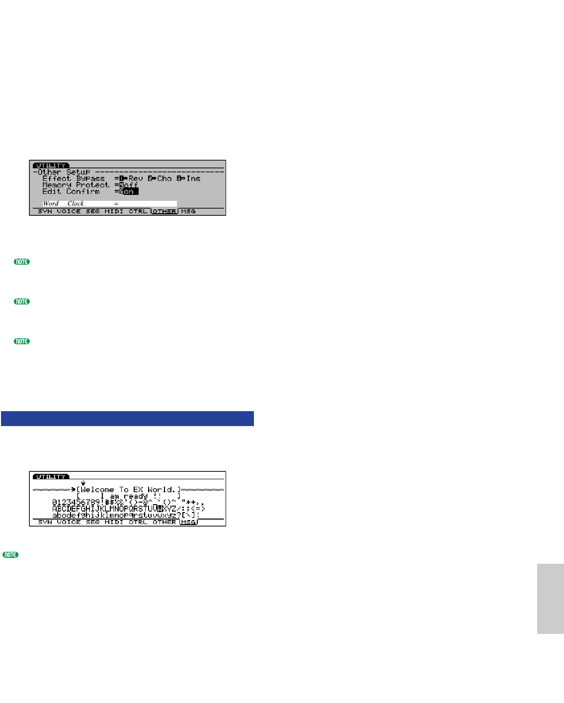
[F6]: OTHER (Other Setup)
The “Other” Setup allows you to make misllaneous
settings that are applied to the entire system.
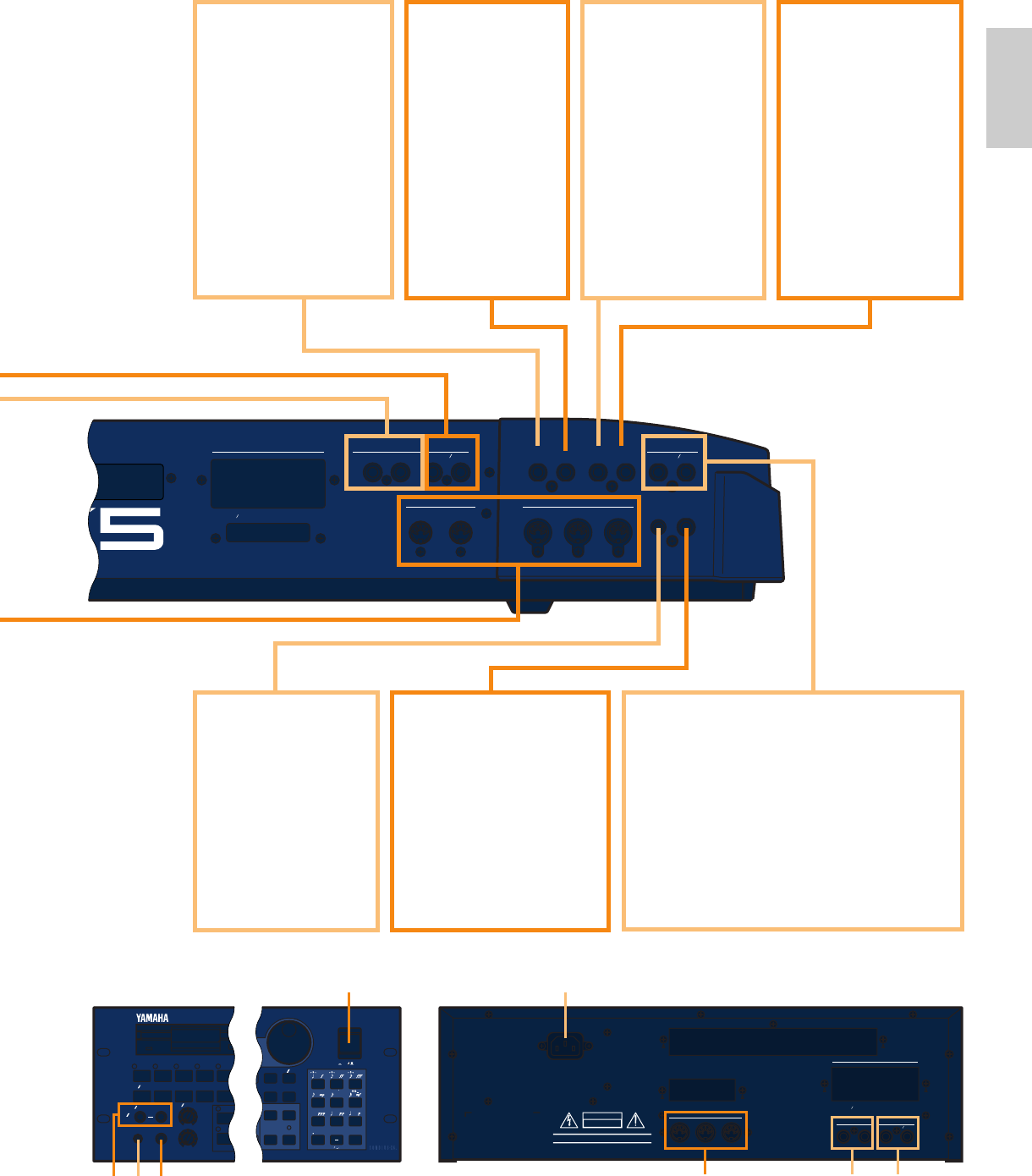
■Effect Bypass
Selects the type of effect that is by-passed (the effect
is not applied) when [EF BYPASS] ([BYPASS] on the
EX5R) is pressed on the front panel.
❏ Settings:Rev (Reverb), Cho (Chorus), Ins (Insertion) each
can be set to: ¨(Off: effect is applied), ■ (On:
effect is by-passed)
0
AB
127
Breath
Control
Time
■Memory Protect
Sets whether or not the current user Voice,
Performance, and Pattern data are protected. When
set to “on,” it is not possible to store data. This
setting is used on a temporary basis when you don’t
want to lose user data.
❏ Settings: on, off
■Edit Confirm
Sets whether or not the “Are you sure?”
confirmation message will be displayed when you
execute a Job or store data. You may want to skip the
confirmation when you are accustomed to the EX
operations. When set to “on,” the message will be
displayed, and when set to “off,” the message will
not be displayed.
❏ Settings: on, off
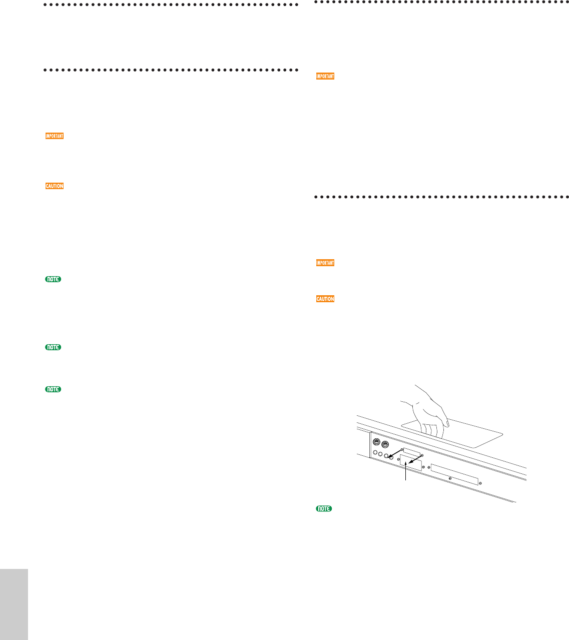
■ SCSI ID
Sets the SCSI ID number for the EX. The EX’s SCSI
ID number is set to “2” when shipped from the
factory. When connecting the EX to a SCSI device
with the same SCSI ID number, it is necessary to
change one of the devices’ ID number.
This “SCSI ID” parameter is not displayed or selected
unless you install an optional ASIB1 SCSI Interface
board.
To connect an external SCSI device to the EX, it is first
necessary to install the separately sold ASIBI (SCSI
board).
When you change the SCSI ID number, it is necessary
for you to turn the power off and back to on again, to
make the change effective.
❏ Settings: 0~7
Utility/E/qx 5/21/98 11:55 AM Page 276
■Word Clock
Sets whether the EX is used as the Word Clock
master or as a slave. “Word Clock” means
synchronization of the audio signal that passes
through digital devices. It is necessary to use Word
Clock when one or more digital audio devices are
connected for playback or recording.
When the EX is used as a master, the Word clock is
set at a sampling rate of 44.1kHz. When the EX is
used as a slave, the Word Clock automatically
changes to the clock received at WORD CLOCK IN
(WORD CLOCK IN: separately sold EXDGO1 jack).
❏ Settings: internal (EX = master), external (EX = slave)
This “Word Clock” parameter is not displayed or
selected unless you install an optional EXDGO1 Digital
Output Board.
For the EX to output a digital signal, it is necessary to
install the separately sold EXDGO1 (Digital Output
Board).
When receiving word clock from an external audio
device, you will need to connect the EXDGO1 (Word
Clock In [BNC] jack) and the external audio device. In
this case, use the BNC connector/coaxial cable with the
impedance characteristics, 75Ω.
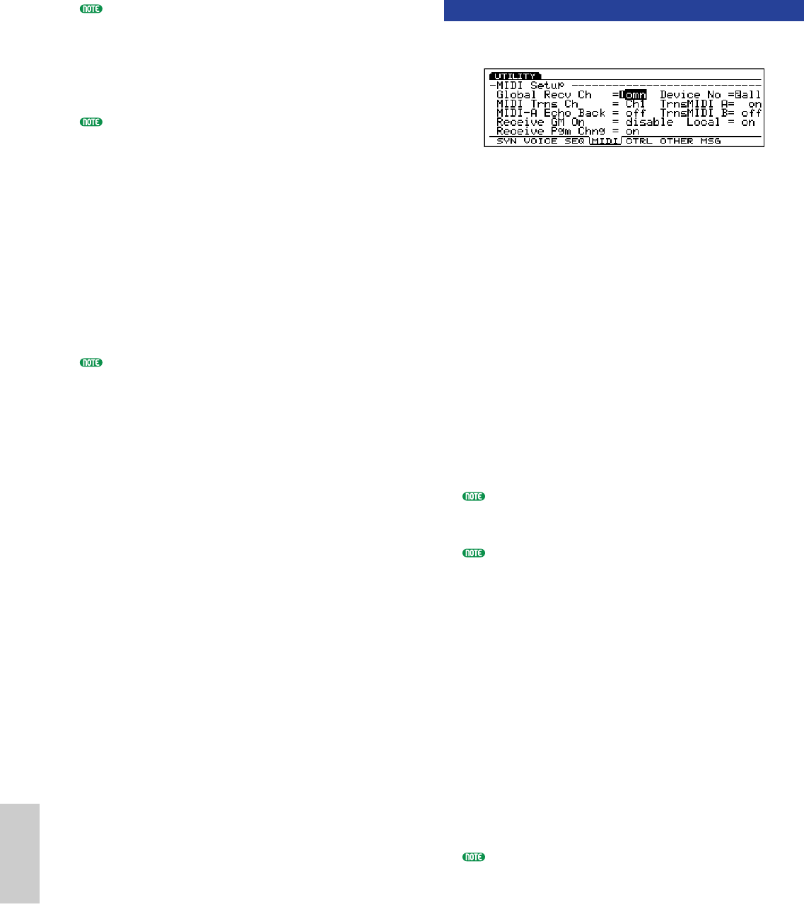
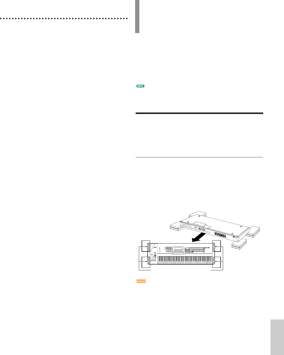
[F7]: MSG (Greeting Message)
Sets the message that will be momentarily displayed in
the screen when the power is turned on. The message
can be up to a maximum of 20 characters.
For more information or how to input characters, see page
79.
277
Utility Mode
Utility/E/qx 5/21/98 11:55 AM Page 277
Appendix
278
Appendix
Precautions When Installing
the Optional Boards
Remember the following precautions and install the
boards properly.
•To avoid using the wrong parts and making mistakes
during installation, follow the steps as written.
•Before starting installation, be sure that you have a
Phillips screwdriver at hand.
•All necessary screws are provided with the optional
boards or are installed on the EX5/5R/7. Therefore
do not use any screws other than what are installed
on the EX5/5R/7 or come with the optional board.
Screws that are not the correct size may cause
damage or result in a malfunction.
•Be careful not to misplace any of the screws since all
of them are used.
•The screw should secure the board so it is
completely stable and does not move in any way.
•Handle the boards with care. Dropping or subjecting
the board to any kind of shock may cause damage or
result in a malfunction.
•When moving a cable, be careful not to let it catch
on the circuit board. Forcing the cable in anyway
may cut the cable, cause damage, or result in a
malfunction.
•Do not touch the exposed metal parts in the circuit
board. Touching these parts may result in a faulty
contact.
•When connecting cables or directly inserting a board
(DRAM SIMM for example), make sure that you
check that they are connected or inserted properly.
Improperly inserted cables and boards may cause
faulty contacts and an electrical short circuit which
may cause damage or result in a malfunction.
•Be careful of static electricity. There are times when
static electricity affects the IC chips on the main
board. Before you lift the optional board, to reduce
the possibility of static electricity, touch the metal
parts other than the painted area or a ground wire
on the devices that are grounded.
A variety of optional boards/memories sold separately
let you expand the functions of your EX5/5R/7. The
following five types of boards/memories can be used
with the EX5/5R/7.
●EXIDO1 (Individual Output Board)
The EXIDO1 increases the number of assignable audio
output jacks. The EX5/5R comes with four outputs,
L/MONO, R, and Individual Output 1, 2. Installing the
board which has four Individual Outputs 3~6 brings
the total of outputs to eight. The EX7 with L/MONO
and R stereo outputs along with the Individual Out
1~4 is capable of a total of six outputs.
●EXDGO1 (Digital Output Board)
The EXDGO1 after installation provides an AES/EBU
digital out jack and a Word Clock In jack.
The EXDGO1 and EXIDO1, two boards can not be
installed at the same time.
●ASIB1 (SCSI Interface Board)
A SCSI connector can be installed in the EX5/5R/7.
This lets you connect external SCSI devices, such as
hard disk drives, ZIP, JAZZ disk drives and CD-ROM
drives. External SCSI device operations are
accomplished in the Disk mode.
●EXFLM1 (Flash Memory Board)
When the power is turned off, all the data in RAM is
lost. However, Flash memory data is not volatile and
remains recorded. When Flash memory is installed, just
like ROM, the data can be used as soon as the system is
turned on. In the EX5/5R/7, Flash memory (4MB x
2=8MB) can be used to store sample data. Also the
data can be overwritten whenever you like.
Take note that the EXFLM1 should always be used in
pairs.
●DRAM SIMM
DRAM SIMM (Single In-line Memory Module) can be
used as RAM for recording sample data. You need to
use 72-pin DRAM SIMMs (4, 8, 16, 32MB) in pairs. It
is possible to increase the 1MB of internal memory, a
maximum of 64MB to a total of 65MB. (However,
because the data is volatile, it is necessary to backup
data to floppy disk or an external SCSI device.)
Take note that DRAM SIMMs with the same memory
capacity should always be used in pairs.
Optional Boards/Memories
Option/E/qx 5/21/98 11:58 AM Page 278
279
Appendix
Precautions When
Purchasing DRAM SIMMs
Some of the commercially available DRAM SIMMs
may not work on the EX5/5R/7. Yamaha cannot
be held responsible for malfunction of DRAM
SIMMs. BEFORE purchasing, please consult
(which to buy) the shop where you bought
EX5/5R/7 or your nearest Yamaha (or the
authorized distributor) listed at the end of this
manual.
Important Notices About DRAM SIMM
Type/Configuration.
•You need to use 72-pin DRAM SIMMs (4, 8, 16,
32MB) with the same memory capacity in pairs.
•You need to use DRAM SIMMs with access time of
70ns or less.
•Both types, parity and non-parity types can be used.
It is also possible to use the EDO type.
•DRAM SIMMs corresponding to ECC cannot be
used.
•For the EX5/7 (keyboard), you need to use DRAM
SIMM with its height less than 32mm.
•Yamaha recommends to select the DRAM SIMMs
that meet the standard specification for internal
configuration set by the JEDEC*. However, be aware
that the recommendation does NOT always assure
that the DRAM SIMMs operate with the EX5/5R/7.
*The JEDEC (Joint Electron Device Engineering Council) is a
technical electronic device association. This association sets
regulations for standard terminal configuration in electronic
devices.
How to Install the
Optional Board/
Memory (EX5/7)
The installation method is different depending on the
instrument types, EX5/7 keyboards and EIA sized
module, EX5R. Both methods are explained separately
on the following pages. Read the explanation carefully
for the instrument that you will use. The board and
cable to be used are described in the beginning of each
installation procedure.
For information on how to handle the EX5R, go to page
285.
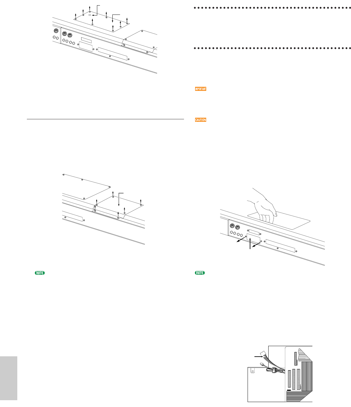
Preparation
On the EX5/7, there are two types of covers, one is for
optional boards and the other is for memories. Remove
the appropriate cover according to the board/memory
that you will install.
How to Remove the Optional Board
Cover (EXIDO1, EXDGO1, ASIB1)
1Turn the EX power off, and disconnect the power
cord.
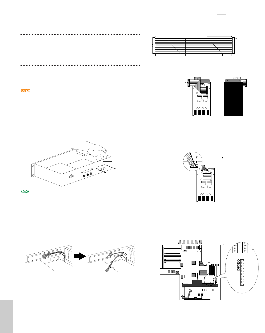
2Turn over the keyboard so you can have direct
access to the underside. To protect the Knobs or
Wheels, place the keyboard so the four corners are
supported by something that provides sufficient
support like magazines or cushions.
Be careful not to drop or bump the keyboard and
make sure that it is well balanced before proceeding.
Place the supports at all four corners,
without touching the Knobs and the
Wheels.
View of the keyboard
from the bottom.
Option/E/qx 5/21/98 11:58 AM Page 279
280
Appendix
3Move to a position facing the rear panel of the
EX5/7, and remove the screws from the optional
board cover on the left side with a Phillips
screwdriver (eight screws). Do not remove the large
screw shown in the illustration.
Remove the optional board cover and you will see
the installation connectors.
How to Remove the Memory Cover
(EXFLM1, DRAM SIMM)
Steps 1and 2are the same as those explained in
removing the optional board cover.
3Move to a position facing the rear panel of the
EX5/7, and remove the screws from the memory
cover on the right side with a Phillips screwdriver
(six screws).
Remove the memory cover and you will see the
installation sockets.
For information on how to handle the EX5R, see page
285.
Memory cover
Do not remove this screw.
Optional board cover
Memory cover
Rear panel
How to Install the
EXIDO1
in the EX5/7
Necessary Items
•EXIDO1 (Individual Output Board)x 1
•Flat cablex 1 (included in the EXIDO1 package)
Installation
You can install the EXIDO1 after removing the
optional board cover. For more information on
removing the optional board cover, see How to Remove
the Optional Board Cover.
If the ASIB1 (SCSI Interface Board) is already
installed, it must first be removed before proceeding.
If you want to install the two boards simultaneously,
first install the EXIDO1.
When installing the optional board (from when you
remove the cover to when the cover is replaced
securely) all operations must be done with the power
cord disconnected.
1Remove the two screws from the EXIDO1/EXDGO1
opening cover (hold the cover from inside the EX5/7
as you remove the cover). The two screws will be
used again when securing the EXIDO1. Be careful
not to lose them.
After you take off the cover, do not leave it inside the
EX5/7 and put it in a safe place.
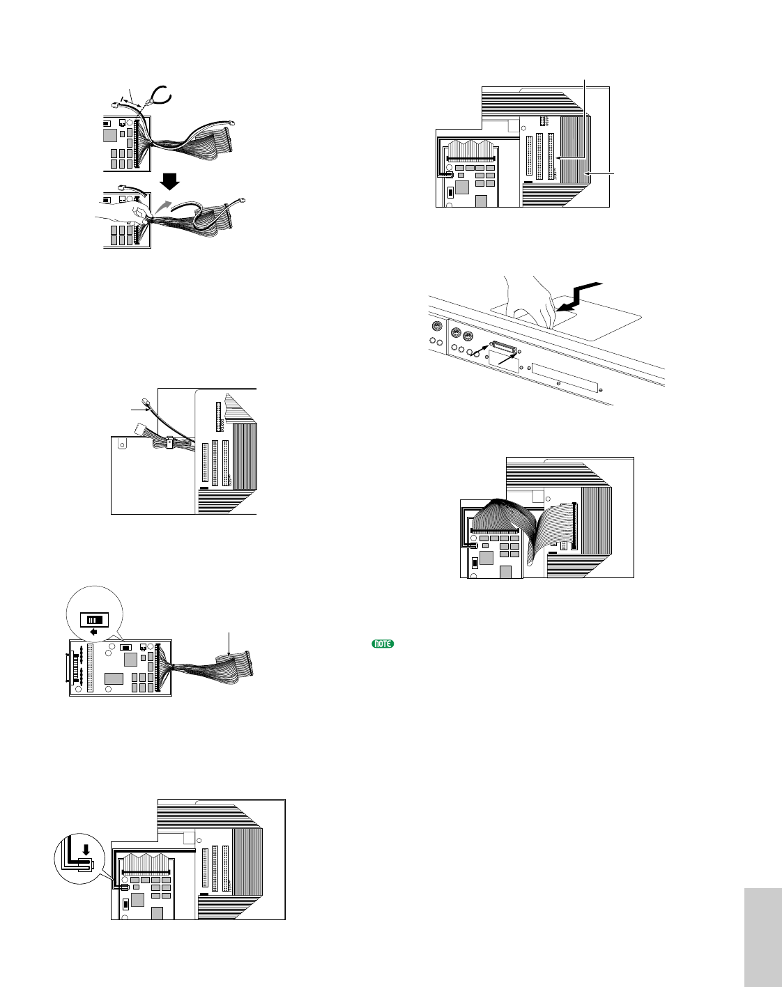
2Remove the EXIDO1/EXDGO1 power cable (1 red
and 4 white, 5 pin cable) from the hook-shaped
bundle tie in the EX5/7. Make sure not to catch the
cable on any other cables or the circuit board while
removing it from the hook-shaped bundle tie and set
it aside. Place the remaining cable back into the
bundle tie.
Power cable
Opening cover
Option/E/qx 5/21/98 11:58 AM Page 280
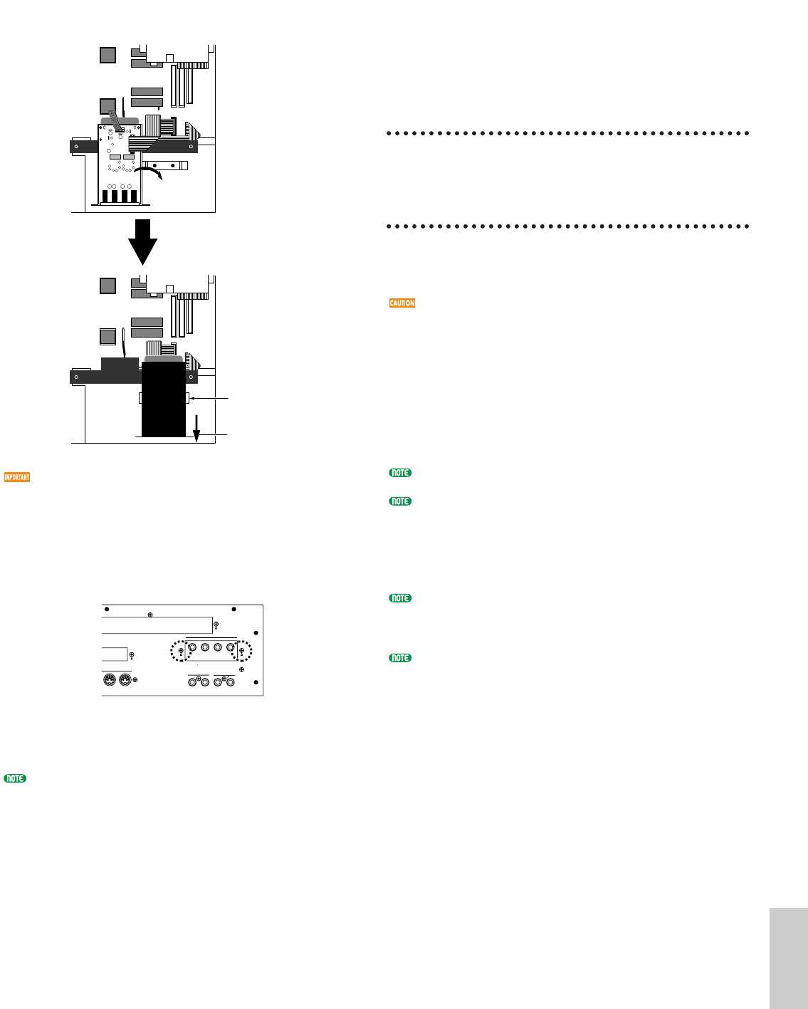
3Support the EXIDO1 with your hand and use the
two screws removed in step 1to attach the board to
the rear panel of the EX5/7.
4Use the two screws that are attached to the EXIDO1
to attach the board to the EX5/7 metal fitting.
5Connect the EXIDO1/EXDGO1 power cable that
was set aside in step 2to the EXIDO1 connector. Be
careful not to connect the connector in the wrong
direction.
6As shown in the diagram, bend the flat cable to the
specified dimensions.
80mm
Indicates that the cable
should be folded upwards
at this line.
Indicates that the cable
should be folded downwards
at this line.
5mm
50mm35mm
Blue marking
Connect the connector
(Make sure that the connector
is facing the correct direction)
Line up the red cable with this mark .
Fix the board with the two screws.
FDD cable
EXIDO1
7Check the location of the DGO/IDO connector in
the EX5/7 and connect the EXIDO1 and EX5/7 with
the flat cable. The DGO/IDO connector is hidden
under the FDD cable. “DGO/IDO” is printed on the
panel.
When you lift up the FDD cable to connect the flat cable
to the DGO/IDO connector, the FDD cable may
inadvertently be pulled out of the connector. Make sure
that the FDD cable is securely connected after connecting
the optional board.
8Replace the optional board cover by following the
steps for removal in the opposite order.
The Individual Output jacks to be added are numbered as
follows.
• EX5: INDIVIDUAL OUTPUT 3~6
• EX7: INDIVIDUAL OUTPUT 1~4
For information on Individual Output settings, see page
19.
DGO/IDO connector
FDD cable
Before connectionAfter connection
Connector on
the EXIDO1
281
Appendix
Option/E/qx 5/21/98 11:58 AM Page 281
282
Appendix
How to Install the
EXDGO1 in the EX5/7
Necessary Items
•EXDGO1 (Digital Output Board)x 1
•Flat cablex 1 (included in the EXDGO1 package)
Installation
You can install the EXDGO1 after removing the
optional board cover. For more information on
removing the optional board cover, see How to Remove
the Optional Board Cover.
If the ASIB1 (SCSI Interface Board) is already
installed, it must first be removed before proceeding.
If you want to install the two boards simultaneously,
first install the EXDGO1.
When installing the optional board (from when you
remove the cover to when the cover is replaced
securely) all operations must be done with the power
cord disconnected.
The procedure for installing the EXDGO1 is the same
as for the EXIDO1. Refer to How to Install the
EXIDO1 in the EX5/7.
For information on Word Clock settings, see Utility mode
(page 277).
When the EXDGO1 is properly installed, L and R
signals will be output digitally.
When connecting the EXDGO1 (Digital Output AES/EBU
[XLR] jack) and an external audio device, use the XLR
cable with the impedance characteristics, 110Ω
When receiving word clock from an external audio device,
you are required to connect the EXDGO1 (Word Clock In
[BNC] jack) and the external audio device. In this case, use
the BNC connector/coaxial cable with the impedance
characteristics, 75Ω
How to Install the ASIB1
in the EX5/7
Necessary Items
•ASIB1 (SCSI Interface Board)x 1
•SCSI cable (Flat cable 50P; length: 280mm)x 1
(included in the ASIB1 package)
•Cutting pliers or scissors (to cut a cable)
When you open the package of the ASIB1 board, you
will find two SCSI cables connected to the ASIB1,
and two (2-pin) power cables, one is plugged to the
ASIB1 and the other is left unplugged. To install the
ASIB1 into the EX, only the short (280mm long)
SCSI cable is used. First, it is necessary to remove
the long (480mm long) SCSI cable and 2-pin power
cable from the ASIB1 board.
Installation
You can install the ASIB1 after removing the optional
board cover. For more information on removing the
optional board cover, see How to Remove the Optional
Board Cover.
When two boards are installed simultaneously such as
the ASIB1 and EXIDO1 (or EXDGO1), first install the
EXIDO1 (or EXDGO1).
When installing the optional board (from when you
remove the cover to when the cover is replaced
securely) all operations must be done with the power
cord disconnected.
1Remove the two screws from the ASIB1 opening cover (hold
the cover from inside the EX5/7 as you remove the cover).
The two screws will be used again when securing the ASIB1.
Be careful not to lose them.
After you take off the cover, do not leave it inside the
EX5/7 and put it in a safe place.
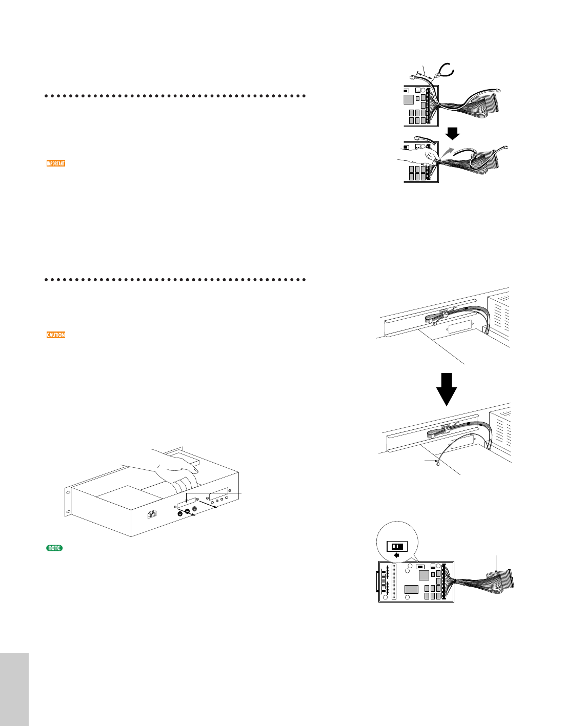
2Disconnect the long (480mm long) SCSI cable from
the connector (CN1) on the ASIB1 board.
Opening cover
Option/E/qx 5/21/98 11:58 AM Page 282
3Unplug the 2-pin power cable from the ASIB1 and
remove it from the ASIB1. To remove the 2-pin
power cable, cut the cable and then pull it out from
the hoop as shown in the illustration.
4Remove the ASIB1 power cable (1 red and 1 white, 2
pin cable) from the hook-shaped bundle tie in the
EX5/7. Make sure not to catch the cable on any
other cables or the circuit board while removing it
from the hook-shaped bundle tie and set it aside.
Place the remaining cable back into the bundle tie.
5Set the TERM switch (Terminator) to ON on the
ASIB1 board.
6Connect the ASIB1 power cable that was set aside in
step 4to the CN2 connector (next to the TERM
switch) on the ASIB1. Be careful not to connect the
connector in the wrong direction.
ON TERM OFF
ON TERM OFF
ON TERM OFF
Short (280mm long) SCSI cable
Power cable
E
RM OFF
2cm
E
RM OFF
Cut here
Pull out
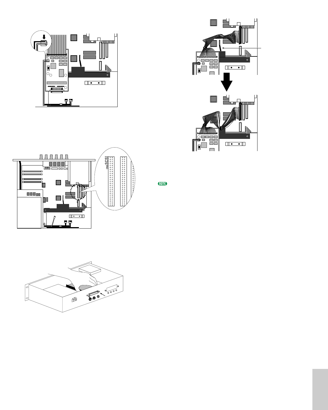
7Check the location of the SCSI connector in the
EX5/7 (shown in the illustration) and connect the
ASIB1 and the EX5/7 with the SCSI cable. “SCSI” is
printed on the panel next to the SCSI connector.
8Support the ASIB1 with your hand and use the two
screws removed in step 1to attach the board to the
rear panel of the keyboard.
9Arrange the SCSI cable so it sits in between the
ASIB1 and the panel.
)Replace the optional board cover by following the
steps for removal in the opposite order.
For information on SCSI ID settings, see the Utility mode
(page 276).
ON TERM OFF
ON TERM OFF
SCSI connector
FDD cable
283
Appendix
Option/E/qx 5/21/98 11:58 AM Page 283
284
Appendix
How to Install the EXFLM1/
DRAM SIMM in the EX5/7
Necessary Items
•EXFLM1x 2 (use only in pairs)
or
•DRAM SIMMx 2 (use only in pairs)
Make sure always use the EXFLMs in pairs, also always
use the DRAM SIMMs with the same memory capacity in
pairs.
Installation
You can install the EXFLM1 and DRAM SIMM after
removing the memory cover. For more information on
removing the memory cover, see How to Remove the
Memory Cover.
When installing the memory board (from when you
remove the cover to when the cover is replaced
securely) all operations must be done with the power
cord disconnected.
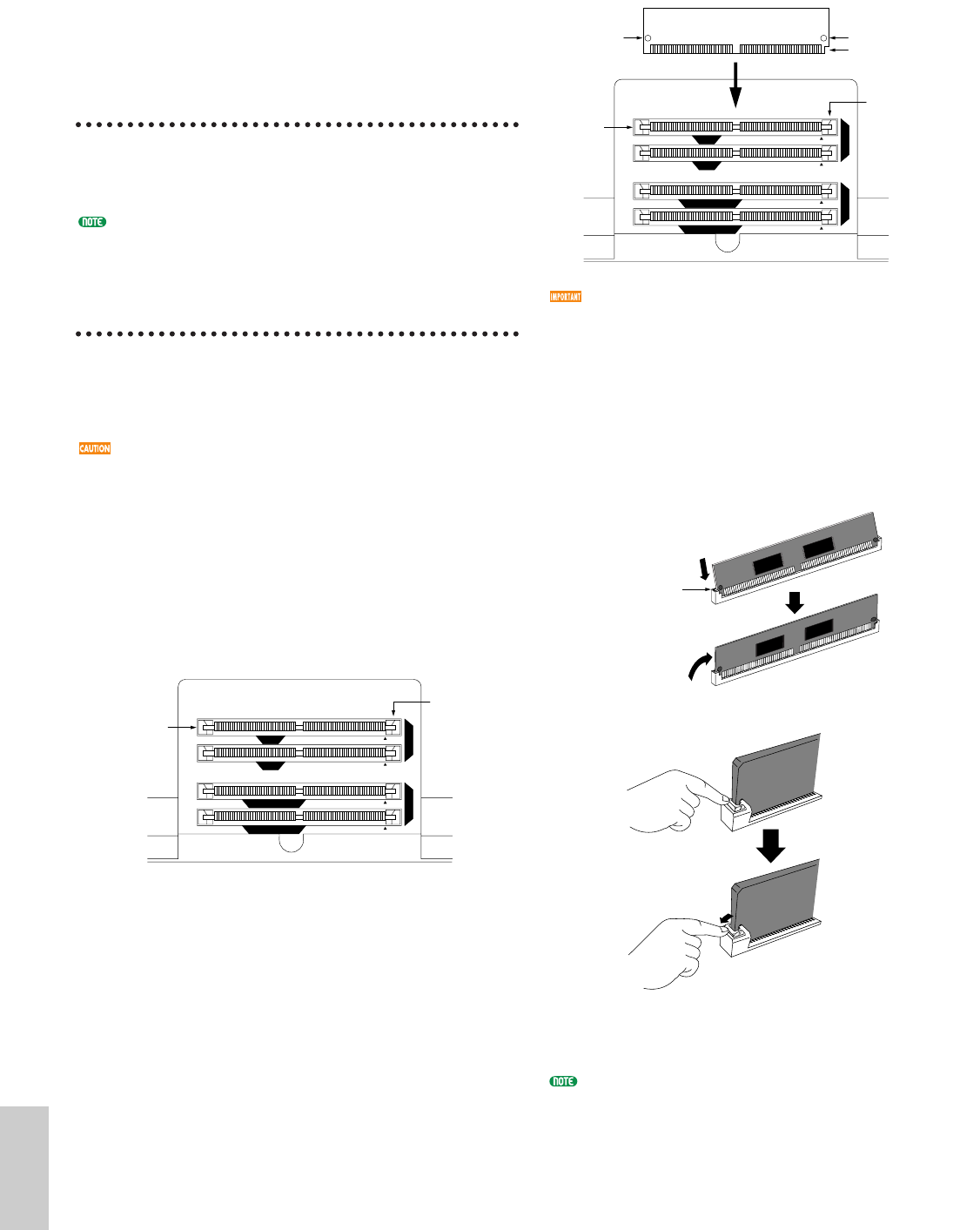
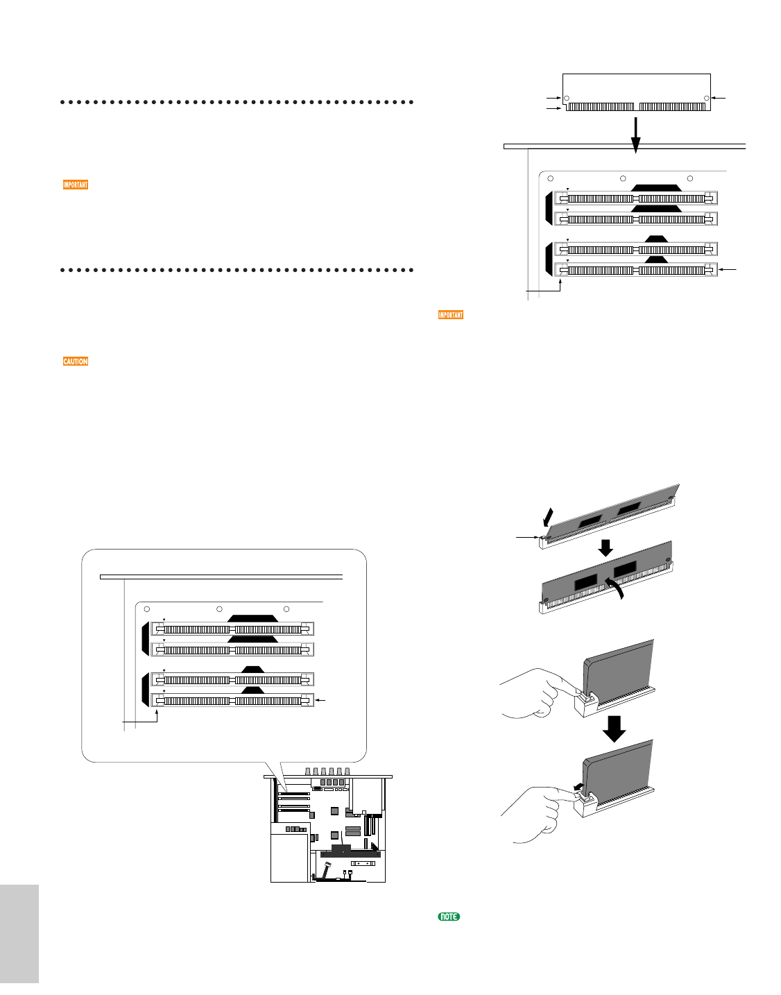
1Check the location of the memory slots. When facing
the rear panel of the EX5/7, on the back of the board
in the EX5/7, the two rows (to the right of the
sockets “EXFLM1” is printed) are the EXFLM1
sockets. The two rows (to the right of the sockets
“DRAM” is printed) before the EXFLM1 are the
DRAM SIMM sockets.
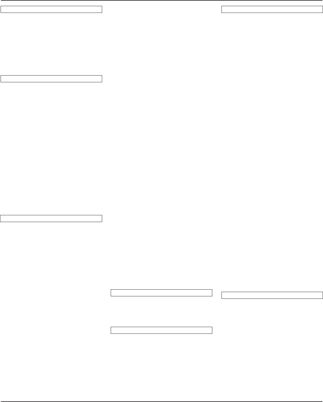
2On the EXFLM1 and the DRAM SIMM memory
there is a cut in the board next to 1PIN. Insert the
board into the socket so that 1PIN lines up with the
1PIN mark (▲) printed on the board in the EX5/7.
Hook
Hook
EXFLM1
Rear
DRAM
DRAM SIMM
DRAM SIMM
YFL
YFL
The sockets for the EXFLM1 and DRAM SIMM look
the same. Be careful not to insert the memory into the
wrong socket.
3Install the EXFLM1 or DRAM SIMM by inserting
the first board into the socket closest to you. Set the
EXFLM1 or DRAM SIMM completely into the
socket at an angle shown in the illustration. Then
push in the direction shown below so that it becomes
upright and the hook snaps into place. Repeat this
step for the second board.
4Replace the memory cover by following the steps for
removal in the opposite order.
To remove a EXFLM1 or DRAM SIMM from a socket,
hold open the two hooks on the socket (one at each end)
and push on the EXFLM1 or DRAM SIMM so that it is
released from the hooks and becomes slanting, and then
pull the EXFLM1 or DRAM SIMM out.
Insert completely into the
socket at this angle.
The hooks catch and the board
stands vertical, securely inserted.
Hook
72PIN1PIN
Hook hole
Cut that indicates 1 PIN
Hook hole
Hook
Hook
EXFLM1
Rear
DRAM
DRAM SIMM
DRAM SIMM
YFL
YFL
Option/E/qx 5/21/98 11:58 AM Page 284
How to Install the
Optional Board/
Memory(EX5R)
Preparation
On the EX5R, remove the main unit top cover for all
optional board/memory installations.
For information on how to handle the EX5/7, go to page
279.
How to Remove the EX5R Top Cover
1Turn the EX power off, and disconnect the power
cord.
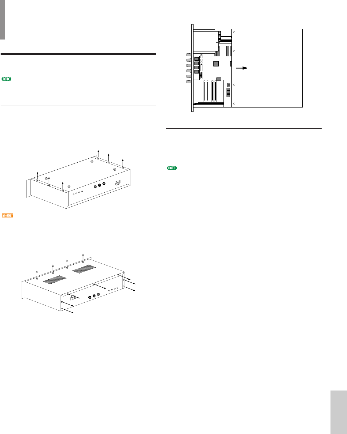
2Turn over the main unit and remove the six screws
on the left and right sides that secure the EX5R top
cover.
Do not remove the other screws.
3Return the unit to its original upright position and
remove the four screws on the top surface located at
the front of the unit and also the seven screws
located on the rear.
Top
Front
Rear
Bottom
4Remove the EX5R top cover by sliding the cover in a
backwards direction and you will see the installation
connectors/sockets.
How to Replace the EX5R Top Cover
Replace the top cover by following the steps for
removal in the opposite order (First replace the seven
rear screws, next the four top screws, and then the
bottom six screws).
For information on how to handle the EX5/7, see page
279.
FrontRear
285
Appendix
Option/E/qx 5/21/98 11:58 AM Page 285
286
Appendix
How to Install the EXIDO1
in the EX5R
Necessary Items
•EXIDO1 (Individual Output Board)x 1
•Flat cablex 1 (included in the EXIDO1 package)
Installation
You can install the EXIDO1 after removing the main
unit top cover. For more information on removing the
main unit top cover, see above.
When installing the optional board (from when you
remove the EX5R top cover to when the cover is
replaced securely) all operations must be done with
the power cord disconnected.
1Remove the two screws from the EXIDO1/EXDGO1
opening cover (hold the cover from inside the EX5R
as you remove the cover). The two screws will be
used again when securing the EXIDO1. Be careful
not to lose them.
After you take off the cover, do not leave it inside the
EX5R and put it in a safe place.
2Remove the EXIDO1/EXDGO1 power cable (1 red
and 4 white, 5 pin cable) from the hook-shaped
bundle tie in the EX5R. Make sure not to catch the
cable on any other cables or the circuit board while
removing it from the hook-shaped bundle tie and set
it aside. Place the remaining cable back into the
bundle tie.
Power cable
Opening cover
3As shown in the diagram, bend the flat cable to the
specified dimensions.
4Connect the flat cable to the EXIDO1.
5Connect the EXIDO1/EXDGO1 power cable that
was set aside in step 2to the EXIDO1 connector. Be
careful not to connect the connector in the wrong
direction.
6Check the location of the DGO/IDO connector in
the EX5R and connect the EXIDO1 and the EX5R
with the flat cable. When facing the rear panel, the
DGO/IDO connector is on the right side as shown in
the illustration. “DGO/IDO” is printed on the panel.
DGO/IDO
Rear
Line up the red cable
with the mark .
Cable is connected.(Rear)
Make sure that
the connector is
facing the correct
direction.
20mm10mm50mm
20mm
Blue marking
Indicates that the cable
should be folded upwards
at this line.
Indicates that the cable
should be folded downwards
at this line.
50mm
Option/E/qx 5/21/98 11:58 AM Page 286
7Turn over the EXIDO1 and place face down into the
support arms.
The EXIDO1 and the EXDGO is installed in the EX5R
upside down (with the board facing down). If
installed underside down, the output jack numbers
will not match the Individual Out settings.
8Slide the EXIDO1 towards the rear panel of the
EX5R and use the two screws removed in step 1to
attach the board to the rear panel.
9Replace the EX5R top cover. See How to Replace the
EX5R Top Cover on page 285.
For information on Individual Output settings, see page
19.
MIDI
OUTIN
INDIVIDUAL OUTPUT
6543
DIGITAL OUTPUT
WORD CLOCK IN
AES EBU
INDIVIDUAL OUTPUT
21
OUTPUT
R
LMONO
Rear
Slide the board
in this direction.
Support arms
Turn over
the board.
Rear
How to Install the
EXDGO1(Digital Output Board)
in the EX5R
Necessary Items
•EXDGO1 (Digital Output Board)x 1
•Flat cablex 1 (included in the EXDGO1 package)
Installation
You can install the EXDGO1 after removing the EX5R
top cover. For more information on removing the EX5R
top cover, see How to Remove the EX5R Top Cover.
When installing the optional board (from when you
remove the top cover to when the top cover is replaced
securely) all operations must be done with the power
cord disconnected.
The procedure for installing the EXDGO1 is the same
as for the EXIDO1. See How to Install the EXIDO1 in
the EX5R.
Only the points that are different from the EXIDO1
will be explained.
Same as the EXIDO1, the EXDGO1 is installed face down.
For information on Word Clock settings, see Utility mode
(page 277).
When the EXDGO1 is properly installed, L and R
signals will be output digitally.
When connecting the EXDGO1 (Digital Output AES/EBU
[XLR] jack) and an external audio device, use the XLR
cable with the impedance characteristics, 110Ω
When receiving word clock from an external audio device,
you are required to connect the EXDGO1 (Word Clock In
[BNC] jack) and the external audio device. In this case, use
the BNC connector/coaxial cable with the impedance
characteristics, 75Ω
287
Appendix
Option/E/qx 5/21/98 11:58 AM Page 287
288
Appendix
How to Install the ASIB1
(SCSI Interface Board)in the
EX5R
Necessary Items
•ASIB1 (SCSI Interface Board)x 1
•SCSI cable (Flat cable 50P; length: 280mm)x 1
(included in the ASIB1 package)
•Cutting pliers or scissors (to cut a cable)
When you open the package of the ASIB1 board, you
will find two SCSI cables connected to the ASIB1,
and two (2-pin) power cables, one is plugged to the
ASIB1 and the other is left unplugged. To install the
ASIB1 into the EX, only the short (280mm long)
SCSI cable is used. First, it is necessary to remove
the long (480mm long) SCSI cable and 2-pin power
cable from the ASIB1 board.
Installation
You can install the ASIB1 after removing the EX5R top
cover. For more information on removing the EX5R top
cover, see How to Remove the EX5R Top Cover.
When installing the optional board (from when you
remove the top cover to when the top cover is replaced
securely) all operations must be done with the power
cord disconnected.
1Remove the two screws from the ASIB1 opening
cover (hold the cover from inside the EX5R as you
remove the cover). The two screws will be used
again when securing the ASIB1. Be careful not to
lose them.
After you take off the cover, do not leave it inside the
EX5R and put it in a safe place.
2Disconnect the long (480mm long) SCSI cable from
the connector (CN1) on the ASIB1 board.
Opening cover
3Unplug the 2-pin power cable from the ASIB1 and
remove it from the ASIB1. To remove the 2-pin
power cable, cut the cable and then pull it out from
the hoop as shown in the illustration.
4Remove the ASIB1 power cable (1 red and 1 white, 2
pin cable) from the hook-shaped bundle tie in the
EX5R. Make sure not to catch the cable on any other
cables or the circuit board while removing it from
the hook-shaped bundle tie and set it aside. Place the
remaining cable back into the bundle tie.
5Set the TERM switch (Terminator) to ON on the
ASIB1 board.
ON TERM OFF
ON TERM OFF
Short (280mm long) SCSI cable
Power cable
E
RM OFF
2cm
E
RM OFF
Cut here
Pull out
Option/E/qx 5/21/98 11:58 AM Page 288
289
6Connect the ASIB1 power cable that was set aside in
step 4to the CN2 connector (next to the TERM
switch) on the ASIB1. Be careful not to connect the
connector in the wrong direction.
7Check the location of the SCSI connector in the
EX5R (shown in the illustration), and connect the
ASIB1 and the EX5R with the SCSI cable. “SCSI” is
printed on the panel next to the SCSI connector.
8Support the ASB1 with your hand and use the two
screws removed in step 1to attach the board to the
rear panel of the EX5R.
ON TERM OFF
9Use the bundle tie next to the ASIB1 to bundle the
cables together.
)Replace the EX5R top cover. See How to Replace the
EX5R Top Cover.
For information on SCSI ID settings, see the Utility mode
(page 276).
ON TERM OFF
ON TERM OFF
Bundle tie
Appendix
Option/E/qx 5/21/98 11:58 AM Page 289
290
HowtoInstalltheEXFLM1/
DRAM SIMM in the EX5R
Necessary Items
•EXFLM1x 2 (use only in pairs)
or
•DRAM SIMMx 2 (use only in pairs)
Make sure always use the EXFLMs in pairs, also always
use the DRAM SIMMs with the same memory capacity in
pairs.
Installation
You can install the EXFLM1 and DRAM SIMM after
removing the EX5R top cover. For more information on
removing the EX5R top cover, see How to Remove the
EX5R Top Cover.
When installing the memory board (from when you
remove the top cover to when the top cover is replaced
securely) all operations must be done with the power
cord disconnected.
1Check the location of the memory slots. When facing
the rear panel of the EX5R, the DRAM SIMM two
rows (to the left of the sockets DRAM is printed) are
on the back of the board on the far left side of the
EX5R. The two rows in front of the DRAM SIMM
rows (to the left of the sockets EXFLM1 is printed)
are the EXFLM1 sockets.
DGO/IDO
Hook
Hook
Front
EXFLM1DRAM
DRAM SIMM
DRAM SIMM
YFL
YFL
2On the EXFLM1 and the DRAM SIMM memory
there is a cut in the board next to 1PIN. Insert the
board into the socket so that 1PIN lines up with the
1PIN mark (▲) printed on the board in the EX5R.
The sockets for the EXFLM1 and DRAM SIMM look
the same. Be careful not insert the memory into the
wrong socket.
3Install the EXFLM1 or DRAM SIMM by inserting
the first board in the socket farthest from you. Set
the EXFLM1 or DRAM SIMM into the socket at an
angle shown in the illustration. Then push in the
direction shown below so that it becomes upright
and the hook snaps into place. Repeat this step for
the second board.
4Replace the EX5R top cover. See How to Replace the
EX5R Top Cover.
To remove a EXFLM1 or DRAM SIMM from a socket,
hold open the two hooks on the socket (one at each end)
and push on the EXFLM1 or DRAM SIMM so that it is
released from the hooks and becomes slanting, and then
pull the EXFLM1 or DRAM SIMM out.
Insert completely into the
socket at this angle.
The hooks catch and the board
stands vertical, securely inserted.
Hook
1PIN72PIN
Hook hole
Cut that indicates 1PIN
Hook hole
Hook
Hook
Front
EXFLM1DRAM
DRAM SIMM
DRAM SIMM
YFL
YFL
Appendix
Option/E/qx 5/21/98 11:58 AM Page 290
Appendix
291
Troubleshooting
The following table provides troubleshooting hints and page references for some common
problems. Most problems may be simply the result of incorrect settings. Before calling for
professional service, refer to the troubleshooting advice below to see if you can find and
correct the cause of the problem.
No sound.
● Is the volume set appropriately? (P. 9)
● (On EX5/7) When the Foot Controller is connected to the FOOT VOLUME jack, is the Foot
Volume pressed down? (P. 17)
● Is the Volume parameter in PARAM, COM menu (Voice Edit) set appropriately? (P. 77)
● Is the Level parameter in PARAM, AMP menu (Voice Edit) set appropriately? (P. 96)
● Is the Level parameter in MIX, OSC menu (Voice Edit) set appropriately? (P. 81)
● Is the note range/velocity (note) range in ZONE, OSC menu (Voice Edit) set appropriately? (P. 82)
● Isn't each element muted? (P. 77)
● Filters set for each element may inadvertently cut almost all the sound? (P. 86)
● (AN elements) Is the PulseWidth parameter in VCO, OSC menu (Voice Edit) set appropriately? (P. 116)
● Are the effect settings appropriate? (P. 105)
● Are the MIDI receive channels set appropriately? (P. 165, 271)
● Is the audio equipment connected appropriately? (P. 18)
● Isn't Local set to off? (P. 275)
● Are the settings, Velocity Sensitivity, Note Limit and Velocity Limit appropriate? (P. 166, 82)
● (When playing back a song using the internal sequencer or an external MIDI device,) are the
volume and expression settings for the song data appropriate?
● (When playing performances using the internal sequencer or an external MIDI device,) Are the
MIDI settings, transmit channels of each sequencer track and receive channels of each part of
the performance, set appropriately? (P. 171)
● (Performance) Is the volume of each part set enough? (P. 167)
● (Performance) Is the Output Select of each part set appropriately? (P. 167)
Appen./E/qx 5/21/98 11:56 AM Page 291
292
No arpeggiator sound.
● Is each part of the arpeggiator muted? (P. 239)
● Are the settings, Velocity Sensitivity and Velocity Limit appropriate? (P. 166)
● Is the note range for the arpeggiator set appropriately? (P. 161)
● (User arpeggio) Are the sequence data properly recorded? (P. 245)
● (Performance mode) Are the Layer Switch and Arpeggio Switch for the part(s) turned on? (P. 171)
Distorted sounds.
● Are the effect settings appropriate? (P. 105)
● Is the volume level set too loud? (P. 79, 96)
● (AN elements) Are the FM parameter and Sync parameter in ALG, OSC menu (Voice Edit) set
too high? (P. 114)
● (AN elements) Is the Feedback Level in MIX, AMP menu (Voice Edit) set too high? (P. 120)
Small sounds.
● Is the MIDI volume or MIDI expression set too low?
● Are the Velocity Sens/Offset in the Voice Mode Setup (Utility mode) set too low? (P. 271)
● Is the cutoff frequency of the filters set too high/low? (P. 110, 118)
Wrong pitch.
● Is the Master Tune in the Synthesizer Setup (Utility mode) set appropriately? (P. 270)
● Are the pitch related parameters in PARAM, PITCH menu (Voice Edit) set appropriately? (P. 83)
● Is the appropriate tuning system selected from Micro Tuning parameter in SCALE, PITCH menu
(Voice Edit)? (P. 84)
● (AN elements) Is the Sync Pitch parameter in ALG, OSC menu (Voice Edit) set appropriately? (P. 114)
● Is the Pitch Modulation Depth in LFO1, LFO menu (Voice Edit) set too high? (P. 102)
● (Performance) Is the Note Shift for each part in LYR (Layer) set to a value other than 0? (P. 171)
● (Performance) Is the Detune for each part in MIX set to a value other than 0? (P. 171)
Sound is choppy and interrupted.
● Do the total number of notes required to the data exceed the maximum polyphony? (P. 78)
● (User arpeggio) Are the velocity and play effects for the arpeggio set appropriately? (P. 239)
Appendix
Appen./E/qx 5/21/98 11:56 AM Page 292
293
Only one note sounds at a time.
● Is the “mono” selected from Mono/Poly parameter in PARAM, COM menu (Voice Edit)? (P. 79)
● (Performance) Is the "mono" selected from Mono/Poly parameter of each part? (P. 165)
No effect applied.
● Is [EF BYPASS] key turned off? (P. 10)
● Is the InsEF Elem Sw in TYPE, EFCT menu turned on? Also, is the effect type other than 00
(thru) selected for each effect type in TYPE, EFCT menu?(P. 105)
● (Performance) Is the InsEF Elem Sw for each part turned off? Also, is the effect type other than
00 (thru) selected for each effect type in EFCT, COM menu?(P. 165)
Appendix
Appen./E/qx 5/21/98 11:56 AM Page 293
LCD Messages
294
Appendix
Failed to process the MIDI data because too much data is received at one time.
Information
Remaining memory of the internal sequencer has been consumed.
An error occurred when receiving MIDI data.
An error occurred when receiving bulk data.
The internal backup battery has been consumed. Replace the battery.
Sequence data (bulk) has been received, but it contains no data.
Wrong MIDI data was received.
Can't select a mode. Turn the Keymap/Arpeggiator off.
Can't select a mode. Turn the Keymap off.
MIDI bulk data has been received.
EX is receiving MIDI bulk data.
Can't edit the data because it is a preset data.
SCSI ID is not properly set.
There is no more memory available on the disk.
Can't find the specified type of file.
The disk is faulty.
The disk has not been inserted.
The disk has not been properly formatted.
The disk is write protected.
The format type of the disk is wrong.
The file with the same name already exists.
The file data is faulty.
Can't make more than two directory levels.
The file format type is not for EX.
The timebase of the designated SMF file is wrong.
VL controller set cannot be created since the controller sets are full.
It is not possible to execute the undo operation.
Bulk data cannot be transmitted/received since the device number is off.
Bulk data cannot be transmitted/received since the device numbers don't match.
EX is transmitting MIDI bulk data.
Wave Editor has been canceled.
EX has received sample data from Wave Editor.
EX is receiving sample data from Wave Editor.
EX is transmitting sample data to Wave Editor.
The number of wave layers are full.
There is no more memory available on the Flash Memory Board.
There is no more memory available on the sample (D)RAM.
The number of waves are full.
The number of samples are full.
DSP has been occupied by another use.
The number of elements are full.
To mute the elements, press an appropriate number key while holding [SHIFT] key.
To store the scene, press [SCENE] key while holding [STORE] key.
Displayed when EX has completed an operation.
Displayed during executing a command.
Displayed when EX is working using the disk, etc.
Displayed during sample recording.
Displayed when EX is ready to record a sample.
Displayed during processing a sample.
Displayed when the disk drive is changed to another.
Displayed during playback using the Direct Play function.
MIDI buffer full!
Messages
Memory full!
MIDI data error!
MIDI checksum err!
Change internal battery!
Data empty!
Illegal data!
Please turn off keymap&arp!
Please turn off keymap!
MIDI bulk received!
MIDI bulk receiving!
Preset data!
SCSI error!
Disk full!
File not found!
Bad disk!
Disk not ready!
Disk unformatted!
Write protected!
Illegal disk!
Already file exist!
Illegal file!
Can't make directory!
Unknown file format!
SMF illegal timebase!
Can't set VL control!
Can't undo. OK?
Device number is off!
Device number mismatch!
MIDI bulk transmitting!
SMDI canceled!
SMDI sample received!
SMDI sample receiving!
SMDI sample transmitting!
Too many wave layers!
Flash memory full!
Sample memory full!
Too many waveforms!
Too many samples!
DSP resource full!
Element memory full!
EL mute - Number Sw [1]..[4]
Press SCENE Sw to store...
Completed!
Executing...
Now working...
Now recording...
Waiting...
Processing data.
Now changing...
Now playing...
1
2
3
4
5
6
7
8
9
10
11
12
13
14
15
16
17
18
19
20
21
22
23
24
25
26
27
28
29
30
31
32
33
34
35
36
37
38
39
40
41
42
43
44
45
46
47
48
49
50
51
More than two layer switches cannot be turned on at one time.Too many layers!52
Appen./E/qx 5/21/98 11:56 AM Page 294
295
Specifications
Appendix
KEYBOARDNumber of Keys
Touch
TONE GENERATION SYSTEM
Tone Generators
Polyphony
VOICEVoice Types
Number of Voices
Modes
WAVEPreset
User
Modes
PERFORMANCEMulti-Timbres
Number of Performances
Modes
SAMPLESampling
Modes
EFFECTReverb
Chorus
Insertion
SCENE
SONGTracks
Note Resolution
MIDI Sync
Capacity
Format
Recording Modes
Modes
PATTERNTracks
Number of Patterns
Recording Modes
Modes
ARPEGGIATORTracks
Number of Arpeggios
Recording Modes
Modes
KEYMAP
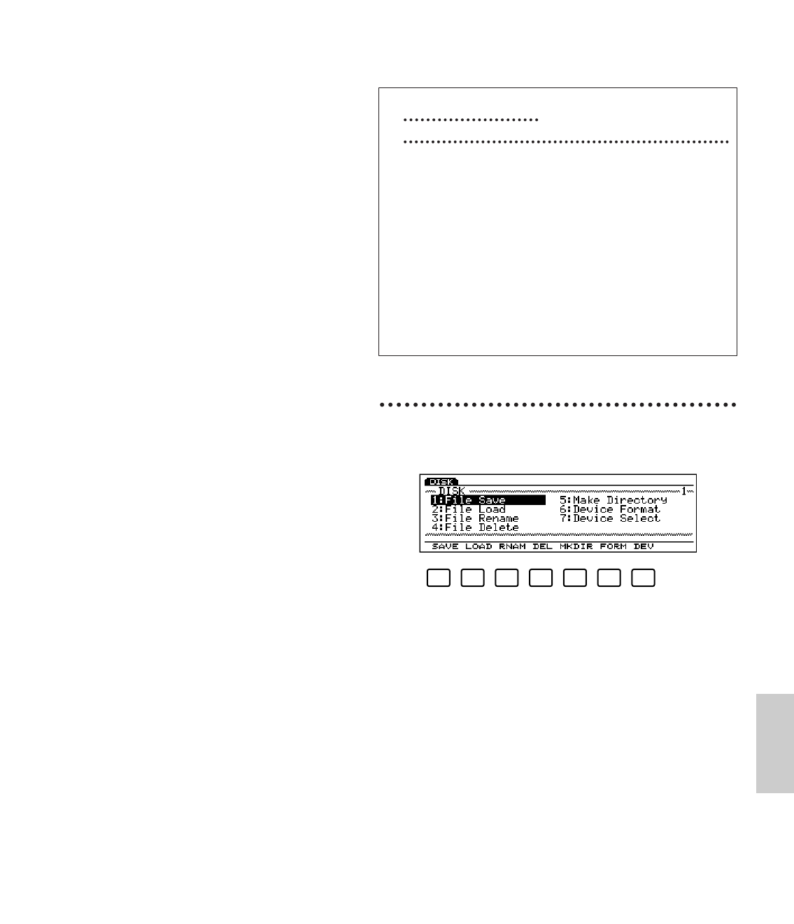
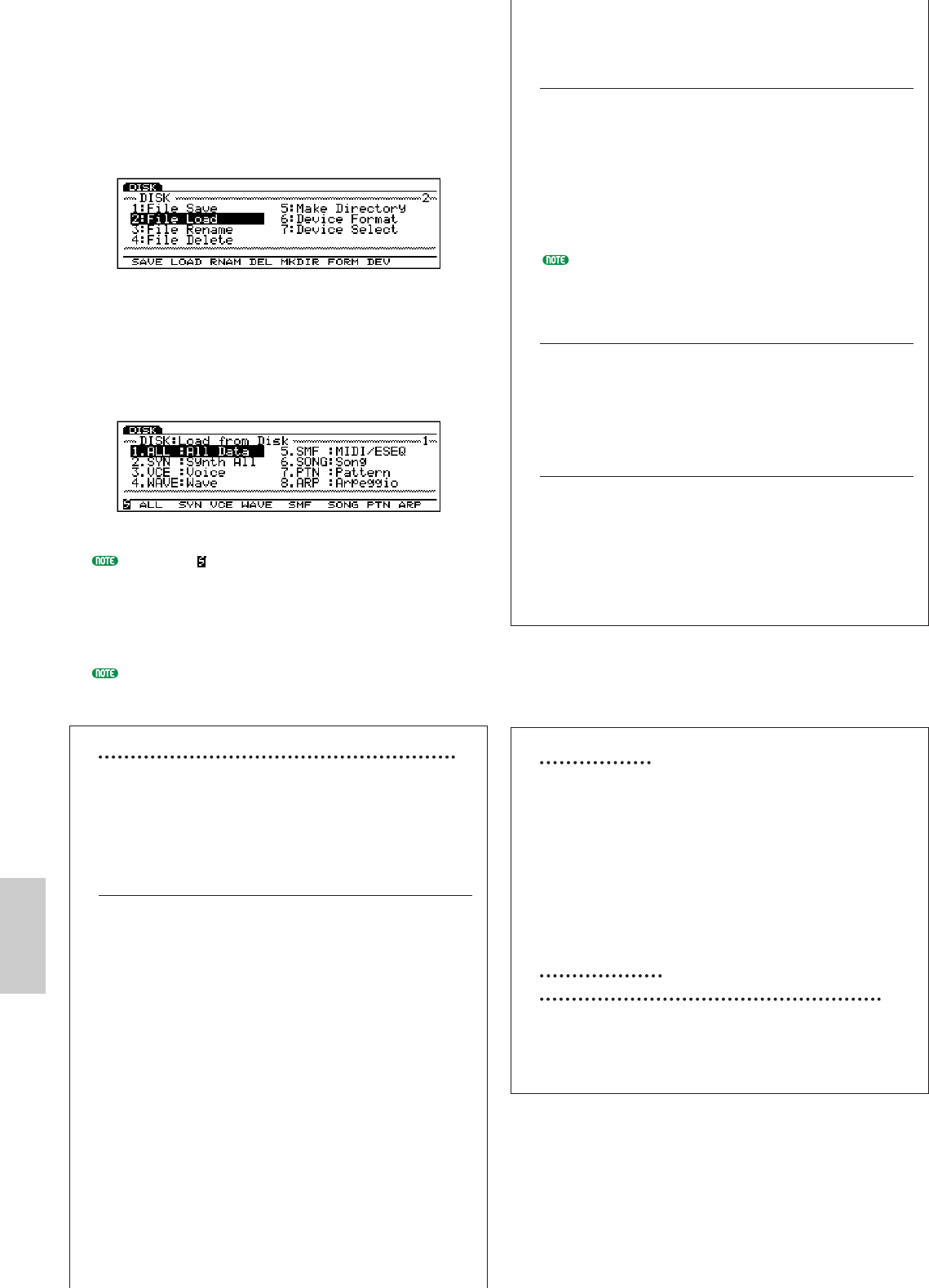
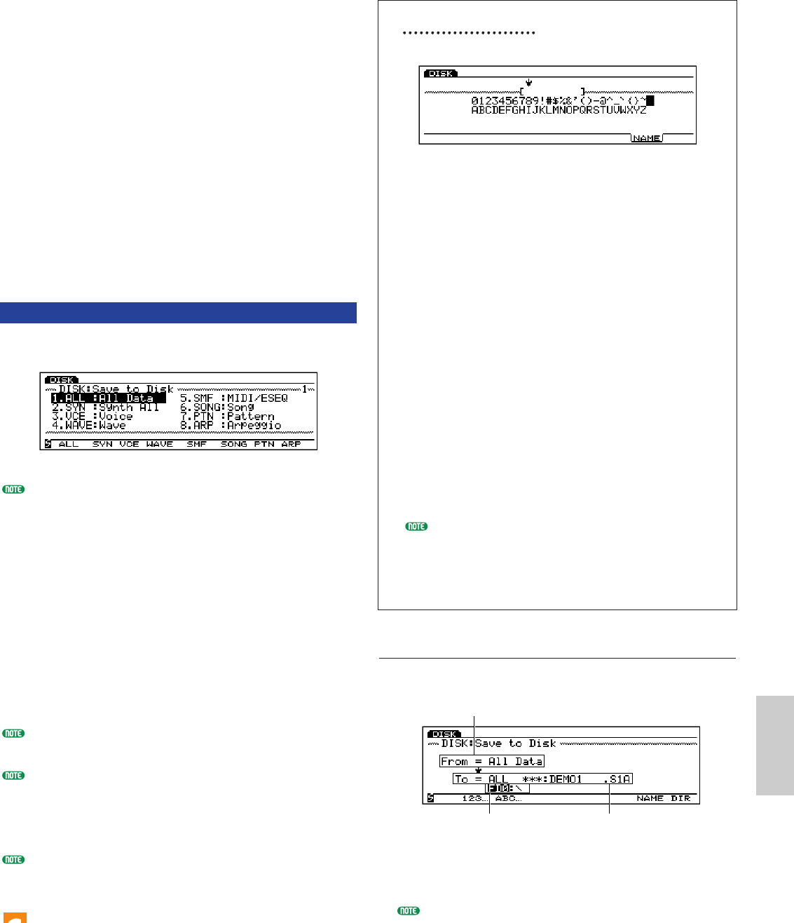
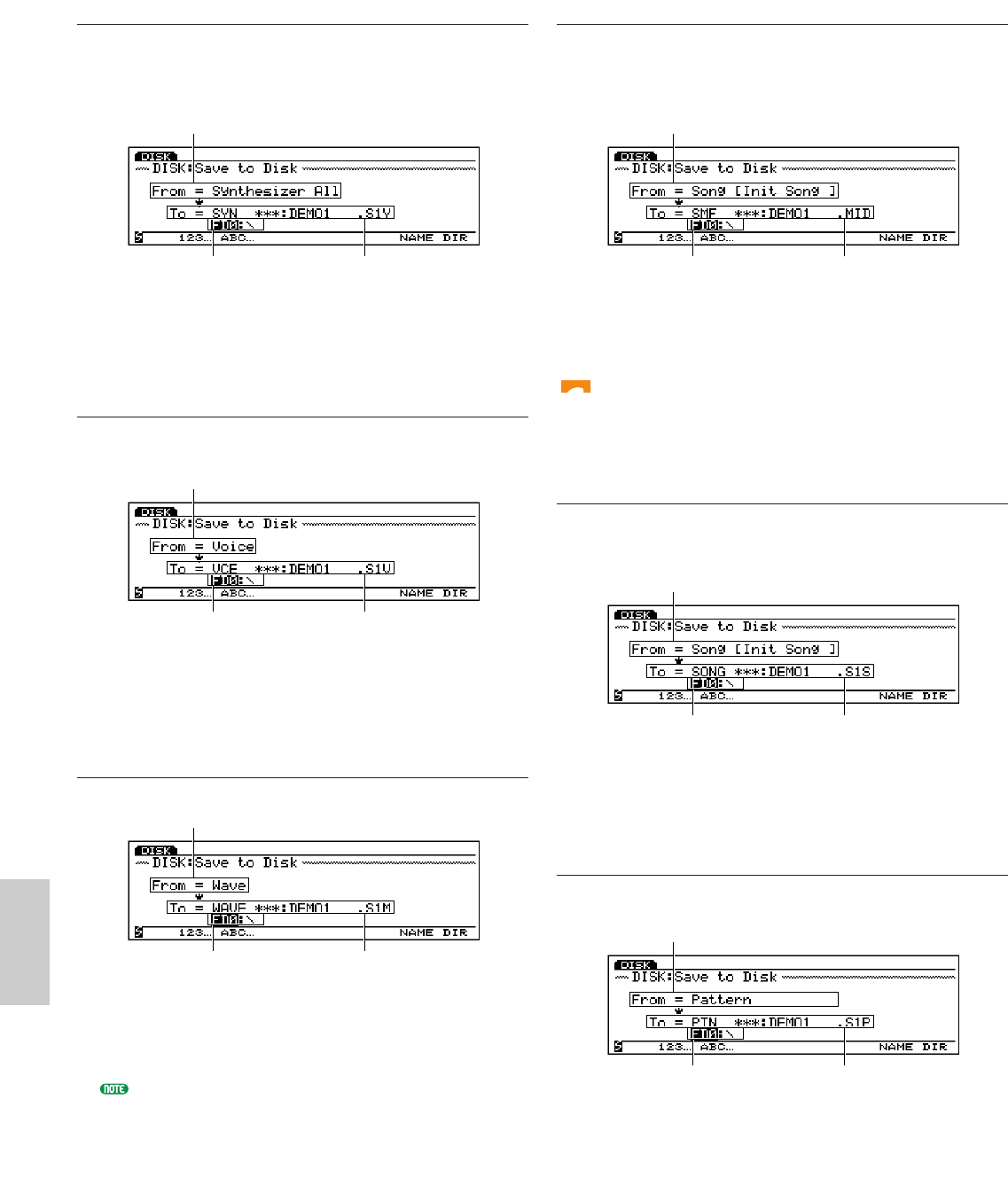
DISKFile Types
Functions
Others
UTILITY
CONTROLS
CONNECTORS & TERMINALS
DISPLAY
INCLUDED ACCESSORIES
OPTIONAL ACCESSORIES
POWER CONSUMPTION
OUTPUT IMPEDANCE
DIMENSIONS
WEIGHT
* Specifications and descriptions in this owner's manual are for information purposes only. Yamaha Corp. reserves the right to change or modify products or specifications at any time without
prior notice. Since specifications, equipment or options may not be the same in every locale, please check with your Yamaha dealer.
Libble takes abuse of its services very seriously. We're committed to dealing with such abuse according to the laws in your country of residence. When you submit a report, we'll investigate it and take the appropriate action. We'll get back to you only if we require additional details or have more information to share.
Product:
Forumrules
To achieve meaningful questions, we apply the following rules:
First, read the manual;
Check if your question has been asked previously;
Try to ask your question as clearly as possible;
Did you already try to solve the problem? Please mention this;
Is your problem solved by a visitor then let him/her know in this forum;
To give a response to a question or answer, do not use this form but click on the button 'reply to this question';
Your question will be posted here and emailed to our subscribers. Therefore, avoid filling in personal details.
Register
Register getting emails for Yamaha EX5R at:
new questions and answers
new manuals
You will receive an email to register for one or both of the options.
Get your user manual by e-mail
Enter your email address to receive the manual of Yamaha EX5R in the language / languages: English as an attachment in your email.
The manual is 7,23 mb in size.
You will receive the manual in your email within minutes. If you have not received an email, then probably have entered the wrong email address or your mailbox is too full. In addition, it may be that your ISP may have a maximum size for emails to receive.
If you have not received an email with the manual within fifteen minutes, it may be that you have a entered a wrong email address or that your ISP has set a maximum size to receive email that is smaller than the size of the manual.
The email address you have provided is not correct.
Please check the email address and correct it.
Your question is posted on this page
Would you like to receive an email when new answers and questions are posted? Please enter your email address.