polyprolene) or PVC-C (cross-linked polyvinyl chloride).
Any internal pipework should be of a diameter to match the
requirements of the condensate exit pipe on the appliance.
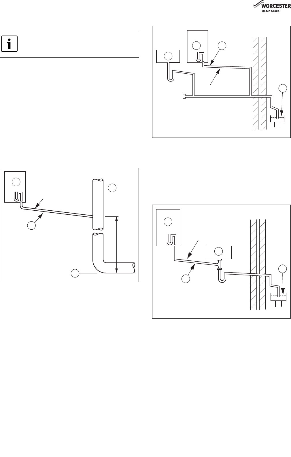
Termination to internal pipe
The condensate drain pipe should have a minimum outside diameter of
Ø21.5 mm with no length restriction. It should incorporate a trap with a
75 mm condensate seal and be connected to the stack at a point at least
450 mm above the invert of the stack. The trap built into the boiler will
provide this 75 mm (fig. 19) condensate seal.
The minimum distance between the condensate trap and the
condensate drain pipe is 2 cm. An air gap should be maintained between
the boiler condensate trap and the condensate pipework.
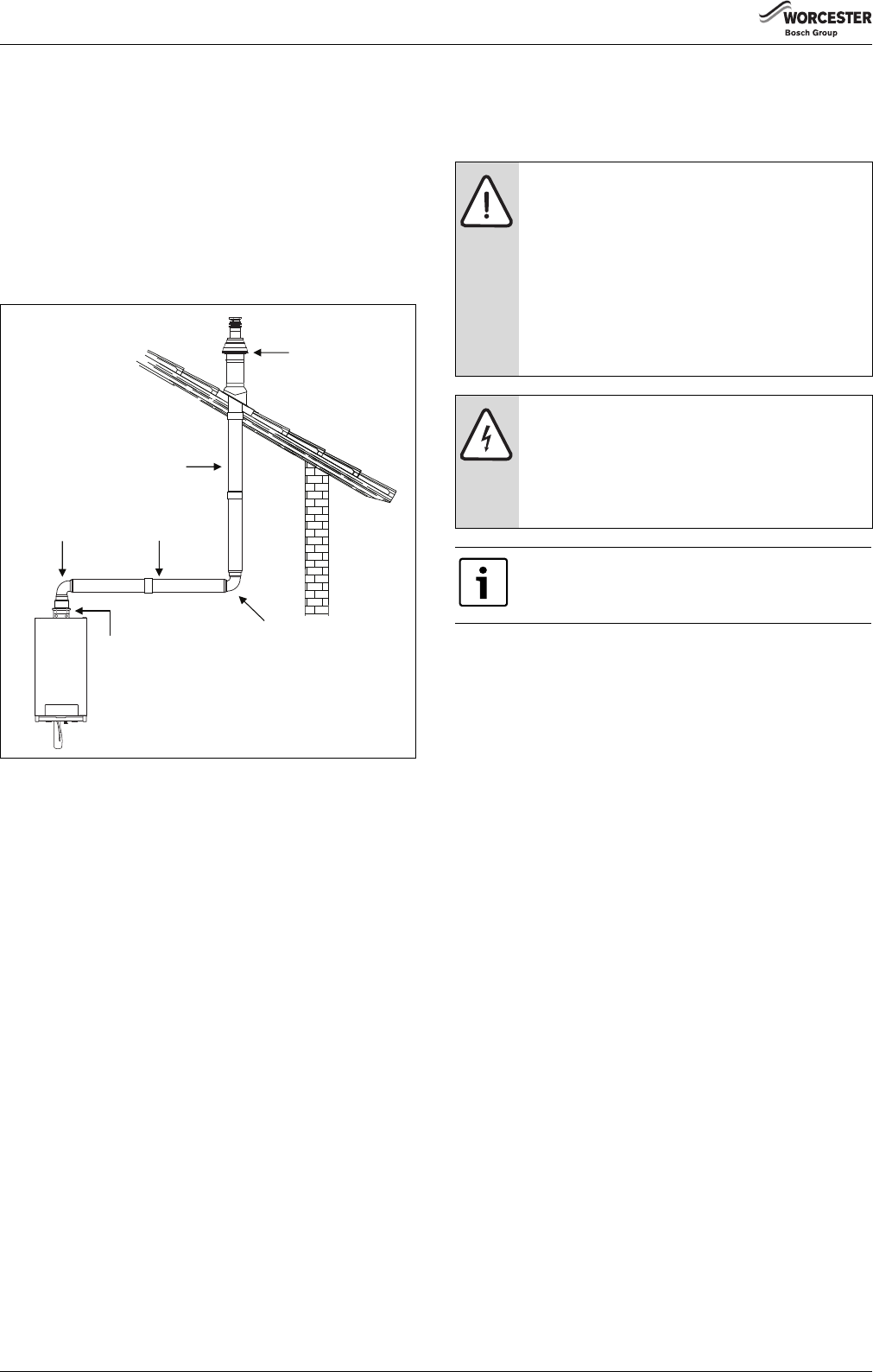
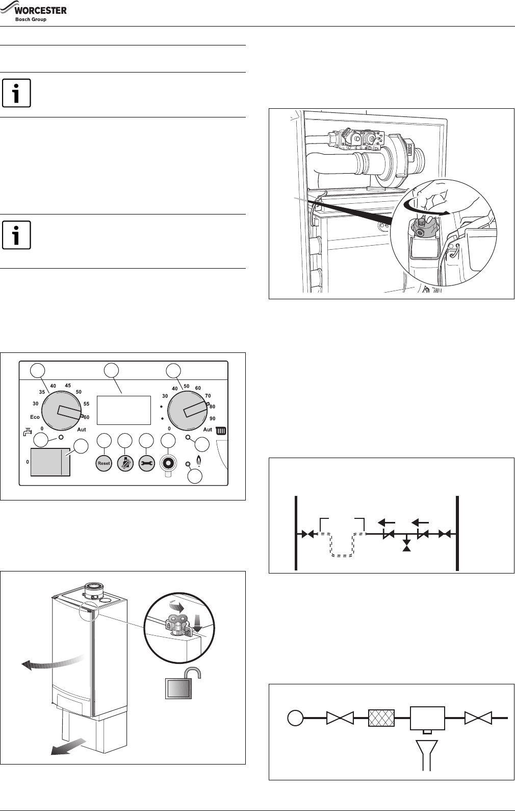
Fig. 19Termination of condensate drain pipe to internal pipe
[1]Boiler
[2]Internal soil and vent pipe
[3]Invert
[4]No length restriction
External termination via internal branch (e.g. sink waste)
The condensate drain pipe should have a minimum outside diameter of
Ø21.5 mm with no length restriction. The connection should preferably
be made downstream of the sink waste trap. If the connection is only
possible upstream, then an air break is needed between the 2traps.
This is normally provided by the sink waste pipe (fig. 20 and 21).
Fig. 20Internal termination of condensate drain pipe to external waste
point
[1]Sink
[2]Boiler
[3]No length restriction
[4]Open end of pipe direct into drain, below ground but above water
level
An air gap should be maintained between the boiler condensate trap and
the condensate pipework.
Fig. 21External termination of condensate drain pipe via internal
discharge branch (e.g. sink waste – proprietary fitting) and
condensate trap
[1]Sink
[2]Boiler
[3]No length restriction
[4]Open end of pipe direct into drain, below ground but above water
level
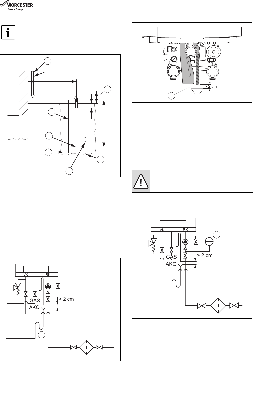
Condensate absorption point
The condensate drain pipe should have a minimum outside diameter of
Ø21.5 mm and the external pipe length should not be more than 3 m.
The condensate absorption point should be sited in a convenient
position as close as possible to the boiler but not in the vicinity of other
services. See fig. 22 for information.
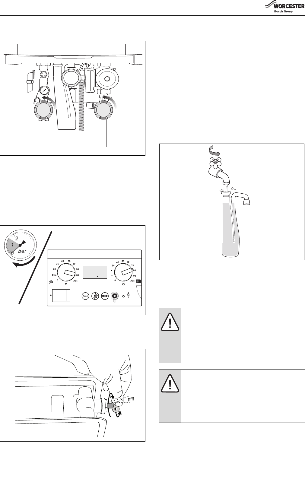
Ensure that the condensate trap is filled with water.
Ø21.5 mm min.
450 mm min.
6 720 648 726-019.1TD
4
3
2
1
Ø21.5 mm min.
4
3
2
1
6 720 648 726-020.1TD
Ø21.5 mm min.
4
3
2
1
6 720 648 726-021.1TD
Installation
6720813171 (2016/05)19
Fig. 22External termination of condensate drain pipe to absorption
point
[1]External length of pipe 3 m max.
[2]Plastic tube
[3]Bottom of tube sealed
[4]Limestone chippings
[5]Two rows of three 12 mm holes at 25 mm centres, 50 mm from
bottom of tube and facing away from house
[6]Hole depth
[7]Ground (either/or)
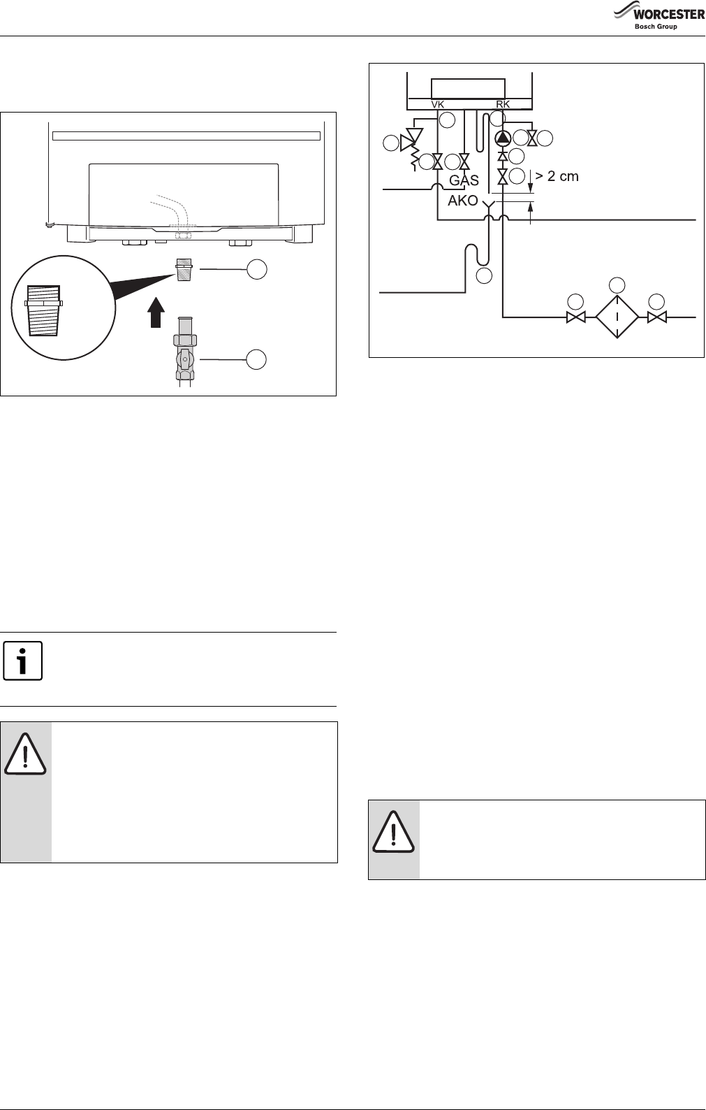
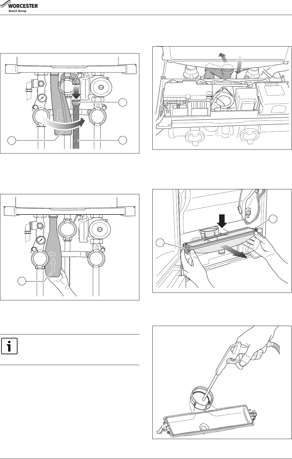
8.2.11Connecting the condensate drain pipe
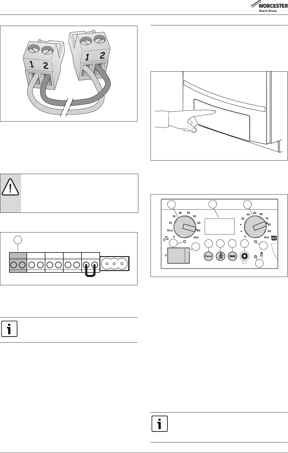
▶Connect the condensate drain pipe to the condensate trap
(fig. 23, [1] and fig. 24, [1]).
Fig. 23Connecting the condensate trap
[1]Condensate trap
Fig. 24Condensate drainage pipe
[1]Minimum distance > 2 cm
Observe the following regulations:
•The (local) waste water disposal regulations.
•The condensate trap in the connection kit must not be permanently
connected to the condensate drain pipe. The minimum distance
between the condensate trap and the condensate drain pipe is 2 cm.
An air gap should be maintained between the boiler condensate trap and
the condensate pipework.
8.2.12Connecting the expansion vessel in a single-boiler system
▶Connect the expansion tank to the boiler return (CHR). If a non-return
valve is available: connect the expansion vessel to the CH-side of the
non-return valve in the return circuit (fig. 25, [1]).
Fig. 25Connecting the expansion vessel in a single-boiler system
[1]Expansion vessel
When discharging condensate to an outside drain
caution must be taken to ensure blockage cannot occur
during freezing conditions. If this is likely to occur, the
use of a condensate trap is recommended.
Ø100 mm min.
400 mm min.
300 mm min.
25 mm min.
1000 mm min.
Ø21.5 mm min.
6 720 648 726-022.1TD
7
6
5
4
3
2
1
1
6 720 648 726-023.1TD
CAUTION: Damage to the installation due to faulty
pressure relief valve.
▶The expansion vessel must be of sufficient capacity.
1
6 720 648 726-024.1TD
1
6 720 648 726-025.1TD
Installation
6720813171 (2016/05)20
8.3Flue Installation
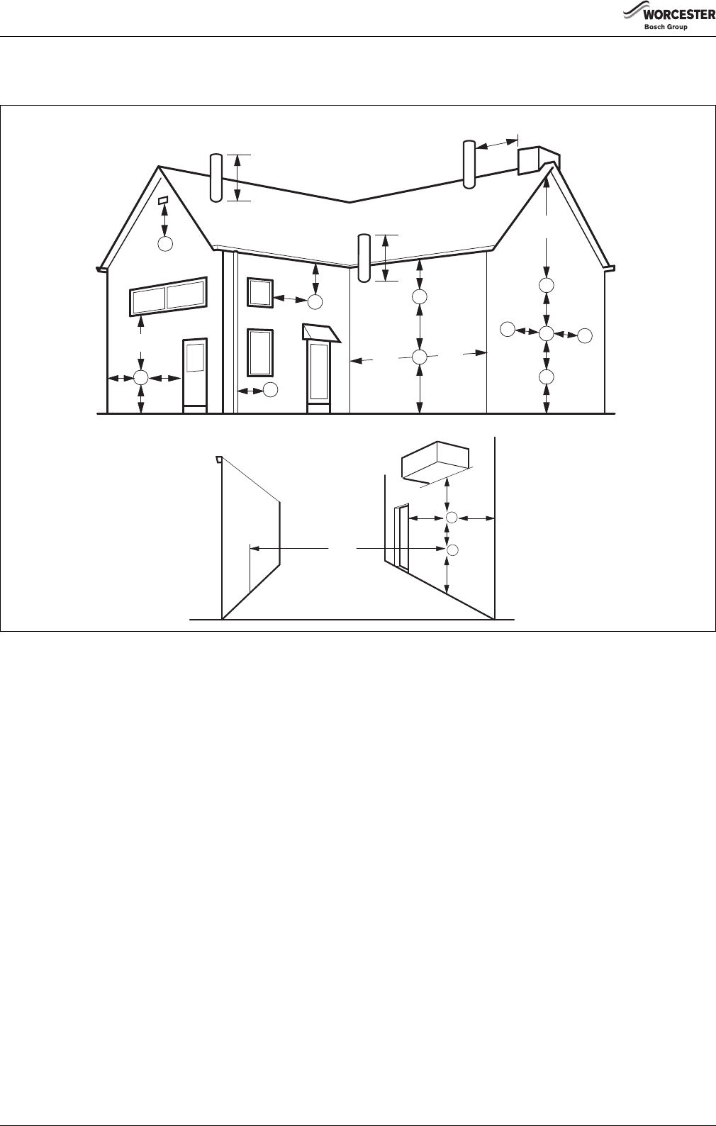
8.3.1Siting the flue terminal
Fig. 26Balanced flue terminal position
Terminal positionMinimum spacing [mm]:
[A]Directly below, above or alongside an opening window, air vent or other ventilation opening300
[B]Below guttering, drain pipes or soil pipes200
[C]Below eaves200
[D]Below balconies or a car port roof Not recommended!200
[E]From vertical drain pipes or soil pipes150
[F]From internal or external corners300
[G]Above adjacent ground, roof or balcony level300
[H]From a surface facing the terminal600
[I]From a terminal facing a terminal1200
[J]From an opening in a car port (e.g. door or window) into dwelling. Not recommended!1200
[K]Vertically from a terminal on the same wall1500
[L]Horizontally from a terminal on the wall300
[M]Adjacent to opening300
[N]Above intersection with roof300
[O]From a vertical structure on the roof500
The flue for installations in excess of 70 kW must be installed in
accordance with the recommendations of IGE UP10.
Pluming will occur at the terminal so terminal positions where this could
cause a nuisance should be avoided.
The air supply and the flue gas exhaust must meet the applicable general
regulations. Please consult the instructions provided with the flue
terminal kits prior to installation.
The boiler must be installed so that the terminal is exposed to external
air.
It is important that the position of the terminal allows the free passage of
air at all times.
Minimum acceptable spacing from the terminal to obstructions and
ventilation openings are specified in fig. 26.
If the lowest part of the terminal is less than 2 metres above the level of
the ground, balcony, flat roof or place to which any person has access,
the terminal must be protected by a guard.
Ensure that the guard is fitted centrally.
The flue assembly shall be so placed or shielded as to prevent ignition or
damage to any part of the building.
The flue outlet duct and the terminal of the boiler must not be closer
than 25 mm to combustible material. Detailed recommendations on the
protection of combustible material are given in IGE UP10.
A
F
M
G
M
B,C
F
F
B,C
K
G
K
K
G
C
L
L
A
N
N
O
E
FJ
K
G
D
H, I
6 720 648 726-026.1TD
Installation
6720813171 (2016/05)21
If this could occur the appliance must be turned off, and labelled as
unsafe until corrective action can be taken.
8.3.2Air supply and flue gas exhaust in a room sealed installation
A ventilation cover is integrated into the condensing gas system boilers.
This cover houses a number of components, such as the burner and the
heat exchanger. Since this ventilation cover is part of the air supply
system, it is vital that it is always installed correctly.
To ensure optimal operation, the appliances must be connected to a
Worcester horizontal or vertical flue terminal. These terminals have been
developed specifically for Worcester condensing gas boilers and have
been comprehensively tested for trouble free operation when correctly
installed.
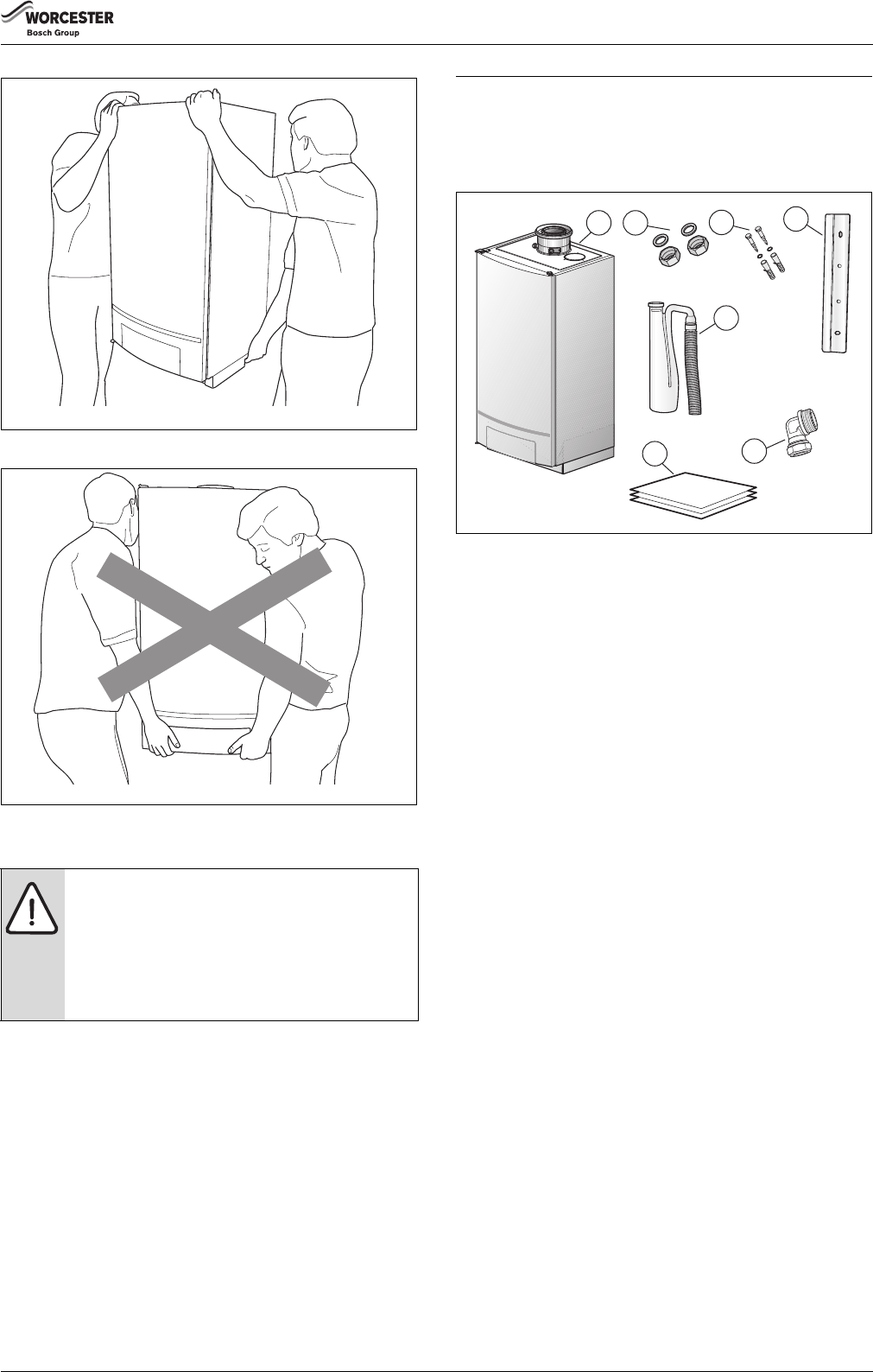
Standard horizontal flue pack (fig. 27) for GB162-80/100:
•1: Flue turret 100/150;
•2: Horizontal flue terminal 100/150;
•3: Flue finishing kit.
Standard horizontal flue pack (fig. 27) for GB162-50/65:
•1: Flue turret 80/125;
•2: Horizontal flue terminal 80/125;
•3: Flue finishing kit.
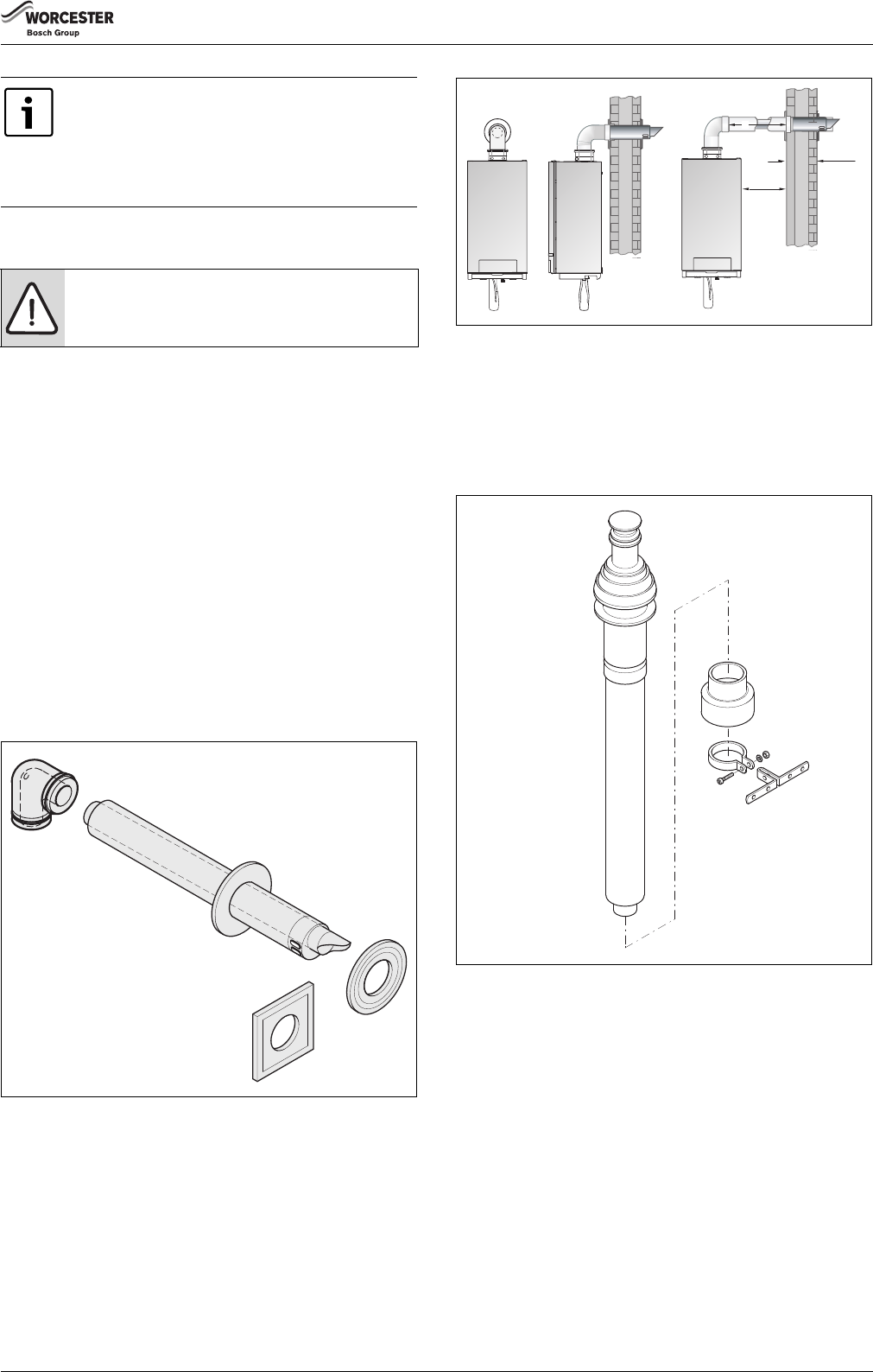
Fig. 27Standard horizontal flue pack
Fig. 28Side flue and rear flue installation
Standard vertical flue pack (fig. 29) for GB162-80/100:
•Concentric vertical flue pipe 100/150;
•Wall clamp.
Standard vertical flue pack (fig. 29) for GB162-50/65:
•Concentric vertical flue pipe 80/125;
•Wall clamp.
Fig. 29Standard vertical flue pack
It is very important to ensure, that products of
combustion discharging from the terminal cannot re-
enter the building or any other adjacent building.
Through ventilators, windows, doors, other sources of
natural air infiltration, or forced ventilation/air-
conditioning.
DANGER:
▶Only use Worcester flue gas systems. As other flue
gas systems are not tested with this appliance.
6 720 648 726-027.1TD
415 mm
8 mm
L
6 720 648 726-028.1TD
6 720 648 726-029.1TD
Installation
6720813171 (2016/05)22
8.3.3Maximum Flue length (L)
The maximum pipe length (L) of the air supply and flue gas exhaust pipes
for the condensing gas system boilers is determined by the total
pressure loss of all components in the flue system.
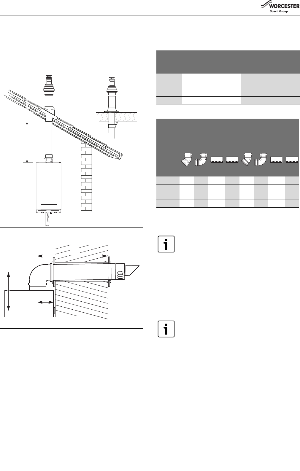
Maximum length of horizontal or vertical extensions for 100/150 flue
system (fig. 30 and fig. 31). For flue length see table 6.
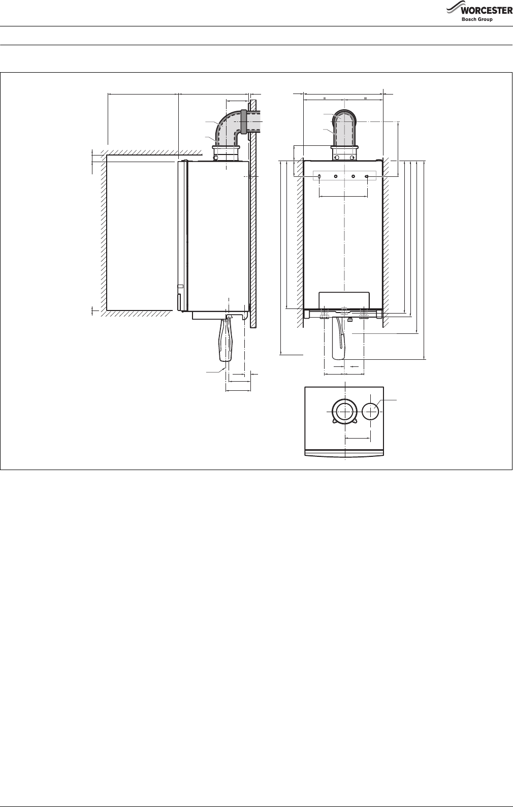
Fig. 30Vertical flue length
Fig. 31Horizontal flue length
[A]Distance from centre of flue to inside rear wall
[B]Distance from centre wall bracket to centre of flue elbow
[L]Distance from centre of flue to outside wall
Take the flue pipe clearances into account when planning the layout of
the place of installation (subsection 8.3.1: “Siting the flue terminal”
on page 20).
Maximum wall thickness without extensions is 415 mm. Maintain a
minimum side clearance of 8 mm (fig. 28).
8.3.4Additional flue parts
The additional flue parts listed can be ordered from your supplier.
Flue size 100/150 and 80/125
Weathering slates for 100/150 and 80/125
Flat roof, pitched roof.
8.3.5Standard 100 mm flue systems
The standard concentric flue system provides for a max. horizontal
straight length (table 6, subsection 8.3.4). Full instructions for
fitting this flue are in subsection 8.3.6: “Installation of the horizontal
flue” on page 23.
L
6 720 648 726-030.1TD
A
L
B
6 720 648 726-031.1TD
GB162Maximum flue length [m]
concentric flue system
100/15080/125
50207,7
65207.7
8018–
10018–
Table 6Max. flue lengths, incl. wall/roofterminal in meters
GB162Reduced flue length [m]
1)
1)For every bend or extension the max. flue length (L) has to be reduced.
concentric flue system
100/150
concentric flue system
80/125
bendextensionbendextension
45°90°0.5m1m45°90°0.5m1m
501.22.10.51.00.91.90.51.0
651.22.10.51.00.91.90.51.0
801.22.10.51.00.91.90.51.0
1001.22.10.51.00.91.90.51.0
Table 7Reduced flue lengths in meters
The total reduction length must never exceed the
maximum flue length.
Important: Any horizontal flue system fitted to a
condensing boiler must be inclined towards the
appliance at an angle of 52 mm per metre length to
prevent condensate dripping from the flue terminal.
This means that the clearance above the appliance must
be increased to match the duct length. See fig. 6 on
page 12.
Installation
6720813171 (2016/05)23
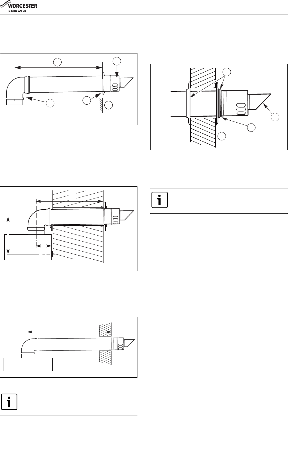
8.3.6Installation of the horizontal flue
The standard flue is suitable for lengths up to 660 mm ( fig. 32).
For longer flue runs up to 29.0 m for flue system 100/150 and 7.3 m for
flue system 80/125, flue extensions are available (accessory).
Fig. 32Installation with horizontal flue gas terminal
[1]maximum length
[2]terminal assembly
[3]90° bend
[4]finishing kit
[5]outer wall
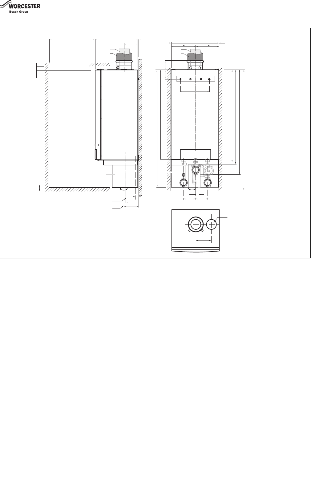
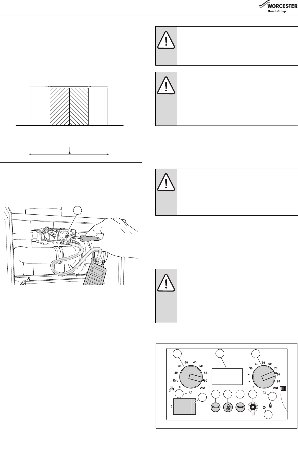
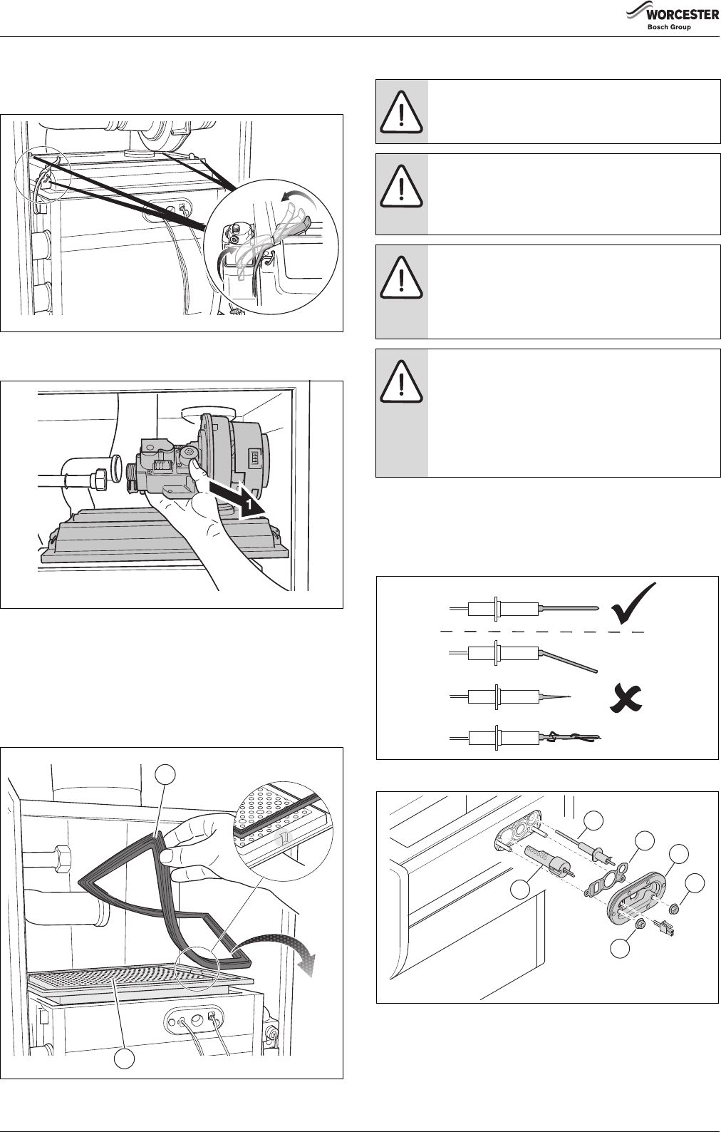
8.3.7Flue pipe preparation and assembly
▶Measure the flue length L. Refer to figures 33 and 34.
Fig. 33Flue length - rear
[A]150 mm without the use of a wall spacing frame
[]185 mm with the use of a wall spacing frame
[B]337.5 mm for Ø 80/125 mm horizontal flue
[]339.5 mm for Ø 100/150 mm horizontal flue
[L]flue length
Fig. 34Flue length - side
▶Mark off the lengths shown onto the pipe and cut to length. The cuts
must be square and free from burrs. Terminal assembly outer (air)
pipe - L-70 mm, inner (flue) pipe - L-50 mm. The measurement is
made from the ridge at the terminal indicating the outer face of the
wall. Refer to figure35. Extension outer flue - L-70 mm, inner flue - L-
50 mm. The measurement is from the formed end.
Fig. 35Flue terminal position
▶Assemble flue system completely. Push the flue fully together.
The slope of the terminal outlet must face downwards ( fig. 35,
item 1). The assembly will be made easier if a solvent free grease is
lightly applied to the male end of the flue.
▶Push the assembly through the wall and slide the terminal onto the
flue connector. Ensure that the terminal is fully entered into the
socket on the boiler.
▶From the outside fix the flue finishing kit to the terminal and, after
ensuring the flue is properly inclined towards the boiler, fix the
finishing kit to the wall. If the terminal is within 2 m of the ground
where there is access then an approved terminal guard must be
fitted. The guard must give a clearance of at least 50 mm around the
terminal and be fixed with corrosion resistant screws.
8.4Flue gas connection
8.4.1Open flue operation
If operation independent of room air is not desired or not possible due to
local conditions, the boiler can be set up for operation to take air for
combustion from the room (contact Worcester Technical).
The boiler is factory-fitted with a concentric connection.
An air intake strainer basket can be used for operation dependent on
room air. This prevents falling dirt from entering the boiler (contact
Worcester Technical; accessory).
8.4.2Room sealed operation
The boiler can be connected to a concentric flue gas system.
The boiler is factory-fitted with a concentric connection.
8.4.3Flue material
When using plastic flue material, PPS is recommended.
8.4.4Calculating the air intake and flue gas pipe dimensions
The total reduced pipe length is calculated from the sum of the reduced
length of the horizontal and vertical flue ducting and the reduced length
of every elbow (table 7).
The total reduced pipe length must be less than the maximum pipe
length ( table 6).
See also the next example.
The flue must be inclined from the boiler.
6 720 648 726-032.1TD
5
4
3
2
1
A
L
B
6 720 648 726-031.1TD
L
6 720 648 726-034.1TD
An inner flue finishing kit is provided which should be
fitted to the ducts before assembly.
6 720 648 726-035.1TD
4
3
2
1
Installation
6720813171 (2016/05)24
Example of a flue design calculation for concentric flue system
100/150 using length method
Boiler: GB162-80
Flue system: concentric 100/150
Maximum length: 18 m.
Here we have:
•4 meter pipe (2 x 2 m)4.0 m
•2 x 90° bends (2 x 2.1 m)4.2 m
The total length of this flue system =8.2 m
Sum of length (8.2 m) < maximum length (18 m) robust flue design!
Fig. 36Example 1
8.5Electrical connections
When connecting the electrical components, observe the wiring
diagram, the installation and servicing instructions of the relevant
product.
6 720 648 726-036.1TD
Pipe=2m
Pipe=2m
Roofterminal
90° bend
Length=21m
90° bend
Length=21m
Maximum length
allowed after the
boiler (GB162-80)
18 m
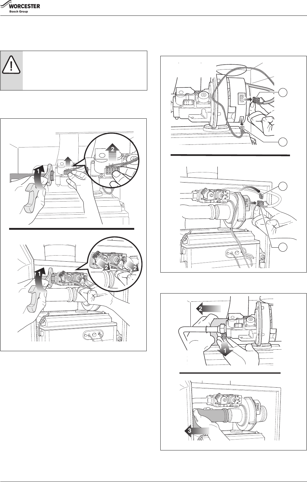
WARNING: Damage to the installation due to short
circuits.
To prevent electrical components from short-circuiting,
only use:
–original cables and wiring supplied by the
manufacturer.
–single core cable.
▶Use cable of at least 0.75 mm².
▶If the mains lead has to be replaced, you may only use
an original manufacturer-supplied mains lead.
DANGER: Danger of fatal accident due to electric
current when the boiler is open.
▶Before opening the boiler: Isolate the mains supply.
▶Secure the heating system so that it cannot be
switched on again unexpectedly, pulling the mains
plug from the wall socket.
The 230V converter can only be used for the
GB162-50/65 appliance.
Installation
6720813171 (2016/05)25
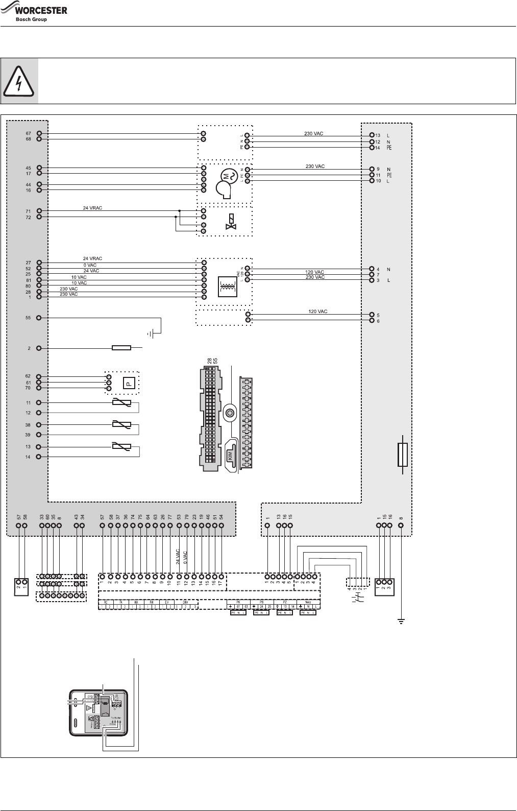
8.5.1Electrical wiring diagram
Fig. 37Electrical wiring diagram
WARNING:
▶Do not directly connect a 230 V thermostat to this boiler. Use the grey 230V connection box (supplied with GB162-50/65).
Earth
Ionisation
Pressure
sensor
Return sensor
Safety-temperature sensor
Flow sensor
81-pole connector
Pin 81
Pin 1
Pin 1
Pin 16
16-pole connector
16-pole connector
(AC 120 V and AC 230 V)
81-pole connector
(AC 0, 10, 24 and 230 V)
Connection
for pump in
connection kit
(accessory)
Fan
Gas valve
Transformer
Glow
ignitor
UBA 3.0 mounting base
230 VAC
function modules
230 VAC
function modules
Earth
Mains switch
Mains connection
230 VAC 50Hz,
max. permissible: 10 A
Outdoor-temperature
sensor
On/Off temperature
controller,potential free
DHW sensor
External switch contact
potential free, e.g.
for floor heating
External three-way valve
Switch contact
External connection for professional use
External heating
pump 230 VAC
max. 250 W
DHW pump
230 VAC max. 250 W
DHW circulation pump
230 VAC max. 250 W
greengraylilacwhite
greengrayredturquoiseorangeblue
FUSE 5 slow blow
sand filled
Room controller RC
and EMS bus
Connector for
BC10 basic controller
BUS
function modules
b)
The 230 Volt converter is only applicable for Logamax plus GB162-50/65
a) Connection to the external pump is only possible if no internal pump
has been integrated in the connection kit.
Volt free
external control
device
external
230V controls
2
1
b)
a)
230 Volt converter
6720813171-1.1TD
IMPORTANT: The wires in this mains lead are coloured in accordance with the following code: GREEN AND YELLOW - EARTH; BLUE - NEUTRAL; BROWN - LIVEAs the
colours of the wires in the mains lead of the appliance may not correspond with the coloured markings identifying the terminals in your connector proceed as follows:
The wire coloured green and yellow must be connected to the terminal on the connector marked with the letter E or by the earth symbol or coloured green or green-and-
yellow. The wire coloured brown, must be connected to the terminal marked with the letter L or coloured red. The wire coloured blue must be connected to the terminal
marked with the letter N or coloured black.WARNINGTHIS APPLIANCE MUST BE EARTHED. Ensure that your appliance is connected correctly - if you are in any doubt
consult a qualified electrician.For location of individual components, see service section and the exploded views in this manual.
Installation
6720813171 (2016/05)26
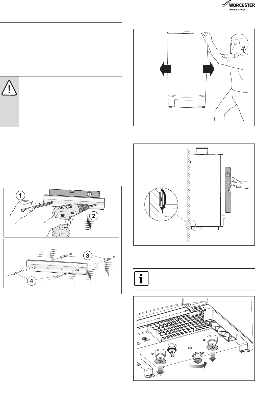
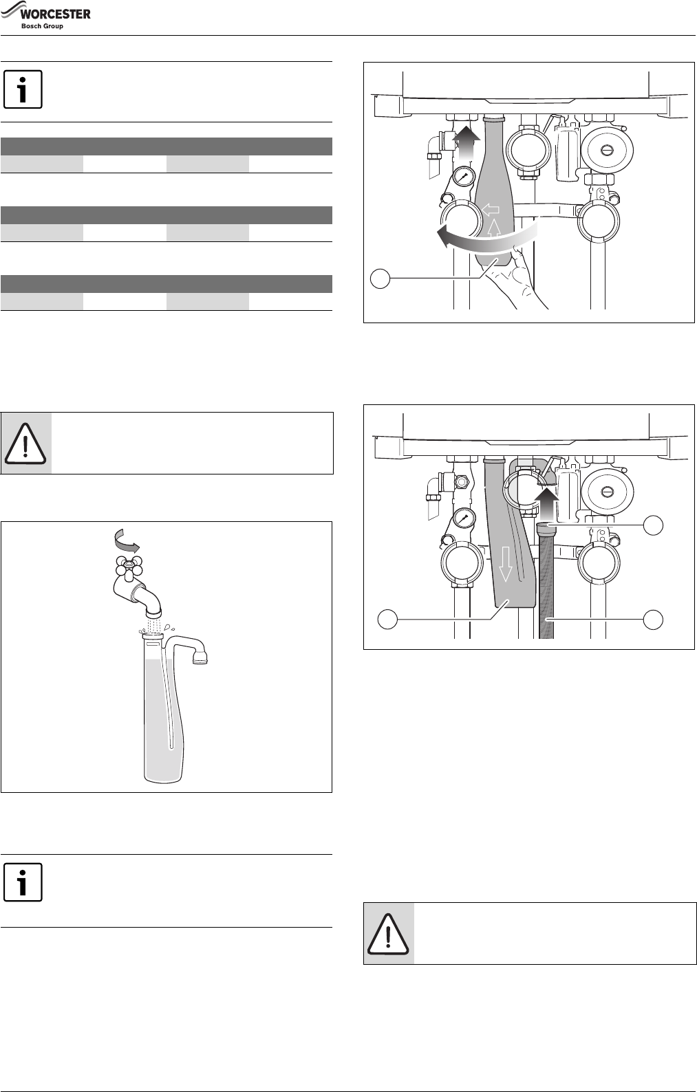
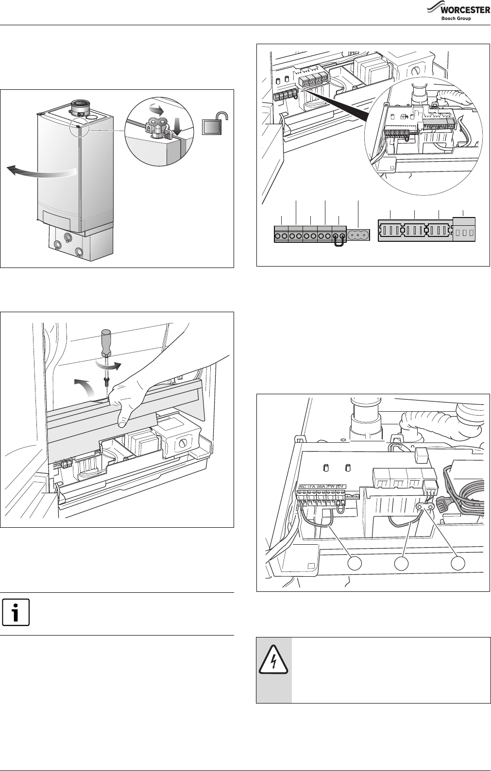
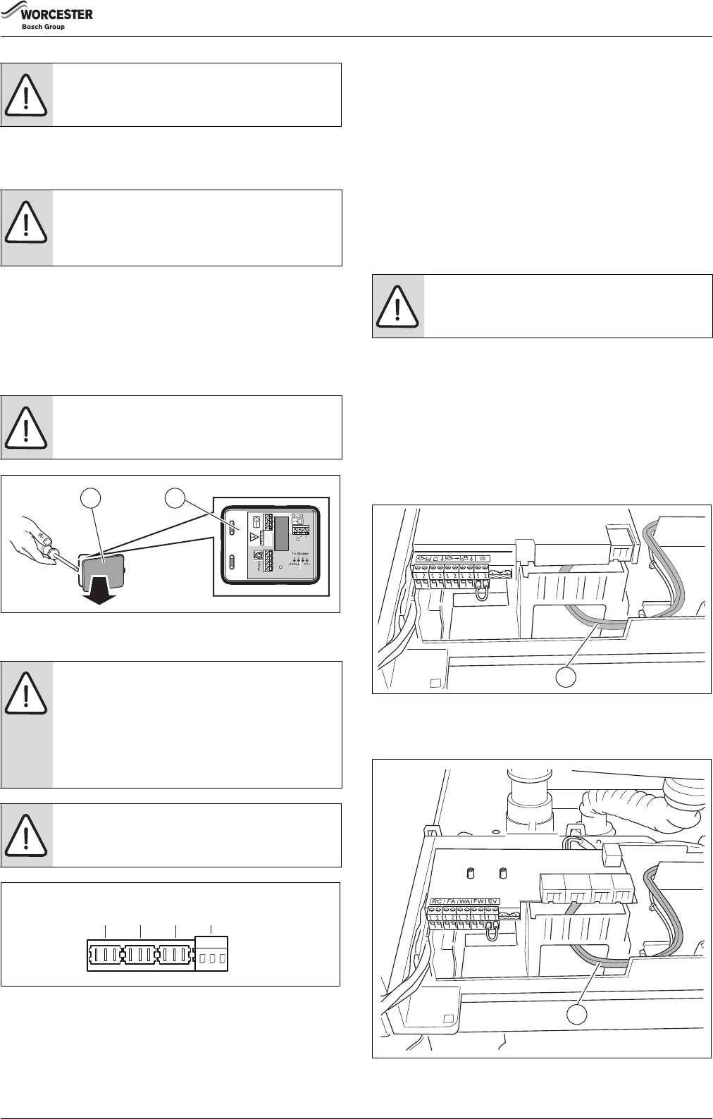
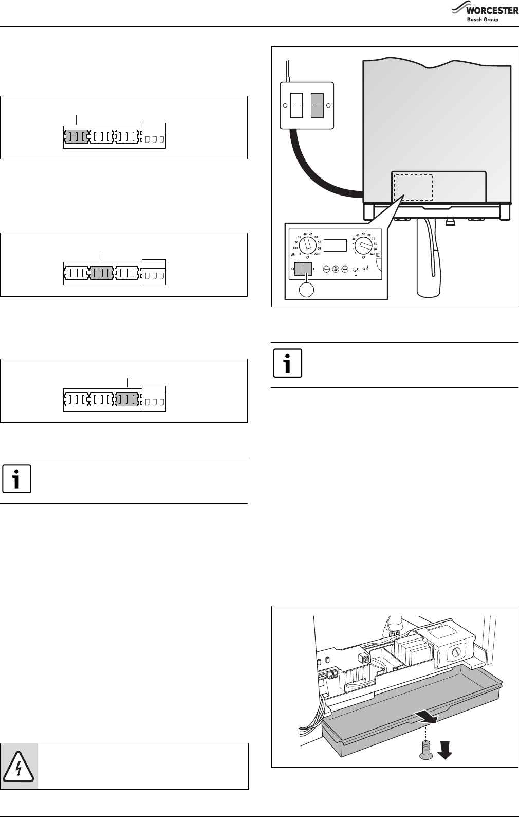
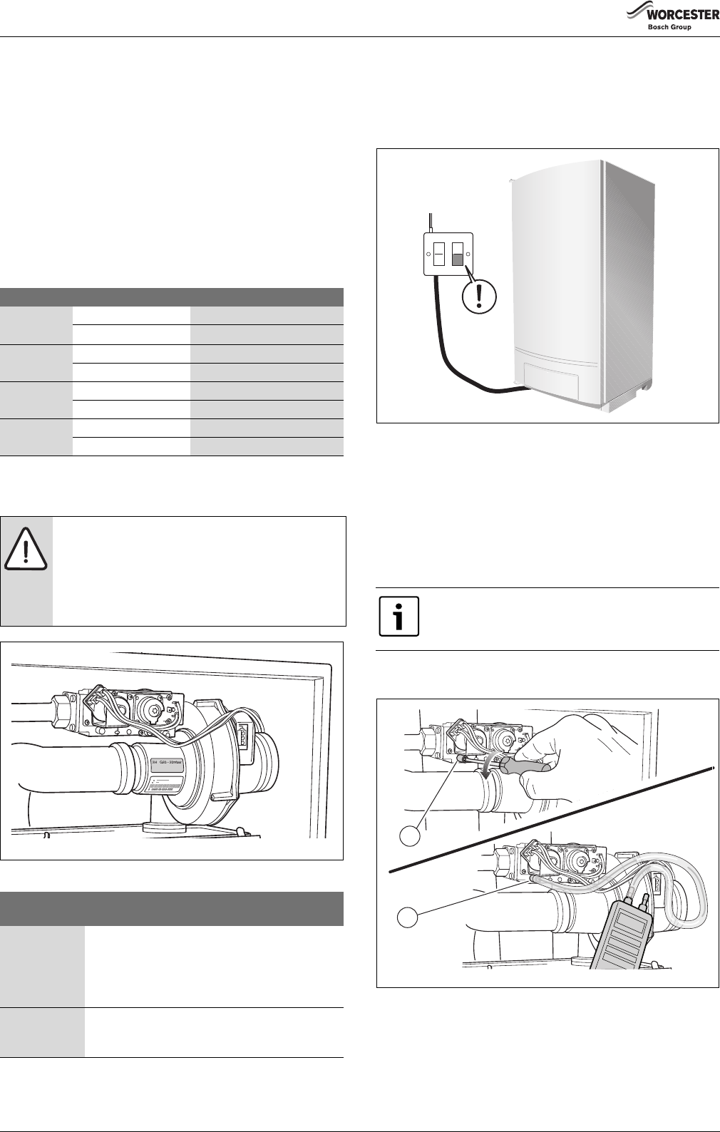
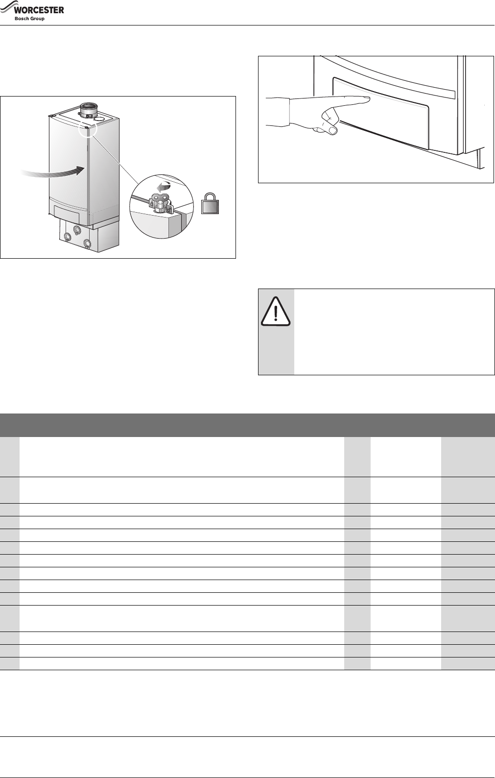
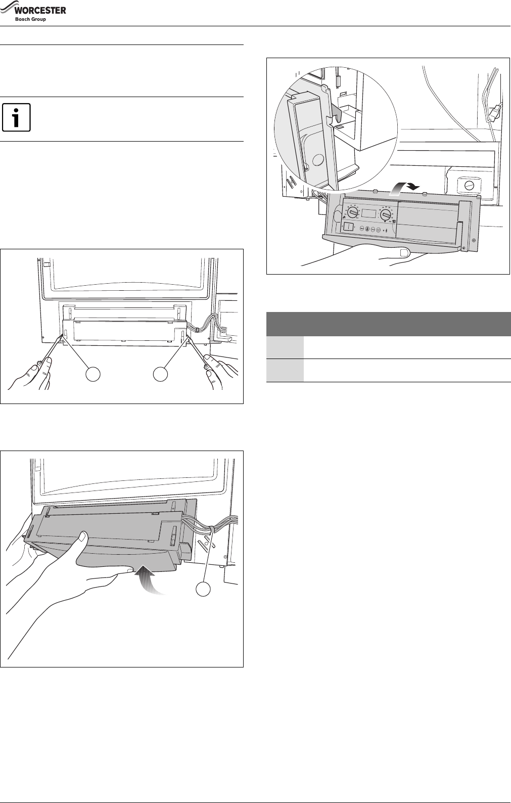
8.5.2Terminal strip connections
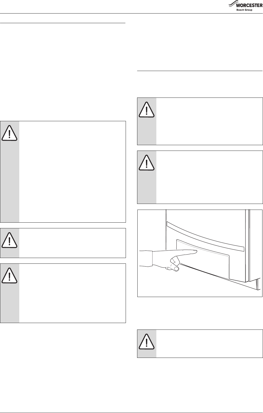
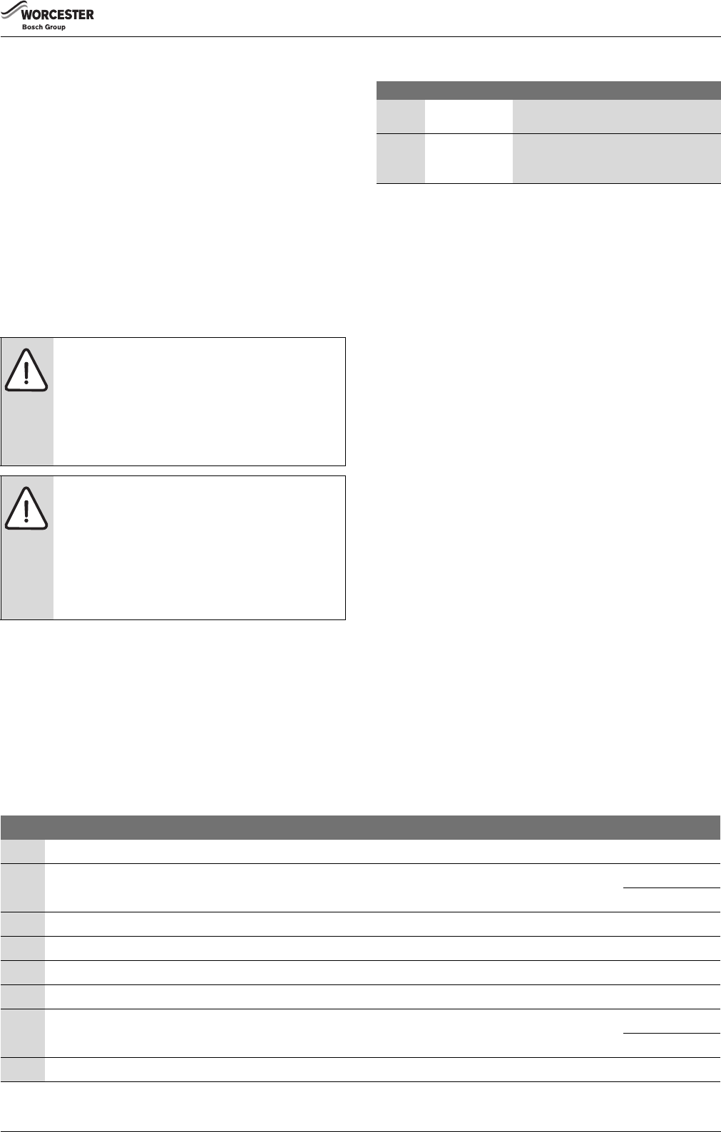
▶Turn the vent key through a quarter rotation to undo the boiler door
lock (fig. 38, see detailed picture).
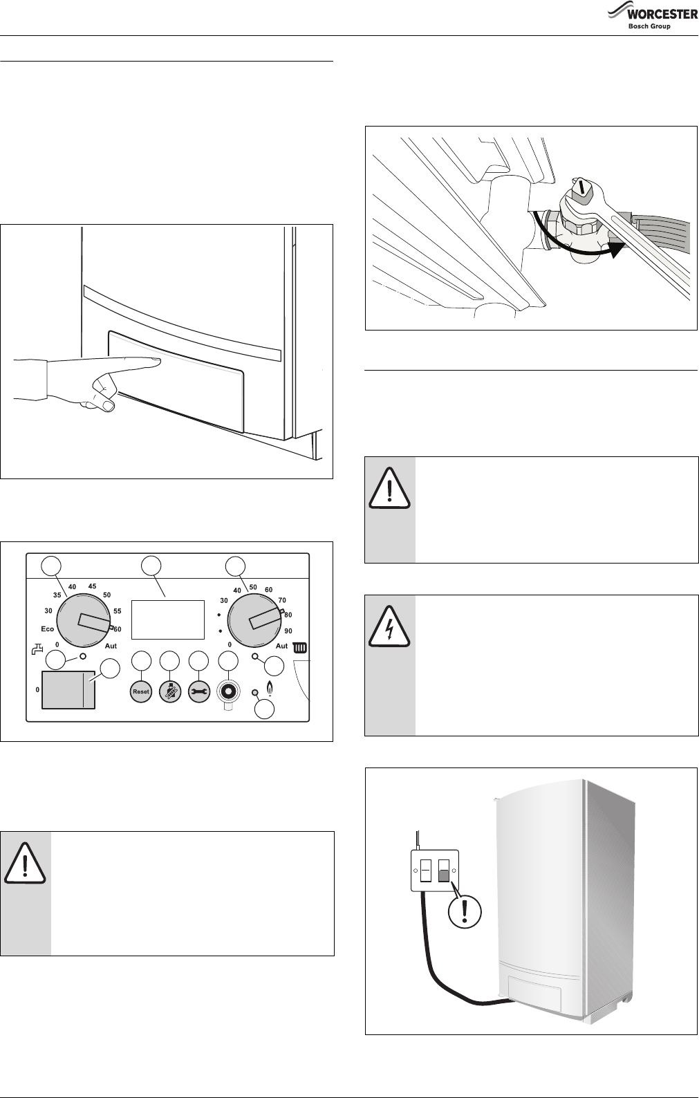
▶Push the fastener down (fig. 38) and open the boiler door.
Fig. 38Open the boiler door
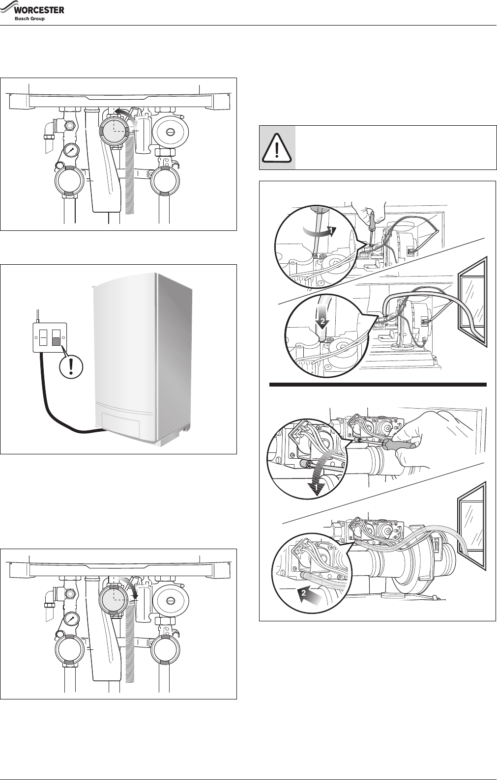
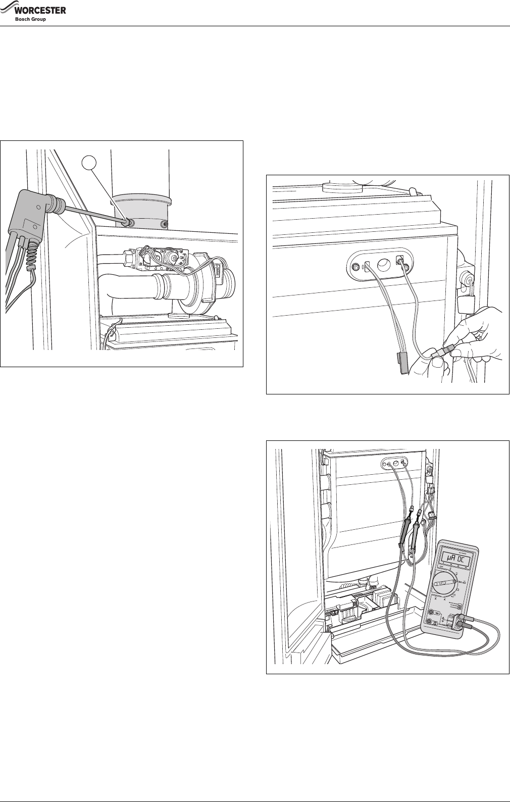
▶Undo 1 screw to release the cover over the electrical connections
and pull the cover upwards (fig. 39).
Fig. 39Pull up the cover over the electrical connections
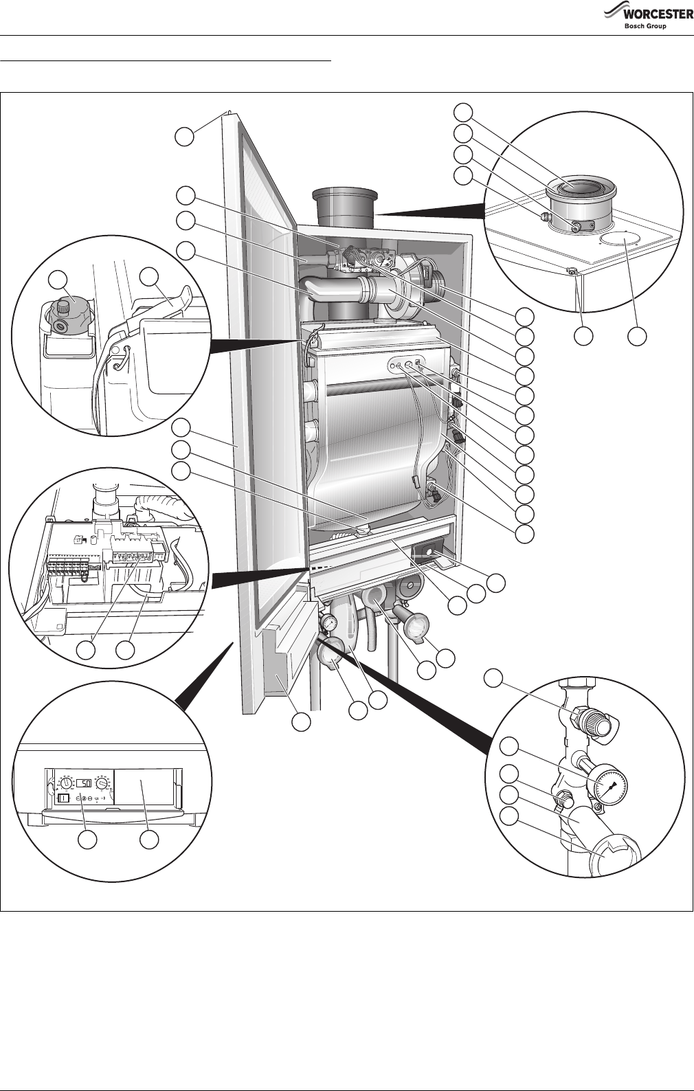
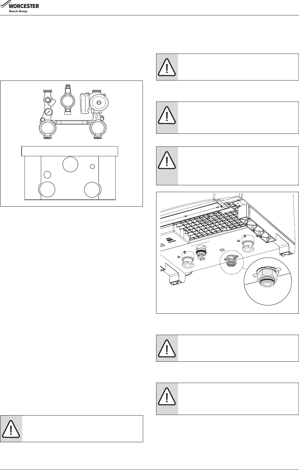
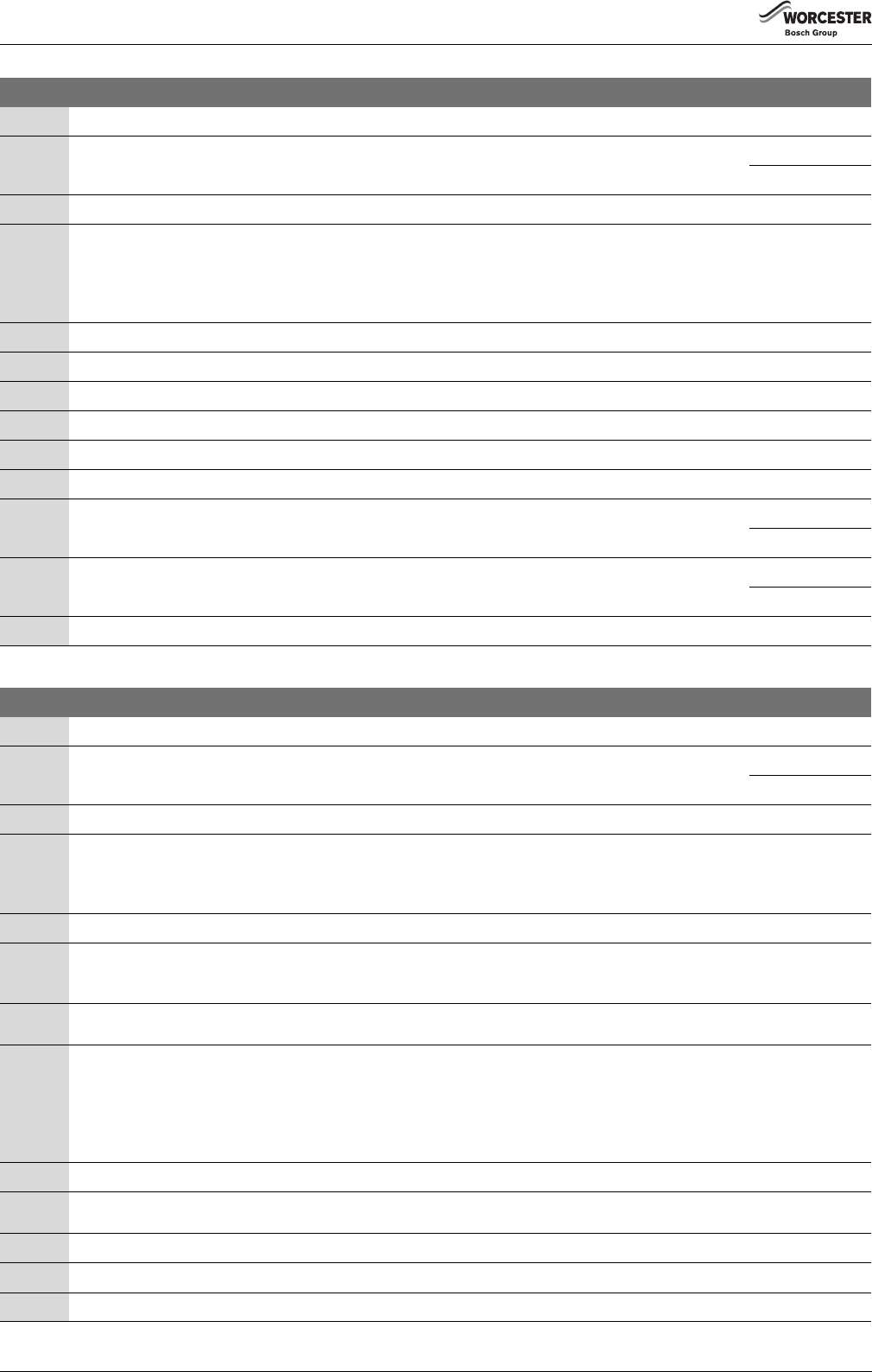
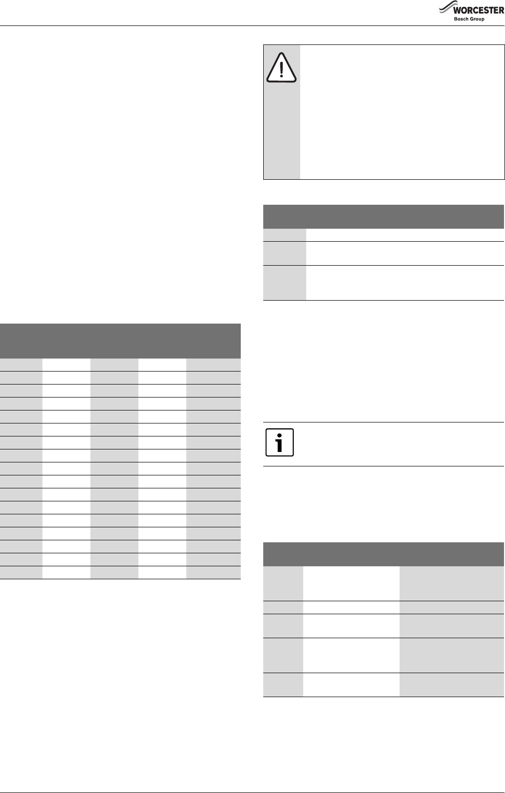
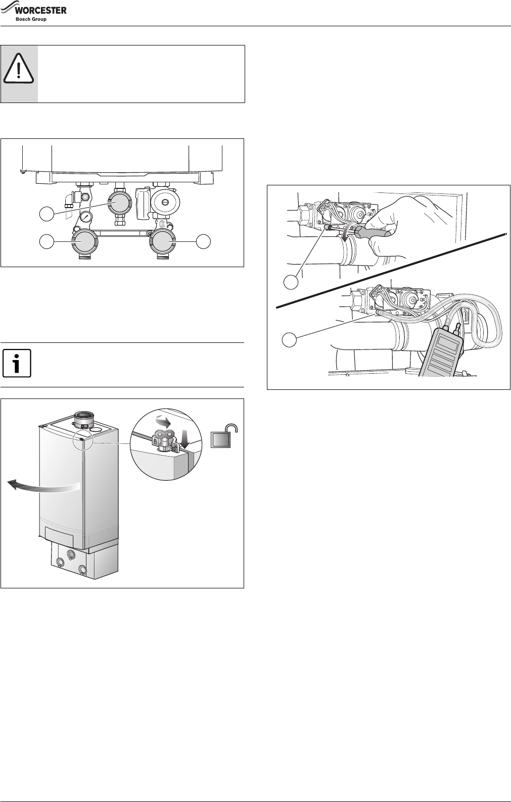
The terminal strip in the boiler (fig. 40) has a number of terminals to
connect internal and external electrical components. The listing below
shows which components must be connected to which terminals
(section 7.5.4, page 36).
Fig. 40Terminal strip
[A]Low-voltage connections
[B]230 V connections
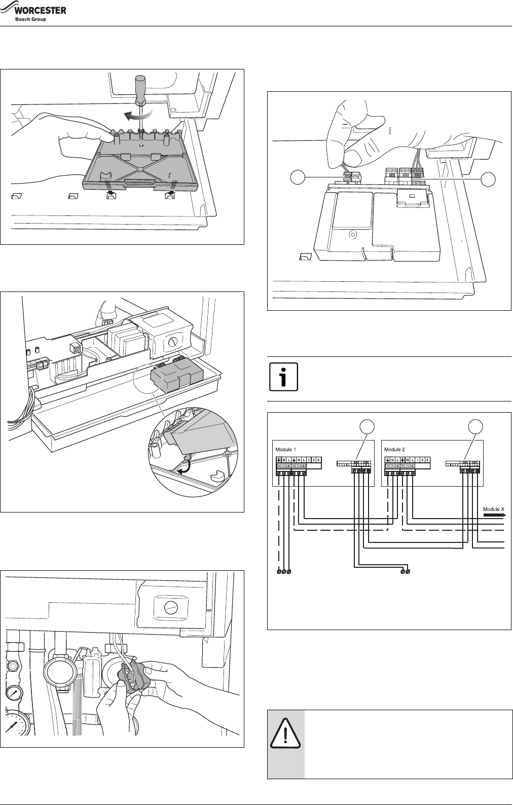
8.5.3Routing the cable through the boiler
▶Route the cable for the low-voltage connections through the hole on
the left [1].
▶Route the cable for the 230 V-connections through the hole on the
right [2].
▶Attach the cable for the 230 V-connections using the strain relief
clamps [3].
Fig. 41Routing the cable
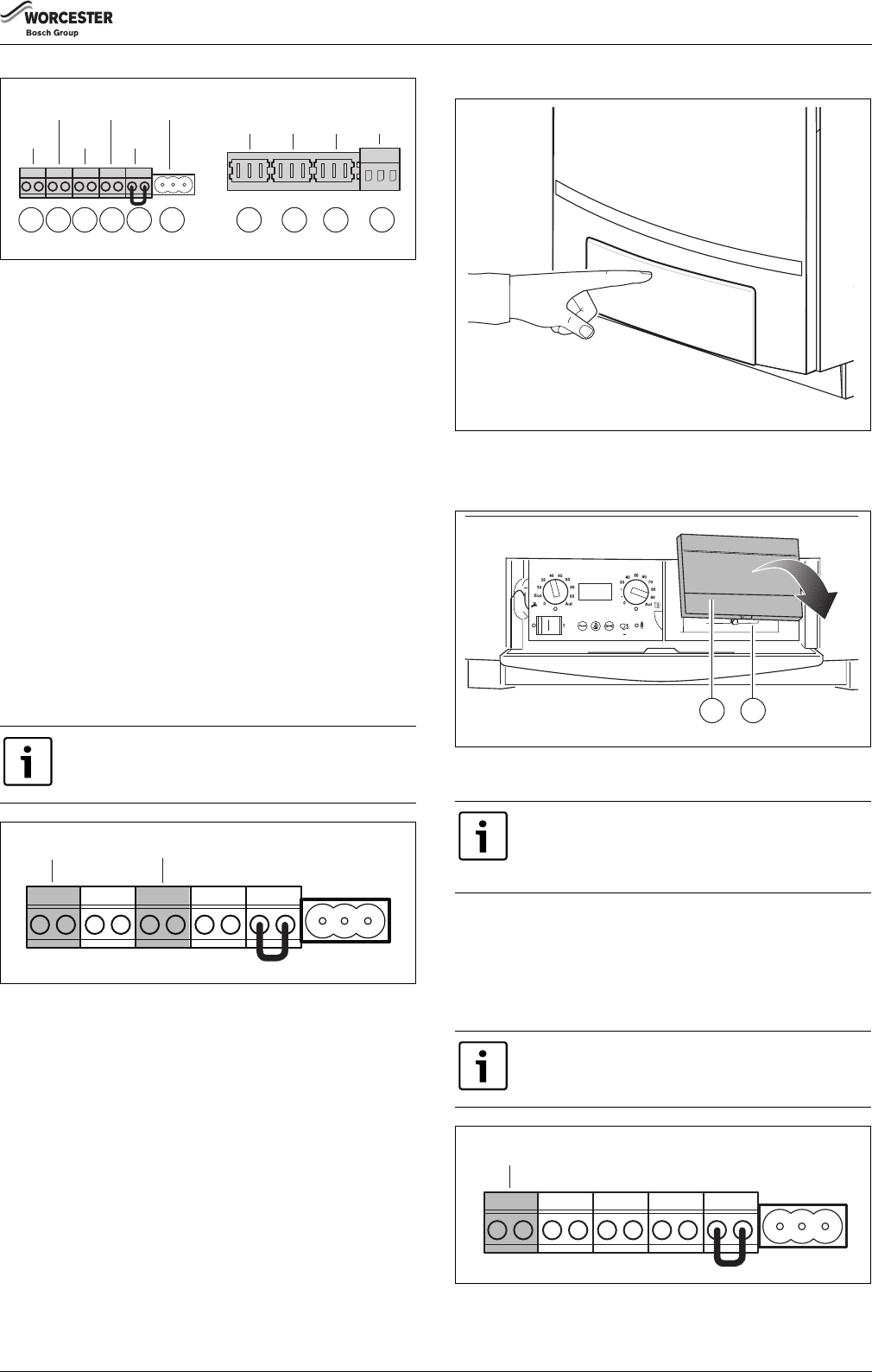
8.5.4Description of the terminal strip connections
▶Connect all components to the relevant terminals.
If uncertain how to connect controls to this appliance,
first contact the Worcester technical helpline on
0330 123 3366 or your supplier.
6 720 648 726-038.1TD
6 720 648 726-039.1TD
DANGER: Danger of fatal accident due to electric shock.
Items 1 – 6 are low-voltage connections and items
7 – 10 are 230 V-connections (fig. 42).
▶Please be aware that there may be a voltage on items
7 – 10 (230 V), when power is supplied to the boiler.
AB
PKPSPZ
Mains
230 V
RCWAEV
FAFWDWV
6 720 648 726-040.1TD
3
2
1
6 720 648 726-041.1TD
Installation
6720813171 (2016/05)27
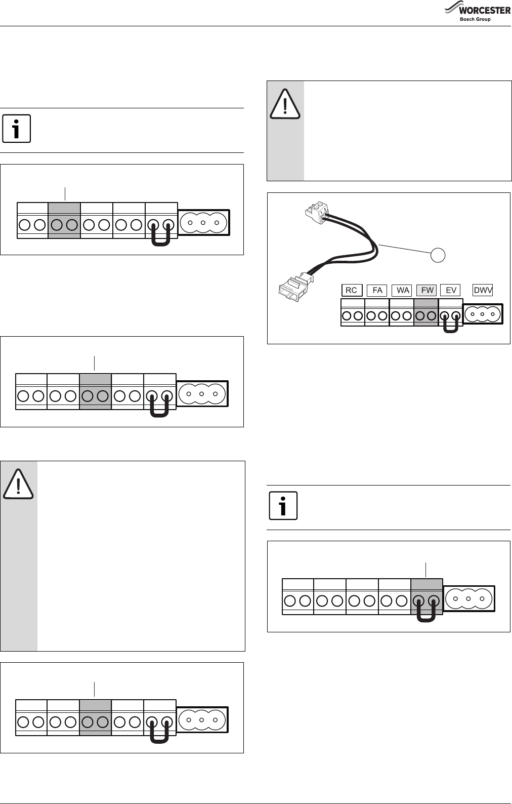
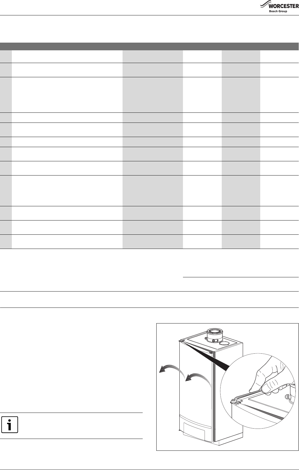
Fig. 42Terminal strip connections
[1]Room controller RC and EMS bus (connection colour orange)
▶Attach the control panel to the boiler door again by following the
above procedure in reverse order and secure it with 2 screws.
e
[a/3/2|
e
[8/0/7|
e
Fault:
The contacts to the heating circuit flow sensor have
shorted or are interrupted, the sensor has been
connected incorrectly or is defective.
NoOffHeating circuit pump 2 is
activated depending on the
preset value. The power to
the mixer is switched off and
the mixer stays in the state it
was last put in (can be
adjusted manually).
e
[a/3/2|
e
[8/1/6|
e
Fault:
MM10 not available or no communication. The heating
circuit addresses on the MM10 and the RC35 do not
match up, the MM10 or the bus circuit is connected
incorrectly or is defective, MM10 is not recognized by the
RC35.
NoOffHeating circuit 2 cannot be
operated correctly. MM10
and the mixer automatically
goes into emergency
operation. Heating circuit
pump 2 is activated
continuously. Monitor data in
the RC35 is invalid.
e
[c/a/\|
e
[2/8/6|
e
Fault:
The return temperature sensor has measured a return
temperature higher than 105 °C.
Yes
5)
6)
7)
8)
flashing
1Hz
No heating operation and no
DHW.
e
[c/u/\|
e
[2/4/0|
e
Fault:
The contacts for the return temperature sensor have
shorted.
Yes
5)
6)
7)
8)
flashing
1Hz
No heating operation and no
DHW.
e
[e/l/\|
e
[2/9/0|
e
Fault:
The UBA 3 or the KIM is defective.
No
4)
5)
OffNo heating operation and no
DHW.
e
[e/\/\|
9)
e
[2/4/2|
–
[2/8/7|
e
Fault:
The UBA 3 or the KIM is defective.
Yes
5)
6)
7)
8)
flashing
1Hz
No heating operation and no
DHW.
[h/\/7|
Operating phase:
The system pressure is too low (less than 1.0 bar).
NoOffPossibly no heating operation
or no DHW available.
e
[h/\/7|
e
Operating phase:
The system pressure is too low (less than 1.0 bar).
NoOffPossibly no heating operation
or no DHW available.
[p/-.-|Operating phase:
The system pressure is too high (over 4.0 bar) or the
pressure sensor has not detected a system pressure
(boiler functioning normally).
NoOff
[\/r/e|Fault:
Reset is carried out. After pressing the “Reset” button this
code is displayed for 5 seconds.
Off
1)Any indication with a permanent dot in the bottom right-hand corner.
2)Only visible on the Service Tool or a specific RC regulator.
3)Any indication with a flashing dot in the bottom right-hand corner.
4)This fault code may deactivate again automatically after a specific time (without reset). Heating and DHW are now available once more.
5)If more faults occur simultaneously, the relevant fault codes are shown after another. If one of these fault codes is a flashing fault code, the other fault codes will also flash.
6)The cause of this fault must be corrected first.
7)The display values, e.g. the system pressure, are also shown as flashing codes.
8)In the event of this fault, the circulation pump is started up and remains in continuous operation in order to minimise the possibility of the heating system freezing up.
9)“E” + random digit or letter.
Display codes
Display code
LED on
UBA 3Other effectsz
Main
display
code
z
Sub
display
code
zKey to display code
Reset
requi-
red?
Table 24Display codes
Technical specifications
6720813171 (2016/05)61
15Technical specifications
The technical specifications serve to provide information about the boiler performance profile.
Libble takes abuse of its services very seriously. We're committed to dealing with such abuse according to the laws in your country of residence. When you submit a report, we'll investigate it and take the appropriate action. We'll get back to you only if we require additional details or have more information to share.
Product:
Forumrules
To achieve meaningful questions, we apply the following rules:
First, read the manual;
Check if your question has been asked previously;
Try to ask your question as clearly as possible;
Did you already try to solve the problem? Please mention this;
Is your problem solved by a visitor then let him/her know in this forum;
To give a response to a question or answer, do not use this form but click on the button 'reply to this question';
Your question will be posted here and emailed to our subscribers. Therefore, avoid filling in personal details.
Register
Register getting emails for Worcester-Bosch GB162-65 at:
new questions and answers
new manuals
You will receive an email to register for one or both of the options.
Get your user manual by e-mail
Enter your email address to receive the manual of Worcester-Bosch GB162-65 in the language / languages: English as an attachment in your email.
The manual is 5,43 mb in size.
You will receive the manual in your email within minutes. If you have not received an email, then probably have entered the wrong email address or your mailbox is too full. In addition, it may be that your ISP may have a maximum size for emails to receive.
If you have not received an email with the manual within fifteen minutes, it may be that you have a entered a wrong email address or that your ISP has set a maximum size to receive email that is smaller than the size of the manual.
The email address you have provided is not correct.
Please check the email address and correct it.
Your question is posted on this page
Would you like to receive an email when new answers and questions are posted? Please enter your email address.