805491
24
Zoom out
Zoom in
Previous page
1/36
Next page
LCD+
User Guide GB
LCD+ solar Controller 3 - 17
Bedienungsanleitung D
LCD+ Solarregler 18 - 35
Controller solare LCD+ 44-53
2
LCD+ LCD solar Controller
Installation and Operation Manual
IMPORTANT!
Before starting work the installer should carefully read this
Installation & Operation Manual, and ensure all instructions are
observed and understood.
The Solar controller should be mounted, operated and
maintained by trained personnel only. Individuals in training are
only allowed to install the product under the supervision of a
qualified installer.
Instructions in this Installation & Operation manual must be
observed when working with the controller. Incorrect operation
shall render the warrenty void. WATTS shall not be liable in the
case of improper usage. Any modifications or alterations are
not allowed for safety reasons. The Solar controller
maintenance may only be performed by service centres
approved by WATTS.
The functionality of the controller is dependant upon the model
and ancillary equipment. This installation leaflet is part of the
product and has to be kept and maintained with the controller.
APPLICATION
The Solar controller is developed for a Solar heating system.
The temperature of the tank water is controlled by temperature
difference “dt” between the solar collector and tank.
The controller is normally used in conjunction with a solar
station which includes a circulation pump and mechanical
pressure Safety valve.
The controller has been designed for use in dry environments,
e.g. in residential rooms, office spaces and industrial facilities.
Verify that the installation complies with local regulations
before operation.
SAFETY INSTRUCTIONS
Before starting work disconnect power supply!
All installation and wiring work related to the controller must be
carried out only when de-energized. The appliance should be
connected and commissioned by qualified personnel only.
Make sure to adhere to local electrical safety regulations.
The controllers are neither splash- nor drip-proof. Therefore,
they must be located in a dry environment.
Do not interchange the connections of the sensors and the
230V connections under any circumstances! Interchanging
these connections may result in life endangering electrical
hazards or the destruction of the unit and other connected
sensors and appliances.
TABLE OF CONTENTS
MAIN CHARACTERISTICS ....................................................... 3
TECHNICAL CHARACTERISTICS ............................................ 3
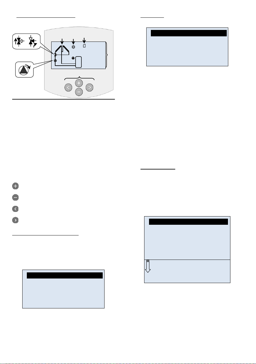
PRESENTATION (Display, keys)............................................... 4
Main menu: 4
1 Quick start menu .................................................... 4
2 Services ................................................................. 5
2.1 Language ............................................................... 5
2.2 Time & Date ........................................................... 5
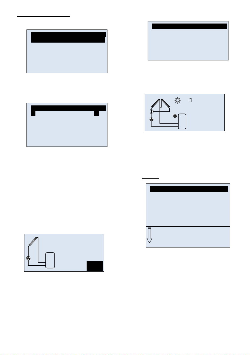
2.3 System ................................................................... 6
2.3.1 System 1 ................................................................ 6
2.3.2 System 2 ................................................................ 6
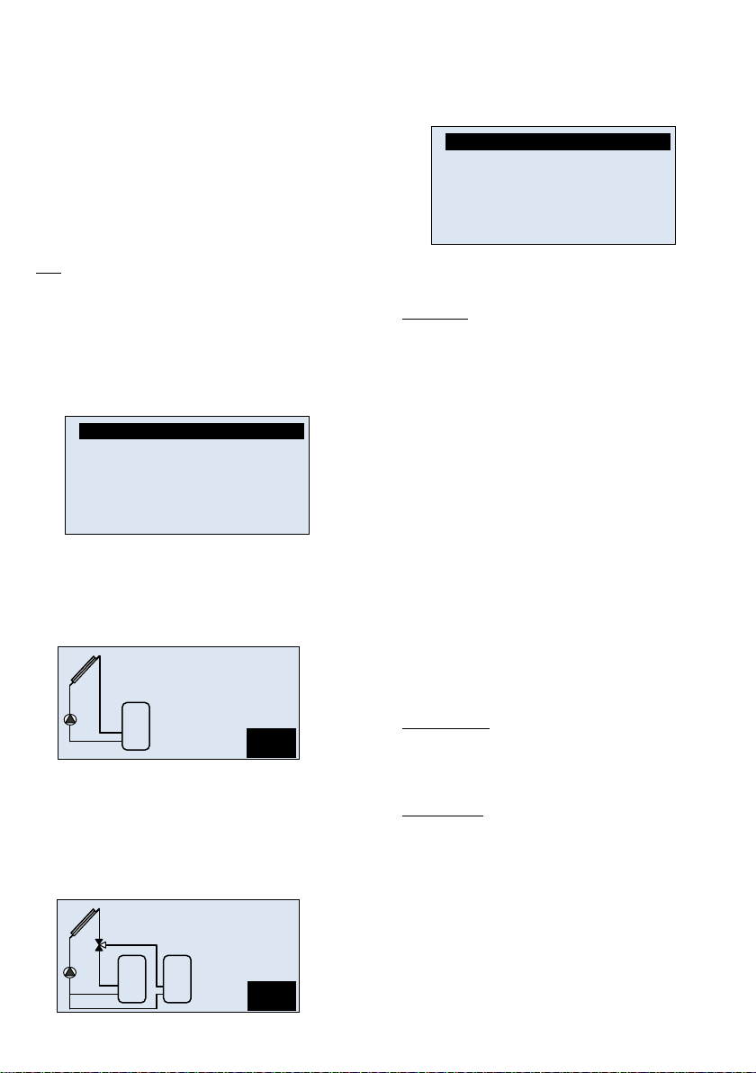
2.3.3 System 3 ................................................................ 7
2.3.4 System 4 ................................................................ 7
2.3.5 System 5 ................................................................ 7
2.3.6 System 6 ................................................................ 7
2.3.7 System 7 ................................................................ 7
2.3.8 System 8 ................................................................ 7
2.4 Outputs configuration ............................................. 8
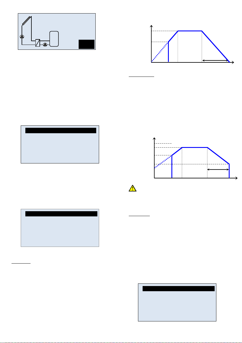
2.4.1 P1 ........................................................................... 8
2.4.2 P2 ........................................................................... 8
2.4.3 Pump P3 ................................................................ 9
2.5 Inputs configuration .............................................. 10
2.5.1 If no flow meter ..................................................... 10
2.5.2 Grundfos sensors ................................................. 11
GDS2 (Grundfos Direct Sensor) .............................................. 11
2.5.3 Impulse Flow meter: ............................................. 11
2.5.4 Temperature Sensor ............................................ 11
2.6 Energy measurment: ............................................ 11
2.6.1 Solar Energy ........................................................ 12
2.6.2 2nd Energy ............................................................ 12
2.7 Protection function ............................................... 13
2.7.1 Max temp collector ............................................... 13
2.7.2 Overheat protection .............................................. 13
2.7.3 Cooling ................................................................. 13
2.7.4 Recooling ............................................................. 13
2.7.5 Freeze protection ................................................. 13
2.8 Degrees................................................................ 13
2.9 Tubes collector ..................................................... 13
2.10 Factory setting ...................................................... 13
3 Settings Menu ...................................................... 13
3.1 Maxtemp tank1 ..................................................... 13
3.2 dTON tank1 .......................................................... 13
3.3 dTOFF tank1 ........................................................ 13
3.4 dTFS: Fullspeed ................................................... 14
3.5 Mintemp collector ................................................. 14
3.6 Maxtemp tank2 ..................................................... 14
3.7 DtON tank2 .......................................................... 14
3.8 dTOFF tank2 ........................................................ 14
3.9 dTON return ......................................................... 14
3.10 dTOFF return ....................................................... 14
3.11 Thermostat Function ............................................ 14
3.11.1 Start...................................................................... 14
3.11.2 Hysteresis ............................................................ 14
3.11.3 Delay .................................................................... 14
3.11.4 Legionella ............................................................. 14
3.11.5 Timer .................................................................... 15
3.12 Cooling Function .................................................. 15
3.12.1 Cooling start ......................................................... 15
3.12.2 Cooling hysteresis ................................................ 15
3.13 Diff control Function ............................................. 15
3.13.1 Max cold tank ....................................................... 15
3.13.2 Min warm tank ...................................................... 15
3.13.3 dTMax .................................................................. 15
3.13.4 dTMin ................................................................... 15
3.14 Antistagnation Function ........................................ 15
3.14.1 Start Level ............................................................ 15
3.14.2 Stop Level ............................................................ 15
4 Operation Menu ................................................... 15
4.1 Automatic and Off operation................................. 15
4.2 Chimney sweep function ...................................... 16
4.3 Manual testing operation: ..................................... 16
5 Operation hours Menu ......................................... 16
5.1 Data logger set with WATTS software and SD
card 16
6 Temperatures Menu ............................................. 17
7 Special Functions ................................................. 17
7.1 Pump exercise function ........................................ 17
7.2 Dimmer function ................................................... 17
7.3 Security function ................................................... 17
8 Others .................................................................. 17
9 Notes .................................................................... 17
3
Menu structure
Service
English “Language”
Time and date
o Time
o Date
o 24/12h clock
o DST
System
o System 1 - 8
o System Parameter (if available)
Outputs Configuration
o P1 “Information of the use”
o P2 “Information of the use”
o P3 “Information of the use”
Inputs Configuration
o Fixed Flowrate value
Flow (l/min)
o Grundfos sensors
GDS1”Sensor choice”
GDS2 ”Sensor choice”
o Impulse flow meter
T6
Liter/Impulse
o Temperature Sensors
T1- T5
Calibration (Pt-1000)
Energy Measurements
o Solar Energy
Adjustments
o 2nd Energy
Adjustments
Protection func.
o Max temp coll.
o Overheat prot.
Overheat temp
o Cooling
Max temp
o Recooling
Min temp
o Freeze prot.
Freeze Temp
Degrees °C/°F
Tube collectors
Factory setting
Quick start menu
o Configuration sequence
Settings
Maxtemp tank1
dT.ON tank1
dT OFF tank1
“Only available with system with 2 tanks”
Maxtemp tank2
dT.ON tank2
dT OFF tank2
“Only available with system 6”
dT.ON return
dT OFF return
dT FS
Mintemp coll.
“Only available if P3 is used as an Extra function”
Extra Function adjustments
Operation
Automatic
Off
Chimney sweep
Manual testing
Operation h
Operation
dT
Power
Energy
SD card
Temperatures
T1
T2
T3
T4
T5
MAIN CHARACTERISTICS
- Large graphic display with backlight
- Easy use interface (4 keys with scroll menu).
- Several languages available
- SD card interface to save the recorded statistics
(Temperatures, Power, Energy, Time operation…) and
parameters.
- 2 energy counters (1 for solar energy and 1 free to specify).
- 1 Bus connection (RJ45) for Extension module (MULTIPLEX)
and communication option.
- Graphic view for Temperature, power, energy…
- 8 working systems with several extra functions possibility
- 5 Inputs for temperature sensors (PT1000 type)
- 1 Logical Input for Impulse flow meter input (for energy
measurement).
- 2 Analogue inputs for Grundfos direct sensors (Flow,
Pressure and temperature sensor)
- 2 electronics outputs for pump (Standard or PWM) with pump
exercise function.
- 1 standard output for Extra function (to control additional
heat, cooling system…)
- Automatic, Off, Manual test mode and chimney sweep
function.
- Sensors Auto checks (Short circuit and breaks)
- Collector protection (Freeze and overheat)
- Permanent memory storage
TECHNICAL CHARACTERISTICS
Operating temperature
0°C 50°C
Electrical Protection
Installation Category
Pollution Degree
IP20
CLASS I
2
Fusible
Power supply
Maximum Power
Consumption
(with all outputs activated)
5AType Fuse 230Vac
(5x20mm)
230Vac +/- 10% 50Hz
4,7A (~ 1080W)
Outputs:
P1 (Main pump with standard
or PWM speed regulation):
P2 (Pump with standard or
PWM speed regulation, valve):
P3 (Extra, Additional heat,
cooling…)
Triac max. 1A 230VAC.
Minimum power switching
>1W
Triac max. 1A 230VAC.
Minimum power switching
>1W
Relay max. 2A 230VAC
* Higher power
consumption: only possible
with external power relay
Inputs:
T1 (Collector1):
T2 (Tank1):
T3 (Extra sensor):
T4 (Extra sensor, Tank2,
Collector2):
T5 (Collector return):
T6 (Flow meter):
GDS1 & GDS2 (Grundfos
sensor):
Flow or pressure.
PT 1000 type
PT 1000 type
PT 1000 type
PT 1000 type
PT 1000 type
Impulse type (low voltage
5V)
Analogue type
(Grundfos VFS, RPS)
Sensors delivered with the
product:
2 Collectors sensor (red)
1 Tank (grey)
1 Extra (grey)
PT1000 (1.5M 180°C)
PT1000 (3M 105°C)
PT1000 (3M 105°C )
Software version
Displayed during
initialisation
Higher Version 11xx
4
PRESENTATION (Display, keys)
1: Simplified drawing of the installation.
- The graphic of the pumps turn when they are
activated.
- The filled triangles on the valve graphic indicate
the circulation
2: Solar loading is in operation.
3: SD card storage is active.
4: Temperature of different sensors, Pumps speed
indications, Power and Energy quantity stored.
A: Keypad description
Navigation key up or plus key (+)
Navigation key down or minus key (-)
Navigation key left (◄)
Navigation key right (►)
Controller information Overview:
An information screen is available to allow you to view quickly
the status of all temperature sensors and outputs connected to
the controller.
From the main display, press (◄) once to display immediately.
The outputs & Inputs screen will be displayed for 1minute,
press (►) at any time to return to the main screen.
Main menu:
First of all press (►) to enter on the navigation menu.
(The title of the active menu is highlighted in black on the top of
the display)
When you enter on the navigation menu you can choose
another submenu by moving the selection cursor with the
keys (+) or (-), then you can enter this submenu with (►).
From all menus you can press (◄) to return to the previous
menu.
*ATTENTION:
As a safety feature, all critical parameters (System and Extra
function) are not programmable 4 hours after power on. If it is
necessary to modify these parameters, you must power-down
and power-up the controller. No settings are lost when
powering-down, or after a power failure.
After 4 hours it is only possible to alter system optimization
settings.
1 Quick start menu
The “Quick start menu” helps you to configure more easily the
main parameters of your solar controller after the initial
installation.
Power-up the controller and wait until the end of the
initialisation sequence. When the main screen is displayed,
press on the key (►) to access to the “service” menu. Then go
to the bottom of the menu and select the line “Quick start
menu” and press the navigation key (►) once to progress to
the quick start configuration.
The controller will guide you through the menu to configure the
main parameters, you will be prompted to adjust the parameter
value by pressing the (+) or (-) input. Press on the (►) key to
validate the display setting and skip to the next parameter.
The controller will return automatically to the main screen when
the configuration process is complete.
1 2
3
T1_ _
_°C
T2_ _
_°C
T3_ _
_°C
T4_ _
_°C
P1_ _ _
%
_ _ _
KW
_ _ _
KWh
T1
T4
T2
T3
A
SD
 Information -
T1 xxx°C T2 xxx°C T3 xxx°C
P1 xxx% P2 xxx% P3 x
 Information -
Services
Settings
Operation
Operation h
Temperatures
 Service -
English
Time and date
System
Outputs Config.
Inputs Config.
Energy Measurements
Protection func.
Degrees °F
Tube collectors No
Factory setting No
Quick Start menu
5
Quick Start menu step by step:
1/ Language choice
- Choose your language with (+) or (-) and press (►) key to
accept.
2/ Time and Date adjustment
- Adjust the hour with (+) or (-) and press (►) key to accept.
- Adjust the minutes and press () key to accept and skip to
the next line.
The controller will skip automatically to the date line, you can
now:
- Adjust the month with (+) or (-) and press (►) key to accept.
- Adjust the day number with (+) or (-) and press (►) key to
accept.
- Adjust the Year with (+) or (-) and press (►) key to accept.
The controller will skip automatically to the clock format line, to
allow you to adjust the time format. Alter with (+) and (-) press
(►) key to accept.
It is possible to select if you require Daylight summer time
advance function with (+) and (-) press (►) key to accept.
3/ System choice
Select the required system with (+) or (-) press (►) key to
accept.
Following system selection, you will be prompted to adjust the
selected system parameters. Proceed to adjust the system
values with (+) or (-) press () key to accept and continue to
the following step in the configuration.
4/ Output configuration
Select the device connected on the output of your controller
(i.e. standard Pump, PWM pump or 3-way valve) with (+) or (-)
press () key to accept and finish the configuration.
N.B.. Depending on the system choice you may be prompted
to configure the P2 output also.
Now your controller is now set-up.
Note:
It is possible to restart the “quick start menu” operation and
follow the steps above to configure again, alternatively it is
possible to directly access a specific parameter throught the
normal menu structure if you have made an error during the
configuration.
2 Services
2.1 Language
- With (+) or (-) select the line “English” and press (►) to
highlight the line.
- Now you can change the language with (+) or (-), you have
the choice between: English, Deutsch, Français, Español,
Italiano, Nederland, Magyarul, and Portugës.
2.2 Time & Date
With (+) or (-) select the line “Time & Date” and press (►)
It is now possible to select the line which requires adjustment
with by pressing (+) or (-), when the correct line is selected
press (►) to highlight the line.
Then use the (+) or (-) to alter the value.
Time,
- Press () once to allow adjustment of the hour.
- Press () for a second time to allow adjustment of
the minutes.
- Depress (◄) twice to return to the line selection.
 Service --- -
English -
Time and date
System
Outputs Config.
Inputs Config.
Energy Measurements
Protection func.
 Time & Date --- -
Time 08:25
Date 02/03/2011
Thursday
24/12H clock 24H
D.S.T. Yes
P1
System
1
T1
T2
T1 _ _ _°C
T2 _ _ _°C
P1 _ _ _ %
 Pump 1 --- -
Type Std Pump
Speed Control Yes
Min rev pump 0%
Max rev pump 100%
T1_ _ _°C
T2_ _ _°C
T3_ _ _°C
T4_ _ _°C
P1_ _ _ %
_ _ _ KW
_ _ _ KWh
T2
T3
SD
T1 T4
 Service -
English
Time and date
System
Outputs Config.
Inputs Config.
Energy Measurements
Protection func.
Degrees °F
Tube collectors No
Factory setting No
Quick Start menu
6
Date,
- Press () once to adjust the Month.
- Press (►) twice to adjustment the Day.
- Press (►) three times to adjustment the the Year.
- Depress (◄) three times to return to the line
selection.
* The day will be automatically displayed.
24H/12H clock,
- Press (►) once to enable the desired choice for
the time format.
D.S.T.
- Daylight Summer Time, activate this function to
enable the automatic hour change between summer
and winter.
Note: If the power supply to the controller is lost the correct
time will be stored in memory for 24H. Longer periods will
require manual readjustment of the clock.
2.3 System
When the line is highlighted, press (►) to enter the
submenu.Choose between the 8 system options, by pressing
(►) key and choose your system with (+) or (-). There is also
the possibility to add different extra functions by using the P3
output (see “output configuration” Chapter 2.4)
2.3.1 System 1
Basic system, with 1 tank, 1 pump, 1 collectors array and 2
sensors.
With this system you can add extra functions with 1 or 2
sensors (Thermostat, Cooling, Antistagnation, Booster or
Diffcontrol function).
The loading of the tank1 is activated if the temperature
difference “dt between the collector (T1) and the tank1 (T2) is
sufficient.
2.3.2 System 2
System with 2 tanks, 1 pump, 1 valve, 1 collectors array and
3 sensors. With this system you can add an extra function
with 1 sensor (Thermostat, Cooling, Antistagnation or
Booster).
The loading of the tanks is activated if the temperature
difference “dt between the collector (T1) and the tanks (T2,
T4) is sufficient.
You will have different adjustments to define the priority of the
tank and also the loading function for the secondary tank.
These following parameters are available for tsytems with
2 tanks.
Priority Tank
No Prio
No priority is done on the tanks. The two tanks are loaded
independently; the only condition is that the “dt” value is
sufficient to initiate tank loading.
1
The primary tank will be the tank1 managed by the sensor T2.
It will be named with a small number “1” in the tank on the
main screen.
2
The primary tank will be the tank2 managed by the sensor T4.
It will be named with a small number “1” in the tank on the
main screen.
If a primary tank is chosen, the loading of this tank will be
made in priority, the secondary tank will be only loaded if:
- The primary tank will reach the “Maxtemp tank(x)” value
adjusted on “setting” menu.
- If the collector temperature is too small to initiate tank
loading of the primary tank. In this case the secondary tank will
be loaded with the cycle function defined by the two following
parameters. This function allows switch back from second tank
to the priority tank.
(1 cycle = “Prio Time break” + “Prio Time charge”)
Note:
All the time if the “dtMax tank(x)” value of the primary tank
becomes sufficient the loading will switch to the primary tank.
Prio Time charge
Load time duration (ON time) for the cycle function.
- To change the duration press (►) to highlight the line and
select your choice with (+) or (-). (Adjustable to 1 to 30min with
default value 15min)
Prio Time break
Break time duration (OFF time) for the cycle function.
- To change the duration press (►) to highlight the line and
select your choice with (+) or (-).(Adjustable to 1 to 30min with
default value 2min)
 System --- -
System 1
P1
System
1
T1
T2
T1 _ _ _°C
T2 _ _ _°C
P1 _ _ _ %
P1
P2
System
2
T1
T1 _ _ _°C
T2 _ _ _°C
T4 _ _ _°C
P1 _ _ _ %
T2 T4
 System --- -
System 2
Prio tank 1
Prio time charge 15m
Prio time break 2m
7
2.3.3 System 3
System with 2 tanks, 2 pumps, 1 collectors array and 3
sensors.
With this system you can add an extra function with 1
sensor (Thermostat, Cooling, Antistagnation).
The loading of the tanks is activated if the temperature
difference “dt between the collector (T1) and the tanks (T2,
T4) is sufficient.
You can choose different possibilities for the priority of the tank
loading. See parts “Priority Tank” for more information.
2.3.4 System 4
System with 1 tank, 1 pump, 1 valve, 2 collector arrays with
2 different cardinal direction (East / West) and 3 sensors.
With this system you can add an extra function with 1
sensor (Thermostat, Cooling, Antistagnation).
The loading of the tank1 is activated if the temperature
difference “dt between collector (T1, T4) and the tank1 (T2) is
sufficient. The valve direction of P2 is achieved by the warmer
of the two collector arrays.
2.3.5 System 5
System with 1 tank, 2 pumps, 2 collector arrays with 2
differents aspects (East / West) and 3 sensors. With this
system you can add an extra function with 1 sensor
(Thermostat, Cooling, Antistagnation).
The loading of the tank1 (T2) is activated if the temperature
difference “dt between the collectors and the tank1 is
sufficient.
The tank will be loaded by the warmer collector (T1 or T4).
P1 // P2
Use this function to authorize the run of the two pumps P1 and
P2 in the same time. (The tank will be loaded by both
collectors)
- To activate the function, press (+) or (-) to select the “P1 //
P2“ line and press (►) to active “yes” this function with (+) or (-
).
2.3.6 System 6
System with 1 collector array, 1 solar tank, 1 pump, 1 valve
and 4 sensors.
With this system you can add an extra function with 1
sensor (Thermostat, Cooling, Antistagnation or Booster).
The loading of the tank1 is activated if the temperature
difference “dt between collector (T1) and the tank1 (T2) is
sufficient.
Heating circuit return pre-heating:
If the "dt" between tank1 (T3) and heating return (T4) is
sufficient, the space heating return will be preheated through
tank1. This saves energy at the external heating source *.
2.3.7 System 7
System with 1 collector array, 1 solar tank, 2 pumps, 1
external heat exchanger.
With this system you can add an extra function with 1
sensor (Thermostat, Cooling, Antistagnation and diffcontrol
function).
The loading of the tank1 is activated if the temperature
difference “dt between collector (T1) and the tank1 (T2) is
sufficient.
Delay P2
You can choose a time delay for the start up of the pump
between the heat exchanger and the tank1. Default value is 1
minutes to give the heat exchanger time to heat up.
- With (+) or (-) select the line “delay P2” and press (►) to put
highlight the line.
- It is now possible to choose the delay for P2 start up with (+)
or (-). (Adjustable 0 to 30 minutes with factory value 1 minute)
2.3.8 System 8
System with 1 tank, 2 pumps, 1 collector array, 3 sensors
and 1 plate heat exchanger. With this system you can add
an extra function with 1 sensor (Thermostat, Cooling,
Antistagnation or booster).
P1 P2
System
3
T1
T1 _ _ _°C
T2 _ _ _°C
T4 _ _ _°C
P1 _ _ _ %
P2 _ _ _ %
T2 T4
P2
P1
T1 _ _ _°C
T2 _ _ _°C
T4 _ _ _°C
P1 _ _ _ %
System
4
T1 T4
T2
P1 P2
System
5
T1 T4
T2
T1 _ _ _°C
T2 _ _ _°C
T4 _ _ _°C
P1 _ _ _ %
P2 _ _ _ %
 System --- -
System 5
P1||P2 No
P2
*
P1
System
6
T1
T1 _ _ _°C
T2 _ _ _°C
T3 _ _ _°C
T4 _ _ _°C
P1 _ _ _ %
T2
T4
T3
P1
P2
System
7
T1
T1 _ _ _°C
T2 _ _ _°C
P1 _ _ _ %
P2 _ _ _ %
T2
 System --- -
System 7
Delay P2 2min
8
Pump-P1 starts if the temperature difference “dt” between the
collector (T1) and tank1 (T2) is sufficient.
The loading of the tank1 with pump P2 is activated if the
temperature difference “dt” between the external plate heat
exchanger (T4) and the tank1 (T2) is sufficient.
The operation of P1 and P2 pumps is totally independent.
2.4 Outputs configuration
- This menu allows configuration of the specific type of output
and the settings of the device connected to all outputs on the
controller. (E.g.High efficiency or standard pump; with or
without speed control, power relay...etc).
There is also the possibility of using the “free” outputs for an
extra function (Thermostat, Cooling, diffcontrol, antistagnation,
booster...)
Note: The outputs “free”, will be marked “not used”
2.4.1 P1
Main pump output, this output is always used to manage the
solar circuit.
There will be the choice between, High efficiency PWM pump,
standard pump or power relay when large pumps are required.
To change the selected pump press (►) to highlight the line
and select your choice with (+) or (-).
PWM Pump
If a PWM pump is connected, there will be the choice between
the 3 main brands, GRUNDFOS, WILO and LAING.
The speed regulation is done by PWM control "ViH = ~11VDC
ViL = <0,5V VDC" with a signal frequency ~ 250Hz”.
Example of compatibility:
- GRUNDFOS SOLAR PM type.
- WILO STRATOS type.
- LAING ECOCIRC E4 PWM1 type.
It is possible to select in percentage form the minimum and
maximum speed of the pump. (Adjustable from 0 to 100%)
The speed of the pump is variable when the value of dt is
between the range “dtFs” and “dtMin”.
dtFS => dT scale of speed variation.
Speed control of the pumps enables the maximisation of the
energy yield from the collectors.
PWM speed regulation explanation:
Standard Pump
If a standard pump is connected, it is possible to control the
speed of the pump; in this case the speed control is done by
pulse packet function.
It is possible to choose in percent form the minimum and
maximum speed of the pump. (Adjustable 30 to 100%)
The speed of the pump is variable when the value of the dt is
between the range “dtFs” and “dtMin”.
This function is an alternative to the High efficiency pump
(PWM), if it is necessary to optimize the efficiency of the solar
installation a PWM high efficiency pump should be utilized.
If the speed control function is not required, selelct “No Sc as
choice.
Pulse packet speed regulation explained
Important Note:
As the speed control is done by pulse packet, noise can occur
in the hydraulic circuit, check the compatibility of the hydraulic
circuit (fitting, pipe…) before selecting this form of speed
control.
Relay / Valve
If it is necessary to connect a large pump for solar installation
with a large collector array (i.e.Pump Power is greater that the
maximum rated output of the controller) , it is possible to drive
an external power relay to control the pump.
Note: no speed control function will be available with this type
of output.
2.4.2 P2
Output P2 is marked “used by system”, it will be possible to
modify its characteristics as described for P1 previously.
If the output is used to manage a direction valve (in System 2
and 4), no choice will be available.To change the type of the
pump press (►) to highlight the line and select your choice
with (+) or (-).
P2
P1
System
8
T1
T1 _ _ _°C
T2 _ _ _°C
T4 _ _ _°C
P1 _ _ _ %
P2 _ _ _ %
T2
T4
 Outputs configuration- -
P1 “Used by system”
P2 “not used”
P3 “not used”
 Pump 1 --- -
Type PWM Pump
Speed Control Grundsos
Min rev pump 0%
Max rev pump 100%
dTOF
F
dTON
Max rev pump
Pump startup
Min rev pump
dTFs
dTFs
Controlled
Speed range
0%
Pump startup
Min rev pump
dTOFF
dTON
Max rev pump
Min rev pump
dTFs
dTFs
Controlled
Speed range
30%
100%
 Pump 2 --- -
P2 “Used in system”
Type Std Pump
Speed Control no
9
If the output is “not used” there is the possibility to use the
output as a booster pump of the main pump P1 with System 1.
This function is useful when utilizing a “drain back system” to
enable the primary pump P1 to initiate the circulation of the
heat transfer fluid.
In this instance pump P2 is normally installed in series with the
main pump P1.
- You could choose the duration for the running time of P2 with
(+) or (-). (Adjustable 1 to 10 minutes)
Booster function explanation:
Exemple:
2.4.3 Pump P3
P3 is a supplementary output which can be used for an
additional extra function and is generally used in combination
with the solar system or totally independent. There will be a
choice between the different functions depending upon the
selected system configuration selected.
2.4.3.1 Thermostat Heating Function
With an additional sensor (T3) this function is used for
secondary heat source pump (P3) control.
Suggestions:
- Pump controls for Fuel or Gas burner…
- Immersion Electrical Heater inside the solar tank.
Important: In this instance an external power relay must be
connected for the switching of the output load!
Example:
All adjustable settings available for this function are accessible
in the Settings menu; see section “Settings” chapter 2 for a
further explanation of the functions.
2.4.3.2 Thermostat Cooling Function
With an additional sensor (T3) this function is used for
cooling of the solar tank with an external heat sink
Suggestions:
Charging a swimming pool.
Example:
All adjustable settings available for this function are accessible
in the Settings menu; see section “Settings” chapter 2 for a
further explanation of the functions.
2.4.3.3 Diffcontrol Function
With additional sensors (Tcold=T3, Twarm=T4) this function
is used for secondary heat source pump control or charging
a tank.
The loading of the Tcold=T3 is activated if the temperature
difference “dt” between the Twarm=T4 and the Tcold=T3 is
sufficient.
Example 1:
 Pump 2 --- -
P2 Booster
Boost Duration 2min
Tank1
T2 C)
dTMin
dTMax
P1
Collector
T1 C)
Maxtemp
Tank1
dTMax
dT = T1
T2
100%
0%
dTMax
Boost time
P2
T1
P1
T2
Extra Function to control a
second pump in serie with P1
to help the liquid circulation
startupthe pump coupled with
an external burner.
P2
Heat Source
T1
P3
P1
T3
T2
Extra Function to control
the pump coupled with
an external burner.
Heat
sink
T1
P
3
P
1
T
3
T2
Extra Function used to control the pump to
warm up another tank or basin
P3
P1
T2
Extra Function used to control
the pump (P3) to warm up
"Tcold=T3", if the temperature
difference (dt) to "Twarm=T4"
is sufficient.
T1
TC = T3
TW = T4
10
Example 2:
All adjustable settings available for this function are accessible
in the Settings menu; see section “Settings” chapter 2 for a
further explanation of the functions.
2.4.3.4 Booster Function
See the previous part P2 for more explanation of this function.
Exemple:
2.4.3.5 Antistagnation Function
The antistagnation function is used in combination with the
Watts
anti-stagnation unit. At times of excessive solar radiation the
solar fluid is protected from stagnation, where otherwise the
heat transfer fluid would vaporize.
If the solar circuit (T1, T4 (when two collector fields)) is heated
to 110°C (default value, can be changed), the relay output P3
and solar circuit P1 are switched ON. P3 is connected with the
3-way valve and fan of the Watts antistagnation unit.
After the solar circuit is cooled down to 90°C (default value,
can be changed), the outputs P3 and P1 are switched off.
Example 1:
Example 2:
All settings adjustment available for this function will be
accessible in the Settings menu, see parts “Settings” chapter 2
for more explanation of the function and possibilities.
2.5 Inputs configuration
- It is possible to configure and monitor all inputs available on
the controller. (Digital or analog inputs)
2.5.1 If no flow meter
Estimated flow input
If no impulse flow meter is installed (factory setting) the flow
must be entered, which can be seen on the flow-meter in the
solarstation.
The flow reading from the glass-scale at the flow-meter can be
entered by marking the value line with (>) and adjusting the
flow-setting with (+) or (-). (Adjustable 1 to 100 L/min with
factory value 10 L/min)
Important Note:
The flow must be read when the pump is running at 100%
speed.
Other heating system
with tank. (Fuel, pellets,
wood ….)
P
3
P
1
TC =
T3
T2
Extra Function used to control the
pump (P3) to warm up "Tcold=T3", if
the temperature difference (dt) to
"Twarm=T4" is sufficient.
T1
TW =
T4
T1
P1
T2
Extra Function to control a
second pump in serie with P1
to help the liquid circulation
startupthe pump coupled with
an external burner.
P3
P3
P1
T2
Extra Function used to cool down the solar circuit
with the TISUN antistagnation units.
T1
P3
P1
T2
Extra Function used to discharge the collector in
another free heat storage or under ground
discharge loop...
T1
 Inputs configuration -
If no flow sensor
Flow (L/min) 10
Grundfos sensors
GDS1
GDS2
Impuls flow meter
T6
Temperature sensor
T1 xxx°C
T2 xxx°C
T3 not used
T4 not used
T5 not used
* In this case the output P3 will need the
power relay “LR 20 3S”installed.
11
2.5.2 Grundfos sensors
- Your controller had 2 specials inputs for analogics sensors
GRUNDFOS (Type VFS Flow sensor or RPS pressure
sensor).
The Flow sensor is used for energy measuring and
supervision, the pressure sensor is used only to supervise the
pressure on the primary circuit.
GDS1 (Grundfos Direct Sensor)
Once the line selected press (►) to enter in the submenu
GDS1.
You will have the choice between Flow or Pressure sensor with
different scales.
To choose the type of the sensor connected press (►) to
highlight the line and select your choice with (+) or (-).
- NC Not used
- RPS 0 4 bar Pressure sensor
- RPS 0 6 bar Pressure sensor
- RPS 0 10 bar Pressure sensor
- VFS 1 12l/min Flow sensor
- VFS 2 40l/min Flow sensor
- VFS 5 100l/min Flow sensor
- VFS 10 200l/min Flow sensor
- VFS 20 400l/min Flow sensor
Sensor type: see type plate on the mounted sensor
- Following your sensor choice you can view the
instantaneous values of the temperature, flow or pressure
measured by the sensor.
With Flow sensensor “VFS”,
With Flow sensensor “RPS”,
GDS2 (Grundfos Direct Sensor)
This input has the same function and possibilities of the GDS1
input,
2.5.3 Impulse Flow meter:
If impulse flow meter is installed (on T6 / PF) select “Yes”, then
you must enter with (+) or (-) the flow meter characteristics in
liter / Impulse.
(Adjustable 1 to 25 L/imp with factory value 10 L/imp)
When you use an impulse flow meter for energy measuring,
you must
Connect a temperature sensor (usually T5) mounted on the
collector return piping, to get the correct calculated energy
values.
Important Note:
You must not connect an impulse flow meter to T6, if a digital
pressure or flow sensor is connected to GDS2!
2.5.4 Temperature Sensor
This submenu allows viewing of the current state of all
temperature sensors connected on the controller; you can
immediately see the actual value measured by the sensor, if it
is in use or not & if the sensor is defective.
By pressing on the on the (►) key, you will acced the
calibration of the sensor.
Careful: Check the real value of the sensors with calibrated
thermometer before adjusting. (Calibration range -3 to +3°C
with factory value 0°C)
2.6 Energy measurment:
The controller has two energy measurement blocks. It is
possible to configure for both blocks the sensors which will be
used for energy calculation.
Energy metering calculation logic:
To calculate the energy the controller needs several elements,
two temperature measurement points “Warm” and “Cold”, the
flow value and the heat transfer fluid properties.
 GDS1---- --- -
GDS1 NC
 GDS1---- --- -
GDS1 VFS 1-12 l/min
Flow x.x l/min
Temp GDS1 xxx°C
 GDS1---- --- -
GDS1 RPS 0 - 4 bar
Pressure x.x bar
Temp GDS1 xxx°C
 T6 --- -
Impulse flow meter no
 T6 --- -
Impulse flow meter Yes
Liter/impulse 10
 Inputs Configuration---- -
Temperature sensors
T1 xxx°C
T2 xxx°C
T3 xxx°C
T4 not used
T5 not used
 T1 --- -
Pt1000
Calibration 0°C
12
2.6.1 Solar Energy
This first block is reserved to calculate the solar energy; it is
possible to select the sensors used for the calculation.
To change a selected sensor, press (►) to highlight the line
and select the choice with (+) or (-) according the
installation.
Flow sensor
- Auto
The controller will use the theorical flow (liter/min) entered in
the “Inputs configuration” if no flow meter is available.
- T6
The controller will use the impulse meter connected on the
input “T6”.
- GDS1
The controller will use the Grundfos vortex sensor “VFS type” if
connected to the GSDS1 input.
Hot sensor
- Auto
The controller will automatically choose the corresponding hot
sensor according to the system selected (T1 or T4 collector
sensors).
- T1” or “T4
The controller will use the PT1000 sensor T1 or T4 according
to the user selected sensor.
- GDS1
The controller will use the temperature sensing element of the
Grundfos vortex sensor “VFS type”.
Cold sensor
- Auto
The controller will automatically choose the corresponding tank
sensor according to the system selected (T2 or T4 tank
sensors).
- T5
The controller will use the PT1000 sensor T5.
- GDS1
The controller will use the temperature sensing element of the
Grundfos vortex sensor “VFS type”.
Note: Do not choose the same sensor for “Hot” and
“Cold”, The energy calculation will be incorrect.
Fluid
- Water
The controller will use the heat transfer coefficient of water for
the calculation.
- Glycol
The controller will use the Water-Glycol coefficient according to
the percent of glycol selected for the calculation.
Mixing parameter: adjustable from 10% to 50% of Glycol mixed
in the fluid.
Flow (Volume)
- View of the cumulated volume in m3.
It is possible to reset the stored value by holding down on the
(►) & (-) keys for 5 sec.
Energy
- View of the cumulated energy in kWH.
It is possible to reset the stored value by holding down on the
(►) & (-) keys for 5 sec.
Power
- View of the instantaneous power in W.
2.6.2 2nd Energy
The second energy block can be used to calculate or
supervise another circuit, this circuit can be totaly
independant of the solar circuit, (energy supplied by the
additional heat boiler, energy used for D.H.W. etc.).
If it is necessary to use this block, select “Yes” on the “2nd
Energy” line.
The functionality is identical to the above explained 1st
block.
Flow sensor
- Auto
The controller will use the theorical flow (liter/min) entered in
the “Inputs configuration” if no flow meter is available.
- T6
The controller will use the impulse meter connected on the
input “T6”.
- GDS2
The controller will use the Grundfos vortex sensor “VFS type” if
connected to the GDS2 input.
Hot sensor
- T1” to“T5
The controller will use the PT1000 sensor T1 toT5 according to
the user selected sensor.
- GDS2
The controller will use the temperature sensing element of the
Grundfos vortex sensor “VFS type”.
Cold sensor
- “T1” to“T5
The controller will use the PT1000 sensor T5 according to the
user selected sensor.
- GDS2
The controller will use the temperature sensing element of the
Grundfos vortex sensor “VFS type”.
Note: Do not choose the same sensor for “Hot” and
“Cold”, The energy calculation will be incorrect.
Fluid
- Water
The controller will use the heat transfer coefficient of water for
the calculation.
- Glycol
The controller will use the Water-Glycol coefficient according to
the percent of glycol selected for the calculation.
Mixing parameter: adjustable from 10% to 50% of Glycol mixed
in the fluid.
Warm point
P1
Function use for solar
calculation of energy
return.
Cold point Flow meter
 Energy measurement -
Flow sensor Auto
Hot sensor Auto
Cold sensor Auto
Fluid Glycol
Mixed 40%
Flow (Volume) xxxxm3
Energy 0kWh
Power 0.0kW
 2nd Energy -
2nd Energy Yes
Flow sensor Auto
Hot sensor Auto
Cold sensor Auto
Fluid Glycol
Mixed 40%
Flow (Volume) xxxxm3
Energy 0kWh
Power 0.0kW
13
Flow (Volume)
- View of the cumulated volume in m3.
It is possible to reset the stored value by holding down on the
(►) & (-) keys for 5 sec.
Energy
- View of the cumulated energy in kWH.
It is possible to reset the stored value by holding down on the
(►) & (-) keys for 5 sec.
Power
- View of the instantaneous power in W.
2.7 Protection function
With this menu it is possible to select and adjust all the
protective functions and parameters of your installation.
2.7.1 Max temp collector
- Setting the start level of the overheat protection for the
collector array.
(Adjustable 110 to 150°C with factory value 120°C)
2.7.2 Overheat protection
This function will stop all collector circulation (P1 and P2) when
the collector temperature increases above “Maxtemp” plus an
offset value (+10°C default value, can be changed). This
function is used to protect the elements of the installation
(Pipe, fitting, ring rubber...)
- To activate the function, press (+) or (-) to select the
Overheat prot.“ line and press (►) to active “yes” this
function with (+) or (-).
- It is now possible to adjust the offset level
(Adjustable +10°C to +30°C with factory value +10°C)
IMPORTANT: For safety reasons this function should
always be “Yes
2.7.3 Cooling
- When the “cooling” function is active “Yes”, it is also possible
to activate the “Recooling” function.
This option is used to protect the collector heat transfer fluid
and system as follows; it activates the solar pump P1 or P2 if
temperature of the collector arrays T1 or T4 exceeds the “Max
temp coll.” value even if the set maximum temperature in the
tank is exceeded.
The circulation stops when:
- Temperature in the collector has dropped 10°C.
- Temperature in the tank reaches the cooling “Max Temp
level (MaxTemp Tankx + xx°C) adjustable 5°C to +40°C with
default value of +10°C.
- If the water temperature in the tank reaches 95°C.
2.7.4 Recooling
When the water temperature inside the tank is above the
setting level “Maxtemp tank X” and the collector temperature is
10°C under the pump is activated to cool the tank through the
collector array (during the night).
The pump will be turned off when:
- The water temperature inside the tank has dropped to the
setting level recooling “MinTemp”“(MinTemp Tankx - xx°C)
adjustable -5°C to -40°C with default value -10°C.
- When the difference between the tank and collector array
temperature is below 2°C.
2.7.5 Freeze protection
This option will keep the solar panel temperature T1 or T4
above the Freeze setting level (see below) by activating the
pump P1 or P2.
This option can be used to reduce snow accumulation on the
panel and increase the efficiency during the day or to avoid
damage by the freezing and expansion of the heat transfer
fluid.
Careful: it is preferable not to use this function in very cold
regions in order not to use too much the energy stored in the
tank
- To activate the freeze and snow protection, press (+) or (-) to
select the “Freeze prot“ line and press (►) to active “yes” this
function with (+) or (-).
- It is now possible to adjust the Freeze setting level
(Adjustable -20°C to + 7°C with factory value 3°C)
2.8 Degrees
- On this menu you can choose the displayed units.
°F: °F, 12H am/pm, Liter, KW and KWh
°C: ° C, 24H, Liter, KW and KWh
2.9 Tubes collector
Select the lines “Tubes collector” and press (►) to highlight
the line.
- Now select with (+) or (-) yes” if your installation use vacuum
tubes collector. (This choice can be use with flat collector when
the sensor is mounted on the external parts of the collector).
- This function could be used if the collector sensor is not
directly mounted on the collector.
This function works in the following way.
Each 30 minutes the pump will be activated 30 seconds to
measure the correct value on the collector to avoid short
charge cycle.
2.10 Factory setting
Important: For reasons of error protection the selected system
and time settings will not be reset!
- If you want to reload all parameters with factory value select
press (►) to highlight the line. Then select “yes” with (+) key.
- Now press (◄) repeatedly to return to the main menu.
3 Settings Menu
On this menu you have all basic adjustable settings of your
installation.
3.1 Maxtemp tank1
- Maximum value of desired water temperature on the tank1
during normal operation. (Adjustable 15 to 95°C with factory
value 65°C)
3.2 dTON tank1
- Difference between collector temperature T1 and Tank1
temperature T2 to start the main pump1. (Adjustable 4 to 40°C
with factory value 15°C)
3.3 dTOFF tank1
- Difference between collector temperature T1 and Tank1
temperature T2 to stop the main pump1. (Adjustable 2°C bis
35°C (dTMin <=2°C dTMax Tank 1 with factory value 7°C)
 Protection Function -
Max temp coll. 120°C
Overheat prot. Yes
Overheat temp. +10°C
Cooling Yes
Max temp (xx°C) +40°C
Recooling Yes
Min temp (xx°C) -40°C
Freeze prot. Yes
Freeze prot. Temp. -20°C
14
3.4 dTFS: Fullspeed
- Difference between collector temperature T1 and Tank1
temperature T2 to have the full speed (100%) on the pump.
(Adjustable between minimum "dTMax tank1" and maximum
50°C (default value 35°C))
3.5 Mintemp collector
- This setting level is used to define a minimum temperature on
the collector to authorize the solar loading. (Adjustable
between 0°C and 99°C.(default value 25°C))
The following settings are only available with two tanks (2 and
3).
3.6 Maxtemp tank2
- Maximum value of desired water temperature on the tank2.
(Adjustable 15 to 95°C with factory value 65°C)
3.7 DtON tank2
- Difference between collector temperature T1 and Tank2
temperature T4 to start the main pump1 with system2 or
pump2 with system3.
(Adjustable 3 to 40°C with factory value 15°C)
3.8 dTOFF tank2
- Difference between collector temperature T1 and Tank2
temperature T4 to stop the main pump1 with system2 or
pump2 with system3. (Adjustable 2°C bis 35°C (dTMin <=2°C
dTMax Tank 2) with factory value 7°C)
Note:
With a system with two tanks the priority tank can be chosen in
the “Service menu in submenu “System”, and also choose
the time of the loading cycle for the secondary tank in
submenus “Prio tank load” and “Prio tank break”.
The following settings are only available with system 6.
3.9 dTON return
- Difference between Tank1 temperature T2 and external
space heating return T4 to start the preheating of this external
space heating return throuhgh tank1. (Adjustable between 3 to
40°C (default value 15°C))
3.10 dTOFF return
Available only with the system 6
- Difference between Tank1 temperature T2 and external
space heating return T4 to stop the preheating of the external
circuit. (Adjustable 2 to (dTMax return -2°C) with factory value
7°C)
EXTRA FUNCTIONS SETTINGS ADJUSTMENT
The Extra adjustments will be only available if one Extra
function is chosen on an output in the “output configuration”
menu.
3.11 Thermostat Function
Available only if extra function “thermostat” is selected on the
output P3
3.11.1 Start
- setting level to start the additional heat (P3) when the
water temperature on the top of tank (T3) decreases under
this setting level.
(Adjustable 20 to 90°C with factory value 55°C)
3.11.2 Hysteresis
- Value of the hysteresis to stop the additional heat (P3)
when the water temperature on the top of tank (T3) is more
than the start temperature plus the hysteresis value.
(Adjustable 2 to 30°C with factory value 10°C)
The following Timer parameters are available for the
following extra functions, “Thermostat”, “Cooling” &
“Diffcontrol”.
3.11.3 Delay
- Time delay to start the output (P3).
If adjusted on minus value “-xxxs”, the relay P3 will start “xxx
seconds” before the startup demand.
If adjusted on plus value “+xxxs”, the relay P3 will stop “xxx
seconds” after the stop demand.
(Adjustable -900s to +900s with default value “0”)
3.11.4 Legionella
- The Number of days to activate the legionellosis function.
This function is generally used when the tank is filled with
D.H.W., it heats with the extra output (P3) the tank up to
65°C (T3) if the water inside the tank did not reach this level
during the previous number of days selected. (Adjustable 1
to 7 days with factory value 1).
Water temperature on top of tank1 T3 (°C)
T3 start
T3 start +
hysteresis
Extra P3
Tank1
T2 F)
dtMin
dt Fs
P
1
Collector
T1 F)
Maxtemp
Tank1
dt Fs
dT = T1
T2
100
%
0%
dtMax
Control
dtMax
85%
OFF
100%
Control
100%
100%
OFF
15
3.11.5 Timer
- The timer block is used to cretate a daily program to
initialise the operation time of the extra output (P3), this
function is generally use for energy saving in the case of an
additional heat source being used to warm the tank (e.g.:
additional heat is present only at the end of the day if the
sun loading was insufficient during the day.)
To use the Timer function select the line “Timer” and choose
“Yes”, then there is the possibility of adjusting the “start” and
“stop” times for three blocks.
3.12 Cooling Function
Available only if extra function “coolingis selected on the
output P3
3.12.1 Cooling start
- setting level to start cooling the tank1 (by activating P3
output) to another heat storage for example when the water
temperature in the top of tank1 (T3) is above this setting
level. (Adjustable 20 to 90°C with factory value 75°C)
3.12.2 Cooling hysteresis
- Value of the hysteresis to stop cooling the tank1 when the
water temperature on the top of tank (T3) is under Cooling
start temperature minus hysteresis value. (Adjustable 1 to
30°C with factory value 10°C)
3.13 Diff control Function
Available only if extra function “diff controlis selected on the
output P3.
3.13.1 Max cold tank
- Maximum level on tank1 to stop the exchange function (T3
= TC).
(Adjustable 15 to 95°C with factory value 65°C)
3.13.2 Min warm tank
- Minimum level on external tank to start the exchange
function (T4 = TW). (Adjustable 0 to 95°C with factory value
15°C)
3.13.3 dTMax
- Value of the difference between cold and warm storage to
start the exchange function. (Adjustable 3 to 40°C with
factory value 15°C)
3.13.4 dTMin
- Value of the difference between cold and warm storage to
stop the exchange function. (Adjustable 2 to 30°C with
factory value 7°C)
3.14 Antistagnation Function
Available only if extra function “Antistagnationis selected on
the output P3.
3.14.1 Start Level
- Setting level on collector (T1) to start the function, the
pump P1 will be turned on to discharge the warm
temperature of the collector through the relay P3.
(Adjustable 0 to 200°C with factory value 110°C)
3.14.2 Stop Level
- Setting level on collector (T1) to stop the antistagnation
function, the pumps P1 and P3 will be turned off. (Adjustable
0 to 150°C with factory value 90°C)
4 Operation Menu
4.1 Automatic and Off operation
- To put your system in Automatic operation, press (+) or (-) to
select the “Automatic“ line and press (►) to active this
working mode.
- To put your system in Off mode repeat the same sequence
as above.
Note: The controller status is displayed by a small graphic, on
the main screen stating “OFF”
 Settings -
Delay +900s
Timer On
Time 1 Start 24H00
Time 1 Stop 24H00
Time 2 Start 24H00
Time 2 Stop 24H00
Time 3 Start 24H00
Time 3 Stop 24H00
Water temperature on top of tank1 T3
C)
Cooling stop
(start hysteresis)
Cooling
start
P3
Warm storage TW
Cold storage TC
MinWarm
tank
MaxCold
Tank
Extra
P3
dTMin
dTMax
Collector
(T1°C)
Stop level
Start level
P1
Tank (T2°C)
P3
Standard
loading cycle
Antistagnation
cycle
 Operation--------------- -- -----
Automatic (Active)
OFF
Chimney sweep
Manual testing
16
4.2 Chimney sweep function
WARNING USE AT OWN RISK:
The space heating is set up to maximum temperature to
prevent the burner from overheating. Some heating pipes
can be damaged at temperatures over 40°C!
The “chimney sweep” function is used for:
exhaust fume measurements at the heating system
to put maximum heating load on the system
(burn possible deposits in the burner, when run for
extended periods at partial load)
Attention safety rules when using the “chimney sweep
function:
1. Chimney sweep” function is activated for the time it is
needed.
During the Chimney sweep function the outputs:
P3, (with MULTIPLEX P4, P5, P7, P9, P10) will be turned
ON
P1, P2, (With MULTIPLEX P6, P8) will be turned OFF
WARNING: don’t overheat your system!
2. When the “Chimney sweep” is finished, Switch Off the
LCD+ controller for a few seconds. Off (active)
3. Before restarting the LCD+ controller check all elements
(pipes…) of the installation to be ensure that no damages
has occured,
Automatic (active)
4.3 Manual testing operation:
- In this mode it is possible to check the operation of Pump1,
Pump2/Valve and extra outputs. It is also possible to check the
values of all sensors inputs.
N.B. the sensor input not used are noted with the maximum
value.
- To activate the output select the desired line with (+) or (-)
and press (►) to highlight this line. Now with (+) or (-)the
different outputs can be tested.
- The pump activation starts with the minimum value xx%
adjusted on the “Setting” menu (see Pump speed) and can be
increased from 5% up to 100% in steps with (+) key.
Note: When you exit this menu all outputs are turned off.
- Press (◄) repeatedly to return to the main menu.
5 Operation hours Menu
In this menu it is possible to observe the cumulative totals for
operating hours, dT, power and energy input registered by the
controller.
The controller has the ability to record and store all data and
parameters of the installation on an SD card. This enables the
analysis of the efficiency of the solar installation and also
allows the pre-configuration of the installation parameters on
your computer. (This functions require a special Watts Data
Logger Kit with software. Watts order number P04189)
After the SD card is inserted, it must be activated:
Select the SD card line with (+) or (-) and press (►) to highlight
this line. Now with (+) or (-) you can activate or deactivate the
SD card.
SD card Deactivate => the SD card is ready to work
SD card Activate => the SD card is off or deactivated
Attention:
- The recording of the data on the SD card is only possible if
the SD card is inserted and activated. (All data already
registered by the solar controller before will not be recorded
on the computer)
- A small SD card logo on the main screen is visible if the SD
card is inserted and activated.
Important: Do not unplug the SD card before deactivate it.
5.1 Data logger set with WATTS software and SD
card
The controller has the ability to record and store all data and
parameters of the installation on an SD card. This enables the
analysis of the efficiency of the solar installation and also
allows the pre-configuration of the installation parameters on
your computer. (This functions require a special Watts Data
Logger Kit with software. Watts order number P04189)
a) Systems and parameters for the installation
(Schemes, extra functions, speed control, priority tank, flow
sensor …)
- Set the parameters for the system on the computer and
transfer the data to the controller
- Analyze the recorded parameters from the SD card on
the computer
This requires hardware and software: SD card set
- Record the current operation data from the solar system
on the SD card
This requires hardware and software: SD card set; SD card
max. 2GB, no SDHC
b) Operation data; system control and measuring of
energy
(The data of the system can be recorded, as energy,
operation hours, temperatures of the sensors, pump speed and
priority time break, flow …)
- Record permanently the operation data on the SD card
Requires Hard and Software: SD card set
- Analyze of the operation data; system control and
measuring of energy on a PC
Requires Hard and Software: SD card set
Attention::
For the following functions the special Watts Data Logger
Kit no. P04189 is required
- Set the parameters for the system on your computer and
transfer the data to the controller
- Analyze the recorded parameters from the SD card on the
computer
- Analyze of the operation data; system control and
measuring of energy on the PC
For the following functions there is no special Watts Data
Logger Kit required
(For this function only an empty SD card is required. Not
included in the controller)
- Recording permanently the Operation data on the SD card
- Recording the current operation data from the controller on
the SD card.
 Manual testing------------- --
P1 0%
P2 0%
P3 0
T1 _ _ °C T2 _ _°C T3 _ _ °C
T4_ _°C T5 _ _ °C
GT _ °C F _ _ L/min P _ _ Bar
 Operation h------------ -- --- --
Operation _ _ h
dT _ _°C
Power _ _kW
Energy _ _kWh
SD card Deactivated
24
2.3.6 System 6
System bestehend aus: 1 Kollektorfeld, 1 Speicher, 1 Pumpe,
1 Ventil und 4 Sensoren.
In diesem System kann noch eine Funktion mit 1 Sensor
hinzugefügt werden (Thermostat, Kühlung, Antistagnation).
Der Speicher1 wird beladen, wenn die Temperaturdifferenz
dt“ zwischen Kollektor (T1) und Speicher1 (T2) erreicht wird.
Vorwärmen Heizkreisrücklauf:
Wenn die Temperaturdifferenz „dt“ zwischen Speicher1 (T3)
und Rücklauftemperatur (T4) erreicht wird, erfolgt das
Vorwärmen des Heizungsrücklaufs über Speicher1. Dies spart
Energie auf der Seite des externen Heizsystems*.
2.3.7 System 7
System bestehend aus: 1 Kollektorfeld ,1 Speicher, 2 Pumpen
1 externer Plattenwärmetauscher.
In diesem System kann noch eine Funktion mit 1 Sensor
hinzugefügt werden (Thermostat, Kühlung, Antistagnation und
Differenzreglung).
Der Speicher1 wird beladen, wenn die Temperaturdifferenz
dt“ zwischen Kollektor (T1) und Speicher1 (T2) erreicht wird.
Die Zeitverzögerung für das Einschalten der Pumpe zwischen
Plattenwärmetauscher und Speicher1 kann ausgewählt
werden. Der Standardwert ist 1 Minute. Dies gibt dem
Plattenwärmetauscher Zeit zum Warmlaufen.
Verzögerung (Delay) P2
Steht nur für System 7 zur Verfügung.
- Zeitverzögerung für das Einschalten der Pumpe P2, nachdem
Pumpe P1 gestartet ist.
- Mit den Tasten (+) oder (-) die Zeile „Delay P2
(Verzögerung)“ wählen und mit (►) markieren.
- Nun kann man die Verzögerungszeit der Pumpe P2 mit (+)
oder (-) ändern. (Einstellbar von 0 bis 30 Minuten, mit der
Werkseinstellung von 1 Minute)
2.3.8 System 8
System bestehend aus: 1 Speicher, 2 Pumpen, 1
Kollektorfeld und 3 Sensoren und 1 Plattenwärmetauscher.
In diesem System kann noch eine Funktion mit 1 Sensor
hinzugefügt werden (Thermostat, Kühlung, Antistagnation).
Pumpe P1 startet, wenn die Temperaturdifferenz „dt“ zwischen
dem Kollektor (T1) und dem Speicher1 (T2) erreicht wird.
2.4 Einstellung Ausgang
- In diesem Menü können Sie einen bestimmten Ausgangstyp
und die Einstellungen des Geräts konfigurieren, das mit allen
anderen Ausgängen des Reglers verbunden ist (z.B.
Hocheffizienzpumpe oder Standardpumpe, mit oder ohne
Drehzahlregelung, Energierelais, usw.).
Sie können außerdem die "freien" Ausgänge für eine
Zusatzfunktion verwenden (Thermostat, Kühlung,
Differenzregelung, Antistagnation, Booster...).
Bemerkung: Die "freien" Ausgänge werden als "Außer Betrieb"
gekennzeichnet.
2.4.1 P1
Hauptpumpenausgang. Dieser Ausgang wird immer für die
Verwaltung des Solarkreislaufs verwendet.
Sie können, wenn große Pumpen erforderlich sind, zwischen
Hocheffizienz-PWM-Pumpe, Standardpumpe oder
Leistungsrelais wählen.
Zum Ändern der gewählten Pumpe mit der Taste (►) auf die
Zeile gehen und den gewünschten Wert mit der Taste (+) oder
(-) wählen.
PWM Pumpe
Wenn Sie eine PWM-Pumpe anschließen, können Sie
zwischen 3 Marken wählen: GRUNDFOS, WILO und Lowara
Laing.
Die Drehzahl wird über die PWM-Steuerung geregelt:
"ViH = ~11VDC ViL = <0,5V VDC" mit der Signalfrequenz ~
250 Hz”.
Kompatibilitätsbeispiel:
- Typ GRUNDFOS SOLAR PM
- Typ WILO STRATOS
- Typ Lowara Laing ECOCIRC E4 PWM1
P2
*
P1
System
6
T1
T1 _ _ _°C
T2 _ _ _°C
T3 _ _ _°C
T4 _ _ _°C
P1 _ _ _ %
T2
T4
T3
P1
P2
System
7
T1
T1 _ _ _°C
T2 _ _ _°C
P1 _ _ _ %
P2 _ _ _ %
T2
 System --- -
System 7
Verz. P2 2min
P2
P1
System
8
T1
T1 _ _ _°C
T2 _ _ _°C
T4 _ _ _°C
P1 _ _ _ %
P2 _ _ _ %
T2
T4
 Einstellung Ausg.- -
P1 Benutzt von System
P2 “Außer Betrieb”
P3 “Außer Betrieb”
 Pumpe 1 --- -
Typ PWM Pumpe
Drehzahlregelung Grundfos
Min Drehzahl P. 0%
Max Drehzahl P. 100%
24


Need help? Post your question in this forum.

Forumrules


Report abuse

Libble takes abuse of its services very seriously. We're committed to dealing with such abuse according to the laws in your country of residence. When you submit a report, we'll investigate it and take the appropriate action. We'll get back to you only if we require additional details or have more information to share.

Product:

For example, Anti-Semitic content, racist content, or material that could result in a violent physical act.

For example, a credit card number, a personal identification number, or an unlisted home address. Note that email addresses and full names are not considered private information.

Forumrules

To achieve meaningful questions, we apply the following rules:

Register

Register getting emails for Watts Solar Controller LCD PLUS at:


You will receive an email to register for one or both of the options.


Get your user manual by e-mail

Enter your email address to receive the manual of Watts Solar Controller LCD PLUS in the language / languages: English, German as an attachment in your email.

The manual is 1.12 mb in size.


You will receive the manual in your email within minutes. If you have not received an email, then probably have entered the wrong email address or your mailbox is too full. In addition, it may be that your ISP may have a maximum size for emails to receive.

The manual is sent by email. Check your email

If you have not received an email with the manual within fifteen minutes, it may be that you have a entered a wrong email address or that your ISP has set a maximum size to receive email that is smaller than the size of the manual.

The email address you have provided is not correct.

Please check the email address and correct it.

Your question is posted on this page

Would you like to receive an email when new answers and questions are posted? Please enter your email address.


Info