18
LCD LCD+ Sol
Installations- und Betriebshandbuch
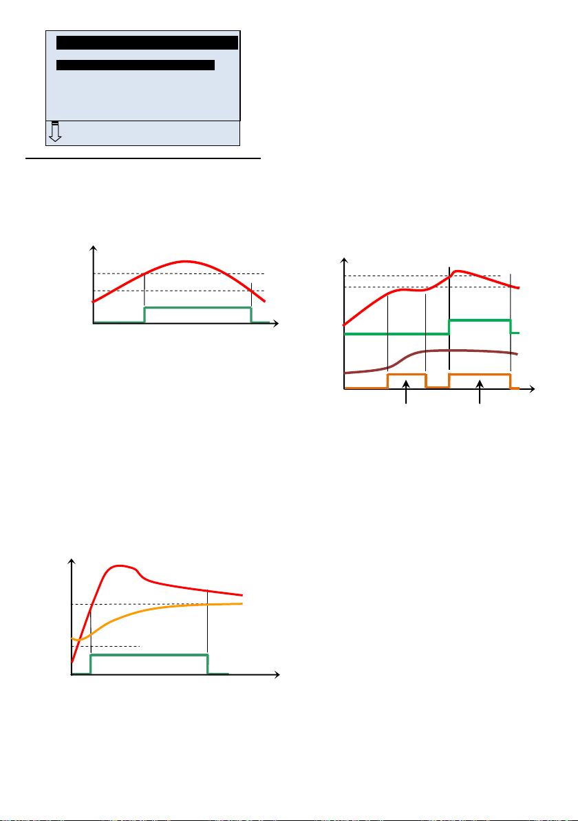
ACHTUNG!
Die installierende Person sollte vor Inbetriebnahm
diese Installations- und Bedienungsanleitung sorgfältig
durchlesen und sich mit den darin enthaltenen Anweisungen
vertraut machen.
Der Solarregler darf nur von speziell ausgebildetem Personal
montiert, bedient und gewartet werden. Personen, die sich
noch in der Ausbildung befinden, dürfen das Gerät nur unter
Aufsicht eines erfahrenen Technikers bedienen.
Bei Arbeiten mit dem Regler sind alle Anweisungen in diesem
Installations- und Wartungshandbuch einzuhalten. Der
Hersteller haftet nicht für fehlerhafte Installationen. Watts haftet
nicht im Falle einer unsachgemäßen Handhabung.
Änderungen und Erweiterungen jeglicher Art sind aus
Sicherheitsgründen untersagt. Wartungsarbeiten am
Solarregler dürfen nur von Kundendienst-Technikern mit
Hersteller-Autorisierung durchgeführt werden.
Der Funktionsumfang des Reglers hängt vom Modell und der
Anlage ab. Dieses Installationshandbuch gehört zum Produkt
und ist Teil des Lieferumfangs.
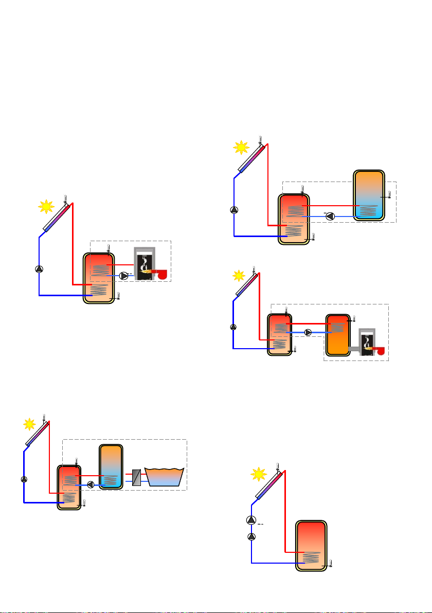
ANWENDUNGSBEREICH
Der Solarregler wurde für Solar-Heizungen entwickelt. Die
Temperatur des Wassers im Speicher wird durch den
Temperaturunterschied „ dt“ zwischen Kollektor und Tank
geregelt.
Normalerweise wird der Regler zusammen m
Solarstation inkl. Umlaufpumpe und mechanischem
Sicherheitsventil verwendet.
Die Regler sind für den Einsatz in Trockenbereichen
ausgelegt, z.B. in Wohnräumen, Büros und Industrieanlagen.
Stellen Sie vor der Inbetriebnahme sicher, dass das Gerät den
geltenden Vorschriften entspricht, um eine ordnungsgemäße
Funktion zu gewährleisten.
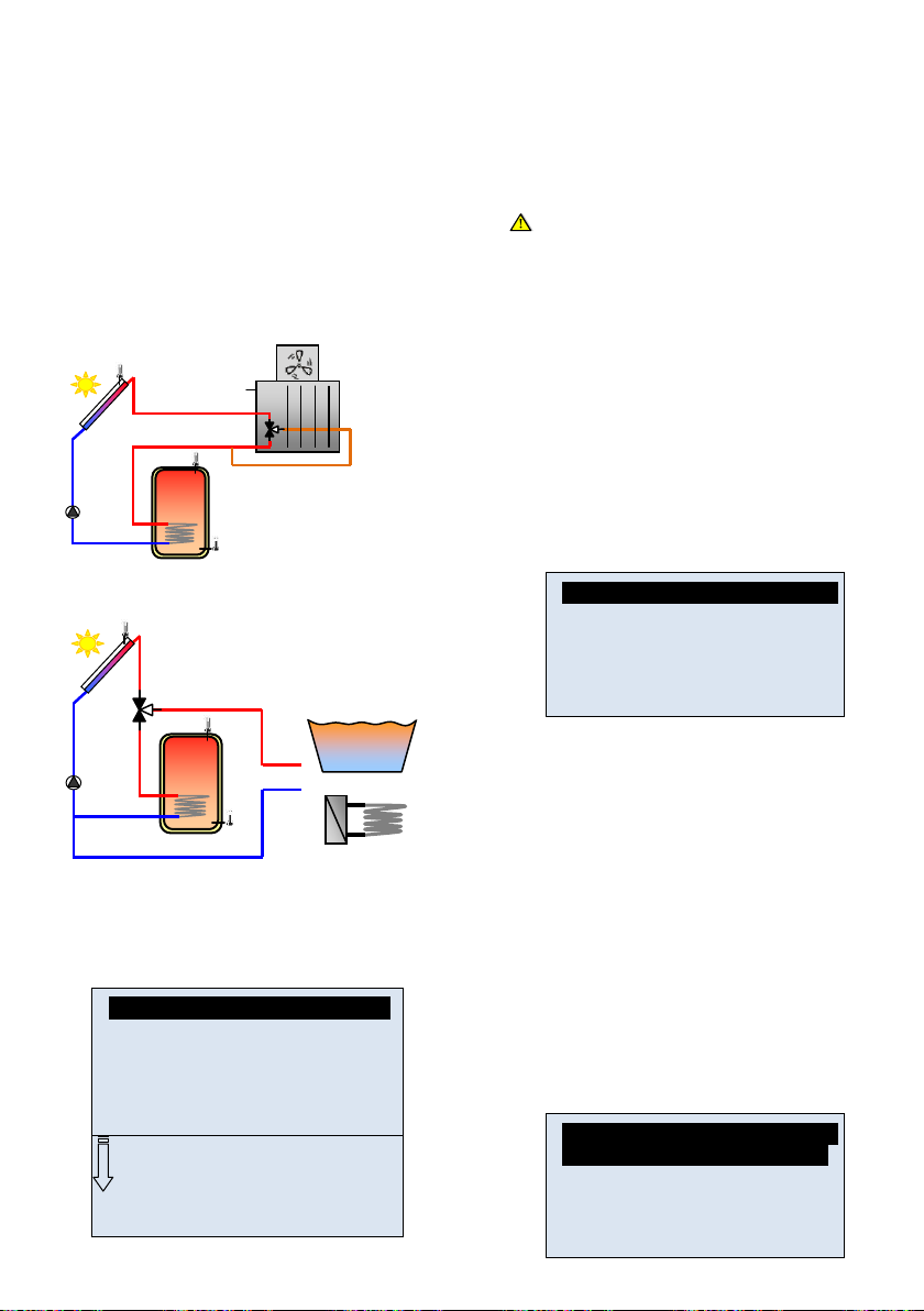
SICHERHEITSHINWEISE
Nehmen Sie die Anlage vor Beginn der Arbeit vom Netz!
Sämtliche Installationsarbeiten und Verkabelungen am Regler
dürfen nur im abgeschalteten Zustand durchgeführt werden.
Das Gerät darf nur von qualifiziertem P
und in Betrieb genommen werden. Die geltenden
Sicherheitsvorschriften sind unbedingt einzuhalten.
Die Regler sind weder Spritzwasser- noch Tropfwasserfest und
sollten deshalb nur an einer trockenen Stelle m
Vertauschen Sie auf keinen Fall die Anschlüsse für die
Sensoren und die 230 V-Anschlüsse. Dies kann zu
lebensgefährlichen Elektroschocks oder zur Zerstörung des
Gerätes sowie der angeschlossenen Sensoren und Geräte
führen.
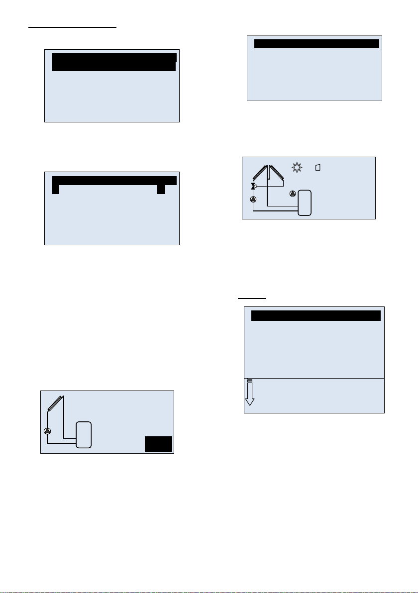
INHALTSVERZEICH
HAUPTMERKMALE ................................................................. 19
TECHNISCHE DATEN ............................................................ 20
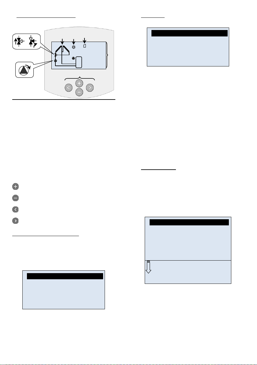
DARSTELLUNG (Display, Tasten) .......................................... 20
1 Einstell-Assistent .................................................. 21
2 Service ................................................................. 22
2.1 Sprache ................................................................ 22
2.2 Zeit & Datum ........................................................ 22
2.3 System ................................................................. 22
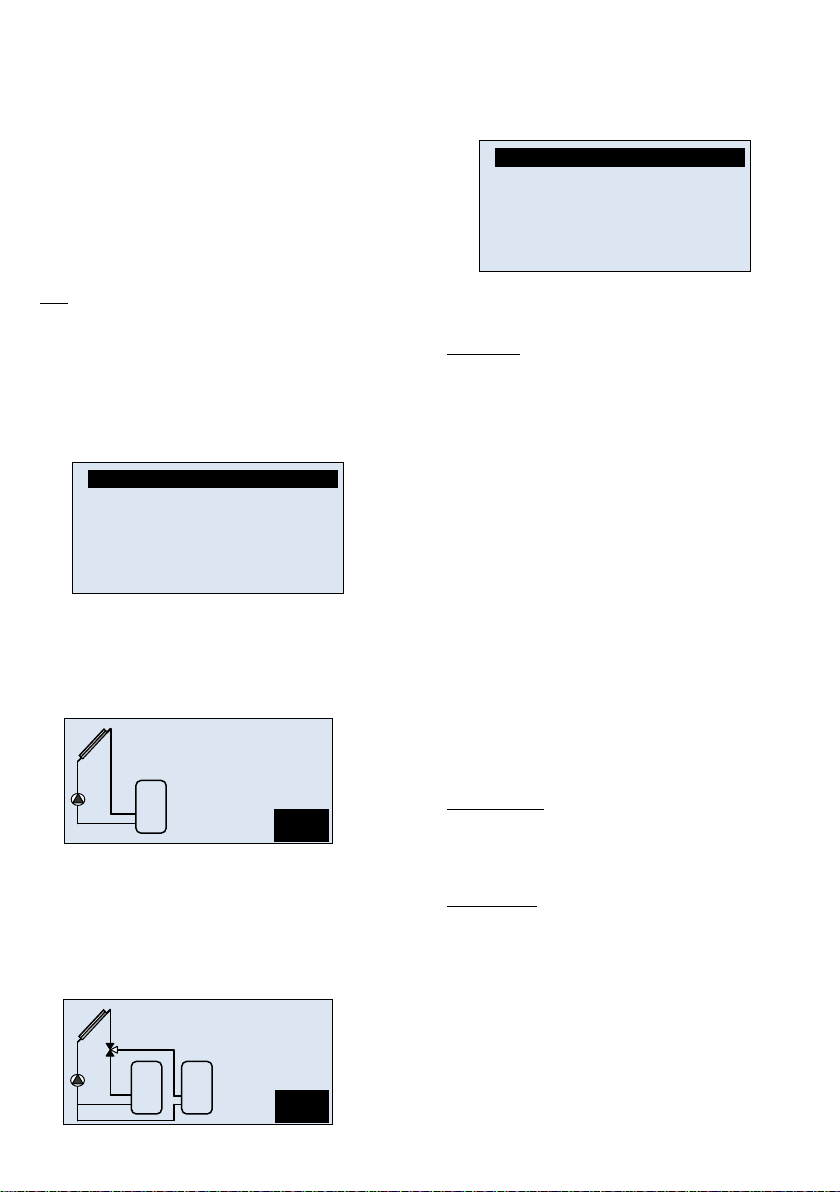
2.3.1 System 1 .............................................................. 22
2.3.2 System 2 .............................................................. 22
2.3.3 System 3 .............................................................. 23
2.3.4 System 4 .............................................................. 23
2.3.5 System 5 .............................................................. 23
2.3.6 System 6 .............................................................. 24
2.3.7 System 7 .............................................................. 24
2.3.8 System 8 .............................................................. 24
2.4 Einstellung Ausgang............................................. 24
2.4.1 P1 ......................................................................... 24
2.4.2 P2 ......................................................................... 25
2.4.3 Pumpe P3 ............................................................ 26
2.5 Einstellung Eingang ............................................. 27
2.5.1 Ohne Durchflussmesser ....................................... 27
2.5.2 Grundfos Sensoren .............................................. 27
2.5.3 Durchflussmessung (Impuls-Meter od Flow-
Meter) 28
2.5.4 Temperatursensor ................................ 28
2.6 Energie-Bilanzierung: ........................................... 28
2.6.1 Solarenergie ......................................................... 28
2.6.2 2. Energie ............................................................. 29
2.7 Schutzfunktionen .................................................. 29
2.7.1 Max Temp ............................................................ 30
2.7.2 Hitzeschutz ........................................................... 30
2.7.3 Kühlung ................................................................ 30
2.7.4 Rückkühlung ........................................................ 30
2.7.5 Frostschutz ........................................................... 30
2.8 °C / °F .................................................................. 30
2.9 Röhrenkollektor .................................................... 30
2.10 Werkseinstellungen: ............................................. 30
3 Menü Einstellungen .............................................. 30
3.1 Maxtemp Speicher1 ............................................. 30
3.2 dTOn Speicher1 ................................................... 30
3.3 dTOff Speicher1 ................................................... 30
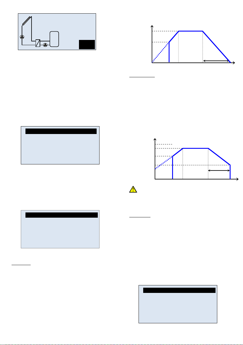
3.4 dTFs: maximale Drehzahl .................................... 31
3.5 Mindesttemperatur Kollektor ................................ 31
3.6 Maxtemp Speicher2 ............................................. 31
3.7 dTOn Speicher2 ................................................... 31
3.8 dTOff Speicher ..................................................... 31
3.9 dTOn rücklauf ....................................................... 31
3.10 dTOff rücklauf ....................................................... 31
ZUSATZFUNKTIONEN ............................................................ 31
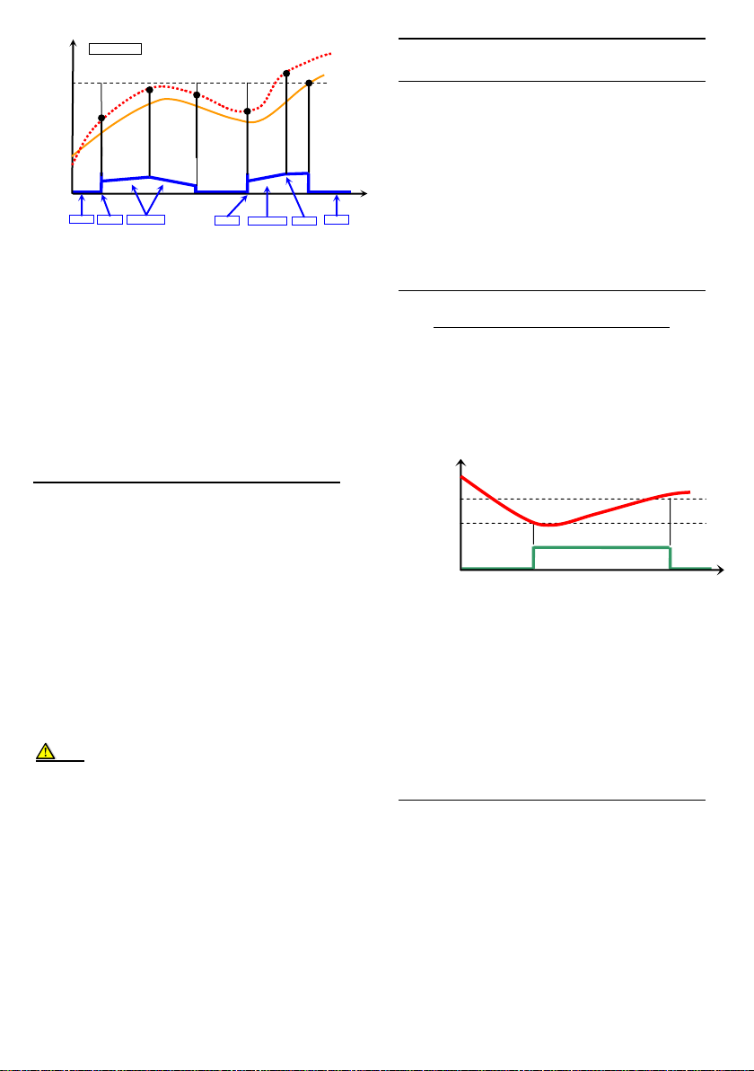
3.11 Thermostatfunktion .............................................. 31
3.11.1 Start...................................................................... 31
3.11.2 Hysterese ............................................................. 31
3.11.3 Verzögerung ......................................................... 31
3.11.4 Legionellenschutz................................................. 31
3.11.5 Timer .................................................................... 31
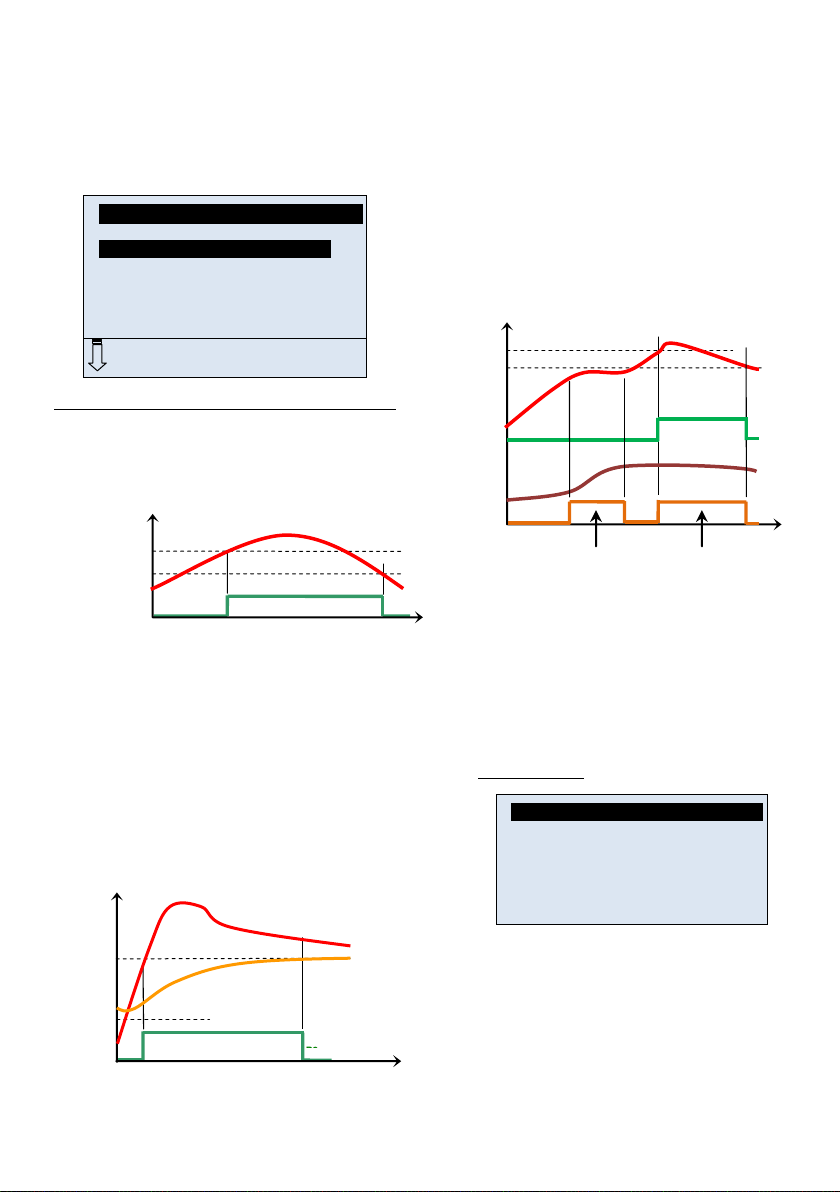
3.12 Kühlfunktion ......................................................... 32
3.12.1 Einschaltung der Kühlung .................................... 32
3.12.2 Kühlhysterese ...................................................... 32
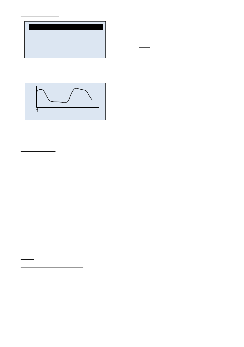
3.13 Differenzregelung ................................................. 32
3.13.1 Max Kalt Speicher ................................................ 32
3.13.2 Min Warm Speicher .............................................. 32
3.13.3 dT On ................................................................... 32
3.13.4 dT Off ................................................................... 32
3.14 Funktion Antistagnation ........................................ 32
3.14.1 Einschaltebene ..................................................... 32
3.14.2 Abschaltebene ..................................................... 32
4 Menü Betrieb ........................................................ 33
4.1 Automatikbetrieb und Ausgeschaltet .................... 33
4.2 Funktion Schornsteinfeger ................................... 33
4.3 Test manuell ......................................................... 33
5 Menü Betriebsstunden ......................................... 33
6 Menü Temperaturen ............................................. 34
7 Spezialfunktionen ................................................. 34
7.1 Festsitzschutz der Pumpe .................................... 34
7.2 Dimmerfunktion .................................................... 34
7.3 Sicherheitsfunktion ............................................... 34
8 Sonstiges ............................................................. 34
9 Notizen ................................................................. 35