571827
4
Zoom out
Zoom in
Previous page
1/36
Next page
DANTA
installation, servicing and user instructions
500 - 800 - 1100 - 1400 - Koto
includes Front, Corner, Bay and Room Divider
IEGB
This appliance has been tested and certied for other counties (see technical data). However
to install appliance in other countries, modication of the appliance and its method
of installation may be necessary in order to use the appliance safely and correctly. The
manual for the local language must be obtained. Contact Wanders for further information.
v.3.3-082017
installation, servicing and user instructions manual | GB + IE
3
© Copyright 2014 Wanders res & stoves
The information contained herein is subject to change without notice. Wanders res & stoves shall not be liable for technical or editorial errors or omissions contained herein.
1. General Notes 4
2. User instructions 5
Operation (remote control with EcoWave) 5
Operation (optional Wanders EcoWave app) 5
2.1 First Time of Operation 5
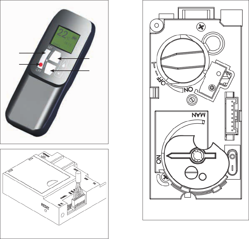
2.2 Remote Control Overview 5
2.3 Batteries 6
2.4 Replacing the batteries 6
2.5 Setting the Transmitter code 6
2.6 To Ignite the appliance 6
2.7 To Turn the appliance OFF 7
2.8 Adjusting the Flame setting 7
2.9 Using the "Eect" Burner 7
2.10 Setting °C/24 hour or °F/12 hour clock 7
2.11 Setting the Time 7
2.12 Cleaning and Maintenance 7
3. Installation instructions 8
3.1 Gas Connection 8
3.2 Ventilation 8
3.3 Appliance Fireplace Installation 8
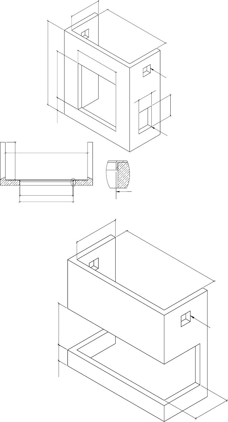
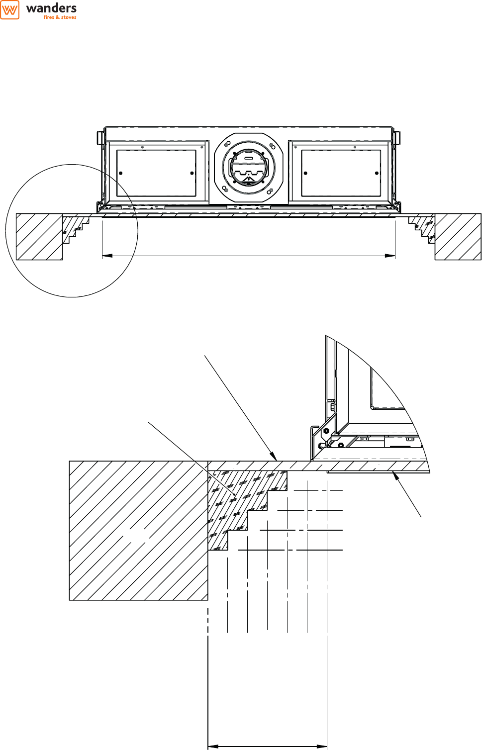
3.3.1 Building the Fireplace 8
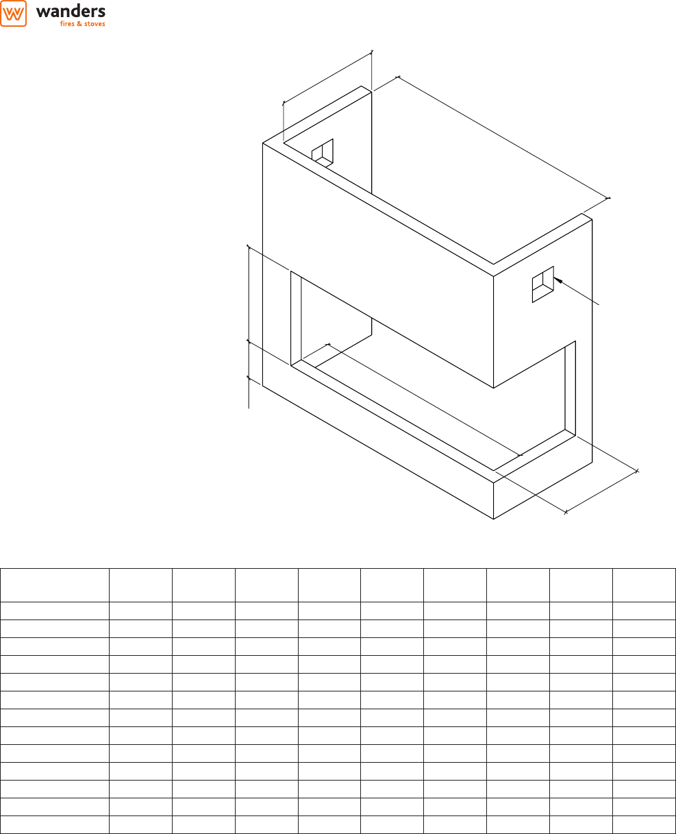
3.3.2 Built-In Fireplace Sizing (assuming a Cement Board Lining is used) 9
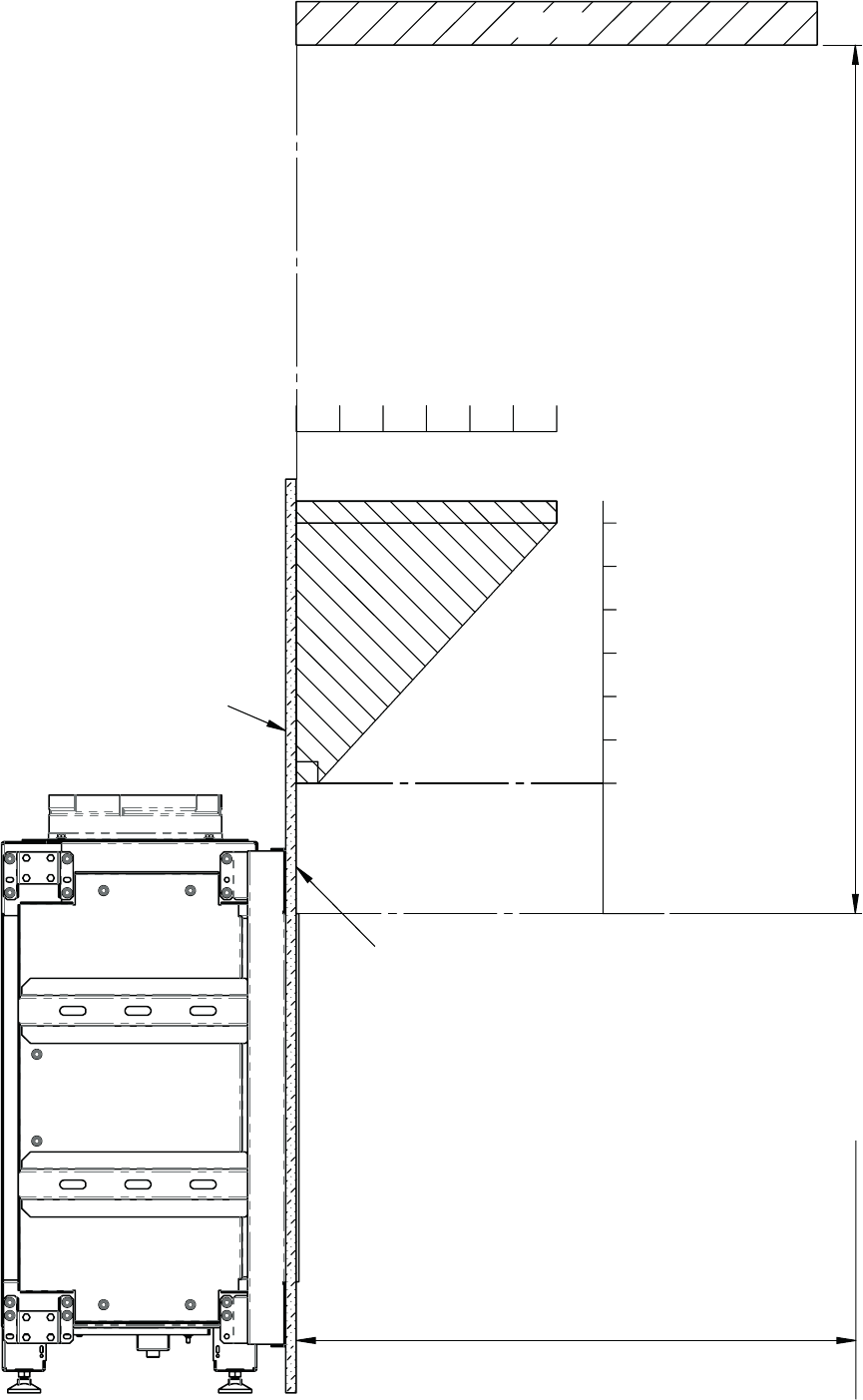
3.3.4 Mantel Clearances 11
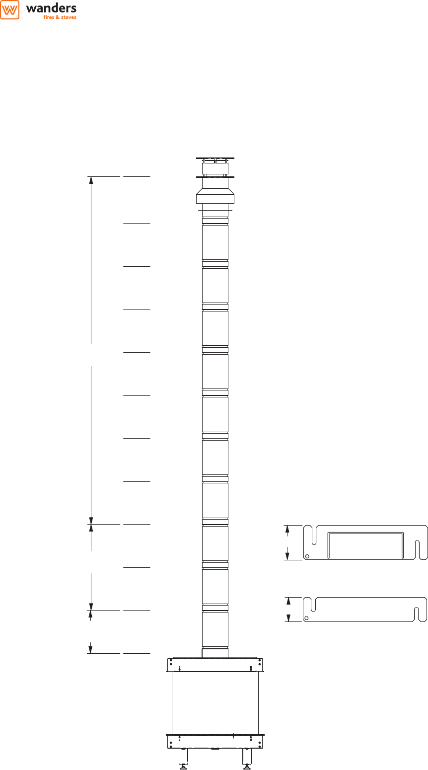
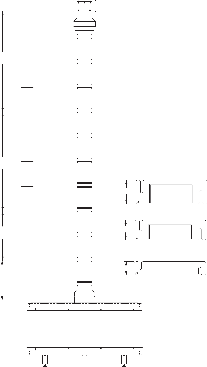
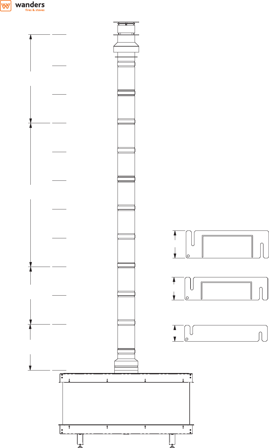
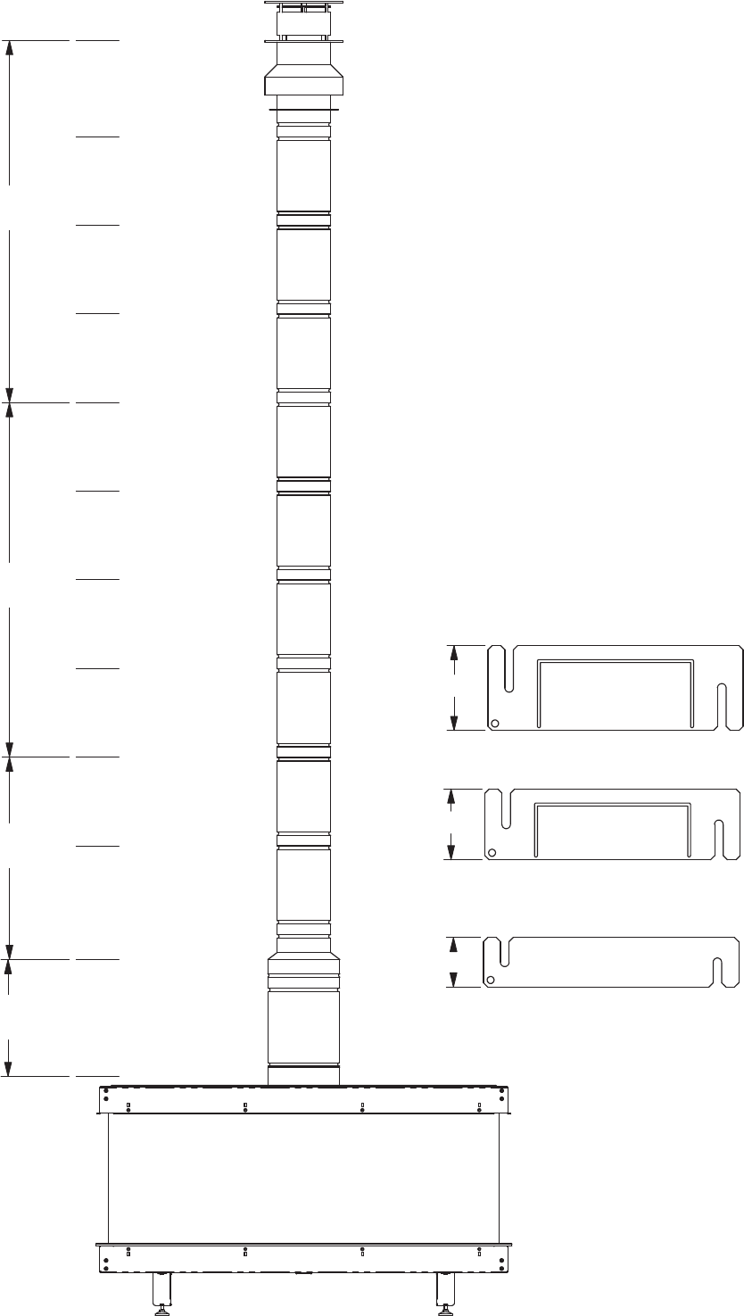
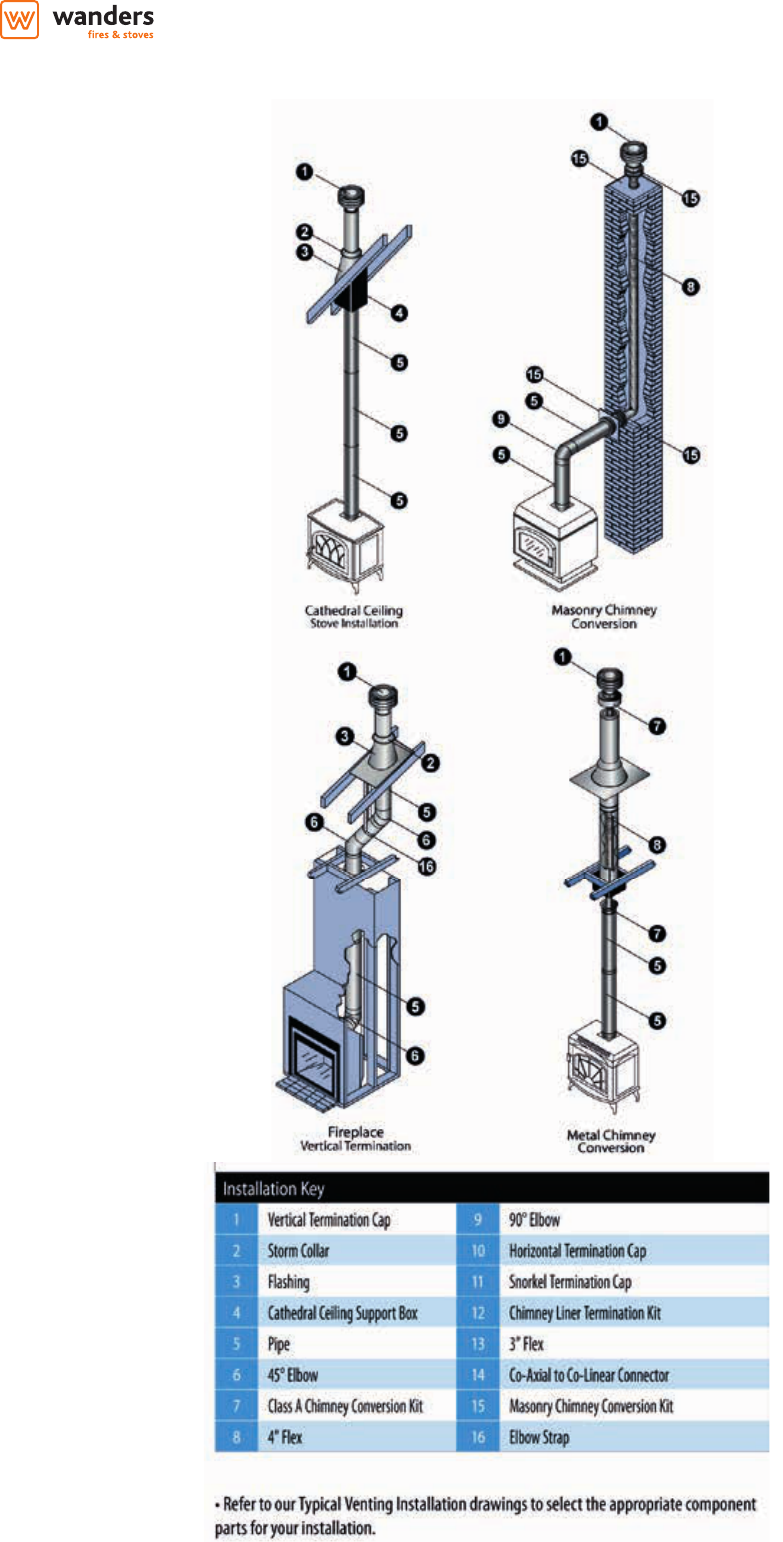
3.4 Flue Connection 13
3.4.1 General notes 13
3.4.2 Timber Frame Construction 13
3.4.3 Carport or Building Extension 13
3.4.4 Basements, Lightwells and Retaining walls 13
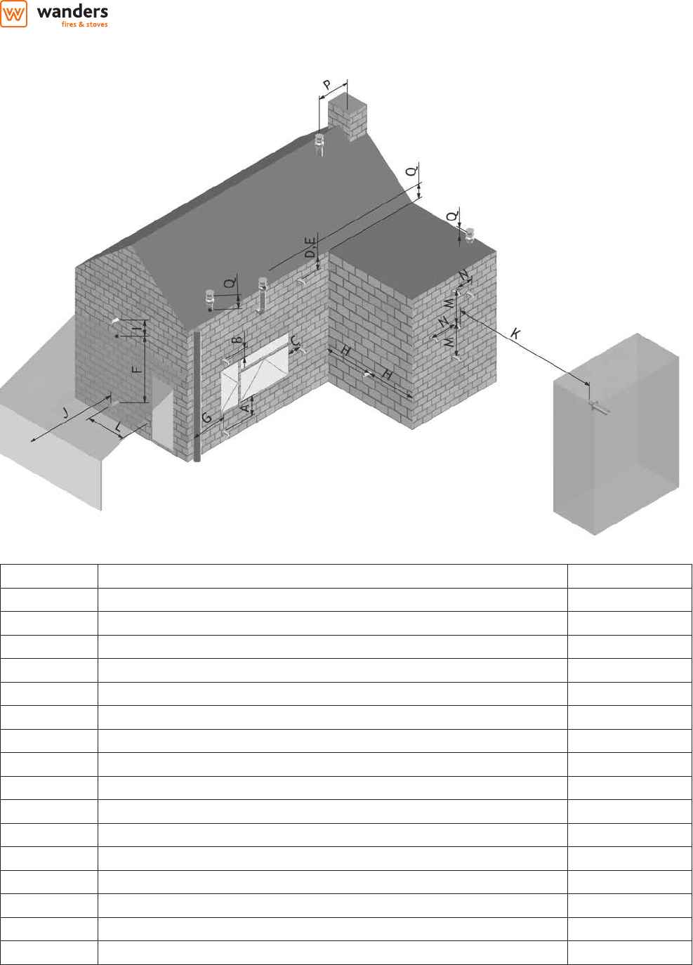
3.4.5 Terminal Locations 14
3.4.6 Horizontal Wall Vent Termination type C11 15
3.4.7 Vertical Roof Vent Termination C31 16
3.4.8 Typical Installations Roof Vent Termination C31 20
3.5 Fuel Bed Media and Arrangements 21
3.5.1 Danta 500 22
3.5.2 Danta 800 22
3.5.3 Danta 1100 23
3.5.4 Danta 1400 & Koto 24
3.5.5 Pebbles 25
3.5.6 Stones 25
3.6 Commissioning the Appliance 26
3.6.1 Pilot Ignition Check 26
3.6.2 Main Burner Check 26
3.6.3 Pressure Check 26
4. Servicing 27
4.1 Cleaning the Ceramics 27
4.2 Servicing the Burners 27
4.3 Spare parts 28
4.4 Flue pipes 28
5. Technical Information 29
5.1 Countries of Use 29
5.2 Technical Data 30
5.2.1 Danta 500 30
5.2.2 Danta 800 30
5.2.3 Danta 1100 & Koto 31
5.2.4 Danta 1400 31
6. Electric wiring 32
4
1. General Notes
This Wanders gas appliance is a High Eciency, Balanced Flue Live Fuel Eect appliance. It provides radiant and
convected heat using the latest burner technology. As well as having a variable heat output, these res also utilise
a special control system that allows the appliance to use two burners for high output or a single burner for lower
outputs.
One of the burners will be designated as the "Main" Burner, this is the Front, the second burner will be designated
as the "Eect" Burner. The Eect burner can be switched ON or OFF whilst the appliance is alight.
Before Installation, check that the local distribution conditions, nature of the gas and pressure, and adjustment of
the appliance are compatible.
This appliance is intended for use on a gas installation with a governed meter.
This Gas Installation may only be installed by a registered professional competent person (Gas Safe installer in the
UK). The installation must adhere to the requirements of the local and national Building regulations and national
standards. The installation manual must also be followed.
Ensure that the Flue Terminal is not in any way obstructed and is clear of vegetation, i.e. trees, shrubs etc. and that
no objects are leant against the terminal or guard.
Always clean the Window Panel before the re is ignited. Any nger prints must be removed, as these will be burnt
into the glass and will be un-removable.
Do not operate this appliance if the glass panel has been broken (or cracked), removed or is open.
The appliance is designed to t numerous installation situations as listed in these installation instructions. However
only ue approved by Wanders for this appliance may be used.
This appliance is a balanced ue product and is room sealed and as such requires no additional ventilation for
operation. However an adequate supply of fresh air to maintain temperatures and a comfortable environment is
recommended.
This appliance is designed as a heating appliance, and as such will get very hot in operation; all surfaces (except
the controls and access door) are considered to be working surfaces and as such should not be touched. The front
windows and surrounds are not considered to be fully secure guards against accidental contact. It is recommended
that an approved re screen be used if children, the elderly or persons with limited mobility are to be present in
the same area.
Do not place curtains, laundry, furniture etc. within a safe distance of 300mm of this appliance.
Do not attempt to burn rubbish on this appliance.
If this appliance is extinguished, on purpose or other, no attempt to relight should be made within 3 minutes.
installation, servicing and user instructions manual | GB + IE
5
2. User instructions
Operation (remote control with EcoWave)
For the complete explanation of the operation via the SYMAX-remote control, please refer to the instruction
manual supplied separately.
Operation (optional Wanders EcoWave app)
It is possible to order the optional Wi-Fi module in order to operate the replace using the Wanders EcoWave app,
The app can be downloaded for free at the Apple App Store and/or the Google Play Store. Incidentally, the app
can only be used in combination with the SYMAX EcoWave remote control.
2.1 First Time of Operation
Before igniting the appliance, ensure that all packaging, safety stickers and any protective wrapping have been
removed, and that the glass has been cleaned, including all ngerprints from the glass.
Ensure that the room is adequately ventilated the rst time that the appliance is ignited; we would recommend
opening windows if possible. Run the appliance at full setting for a few hours so that the paint gets an opportunity
to fully cure. During this period it is possible for some fumes and vapours to be given o. We would recommend
keeping children and pets out of the area at this time.
2.2 Remote Control Overview
This Wanders Gas Appliance has been constructed with an advanced remote control system. This consists of three
main parts; Handset (g. 1.1), Receiver (g. 1.2) and Gas Valve with Manual Override (g. 1.3). The Gas control valve
and the Receiver are behind the access door. This is also where the product Data Label is located.
g. 1.2. Remote Receiver
g. 1.1. Remote Handset
A
B
C
D
g. 1.3. Gas Control Valve
6
The Remote Handset has 4 Buttons; these will perform all operations of the re.
Always leave the dial on the Gas Control Valve set to "ON", the "MAN" position is only for servicing and
emergency use if the handset is misplaced, or the battery fails.
With each successful button press of the handset, the receiver will emit an audible signal.
A toggle switch is present on the Gas Control Valve; this should be put into the "O" position if the appliance is
not operated for a long period (over a week).
The heat output can be manually adjusted by turning the setting knob on the Gas Control Valve.
2.3 Batteries
Remote Handset:
1 x 9V "PP3" Battery, Quality alkaline recommended
Receiver:
4 x 1.5V "AA", Quality alkaline recommended for maximum life.
An alternative AC Mains Adaptor may be used to power the Receiver instead of the 4 AA batteries. Only an AC
Mains Adapter supplied by Wanders may be used. The Mains Adaptor is plugged into the DC 6V socket on the end
of the receiver.
Note - if the AC Mains Adapter is used, remove the 4 AA's from the Receiver, failure to do so could result in damage
and failure of the Receiver. During a period of power outage, the receiver may be unplugged and batteries returned
to the Receiver.
2.4 Replacing the batteries
Handset:
There is a battery level indicator on the display of the handset. When this gets low remove the cover on the rear of
the handset and replace the battery with another 9V PP3 battery.
Receiver:
Three short audible beeps will sound when the appliance is on to indicate that the batteries in the receiver are
getting low.
When the batteries get very low the appliance will be turned o by the remote control. This will fail to happen if
the power supply is interrupted.
To replace the Receiver batteries, slide the cover o of the top of the receiver and use the ribbon to pull the
batteries out. Replace the batteries with new 1.5V AA's, ensuring that the ribbon is located under the batteries and
that the polarity is correct on all 4 batteries.
Never mix new batteries with old; this will result in the new batteries being emptied very quickly.
When the batteries are replaced, it may be necessary to reset the transmitter code, as detailed in the next section.
2.5 Setting the Transmitter code
Press and hold the RESET button with a sharp object (pen or screwdriver) until you hear two audible beeps. After
the second, longer beep, release the RESET button.
Within the next twenty seconds press the down button (Button D g 1.1) on the remote handset until you hear an
additional long signal conrming the code is set.
2.6 To Ignite the appliance
Note - If this appliance is extinguished or goes out in use for any reason, wait 3 minutes before attempting to
relight the appliance. The Gas Control Valve has an interlock device which will not allow relighting until the 3
minutes have passed.
To be able to use the Remote control Handset (g. 1.1), the rocker switch on the Gas Valve, must be turned "ON"
(the "1" position) and the manual Dial set to the "On" position.
installation, servicing and user instructions manual | GB + IE
7
Simultaneously press and hold buttons B & C (Star and Large Flame), until a short acoustic beep conrms the
start sequence has begun; release the buttons.
Continuing signals conrm the ignition is in process.
Once pilot ignition is conrmed, there will be gas ow and the main burner will ignite.
Repeat process if pilot ignition fails.
2.7 To Turn the appliance OFF
Press the OFF button (Button B g. 1.1) on the Handset. This will extinguish all Burners including Pilot.
Note: - Repeated presses of the small ame (Button D g. 1.1) will turn the main burner OFF, but will leave the Pilot
alight.
2.8 Adjusting the Flame setting
To increase the ame height; press the large ame button (Button C g. 1.1).
To decrease the ame height; press the small ame button (Button D g. 1.1).
2.9 Using the "Eect" Burner
Note: The solenoid valve will not operate for one minute after Ignition.
The solenoid valve cannot be operated manually. If the battery runs down, the solenoid will remain in its
last operating position.
During normal operation the solenoid will be reset to the ON (Open) when the Gas Valve is switched OFF
via the Handset.
Upon ignition both "Main" and "Eect" burner are ON.
To switch the "Eect" burner OFF, simultaneously press the OFF and Large Flame buttons (buttons B & C g. 1.1).
To switch the "Eect" burner ON, simultaneously press the SET and Large Flame buttons (buttons A & C g. 1.1).
Printed instructions are located on the battery cover on the rear of the handset.
2.10 Setting °C/24 hour or °F/12 hour clock
Simultaneously press OFF and Small Flame buttons (buttons B & D g. 1.1) until display changes from Fahrenheit/12
hour clock to Celsius/24 hour clock and vice versa.
2.11 Setting the Time
The display will ash after either:
Installing the battery or
Simultaneously pressing the Large Flame Button and Small Flame Button (buttons C & D g. 1.1)
Press the Large Flame button (button C g. 1.1) to set the hour.
Press the Small Flame button (button D g. 1.1) to set the minutes.
Press OFF (button B g. 1.1) to return to standard operating mode or simply wait and it will return to standard
mode after approximately 15 seconds.
2.12 Cleaning and Maintenance
This appliance should be inspected and serviced once a year by a qualied, competent and registered person.
The inspection and maintenance must at least ensure that the appliance is working correctly and safely. It is
advisable to clean the appliance of any dust and debris before regularly during the heating season and especially
if the appliance has not been used for some time. This can be done with a soft brush and a vacuum cleaner or a
damp cloth and if required a non-abrasive cleaning agent. Do not use corrosive or abrasive substances to clean
the appliance.
8
3. Installation instructions
Before commencing Installation, conrm that the details on the appliance data plate correspond to the local
distribution conditions, gas type and pressure to which the appliance is to be installed.
Ensure that gas supply and supply pipe is capable of delivering the required volume and pressure of gas and is in
accordance with the rules in force.
3.1 Gas Connection
This appliance has a gas inlet connection of Ø 8mm.
3.2 Ventilation
This appliance is a Balanced Flue room sealed appliance, and as such needs no additional ventilation. However an
adequate supply of fresh air to maintain temperatures and a comfortable environment is recommended.
This appliance may be installed in a completely sealed or mechanically ventilated house.
3.3 Appliance Fireplace Installation
Determine the position required for the appliance.
Create a gas connection for the appliance in approximately the correct location for the gas controls.
The gas controls are connected to the Burner of the appliance. These controls need to be located in the
control access box, so an appropriate position for the access box needs to be determined.
This appliance has fully adjustable legs, these must me set to the desired length before the ue position is
nalised. Fine adjustment of the legs is available via the feet.
Do not make any adjustments to the appliance, except the leg length.
The appliance should be tted with a minimum clearance of 150mm from any combustible objects or
materials; this includes any combustible materials used for the replace construction. This clearance distance
can be reduced to 50mm if a Cement Board, of minimum thickness 12mm is used. This Cement Board will act
as a Thermal Break.
The clearance distance of the Flue from combustibles must not be less than 75mm. This dimension can be
reduced to 25mm as the distance from the underside and the sides of Horizontal Flue runs.
As this is a room sealed appliance and the appliance stands on appropriate legs, a hearth is not required for
this appliance.
The Fireplace should be ventilated with openings giving a total free vent area of 200 cm².
A gap of 50mm should be left all round the appliance.
If a shelf is to be tted above the replace opening, a gap of 150mm minimum should be left between the
opening and the shelf.See section 3.3.3, Mantel Clearances.
The brackets supplied may be used for securing the appliance to a rear wall.
3.3.1 Building the Fireplace
Construct a studwork replace to the desired sizes, minimum sizes are shown in section 3.3.2. Any combustible
material used to construct the Fireplace must not be closer than the minimum dimensions quoted in section
3.3 above. Cement Board of minimum thickness 12mm, can be used as a Thermal Break and can be used
directly against the Frame Face on the appliance.
Do not use insulation material (or other) to pack the void around or above the appliance.
Provide ventilation from the replace to the minimum amount quoted in 3.3 above.
Provide a cut-out for the Control Access Door.
installation, servicing and user instructions manual | GB + IE
9
3.3.2 Built-In Fireplace Sizing (assuming a Cement Board Lining is used)
C
F
B
E
D
250
A
175
Free Vent Area
200 cm²
Control
Access
Door
Cut-out
C
A
D
Max plaster
Y
Max. Plaster point
Detail Y
C
E
D
B
G
Free Vent Area
200 cm²
Built in replace sizing
Bay and Room Divider
10
Appliance A min B min C min D min E min F min G min G2 min H min
Danta 500 Front 515 375 650 490 195 700 n/a n/a n/a
Danta 500 Bay n/a 375 555 490 195 700 355 355 n/a
Danta 500 Corner n/a 375 600 490 195 700 355 n/a 515
Danta 800 Front 815 375 850 490 195 700 n/a n/a n/a
Danta 800 Bay n/a 375 855 490 195 700 355 355 n/a
Danta 800 Corner n/a 375 900 490 195 700 355 n/a 815
Danta 1100 Front 1115 375 1150 490 195 700 n/a n/a n/a
Danta 1100 Bay n/a 375 1155 490 195 700 355 355 n/a
Danta 1100 Corner n/a 375 1200 490 195 700 355 n/a 1115
Danta 1100 Front 1415 375 1450 490 195 700 n/a n/a n/a
Danta 1100 Bay n/a 375 1455 490 195 700 355 355 n/a
Danta 1100 Corner n/a 375 1500 490 195 700 355 n/a 1415
Koto 1316 395 1500 425 195 750 n/a n/a n/a
C
E
D
B
G
H
Free Vent Area
200 cm²
Built in replace sizing
Corner appliances
installation, servicing and user instructions manual | GB + IE
11
3.3.4 Mantel Clearances
3.3.4.a Combustible Mantel – Side view
1m (40") Minimum to ceiling
Do not place furniture or any other objects
within 1m (40") of the front of appliance
0 50
(2")
150
(6")
200
(8")
100
(4")
250
(10")
300
(12")
Fireplace Opening
Cement Board
Minimum
12mm (1/2") Thick
0
150 (6")
200 (8")
250 (10")
300 (12")
350 (14")
400 (16")
450 (18")
Mantel Projection
(from face of Cement Board)
Ceiling
Mantel Height
(from Fireplace Opening)
Face of
Finished Wall
12
3.3.4.b Combustible Mantel/Side Wall – Top view
installation, servicing and user instructions manual | GB + IE
13
3.4 Flue Connection
3.4.1 General notes
This appliance may be installed with a roof terminal (C31) or a wall terminal (C11).
This appliance may only be used with Balanced Flue (otherwise known as Concentric Flue) parts as specied by
Wanders. The Wanders specied ue parts have been approved with the appliance. If the appliance is installed
on non-Wanders approved parts, Wanders cannot guarantee or accept and responsibility for the proper and safe
working of the appliance.
The ue system must be constructed from the appliance upwards, with all joints being fully locked and sealed
using the Wanders specied parts.
3.4.2 Timber Frame Construction
Whilst it is possible to install room-sealed appliances in timber frame properties, great care needs to be taken to
ensure that the ue assembly does not interfere with the weather proong qualities of any outer wall which it
may penetrate. Before attempting this work, further details need to be referenced, (e.g. “Gas Installations in Timber
Frame Buildings from the CORGI installer series in the UK).
3.4.3 Carport or Building Extension
Where a ue terminal is sited within a carport or building extension, it should have at least two completely open
and unobstructed sides. The distance between the lowest part of the roof and the top of the terminal should be
at least 600mm.
Note: A covered passageway should not be treated as a carport. Flues should not be sited in a covered passageway
between properties.
3.4.4 Basements, Lightwells and Retaining walls
Flue terminals should not be sited within the connes of a basement area, light well or external space formed by a
retaining wall, unless steps are taken to ensure the products of combustion can disperse safely at all times. It may
be possible to install this Balanced Flue system in such a location provided that it is not sited lower than 1m from
the top level of that area to allow combustion products to disperse safely.
Flue terminals should be sited to ensure total clearance of the combustion products in accordance with the
included information.
When the products of combustion are discharged, they should not cause a nuisance to adjoining or adjacent
properties and they should be positioned so that damage cannot occur to other parts of the building. If the outer
wall surface is constructed of combustible material, a non-combustible plate should be tted behind the terminal
projecting 25mm beyond the external edges of the terminal.
14
3.4.5 Terminal Locations
Dimension Terminal Position Distance (mm)
A* Directly below an opening, air brick, opening window etc. 600
B Above an opening, air brick, opening window etc. 300
C Adjacent to an opening, air brick, opening window etc. 400
D Below gutters, soil pipes or drain pipes 300
E Below eaves 300
F Below balconies of car port roof 600
G From a vertical drain pipe or soil pipe 300
H From an internal or external corner 600
I Above ground roof or balcony level 300
J From a surface facing the terminal 600
K From a terminal facing the terminal 600
L From an opening in the car port (e.g. door , window into the dwelling) 1200
M Vertically from a terminal on the same wall 1500
N Horizontally from a terminal on the same wall 300
P From a vertical structure on the roof 600
Q Above intersection with roof 150
* In addition, the terminal should not be nearer than 300mm to an opening in the building fabric
formed for the purpose of accommodating a built in element such as a window frame.
installation, servicing and user instructions manual | GB + IE
15
3.4.6 Horizontal Wall Vent Termination type C11
Flue sizing:
Danta 500: Ø100/150 Connector on Appliance. Ø100/150 to be used Throughout.
Flue Terminal: Ø100/150 Part No. INK.4330
Danta 800, 1100, 1400 & Koto: Ø130/200 Connector on Appliance. Ø130/200 to be used Throughout.
Flue Terminal: Ø130/200 Part No. INK.4430
Vertical Flue
Rise (V) in
metres
Maximum
Horizontal Flue Run
(H) in metres Danta
500
Maximum
Horizontal Flue Run
(H) in metres Danta
800
Maximum
Horizontal Flue Run
(H) in metres Danta
1100 & Koto
Maximum
Horizontal Flue Run
(H) in metres Danta
1400
0,5 1 2 1,75 1,5
1 2,5 3,5 3 2,5
1,5 3,5 5 4,25 3,5
2 4 6 5,5 4,5
2,5 4,5 6 6 5,5
3 5 6 6
3,5 5,5 6
4 6
4,5 6
Minimum Vertical Flue Height: 0.5m
Flue Restrictors to be tted:
Ø100/150, Vertical Rise < 1m, No Restrictor.
Ø100/150, Vertical Rise > 1m, 35mm Restrictor.
Ø130/200, Vertical Rise, 1m, No Restrictor.
Ø130/200, Vertical Rise 1-2m, 35mm Restrictor.
Ø130/200, Vertical Rise > 2m, 60mm Restrictor.
16
3.4.7 Vertical Roof Vent Termination C31
Flue sizing:
Danta 500: Ø100/150 Connector on Appliance,Ø100/150 to be used Throughout.
Flue Terminal: Ø100/150 Part No. INK.4335
Danta 800, 1100, 1400 & Koto: Ø130/200 Connector on Appliance,Ø130/200 to be used Throughout.
Flue Terminal: Ø130/200 Part No. n/a
Minimum Vertical Flue Height: 0.5m
RESTRICTOR
0-1m NO
RESTRICTOR
1-3m 35mm
3-11m 50mm
RESTRICTOR
50
50mm
RESTRICTOR
35mm
RESTRICTOR
35
MAXIMUM VERTICAL FLUE
FOR DANTA 500 AND
FLUE RESTRICTOR SELECTION
100/150 FLUE USED
THROUGHOUT
5
6
7
8
9
0
2
1
3
4
10
Vertical Rise (m)
11
(Max.)
installation, servicing and user instructions manual | GB + IE
17
RESTRICTOR
1-3m 35mm
RESTRICTOR
3-7m 50mm
0-1m NO
RESTRICTOR
7-11m 60mm
RESTRICTOR
60mm
RESTRICTOR
60
35mm
RESTRICTOR
35
MAXIMUM VERTICAL FLUE
FOR DANTA 800 AND
FLUE RESTRICTOR SELECTION
200/130 SPIGOT ON APPLIANCE
200/130 - 150/100 REDUCER ONTO
SPIGOT, 150/100 FLUE USED
THERE AFTER.
50mm
RESTRICTOR
50
4
6
5
7
8
10
(Max.)
0
2
1
3
9
11
Vertical Rise (m)
18
RESTRICTOR
1-3m 35mm
RESTRICTOR
3-8m 50mm
0-1m NO
RESTRICTOR
8-11m 60mm
RESTRICTOR
MAXIMUM VERTICAL FLUE
FOR DANTA 1100 (& KOTO) AND
FLUE RESTRICTOR SELECTION
200/130 SPIGOT ON APPLIANCE
200/130 - 150/100 REDUCER ONTO
SPIGOT, 150/100 FLUE USED
THERE AFTER.
35mm
RESTRICTOR
35
50mm
RESTRICTOR
50
60mm
RESTRICTOR
60
8
9
10
(Max.)
0
2
1
3
4
5
6
7
11
Vertical Rise (m)
installation, servicing and user instructions manual | GB + IE
19
RESTRICTOR
1-3m 35mm
RESTRICTOR
3-7m 50mm
0-1m NO
RESTRICTOR
7-11m 60mm
RESTRICTOR
35mm
RESTRICTOR
35
60mm
RESTRICTOR
60
MAXIMUM VERTICAL FLUE
FOR DANTA 1400 AND
FLUE RESTRICTOR SELECTION
200/130 SPIGOT ON APPLIANCE
200/130 FLUE USED FOR 1st
METRE (Min), THEN
200/130 - 150/100 REDUCER
150/100 FLUE USED
THERE AFTER.
8
9
10
(Max.)
0
2
1
3
4
5
6
7
11
Vertical Rise (m)
50mm
RESTRICTOR
50
20
3.4.8 Typical Installations Roof Vent Termination C31
installation, servicing and user instructions manual | GB + IE
21
3.5 Fuel Bed Media and Arrangements
When arranging the Media in the Fire, it is always important to keep the Pilot area clear and ensure smooth cross
lighting from the Pilot to the Main Burner and of the E ect burner from the Main burner.
Prevent that the embers block the pilot  ame (A) and the burner holes (B) to keep the  re safe and free from
soothing. See image on page 26.
A
B
C
D
E
F
G
H
Zakjes met
schors
Zakje met
gloeihaar
Bags with
embers
Bag with
glow threads
22
3.5.1 Danta 500
3.5.2 Danta 800
Used logs: B - D - D - G (See page 26 for additional information)
Used logs: A - D - D - G - G - E - F (See page 26 for additional information)
installation, servicing and user instructions manual | GB + IE
23
3.5.3 Danta 1100
Used logs: A - D - D - G - G - E - F (See page 26 for additional information)
24
3.5.4 Danta 1400 & Koto
Used logs: A - D - D - G - G - E - F - H - H (See page 26 for additional information)
installation, servicing and user instructions manual | GB + IE
25
3.5.5 Pebbles
Scatter the bag of Pebbles over the top of the Burners and Grate, making sure that the Pilot area is left clear.
Ensure smooth cross lighting of the Burners.
3.5.6 Stones
Scatter the bag of Stones over the top of the Burners and Grate, making sure that the Pilot area is left clear.
Ensure smooth cross lighting of the Burners.
26
3.6 Commissioning the Appliance
3.6.1 Pilot Ignition Check
1. Ignite the pilot light as described in the User Instructions
2. Check that the pilot  ame stays alight
3. Extinguish the pilot light
3.6.2 Main Burner Check
1. Ignite the pilot light as described in the User Instructions
2. Turn on the main burner as described in the User Instructions
3. Check that the pilot smoothly cross-lights to the main burner and that the main burner and pilot stay alight
4. Check the operation of the second e ect burner as described in the User Instructions
5. Extinguish the appliance fully
3.6.3 Pressure Check
The appliance is preset to give the correct heat inputs as listed in the technical details. No further adjustment is
necessary. Always check the inlet pressure and burner pressure.
1. Turn o the gas valve on the appliance
2. Release the screw on the Inlet Pressure test point on the gas valve and connect a manometer
3. Check that the measured pressure is as the prescribed supply pressure
4. Perform the test when the appliance is burning on full (inc. e ect burner) and with only the pilot alight
5. If the pressure is low, check the gas supply pipes are too a correct sizing
6. If the pressure is too high (more than 5 mbar over) the appliance may be installed, but the gas supply company
should be contacted
7. Release the screw on the Burner Pressure test point on the gas valve and connect a manometer
8. Check that the measured pressure is as detailed in the Technical details
9. The measured value should be within +/- 10% of the described value. If this is not the case, please contact the
supplier.
Note: After checking the pressures and removing the manometers, the screws in the Pressure Test points must be
closed, and the system must be checked for gas-tightness.
A
B
Prevent that the embers block the pilot  ame (A) and the burner holes (B) to keep the  re safe and free from
soothing.
installation, servicing and user instructions manual | GB + IE
27
4. Servicing
Turn the appliance OFF and isolate the gas supply. Ensure the appliance is fully cold before attempting to start
servicing the appliance. No liability can be accepted by Wanders for injury caused by burning or scolding by a hot
appliance.
A suggested procedure for servicing is listed below.
A. Lay out dust sheet on ooring, mask o any special replace materials.
B. Remove Side Window Trims
C. Remove Bottom Window Trim
D. Remove Window Assembly
E. Carefully remove the Ceramic components (including Embers) or Gravels
F. Use a Vacuum cleaner to clean the top of the burners and grate
G. Remove Grate
H. Remove all 3 Burner Top assemblies, there are 3 M6 ange bolts holding each in
I. Using a vacuum cleaner, fully clean both Burner Top.
J. With the Burner Tops now removed, the Pilot and the heads of the injectors are clearly visible. Use the
vacuum cleaner and a soft brush to clean the pilot assembly and both Injectors. Never modify or bend the
Thermocouple
K. Replace the burner top assemblies and x in with the xings
L. Turn on the gas supply and check for leaks, check the burners and Pilot for good condition and operation
M. Replace Grate
N. Replace the Firebed arrangements
O. Replace Window Assembly and Trims
P. Check the ue system and terminal, making sure that the terminal vent is fully clear
Q. Light the appliance and test setting pressures
R. Check the safe operation of the appliance.
4.1 Cleaning the Ceramics
Remove the ceramics as detailed in A - E above.
Gently clean the ceramics in the open air, using a soft brush and a vacuum cleaner. Where necessary replace
damaged components only with genuine Wanders specied parts. Seal any scrap ceramics in plastic bags and
dispose at proper refuse sites. When using a vacuum cleaner, it is recommended that one with a HEPA ltering
system is used.
Re-t the Firebed arrangement, re-seal the appliance and check the safe operation of the appliance.
4.2 Servicing the Burners
Remove the Burner Top Assemblies as detailed in A - H above.
The pilot is now clearly visible, the pilot, including the Thermocouple, can be replaced/serviced by removing
raising the pilot assembly from its mounting. This is done by removing the two screws on the surface of the
pilot. The ttings on the under-side of the pilot can be un-done using a 10mm spanner where appropriate.
To access the Main Burner Injectors, the Burner base units must be removed. This is done by removing the six
bolts (M6, 10mm spanner) holding the burner in. With these six bolts removed, the Burner base can be raised
up through the Firebox, and the Injectors can be easily accessed.
When replacing any parts use only original Wanders specied parts.
28
4.3 Spare parts
Part description Partnumber for
Danta 500
Partnumber for
Danta 800
Partnumber for
Danta 1100
Partnumber for
Danta 1400
Partnumber for
Koto
Glass (front) GLA.00.0770 GLA.00.0750 GLA.00.0720 GLA.00.0700 GLA.00.0798
Glass (side) GLA.00.0730 n/a
Glass (back) GLA.00.0780 GLA.00.0760 GLA.00.0740 GLA.00.0710 GLA.00.0798
Log set INK.00.6030 INK.00.6031 INK.00.6032 INK.00.6033 INK.00.6033
Remote handset INK.3252
Remote receiver INK.3253
Adapter INK.3270
Thermocouple Mertik
Rope (glass - body) selfadhesive 15 x 3
Rope (glassclips) selfadhesive 10 x 3
Spraycan (400 ml) INK.8001
4.4 Flue pipes
Part description
Part number
Ø 100/150 mm
Part number
Ø 130/200 mm
Concentric pipe L = 1000 mm INK.4305 INK.4405
Concentric pipe L = 500, pipe can be cut to t INK.4310 INK.4410
Concentric pipe L = 325 - 440 mm INK.4325 INK.4425
Concentric elbow 45° INK.4370 INK.4470
Concentric elbow 90° INK.4350 INK.4450
Concentric pipe L = 165 mm with 2 measuring points INK.4380 INK.4480
Concentric wall outlet C11 INK.4330 INK.4430
Concentric reducer Ø 130/200 - Ø 100/150 mm INK.4490
installation, servicing and user instructions manual | GB + IE
29
5. Technical Information
5.1 Countries of Use
Code Country Natural LPG
AT Austria I2H, G20 at 20 mbar I3P(50),G31 at 50 mbar; I3B/P(50),G30/G31 at 50 mbar
BE Belgium I2E+, G20/G25 at 20/25 mbar I3+,G31/G31 at 28/37 mbar; I3P(37),G31 at 37 mbar; I3B/P(30),G30/G31
at 30 mbar
BG Bulgaria I2H, G20 at 20 mbar I3B/P(30),G30/G31 at 30 mbar
CH Switzerland I2H, G20 at 20 mbar I3P(50),G31 at 50 mbar; I3+,G31/G31 at 28/37 mbar; I3P(37),G31 at 37
mbar; I3B/P(50),G30/G31 at 50
CY Cyprus I2H, G20 at 20 mbar I3+,G31/G31 at 28/37 mbar; I3B/P(30),G30/G31 at 30 mbar
CZ Czech Republic I2H, G20 at 20 mbar I3P(50),G31 at 50 mbar; I3+,G31/G31 at 28/37 mbar; I3P(37),G31 at 37
mbar; I3B/P(50),G30/G31 at 50
DE Germany I2ELL, G25 at 20 mbar¹; I2E, G20 at 20 mbar I3P(50),G31 at 50 mbar; I3B/P(50),G30/G31 at 50
DK Denmark I2H, G20 at 20 mbar I3B/P(30),G30/G31 at 30 mbar
EE Estonia I2H, G20 at 20 mbar I3B/P(30),G30/G31 at 30 mbar
ES Spain I2H, G20 at 20 mbar I3+,G31/G31 at 28/37 mbar; I3P(37),G31 at 37 mbar
FI Finland I2H, G20 at 20 mbar I3P(30),G31 at 30 mbar; I3B/P(30),G30/G31 at 30 mbar
FR France I2E+, G20/G25 at 20/25 mbar I3+,G31/G31 at 28/37 mbar; I3P(37),G31 at 37 mbar; I3B/P(30),G30/G31
at 30 mbar; I3B/P(50),G30/G31 at 50
GB United Kingdom I2H, G20 at 20 mbar I3+,G31/G31 at 28/37 mbar; I3P(37),G31 at 37 mbar; I3B/P(30),G30/G31
at 30 mbar
GR Greece I2H, G20 at 20 mbar I3+,G31/G31 at 28/37 mbar; I3P(37),G31 at 37 mbar; I3B/P(30),G30/G31
at 30 mbar
HU Hungary I3B/P(30),G30/G31 at 30 mbar
HR Croatia I2H, G20 at 20 mbar I3P(37),G31 at 37 mbar; I3B/P(30),G30/G31 at 30 mbar
IE Ireland I2H, G20 at 20 mbar I3+,G31/G31 at 28/37 mbar; I3P(37),G31 at 37 mbar
IS Iceland
IT Italy I2H, G20 at 20 mbar I3+,G31/G31 at 28/37 mbar; I3P(37),G31 at 37 mbar; I3B/P(30),G30/G31
at 30 mbar
LT Lithuania I2H, G20 at 20 mbar I3+,G31/G31 at 28/37 mbar; I3P(37),G31 at 37 mbar; I3B/P(30),G30/G31
at 30 mbar
LU Luxembourg I2E, G20 at 20 mbar
LV Latvia I2H, G20 at 20 mbar
MT Malta I3B/P(30),G30/G31 at 30 mbar
NL The Netherlands I2L/I2EK, G25/G25.3 at 25 mbar I3P(50),G31 at 50 mbar; I3P(30),G31 at 30 mbar; I3P(37),G31 at 37 mbar;
I3B/P(30),G30/G31 at 30 mbar
NO Norway I2H, G20 at 20 mbar I3B/P(30),G30/G31 at 30 mbar
PL Poland I2E, G20 at 20 mbar I3P(37),G31 at 37 mbar
PT Portugal I2H, G20 at 20 mbar I3+,G31/G31 at 28/37 mbar; I3P(37),G31 at 37 mbar
RO Romania I2E, G20 at 20 mbar I3P(30),G31 at 30 mbar; I3B/P(30),G30/G31 at 30 mbar
SE Sweden I2H, G20 at 20 mbar I3B/P(30),G30/G31 at 30 mbar
SL Slovenia I2H, G20 at 20 mbar I3+,G31/G31 at 28/37 mbar; I3P(37),G31 at 37 mbar; I3B/P(30),G30/G31
at 30 mbar
SK Slovakia I2H, G20 at 20 mbar I3P(50),G31 at 50 mbar; I3+,G31/G31 at 28/37 mbar; I3P(37),G31 at 37
mbar; I3B/P(30),G30/G31 at 30 mbar; I3B/P(50),G30/G31 at 50
TR Turkey I2H, G20 at 20 mbar I3+,G31/G31 at 28/37 mbar; I3P(37),G31 at 37 mbar; I3B/P(30),G30/G31
at 30 mbar
30
5.2 Technical Data
Product Identication Number:
0359CO1364 for Danta,
0359CP1411 for Koto
5.2.1 Danta 500
Gas type
G20 G20/G25 G25/G25.3 G20/G25 G30/G31 G31
I2H, I2E I2E+ I2L/I2EK I2ELL
I3B/P
(30/50)
I3+
I3P
(37/50)
I3P (30)
Supply pressure mbar 20 20/25 25 20 30/50 28-30/37 37/50 30
Nominal heat input gross (Hs) kW 7,5 7,5 7,5 7,5 7,1 7,1 7,1 6,0
Nominal heat input nett (Hi) kW 6,8 6,8 6,8 6,8 6,6 6,6 6,6 5,5
Consumption m
3
/hr 0,711
0,711/
0,828
0,828 0,828 0,204 0,204 0,261 0,221
Burner pressure (hot) mbar 11,9
11,9/
18,75
18,75 18,75 28,3 28,3 36,0 29,1
Injector marking 280 (x2) 120 front, 100 rear
Pilot 440-1350-xx (31.2 inj) 440-1350-xx (27.1 inj)
Eciency class 2
Nox class 5
Type C11/C31
5.2.2 Danta 800
Gas type
G20 G20/G25 G25/G25.3 G20/G25 G30/G31 G31
I2H, I2E I2E+ I2L/I2EK I2ELL
I3B/P
(30/50)
I3+
I3P
(37/50)
I3P (30)
Supply pressure mbar 20 20/25 25 20 30/50 28-30/37 37/50 30
Nominal heat input gross (Hs) kW 10,0 10,0 10,0 10,0 8,4 8,4 8,4 7,2
Nominal heat input nett (Hi) kW 9,0 9,0 9,0 9,0 7,8 7,8 7,8 6,6
Consumption m
3
/hr 0,937
0,937/
1,09
1,09 1,09 0,234 0,234 0,304 0,261
Burner pressure (hot) mbar 14,8
14,8/
20,5
20,5 17,0 27,9 27,9 36,0 28,9
Injector marking 380 (x2) 400 (x2) 120 (x2)
Pilot 440-1350-xx (31.2 inj) 440-1350-xx (27.1 inj)
Eciency class 2
Nox class 5
Type C11/C31
installation, servicing and user instructions manual | GB + IE
31
5.2.3 Danta 1100 & Koto
Gas type
G20 G20/G25 G25/G25.3 G20/G25 G30/G31 G31
I2H, I2E I2E+ I2L/I2EK I2ELL
I3B/P
(30/50)
I3+
I3P
(37/50)
I3P (30)
Supply pressure mbar 20 20/25 25 20 30/50 28-30/37 37/50 30
Nominal heat input gross (Hs) kW 13 13 13 13 10,8 10,8 10,8 9,3
Nominal heat input nett (Hi) kW 11,7 11,7 11,7 11,7 10,0 10,0 10,0 8,6
Consumption m
3
/hr 1,228
1,228/
1,4
1,4 1,4 0,303 0,303 0,399 0,344
Burner pressure (hot) mbar 16,0
16,0/
18,5
18,5 15 28,6 28,6 36,0 29,5
Injector marking 480 (x2) 560 (x2) 160 front, 120 rear
Pilot 440-1350-xx (31.2 inj) 440-1350-xx (27.1 inj)
Eciency class 2
Nox class 5
Type C11/C31
5.2.4 Danta 1400
Gas type
G20 G20/G25 G25/G25.3 G20/G25 G30/G31 G31
I2H, I2E I2E+ I2L/I2EK I2ELL
I3B/P
(30/50)
I3+
I3P
(37/50)
I3P (30)
Supply pressure mbar 20 20/25 25 20 30/50 28-30/37 37/50 30
Nominal heat input gross (Hs) kW 15,5 15,5 15,5 15,5 12,1 12,1 12,1 10,5
Nominal heat input nett (Hi) kW 14,0 14,0 14,0 14,0 11,2 11,2 11,2 9,7
Consumption m
3
/hr 1,447
1,447/
1,68
1,68 1,68 0,34 0,34 0,45 0,39
Burner pressure (hot) mbar 13,85
13,85/
21,3
21,3 16,0 25,2 25,2 35,0 26,2
Injector marking 560 front, 480 rear
650 front,
560 rear
160 (x2)
Pilot 440-1350-xx (31.2 inj) 440-1350-xx (27.1 inj)
Eciency class 2
Nox class 5
Type C11/C31
32
6. Electric wiring
Thermocouple
interuptor G60-ZUF10
Red
8 wired cable G6R-C5
cable thermocouple interuptor - receiver
Receiver G6R-R4AU
Ignition cable
4mm ,1000mm
Thermocouple
Gas valve mertik maxitrol GV 60
Yellow
Magnetic valve GV-S60C/12
installation, servicing and user instructions manual | GB + IE
33
34
garantiebewijs / guarantee certicate / certicat de garantie / garantieschein
Wanders res & stoves
Amtweg 4
7077 AL Netterden
The Netherlands
T: +31 (0) 315 - 386 414
F: +31 (0) 315 - 386 201
E: service@wanders.nl
I: www.wanders.com
model / model / modèle / modell
serienummer / serial number
nr. de série / seriennummer
aankoop datum / date of purchase
date de láchat / kaufdatum
s'il vous plaît joindre copie de la preuve d'achatplease enclose copy of proof of purchase bitte kopie vom kaufbeleg beifügenkopie aankoopbewijs bijvoegen aub
/ / /
naam / name / nom / name
adres / address / adresse / adresse
postcode - plaats / postal code - town
code postal - lieu / postleitzahl - ort
land / country / pays / land
naam / name / nom / name
adres / address / adresse / adresse
postcode - plaats / postal code - town
code postal - lieu / postleitzahl - ort
land / country / pays / land
dealer gegevens / dealer information / l'information revendeur / händler informationen
Onder de garantie vallen alle gebreken die te herleiden zijn
tot materiaal- en constructiefouten. In die gevallen ontvangt
u gratis nieuwe onderdelen. Arbeidsloon en andere kosten
vallen niet onder de garantie. Defecte onderdelen kunt
franco toezenden aan WANDERS Metaalproducten B.V.,
Amtweg 4, 7077 AL, Netterden.
Voordat de haard geplaatst wordt, moet u controleren of er
zichtbare schade is aan het toestel.
In dat geval moet u het toestel niet accepteren, maar contact
opnemen met uw leverancier.
Buiten de garantie vallen: het glas, storingen ontstaan
door onoordeelkundig gebruik; niet juiste naleving van de
landelijke voorschriften en de bijgevoegde installatie- en
bedieningsvoorschrif-ten; installatie door een niet door
WANDERS erkend installateur of dealer; verwaarlozing van
het toestel en bij wisseling van eigenaar. De garantie vervalt
ook bij gebruik van een verkeerde brandstof.
WANDERS is niet verantwoordelijk voor eventuele
scheuren in sierpleisterwerk en verkleuringen van wanden,
plafonds en/of roosters na het stoken van de haard.
Verkleuringen kunnen ontstaan doordat stofdeeltjes
verbranden in de convectiemantel. Om de kans op
scheuren in sierpleisterwerk en eventuele verkleuringen te
minimaliseren verwijzen wij naar het advies dat gegeven
wordt in de sfeerhaardenbranche. Uw installateur kan u
hierover informeren.
Klachten worden in behandeling genomen nadat de
verkooprma/installateur of het gasbedrijf een klacht
heeft ingediend, vergezeld van de aankoopdatum en een
kopie van de aankoopbon. Reparaties geven geen recht op
verlenging van de garantietermijn.
Alle gevolgschade wordt uitgesloten.
The guarantee includes all defects which can be reduced
to aws in material and construction, in which case you
will receive the new parts free of charge. Labour costs
or other expenses are not covered by the guarantee.
You can send defect parts (shipping paid) to WANDERS
Metaalproducten B.V., Amtweg 4, 7077 AL in Netterden
[The Netherlands].
Before installing your stove you must check if there is any
visible damage to the unit. If there is, do not accept the
unit and contact your supplier.
The guarantee does not include: the glass, failure due
to improper use; non-compliance with the national
regulations and enclosed installation and operating
instructions; installation by an installer of dealer who is
not acknowledged by WANDERS, negligence of the unit
and change of owner. The guarantee is also disclaimed
when a wrong fuel is used.
WANDERS disclaims responsibility for any cracks in
stuccoed walls or discolouration of walls, ceilings and/
or grates after burning the replace. Discolouration can
be caused when dust particles burn in the convection
cover. To minimize the chance of cracks in stucco and
discolouration we refer to the advice given for decorative
hearths. Your installer can give you more information.
Any complaints will be dealt with after the sales rm,
the installer has led a complaint and sent a copy of the
purchase receipt with purchase date. Any repairs do not
entitle you to extend the guarantee term.
All consequential damages or loss are excluded.
La garantie couvre tous les défauts qui résulteraient des vices
de matière et de construction. Dans ces cas, vous recevrez des
pièces nouvelles gratuitement. Les frais de salaire et les autres frais
n’entrent pas dans le champ de la garantie. Les pièces défectueuses
peuvent être expédiées franco à WANDERS Metaalproducten B.V.,
Amtweg 4, 7077 AL, Netterden, Pays-Bas .
Avant de procéder à la pose de l’appareil vous devrez vérifier si
le poêle ne présente pas des dommages visibles. Dans ce cas, il
ne faut pas accepter l’appareil en prendre contact avec votre
fournisseur.
La garantie ne couvre pas la vitre et ne s’applique pas aux
dérangements provenant d’une mauvaise utilisation, d’un
manque de respect de la réglementation nationale et des
instructions d’installation et d’emploi fournis avec l’appareil, d’une
installation effectuée par un installateur ou revendeur non-agréé
par WANDERS , d’un défaut d’entretien et en cas où le poêle serait
passé en d’autres mains. La garantie ne s’applique pas non plus si
un combustible non approprié a été utilisé.
WANDERS n’est pas responsable des éventuelles fissures au
plâtrage de parement et des décolorations des parois, plafonds et/
ou grilles après le chauffage du poêle. Les décolorations peuvent
être causées par la combustion des grains de poussière dans le
manteau de convection. Pour réduire au maximum les fissures au
plâtrage et les décolorations éventuelles, veuillez vous reporter
aux consignes généralement données dans le commerce sur les
poêles d’ambiance. Votre installateur vous renseignera.
Les plaintes sont examinées après quelles ont été présentées
par l’établissement de vente, par l’installateur, accompagnées
d’une copie de la facture d’achat indiquant la date d’achat. Les
réparations ne donnent pas droit à une prorogation de la durée
de garantie.
Les dommages conséquents sont exclus.
Unter diese Garantie fallen alle Mängel die auf Material-
oder Konstruktionsfehler zurückzuführen sind. In
diesen Fällen erhalten Sie gratis neue Ersatzteile. Der
Arbeitslohn und andere Kosten fallen nicht unter die
Garantie. Fehlerhafte Teile können Sie franco an WANDERS
Metaalproducten B.V. Amtweg 4, 7077 AL Netterden
(Holland) schicken.
Vor Montage des Ofens müssen Sie kontrollieren ob das
Gerät keine sichtbaren Schäden aufweist. In dem Fall
müssen Sie das Gerät nicht akzeptieren, müssen aber mit
Ihren Lieferanten Kontakt aufnehmen.
Nicht unter die Garantie fallen: Störungen die durch nicht
sachgemäßen Gebrauch entstanden sind; nicht strikte
Befolgung der Installations- und Bedienungsvorschriften;
Montage durch einen nicht von WANDERS anerkannten
Installateur, Vernachlässigung des Ofens und bei einem
Wechsel des Besitzers. Die Garantie verfällt auch, wenn
verkehrtes Heizmaterial benützt wurde.
Wanders ist nicht verantwortlich für eventuelle Risse im
Feinputz und Verfärbungen der Wände, Decken und/
oder Roste nach Heizen des Ofens. Verfärbungen können
entstehen weil Staubteilchen im Konvektionsmantel
verbrennen. Um eventuelle Risse im Feinputz und
Verfärbungen zu minimalisieren, verweisen Sie auf den
Rat der von der Branche für Kaminöfen gegeben wird. Ihr
Installateur kann Sie darüber informieren.
Reklamationen werden erst dann behandelt, wenn
die Verkaufsrma, der Installateur eine Reklamation,
zusammen mit einer Kopie des Kassenzettels mit
Kaufdatum, eingereicht hat. Reparaturen berechtigen
nicht zu einer Verlängerung der Garantie.
Alle Folgeschäden sind ausgeschlossen.
Wanders  res & stoves
Amtweg 4
7077 AL NETTERDEN
The Netherlands
Tel: +31 (0)315 - 386 414
Fax: +31 (0)315 - 386 201
info@wanders.nl
www.wanders.nl
@Wanders_ res
www.facebook.com/Wanders resstoves
Type- en zetfouten voorbehouden. Wanders  res & stoves is een onderdeel van de Wanders Groep
© 2014 Wanders Metaalproducten B.V. - All rights reserved
wanders res
wandersnetterden
4


Need help? Post your question in this forum.

Forumrules


Report abuse

Libble takes abuse of its services very seriously. We're committed to dealing with such abuse according to the laws in your country of residence. When you submit a report, we'll investigate it and take the appropriate action. We'll get back to you only if we require additional details or have more information to share.

Product:

For example, Anti-Semitic content, racist content, or material that could result in a violent physical act.

For example, a credit card number, a personal identification number, or an unlisted home address. Note that email addresses and full names are not considered private information.

Forumrules

To achieve meaningful questions, we apply the following rules:

Register

Register getting emails for Wanders Danta 1100 at:


You will receive an email to register for one or both of the options.


Get your user manual by e-mail

Enter your email address to receive the manual of Wanders Danta 1100 in the language / languages: English as an attachment in your email.

The manual is 3,82 mb in size.


You will receive the manual in your email within minutes. If you have not received an email, then probably have entered the wrong email address or your mailbox is too full. In addition, it may be that your ISP may have a maximum size for emails to receive.

Others manual(s) of Wanders Danta 1100

Wanders Danta 1100 User Manual - German - 28 pages

Wanders Danta 1100 Usermanual and installation guide - Dutch - 28 pages

Wanders Danta 1100 User Manual - French - 28 pages


The manual is sent by email. Check your email

If you have not received an email with the manual within fifteen minutes, it may be that you have a entered a wrong email address or that your ISP has set a maximum size to receive email that is smaller than the size of the manual.

The email address you have provided is not correct.

Please check the email address and correct it.

Your question is posted on this page

Would you like to receive an email when new answers and questions are posted? Please enter your email address.


Info