Contents
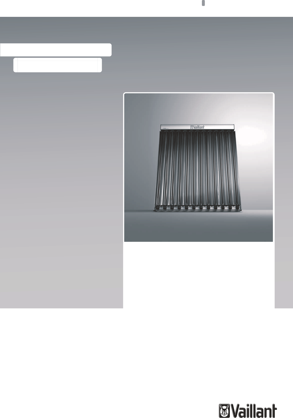
0020077994_02 auroTHERM exclusive Installation manual 3
Contents
1 Notes on the documentation.............................. 5
1.1 Symbols used................................................................. 5
1.2 Observing other applicable documents .................. 5
1.3 Document storage........................................................ 5
1.4 Applicability of the instructions................................ 5
1.5 Name................................................................................ 5
2 Safety.................................................................... 6
2.1 Action-related warnings.............................................. 6
2.2 Required personnel qualifications............................ 6
2.2.1 Authorised competent person................................... 6
2.3 General safety information ........................................ 6
2.3.1 Danger due to improper use ...................................... 6
2.3.2 Risk of death due to improper fastening
systems ........................................................................... 6
2.3.3 Risk of death due to inadequate load-bearing
capacity of the roof...................................................... 6
2.3.4 Risk of death due to falling parts.............................. 6
2.3.5 Risk of injury and material damage due to
incorrect maintenance and repairs.......................... 6
2.3.6 Risk of death due to inadequate fastening of
the collectors................................................................. 7
2.3.7 Risk of burns due to hot collector surfaces ........... 7
2.3.8 Risk of injury due to breaking glass ......................... 7
2.3.9 Material damage caused by a high-pressure
cleaner............................................................................. 7
2.3.10 Material damage due to lightning............................. 7
2.3.11 Frost damage due to water in the solar circuit..... 7
2.3.12 Material damage due to an unsuitable tool............ 7
2.3.13 Risk of death from electric shock............................. 7
2.3.14 Material damage due to overvoltage....................... 7
2.3.15 Risk of death and material damage due to
contact corrosion.......................................................... 7
2.3.16 Material damage due to snow falling from
roofs................................................................................. 7
2.4 Intended use .................................................................. 8
2.4.1 Intended use .................................................................. 8
2.4.2 Suitability of the equipment....................................... 8
2.4.3 Improper use.................................................................. 8
2.4.4 Other applicable documents...................................... 8
2.5 Regulations (directives, laws, standards)............... 8
2.5.1 Installation regulations................................................ 8
2.5.2 Regulations for the prevention of accidents ......... 8
2.6 CE label............................................................................ 9
3 Description of the unit ....................................... 10
3.1 Type overview .............................................................. 10
3.2 Information on the identification plate .................. 10
3.3 Purpose of the unit...................................................... 10
4 On-roof fitting and installation .......................... 11
4.1 Preparing for fitting and installation ....................... 11
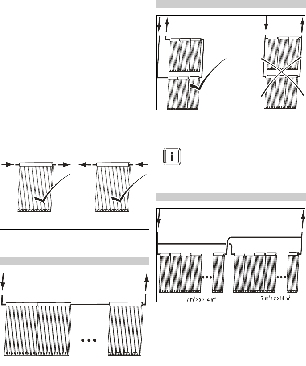
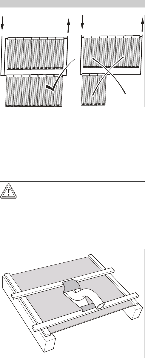
4.1.1 Delivery, transport and positioning.......................... 11
4.1.2 Complying with clearances and installation
clearances...................................................................... 14
4.1.3 Selecting suitable connection................................... 14
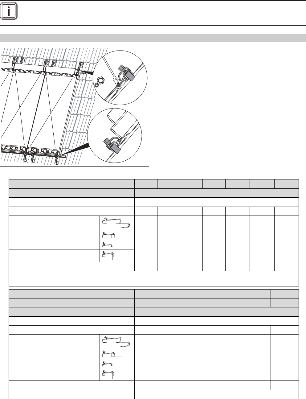
4.1.4 Preparing the roof duct.............................................. 15
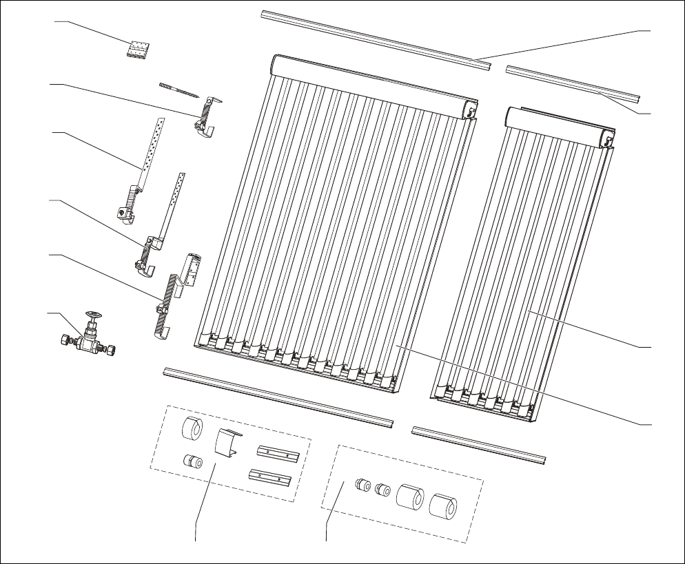
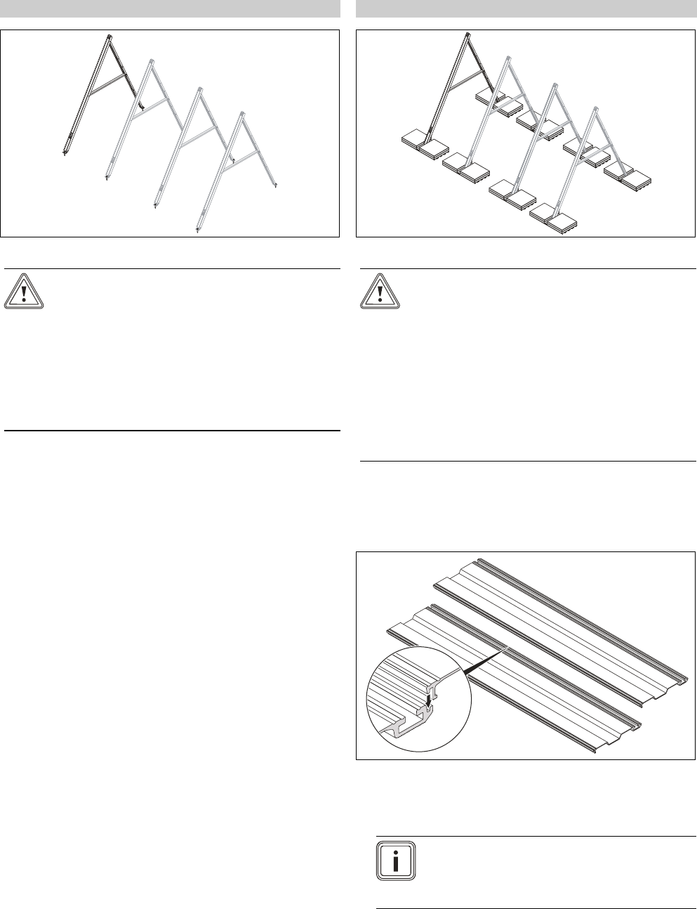
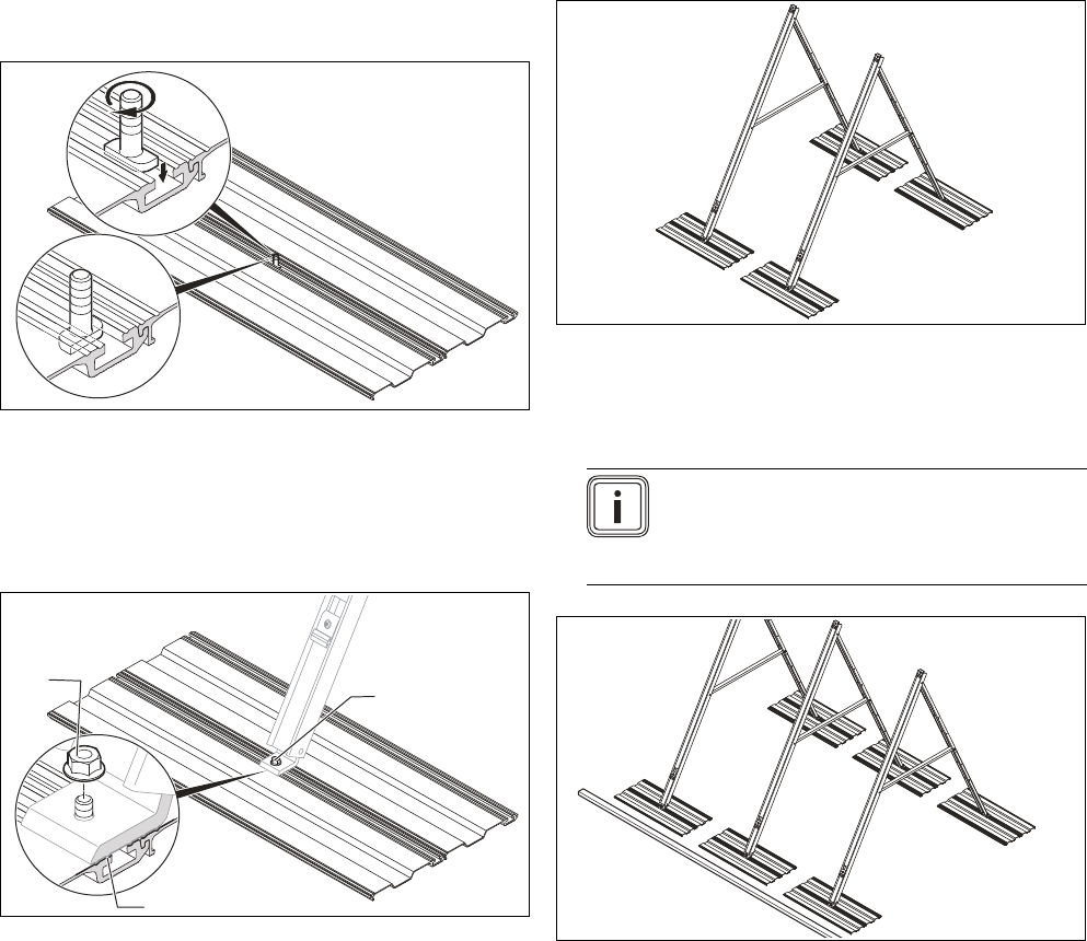
4.1.5 Putting together components .................................. 16
4.1.6 Determining the number of required roof
brackets.......................................................................... 19
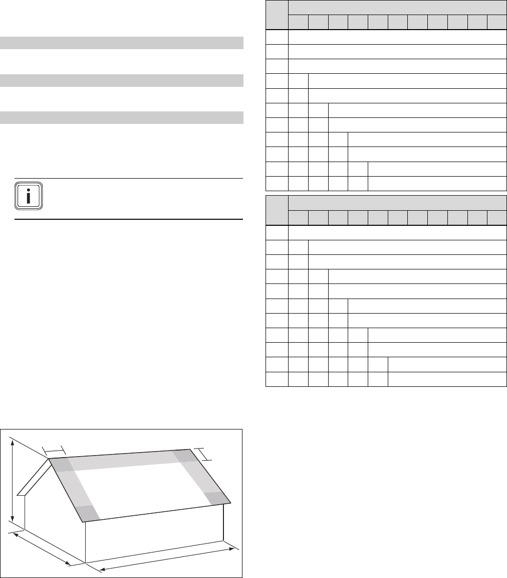
4.1.7 Defining the edge clearances of the roof
brackets.......................................................................... 19
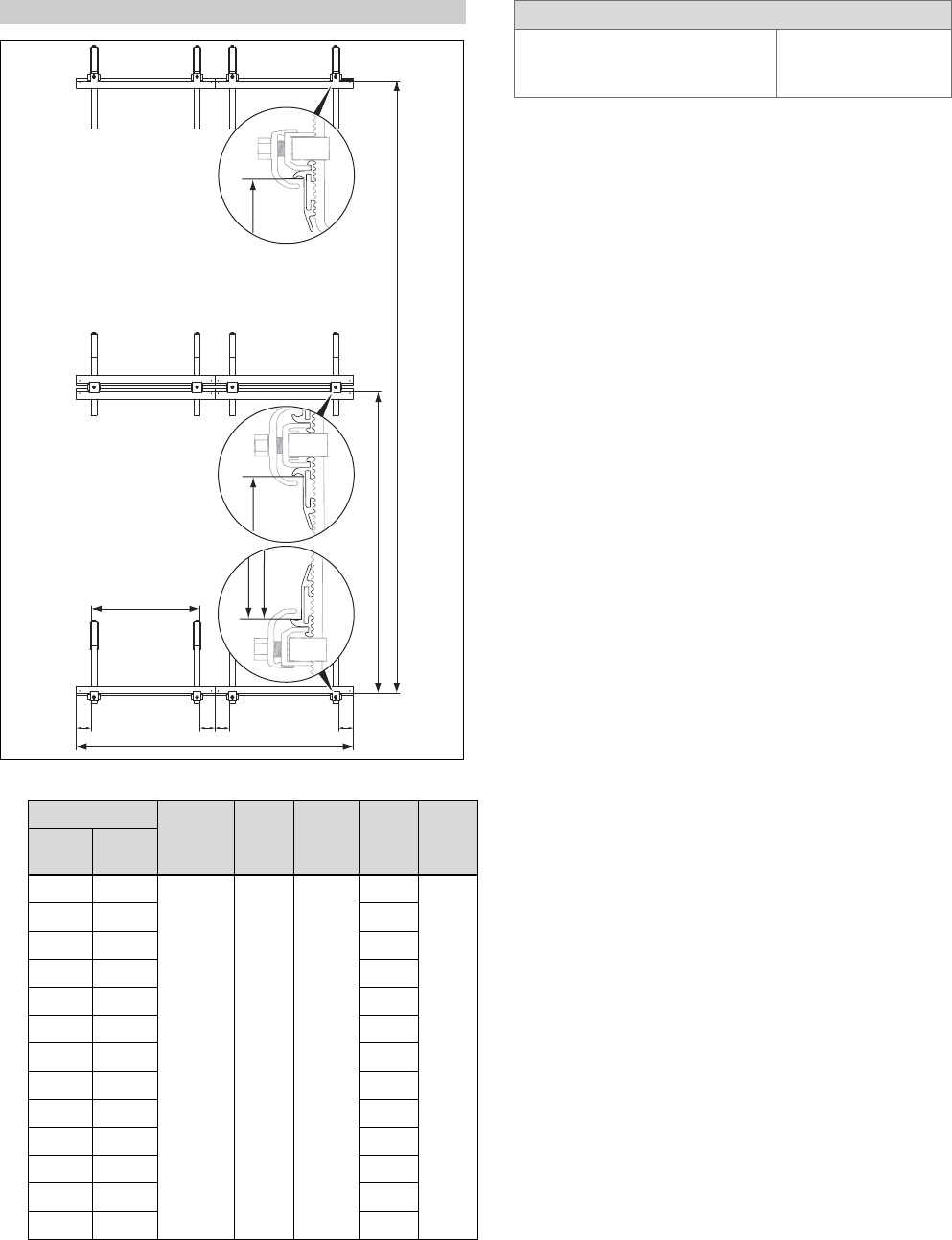
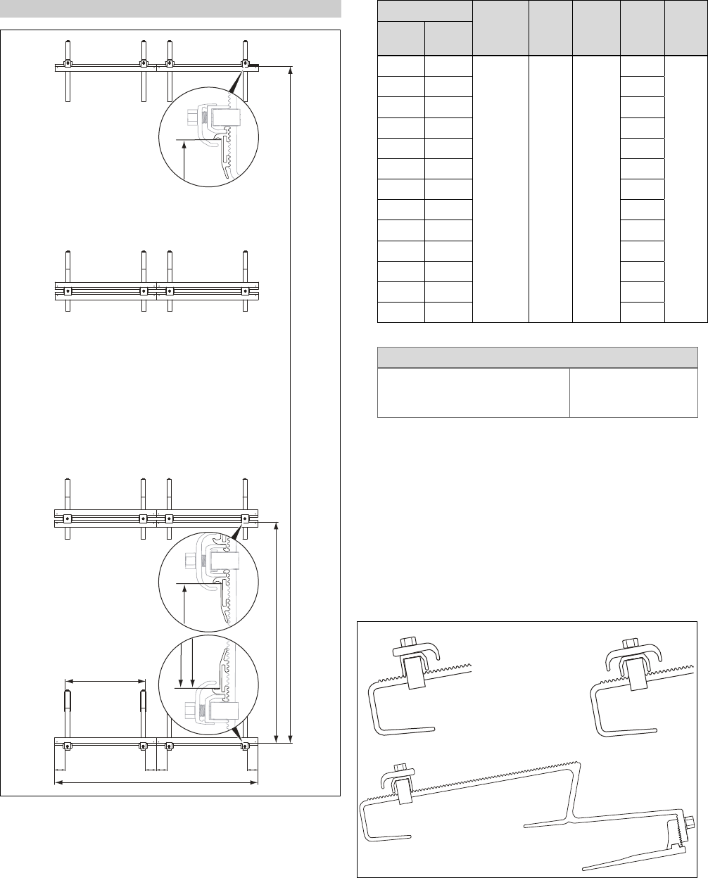
4.1.8 Defining the roof bracket clearances ..................... 19
4.2 Carrying out the installation.................................... 22
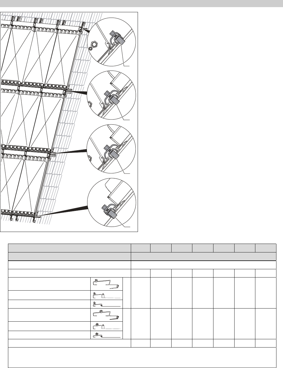
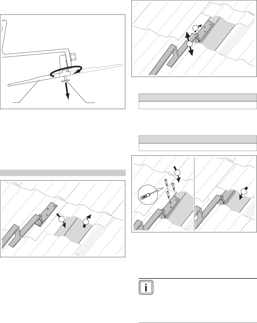
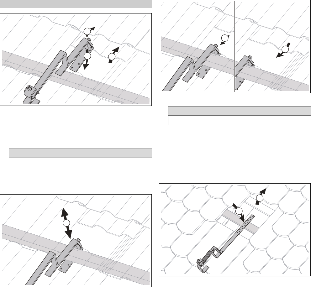
4.2.1 Installing roof brackets ............................................. 22
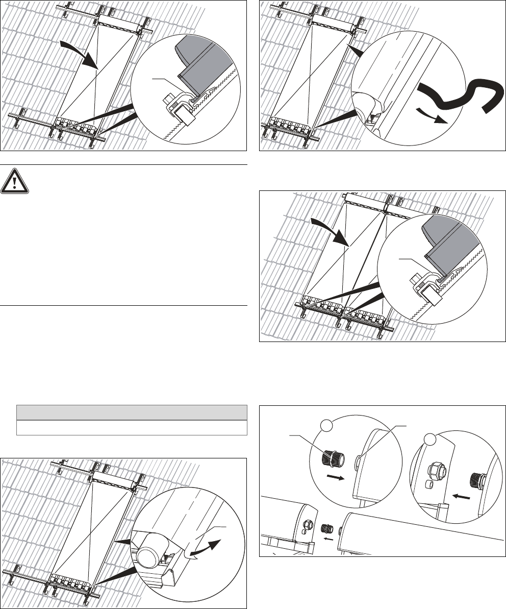
4.2.2 Installing collectors .................................................... 26
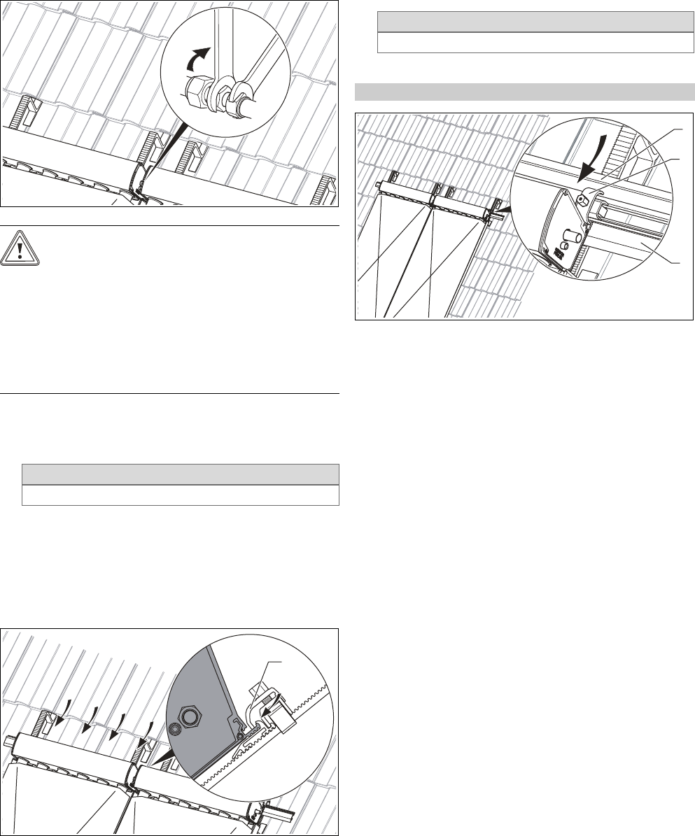
4.2.3 Installing hydraulic connections ............................. 29
4.3 Completing and checking the installation ............. 31
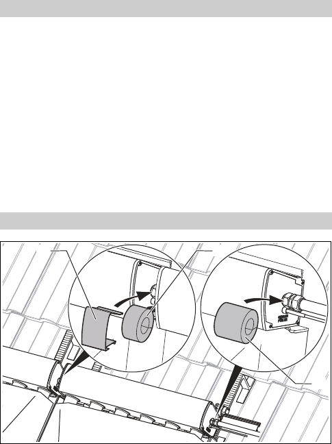
4.3.1 Checking installation................................................... 31
4.3.2 Disposing of the packaging ...................................... 32
5 Flat roof fitting and installation ...................... 33
5.1 Preparing for fitting and installation ..................... 33
5.1.1 Delivery, transport and positioning........................ 33
5.1.2 Complying with clearances and installation
clearances..................................................................... 35
5.1.3 Selecting suitable connection.................................. 35
5.1.4 Preparing the roof duct............................................. 36
5.1.5 Selecting the installation variant............................ 36
5.1.6 Putting together components ................................. 37
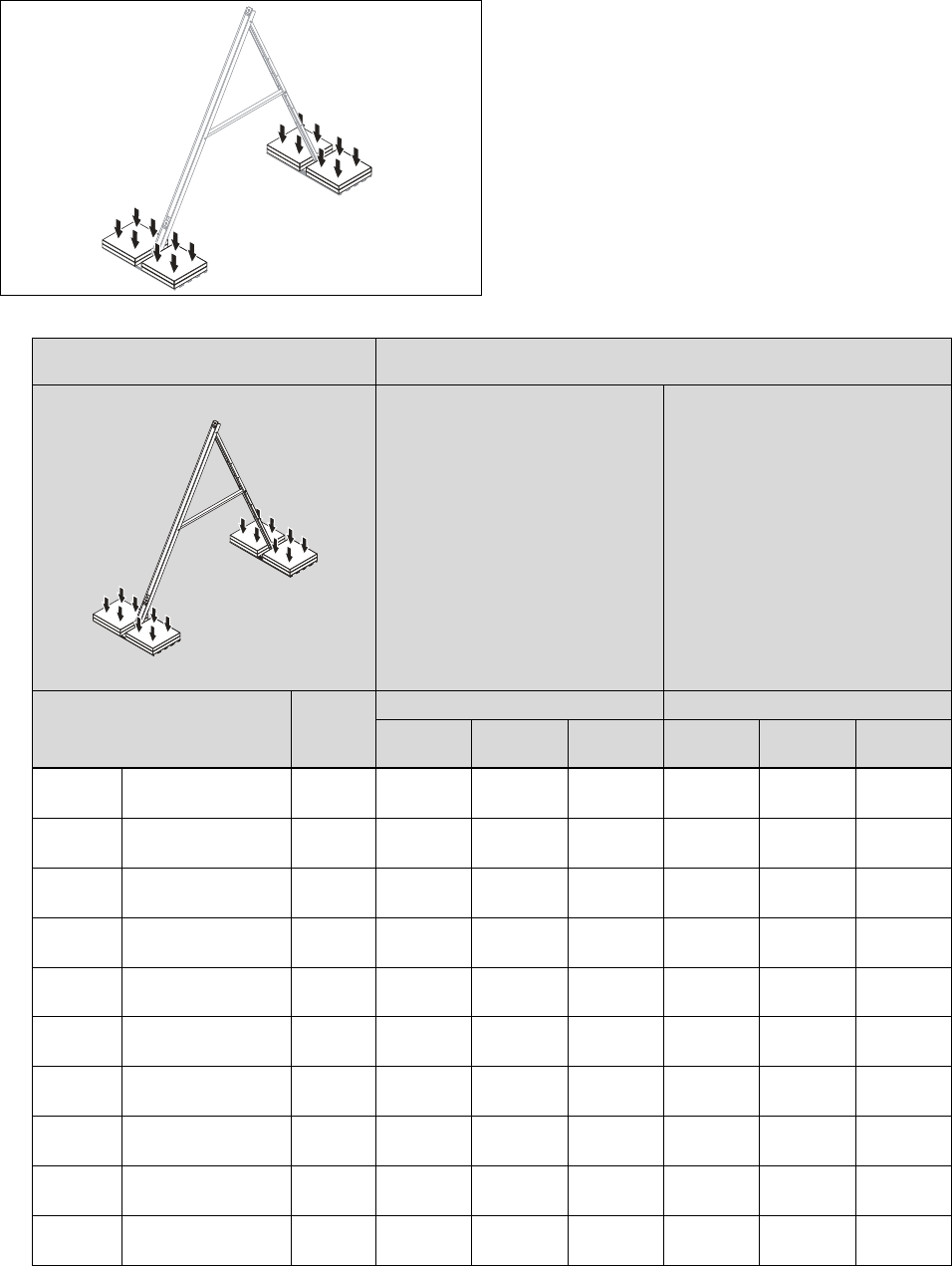
5.1.7 Determining the ballast load (floating
installation) .................................................................. 37
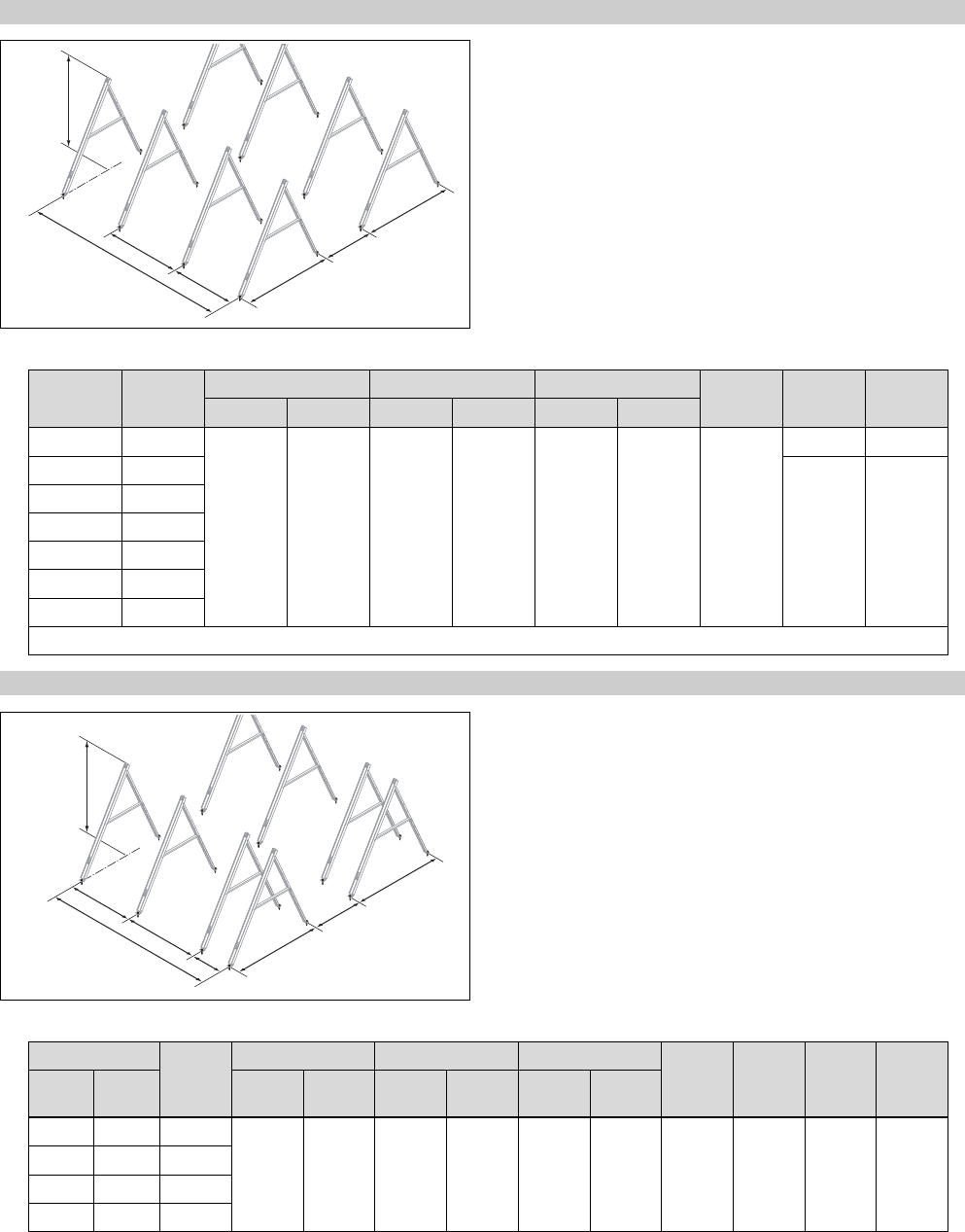
5.1.8 Defining the rack clearances .................................. 45