Contents
2 Installation instructions aroTHERM 0020147164_04
Contents
1 Safety .................................................................... 3
1.1 Action-related warnings ......................................... 3
1.2 Required personnel qualifications ......................... 3
1.3 General safety information .................................... 3
1.4 Regulations (directives, laws, standards) .............. 4
1.5 CE label ................................................................. 4
1.6 Approvals............................................................... 5
1.7 Local regulations.................................................... 5
1.8 Regulations............................................................ 5
1.9 Other regulations ................................................... 5
1.10 Intended use.......................................................... 6
2 Notes on the documentation .............................. 7
2.1 Observing other applicable documents ................. 7
2.2 Storing documents................................................. 7
2.3 Applicability of the instructions .............................. 7
3 System overview.................................................. 7
3.1 Safety devices ....................................................... 7
3.2 Design of the heat pump system........................... 7
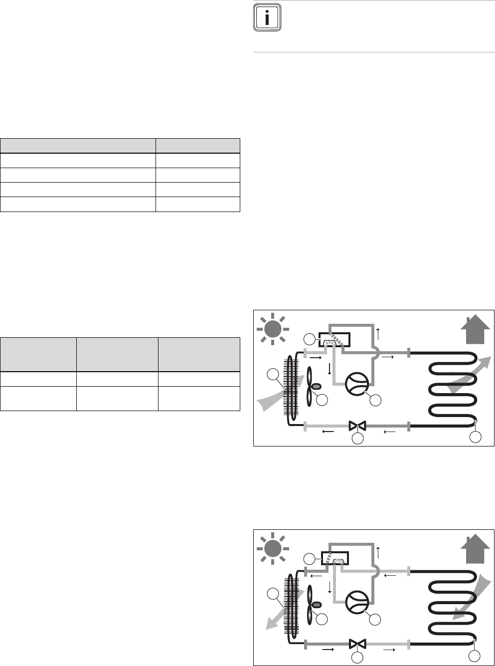
3.3 Functionality........................................................... 7
3.4 System diagram (VWL 55/2 A 230 V).................... 8
3.5 System diagram (VWL 85/2 A 230 V, VWL
115/2 A 230 V, VWL 155/2 A 230 V)..................... 8
4 Overview of the equipment................................. 9
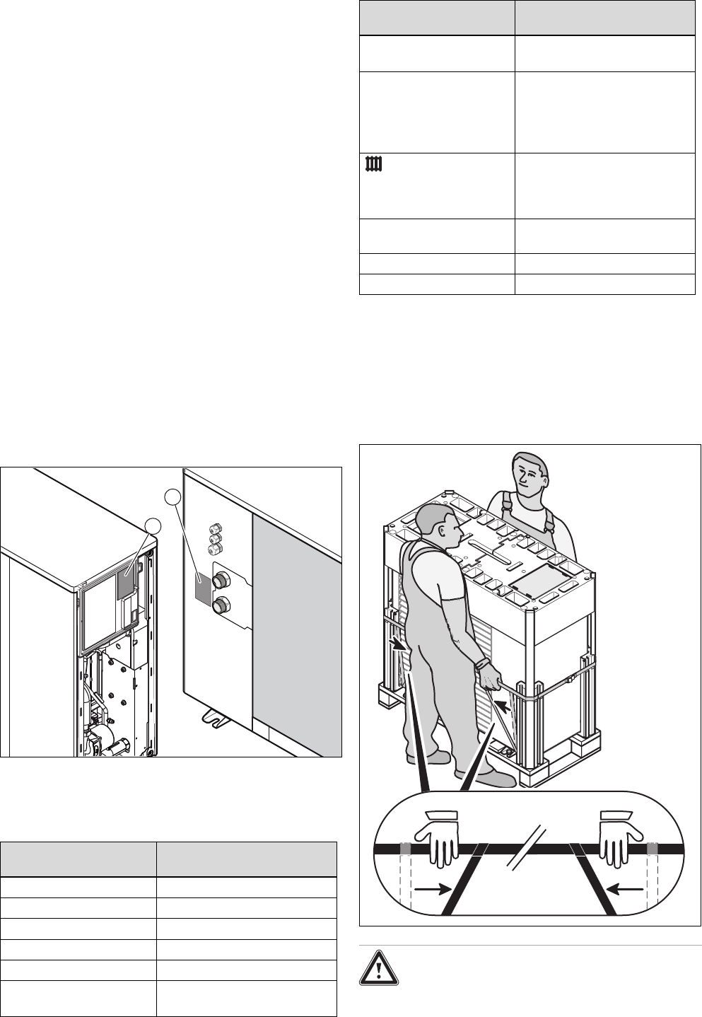
4.1 Type designation and serial number ..................... 9
4.2 Information on the identification plate.................... 9
5 Assembly and installation .................................. 9
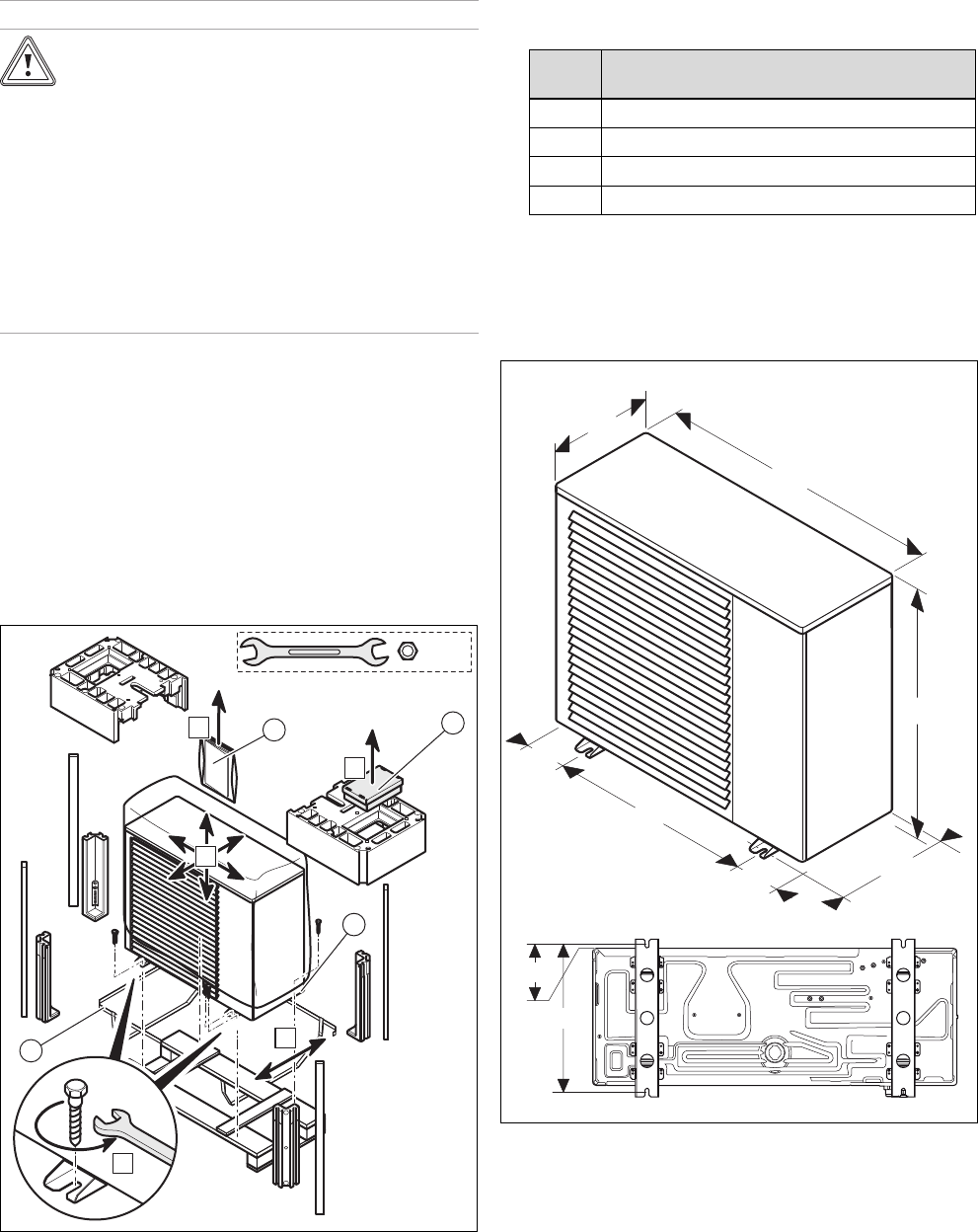
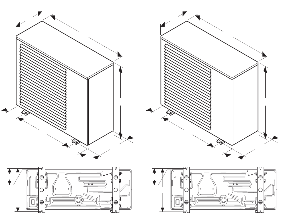
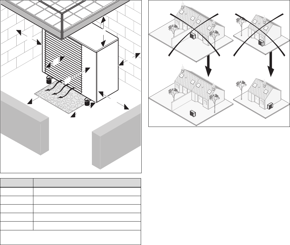
5.1 Preparing for fitting and installation ....................... 9
5.2 Carrying out the installation ................................. 14
5.3 Hydraulics installation.......................................... 14
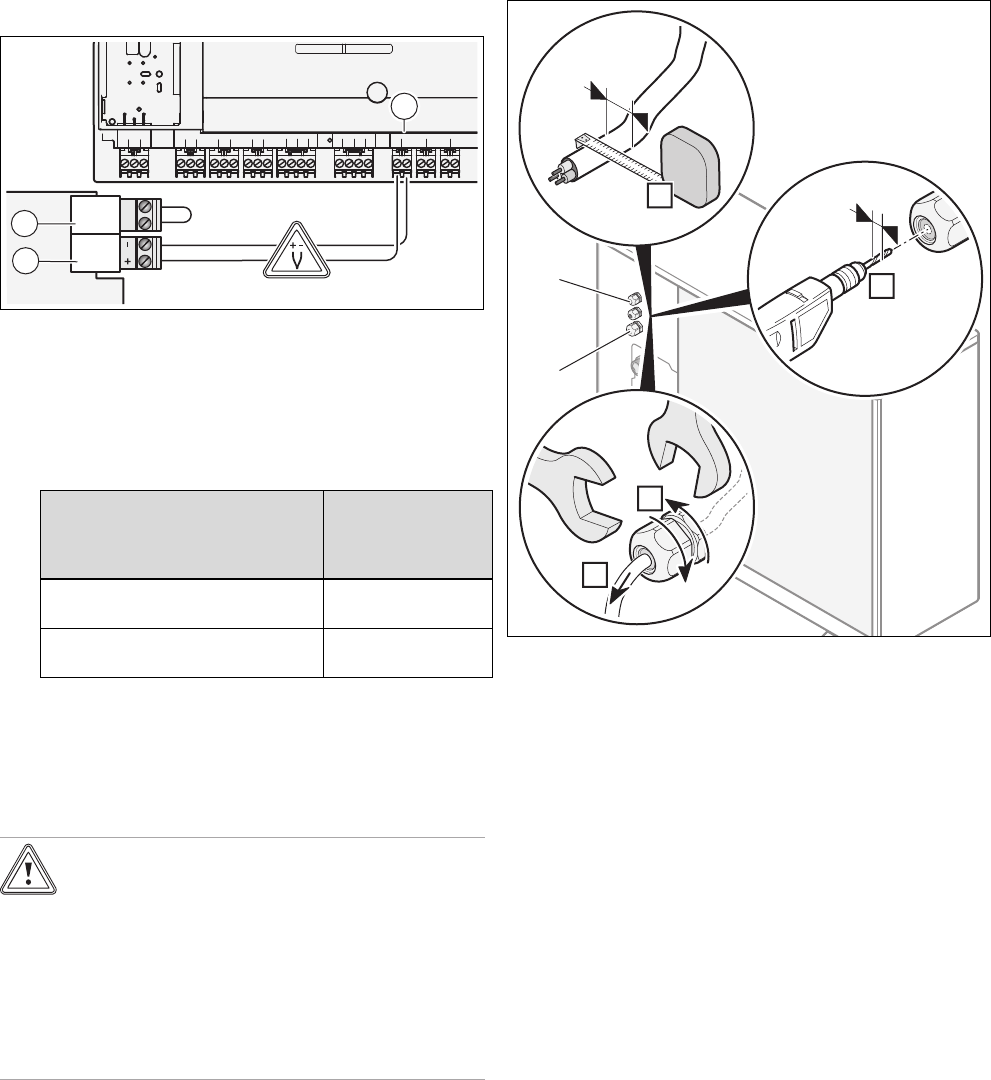
5.4 Carrying out the electrical installation.................. 17
5.5 Connection diagrams........................................... 19
6 Start-up ............................................................... 21
6.1 Run the start-up................................................... 21
6.2 Heat pump operating concept ............................. 21
6.3 Running through the installation assistant........... 21
6.4 Calling up Live Monitor (checking status
codes).................................................................. 21
6.5 Calling up statistics.............................................. 21
6.6 Filling the heating circuit ...................................... 21
6.7 Preparing the heating water ................................ 22
6.8 Filling the heating installation .............................. 23
6.9 Activating the heat pump ..................................... 23
6.10 Checking the product's operation ........................ 23
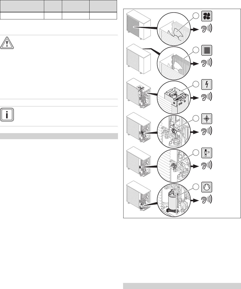
6.11 Operating noises.................................................. 23
6.12 Adjusting the heating circuit................................. 23
6.13 Installing the side cladding .................................. 25
6.14 Instructing the operator........................................ 25
7 Maintenance....................................................... 25
7.1 Observing maintenance intervals ........................ 25
7.2 Preparing for maintenance .................................. 25
7.3 Instructions before carrying out maintenance
work ..................................................................... 25
7.4 Yearly maintenance............................................. 25
7.5 Cleaning the product............................................ 26
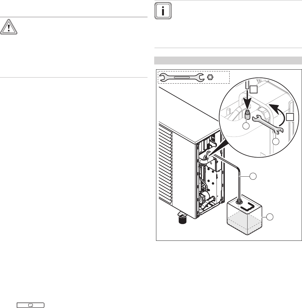
7.6 Draining the product ............................................ 26
7.7 Checking the product's status codes................... 27
7.8 Checking the electrical installation ...................... 27
7.9 Start-up following maintenance ........................... 27
8 Troubleshooting ................................................ 27
8.1 Troubleshooting................................................... 27
8.2 Fault codes .......................................................... 27
8.3 Carrying out the actuator test .............................. 27
9 Decommissioning.............................................. 28
9.1 Temporary decommissioning .............................. 28
9.2 Permanently decommissioning............................ 28
10 Vaillant customer service ................................. 28
10.1 Customer service................................................. 28
11 Disposal.............................................................. 28
11.1 Recycling and disposal........................................ 28
11.2 Arranging disposal of coolant .............................. 28
Appendix ............................................................................ 29
A Overview of accessories................................... 29
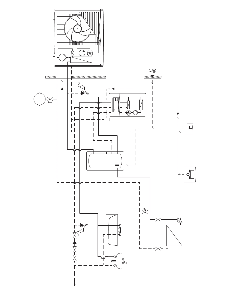
B System diagrams............................................... 30
B.1 System diagram 8 E ............................................ 30
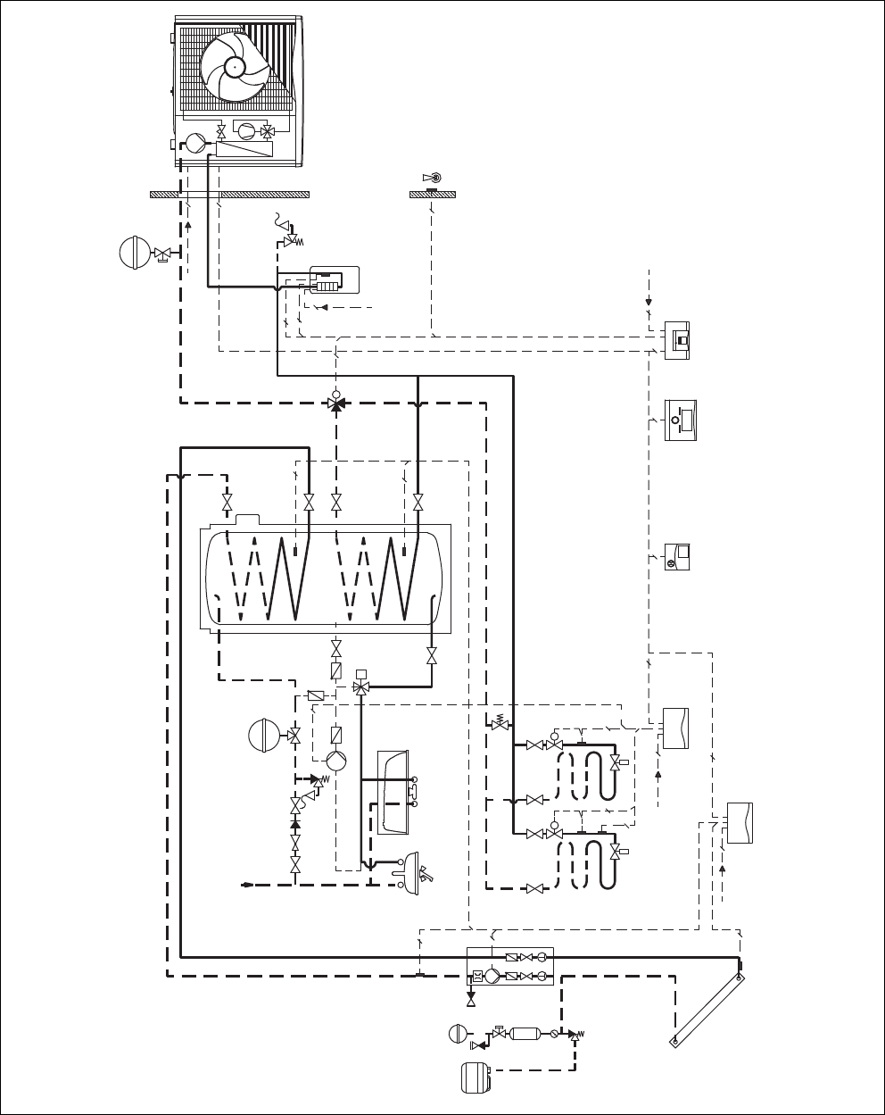
B.2 System diagram 8 F............................................. 32
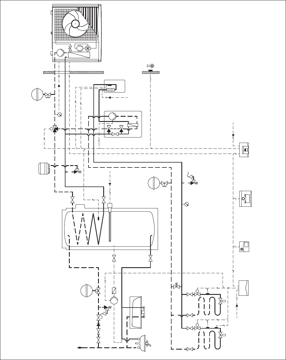
B.3 System diagram 10 B .......................................... 34
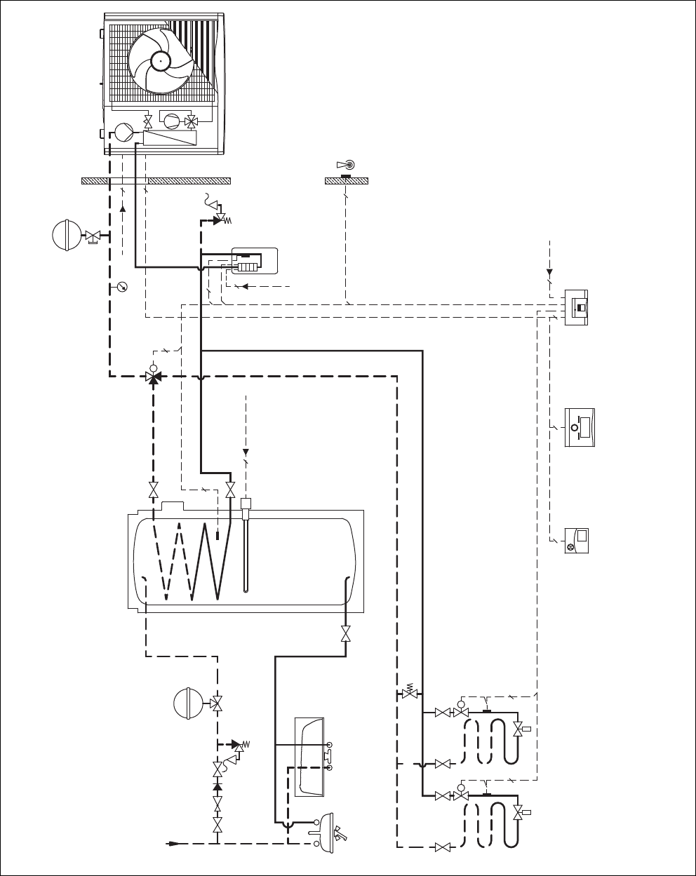
B.4 System diagram 12 A .......................................... 36
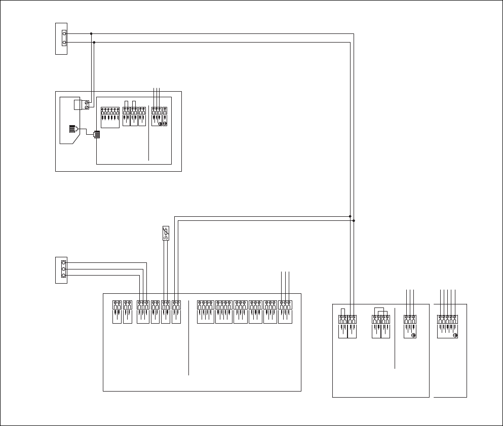
C Wiring diagrams................................................. 37
C.1 Wiring diagram 8 E .............................................. 37
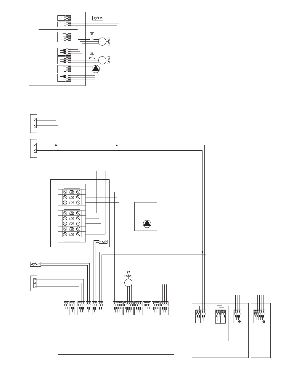
C.2 Wiring diagram 8 F .............................................. 38
C.3 Wiring diagram 10 B ............................................ 39
C.4 Wiring diagram 12 A ............................................ 40
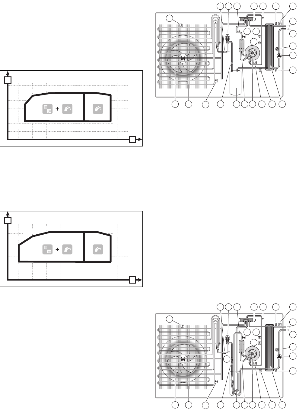
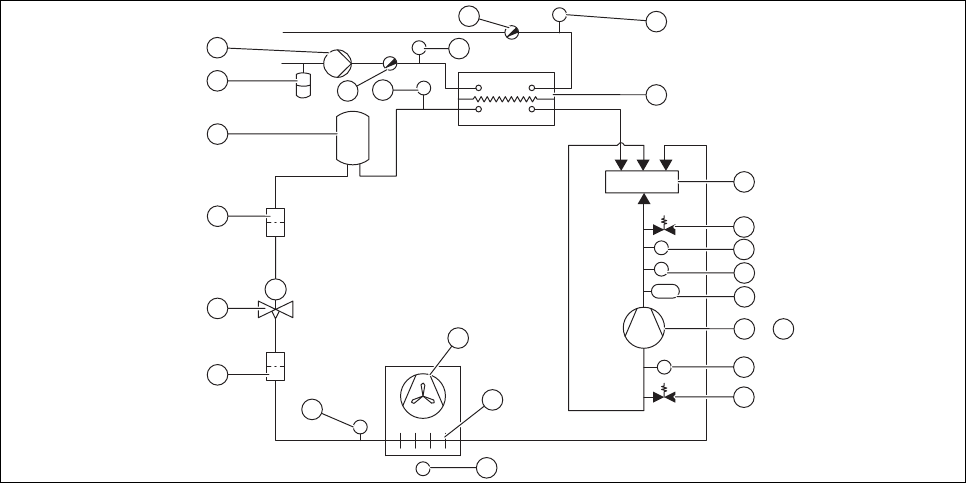
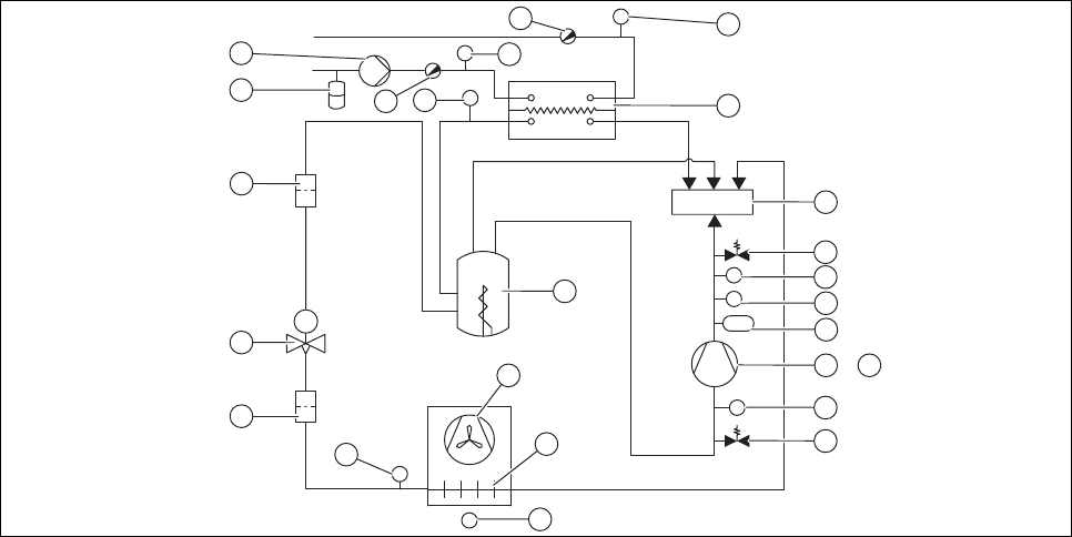
D Heat pump schematic........................................ 41
D.1 Heat pump schematic drawing (VWL 55/2 A
230 V) .................................................................. 41
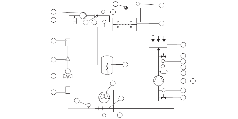
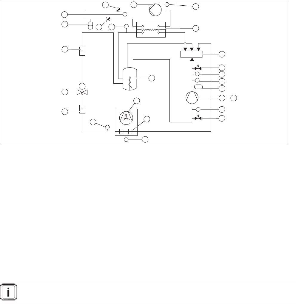
D.2 Heat pump schematic drawing (VWL 85/2 A
230 V) .................................................................. 42
D.3 Heat pump schematic drawing (VWL 115/2 A
230 V) .................................................................. 43
D.4 Heat pump schematic drawing (VWL 155/2 A
230 V) .................................................................. 44
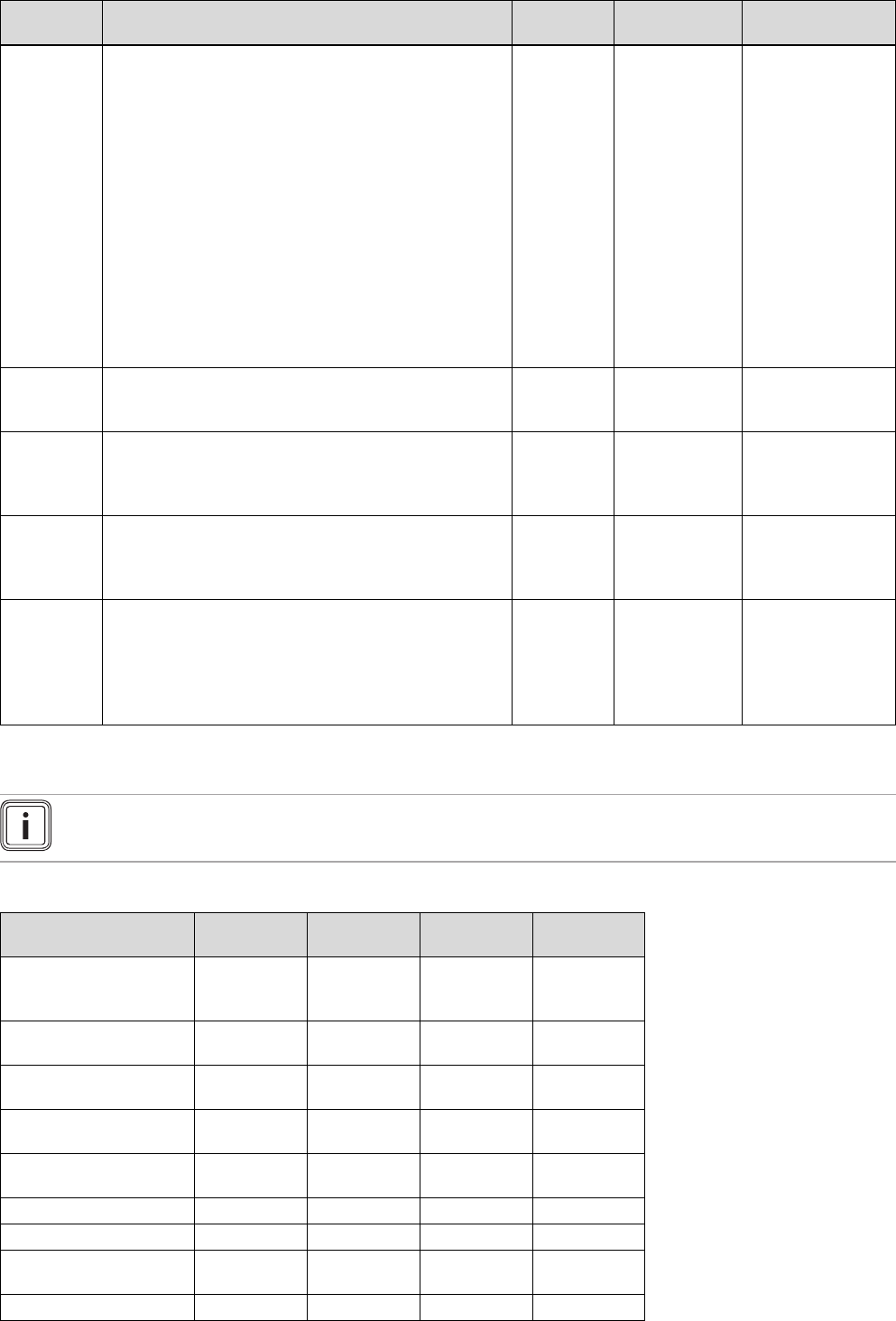
E Heat pump setting parameters......................... 44
F Technical data.................................................... 45
G Overview of fault codes .................................... 48
Index ................................................................................... 51