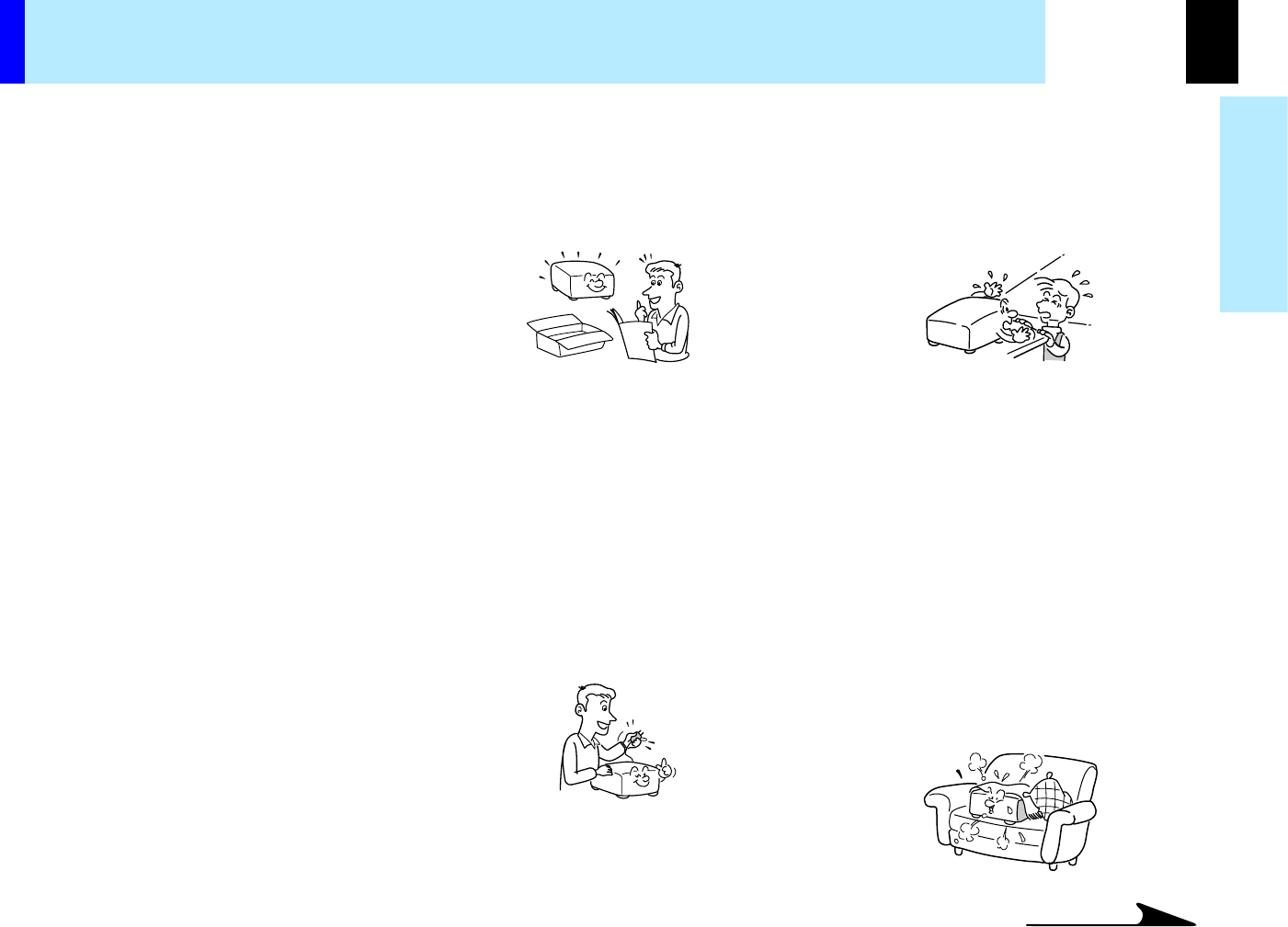
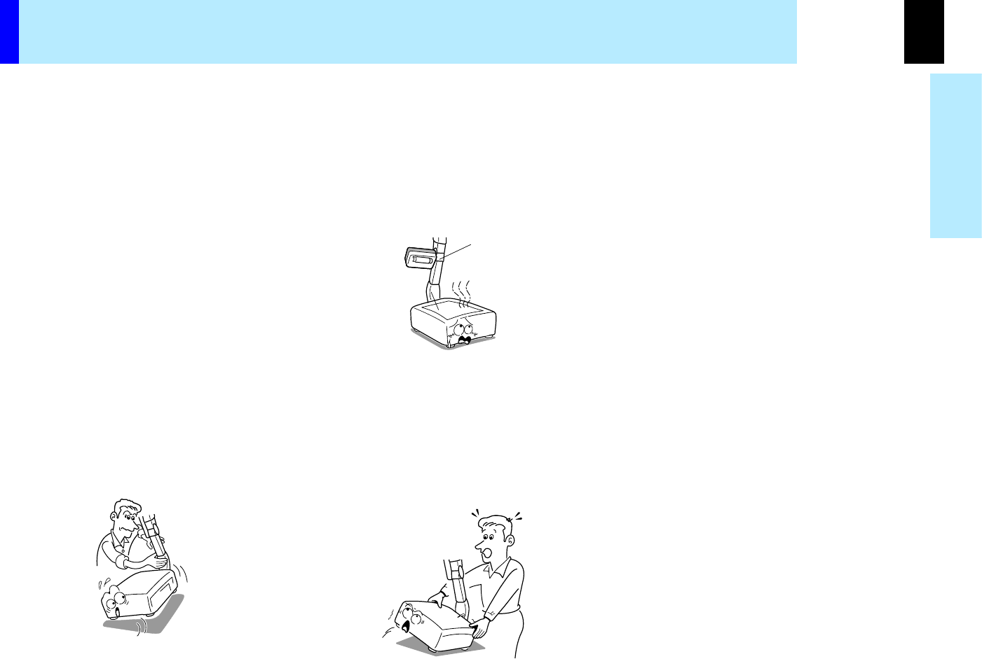
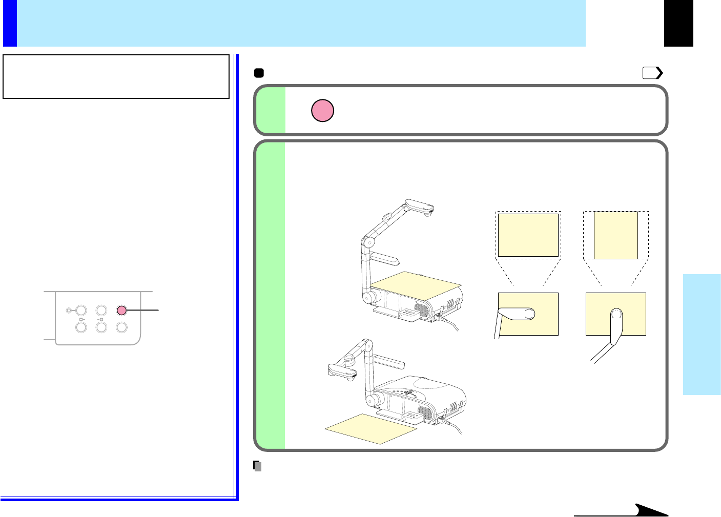
•The air exhaust discharges high temperature air. Do not put something around the air exhaust, otherwise it may be deformed by the high temperature air.
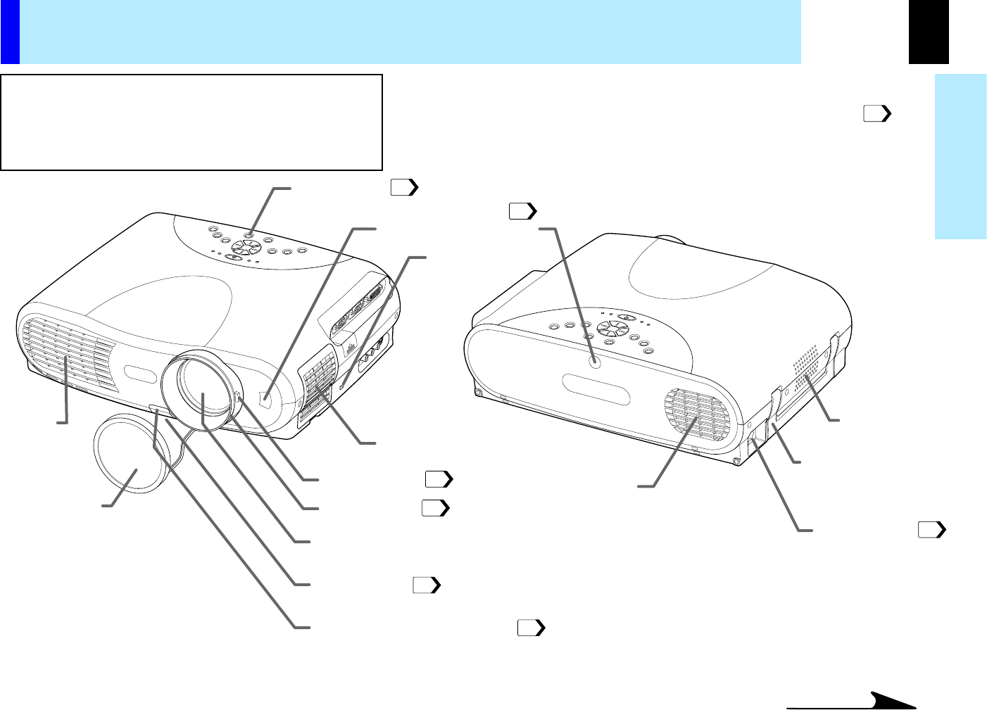
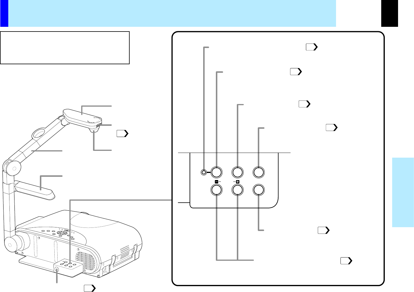
Names of each part on the main unit
CAUTION
Openings in the cabinet are provided for ventilation and
to ensure reliable operation of the product and to protect
it from overheating, and these openings must not be
blocked or covered.
Continued
The explanation here is only for the model not with the document imaging
camera. For the model with the document imaging camera, refer to .
12
16
19
31
20
20
54
31
CONTENTS
12
Before use
K
E
Y
S
T
O
N
E
A
U
T
O
S
E
T
E
X
I
T
ON / STANDBY
VOL / ADJ
E
N
T
E
R
M
E
N
U
I
N
P
U
T
F
A
N
T
E
M
P
L
A
M
P
O
N
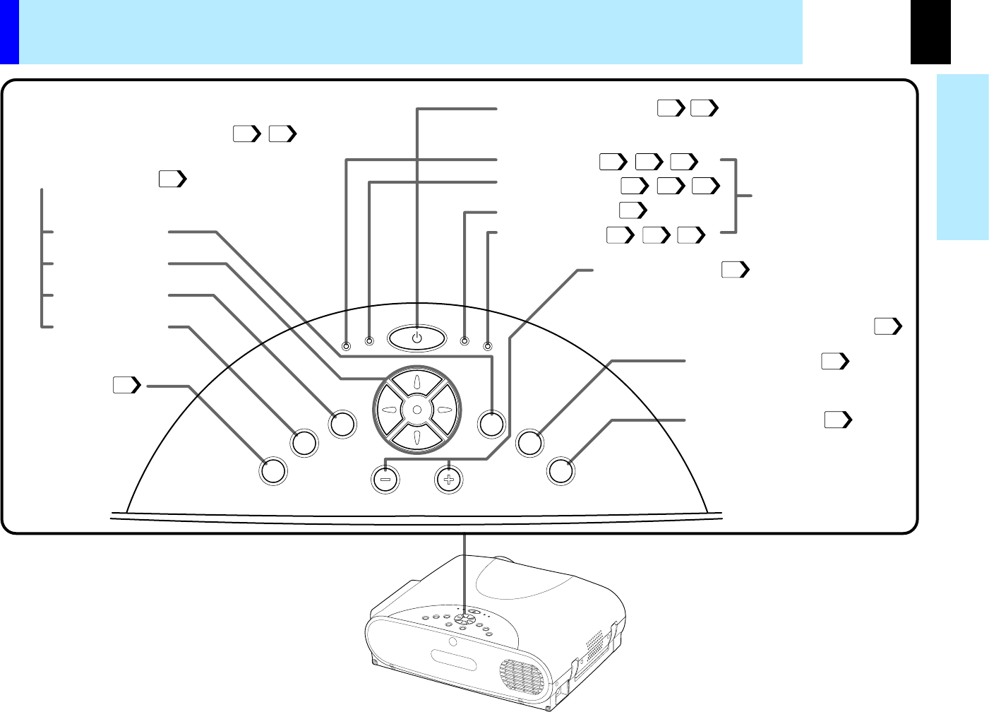
KEYSTONE button
To correct the keystone distortion of
the picture.
AUTO SET button
To adjust the image of the Computer
input automatically.
VOL/ADJ button
To set and/or adjust values on the menu.
To adjust volume when the menu is not displayed.
ENTER button
Selection button
EXIT button
MENU button
ON/STANDBY button
To turn the projector on or off (standby).
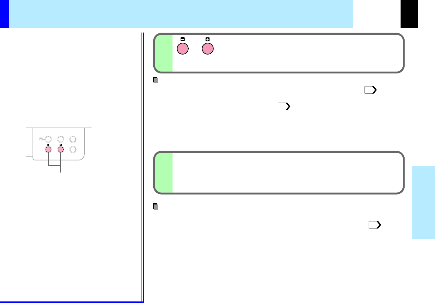
INPUT button
To select the input
source.
To display the menu screen and/or select the
operation on the menu screen.
Use the selection button and EXIT button to
enlarge the image.
To indicate the status of
the projector.
FAN indicator
ON indicator
LAMP indicator
TEMP indicator
Names of each part on the main unit (continued)
Top side
Control panel
34
44
32
43
39
30
2833
2833
2833
28
33
62
35
44
62
62
62
CONTENTS
13
Before use
USB
COMPUTER IN 1
COMPUTER IN 2
S-VIDEOVIDEO
VIDEO IN
R - AUDIO - L
AUDIO
IN
(
Y/P
B
/P
R
)
MONITOR
OUT
CONTROL
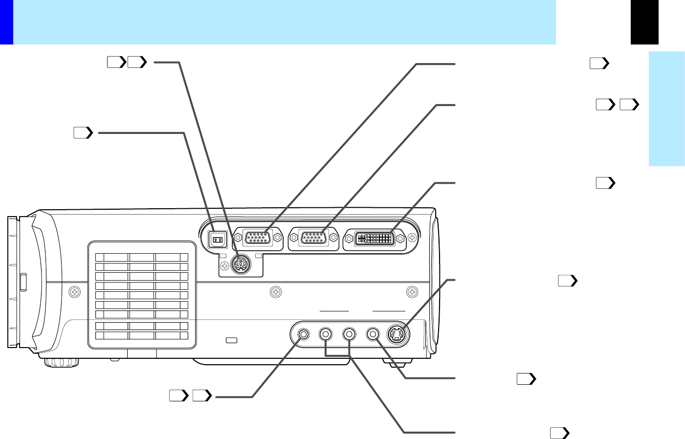
COMPUTER IN 1connector
To enter RGB signal from a computer,
etc or component video signal (Y/PB/PR
Signal) from a video equipment.
S-VIDEO connector
To enter S-Video signal from a video
equipment, etc.
VIDEO jack
To enter video signal from a video
equipment, etc.
AUDIO(L/R) jacks
To enter audio signal from a video
equipment, etc.
AUDIO IN jack (Audio input)
(
φ
3.5mm stereo mini-jack)
To enter audio signal from a computer or a video
equipment with component video output (Y/PB/PR
signal output) supported.
CONTROL connector
(RS-232C connector)
To connect a computer to control the
projector. (Remove the cover when using
the connector.)
MONITOR OUTconnector
To connect a monitor, etc.
COMPUTER IN 2connector
To enter RGB signal from a computer,
etc.
USB connector
To connect to a USB connector of a
computer when using the remote control
mouse.
Names of each part on the main unit (continued)
Right side
27
23
42
26
2225
24
24
24
2225
73
CONTENTS
14
Before use
MENU
ON/STANDBY
LASER
INPUT
L-CLICKR-CLICK
ENTER
KEYSTONE
AUTO
SET
EXIT
PIP
FREEZE
MUTECALL
RESIZE
VOLUME/ADJUST
AVOID
EXPOSURE LASER
MENU
ON/STANDBY
LASER
INPUT
L-CLICKR-CLICK
ENTER
KEYSTONE
AUTO
SET
EXIT
PIP
FREEZE
MUTECALL
RESIZE
VOLUME/ADJUST
LASER RADIATION
DO NOT STARE INTO BEAM, CLASS 2 LASER PRODUCT
LASER-STRAHLUNG
NICHT
IN
DEN
STRAHL
BLICKEN,
LASER
KLASSE
2
PRODUKT
RAYONNEMENT
LASER
NE
PAS
REGARDER
DANS
LE
FAISCEAU
APPAREIL
A
LASER
DE
CLASSE
2
WAVE
LENGTH (WELLENÄNGE,
LONGUEUR
D' ONDE) : 650nm
MAX
OUTPUT
(MAX AUSGANGSLEISTUNG,
PUISSANCE
MAXIMA) : 1mW
LASER RADIATION
DO NOT STARE INTO BEAM
WAVE LENGTH:650nm
MAX OUTPUT:1mW
CLASS II LASER PRODUCT
COMPLIES WITH DHHS 21 CFR SUBCHAPTER J
TOSHIBA AMERICA CONSUMER PRODUCTS,INC.
82 TOTOWA RD., WAYNE, NJ 07470, U.S.A.
MANUFACTURED:
SEPTEMBER 2000
PLACE OF
MANUFACTURE:A
IEC60825-1 A1;1997
REMOTECONTROLMODELCT–90057
CAUTION
RADIATION IS EMITTED
FROM THIS APERTURE
MADE IN JAPAN
LASER RADIATION
DO NOT STARE INTO BEAM, CLASS 2 LASER PRODUCT
LASER-STRAHLUNG
NICHT
IN
DEN
STRAHL
BLICKEN,
LASER
KLASSE
2
PRODUKT
RAYONNEMENT
LASER
NE
PAS
REGARDER
DANS
LE
FAISCEAU
APPAREIL
A
LASER
DE
CLASSE
2
WAVE
LENGTH (WELLENÄNGE,
LONGUEUR
D' ONDE) : 650nm
MAX
OUTPUT
(MAX AUSGANGSLEISTUNG,
PUISSANCE
MAXIMA) : 1mW
LASER RADIATION
DO NOT STARE INTO BEAM
WAVE LENGTH:650nm
MAX OUTPUT:1mW
CLASS II LASER PRODUCT
COMPLIES WITH DHHS 21 CFR SUBCHAPTER J
TOSHIBA AMERICA CONSUMER PRODUCTS,INC.
82 TOTOWA RD., WAYNE, NJ 07470, U.S.A.
MANUFACTURED:
SEPTEMBER 2000
PLACE OF
MANUFACTURE:A
IEC60825-1 A1;1997
REMOTECONTROLMODELCT –90057
CAUTION
AVOID
RADIATION IS EMITTED
FROM THIS APERTURE
MADE IN JAPAN
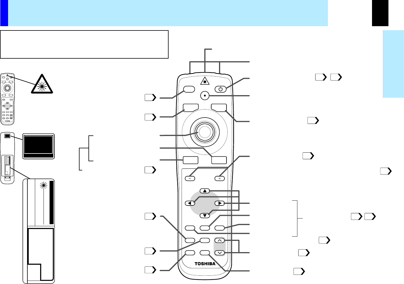
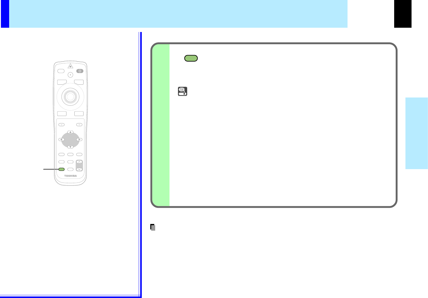
Remote control transmission part
ON/STANDBY button
To turn the projector on or off (standby).
AUTO SET button
To adjust the image of the Computer input
automatically.
RESIZE button
To enlarge the picture size.
CALL button
To display the information.
MENU button
Selection button
EXIT button
FREEZE button
To freeze the picture.
INPUT button
To select the input source.
KEYSTONE button
To correct the keystone
distortion of the picture
PIP button
To display the video input
image as a small size
picture in the computer
image display window.
VOL/ADJ button
To set and/or adjust values on the menu.
To adjust volume when the menu is not displayed.
Hereafter called "VOL/ADJ button" in this manual.
ENTER button
MUTE button
To cut off the picture and sound temporarily.
To display the menu screen
and/or select the operation on
the menu screen.
Use the selection button and
EXIT button to enlarge the im-
age.
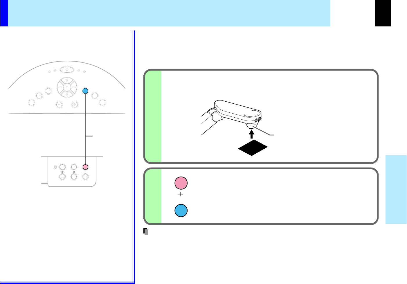
LASER button
To display the laser pointer by pointing the laser
emission part toward the screen.
Laser emission part
Pointer control button
R-CLICK button
L-CLICK button
To use as
USB remote control mouse.
Names of each part on the remote control
Caution - use of controls or adjustments or
performance of procedures other than those specified
herein may result in hazardous radiation exposure.
Location of the labels
REAR
30
35
38
40
37
44
32
2833
34
39
41
44
39
42
43
CONTENTS
15
Before use
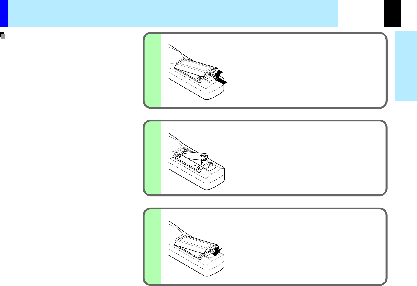
3
2
1
Using batteries incorrectly can cause them to leak or
burst. Strictly observe the following.
•Install the batteries with their + and - ends
facingcorrectly.
•Do not charge, heat, disassemble, or short the
batteries or throw them into a fire.
•Do not leave exhausted batteries in the remote
control.
•Do not mix different types of batteries or new and
old batteries.
•When you will not be using the remote control for
a prolonged period, take the batteries out of the
remote control.
•When the remote control stops working or only
works from very close distance, replace all the
batteries with new ones.
•When replacing the batteries, use a more longer
life alkaline batteries.
•If a battery leaks, carefully wipe off any residue
inside the battery case before loading new batteries.
Loading batteries
(Bottom Side)
Open the cover
Install the batteries
Make sure that the +/- polarities match the illustration in
the compartment.
Attach the cover
Notes
CONTENTS
16
Before use
RESIZE
MENU
PIP
FREEZE
MUTE
CALL
ON/STANDBY
LASER
INPUT
ENTER
AUTO
EXIT
VOLUME/ADJUST
SET
R-CLICK
L-CLICK
KEYSTONE
About 15
°
About 15
°
About 15
°
About 5m
About 15
°
RESIZE
MENU
PIP
FREEZE
MUTE
CALL
ON/STANDBY
LASER
INPUT
ENTER
AUTO
EXIT
VOLUME/ADJUST
SET
R-CLICK
L-CLICK
KEYSTONE
About 15
°
About 15
°
About 15
°
About 5m
About 15
°
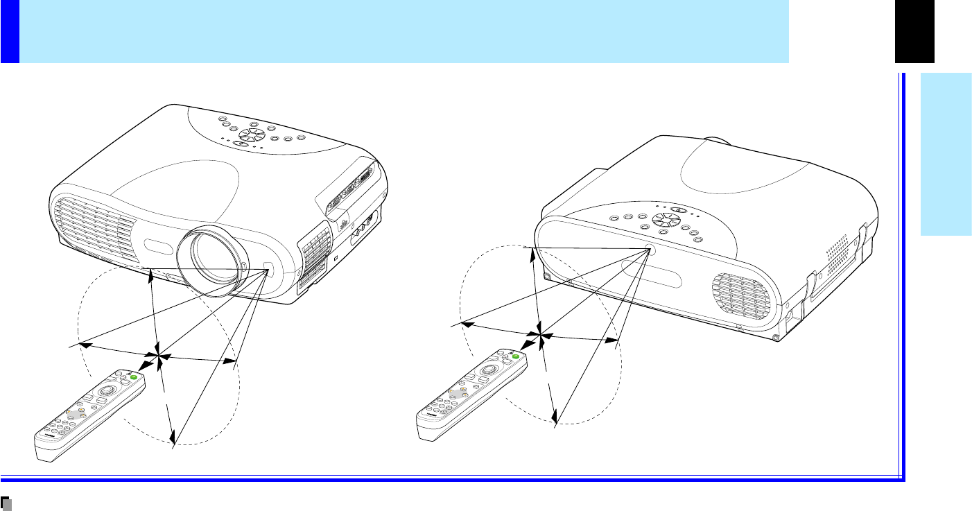
Remote control operation
Point the remote control at the infrared remote sensor and press a button.
•
The remote control may not operate when there is sunlight or other strong light such as a fluorescent lamp shining on the remote sensor.
•Operate the remote control from a position where the remote sensor is visible.
•Do not drop the remote control or otherwise jolt it.
•Keep the remote control out of locations with excessively high temperature or humidity.
•Do not get water on the remote control or place wet objects on it.
•Do not disassemble the remote control.
•Under unusual circumstances the remote control may not operate well due to the location being used or the surroundings.
At such times, change the direction of the remote control to the projector and retry the operation.
Rear side
Front side
Notes
CONTENTS
17
Installation and
connection
Continued
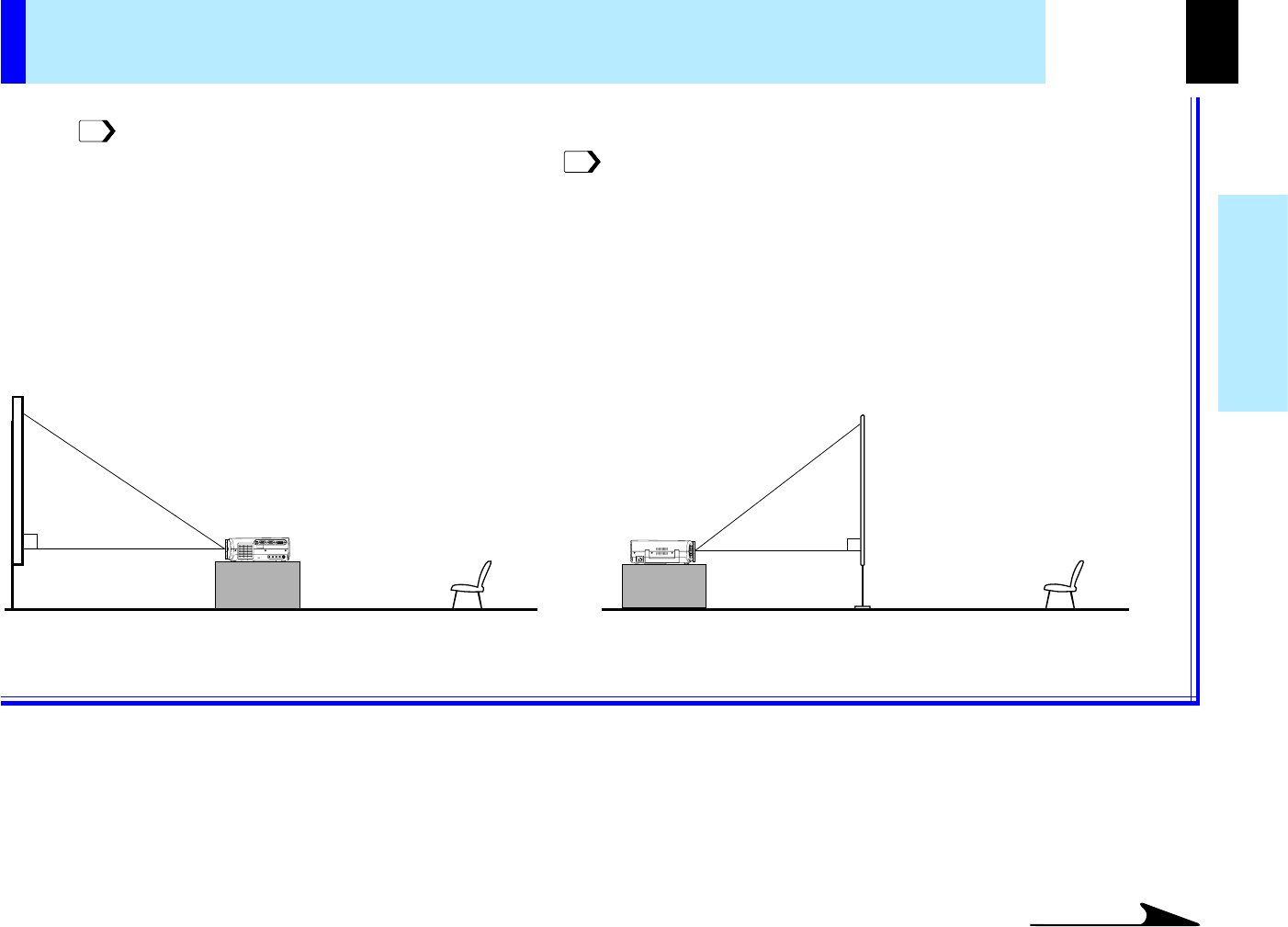
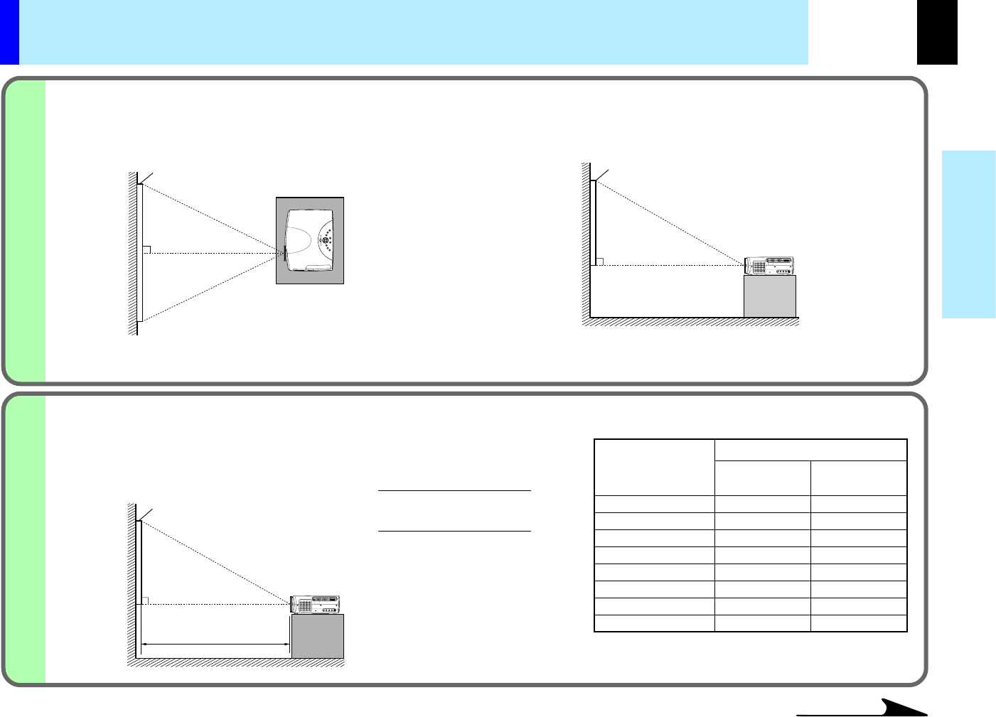
Floor-mounted projector placement
There are two ways to place the floor-mounted projector. Perform the "Projection mode" setting on the menu screen for the projection
method.
For the ceiling-mounted projector placement, refer to the page .
Floor-mounted front projection
Viewing a picture projected on the front of the screen from a floor
installation.
Floor-mounted rear projection
Viewing a picture projected through the back of the screen from a
floor installation.
Translucent screen
ViewerViewer
51
21
CONTENTS
18
Installation and
connection
2
1
32
40
60
80
100
150
200
300
-
1.42
2.16
2.90
3.63
5.48
7.33
11.02
1.42
1.80
2.74
3.67
4.60
6.93
9.26
-
a(m)
90°
a
90°
90°
Continued
Floor-mounted projector placement (continued)
Place the projector on a steady, level surface such as a table.
To obtain proper screen projected, place the projector so that the projecting light hits the screen squarely.
Top view
Screen
Side view
Screen
Point the lens straight at the center of the screen as above.
Place the projector horizontally so that the projecting light
hits the screen squarely.
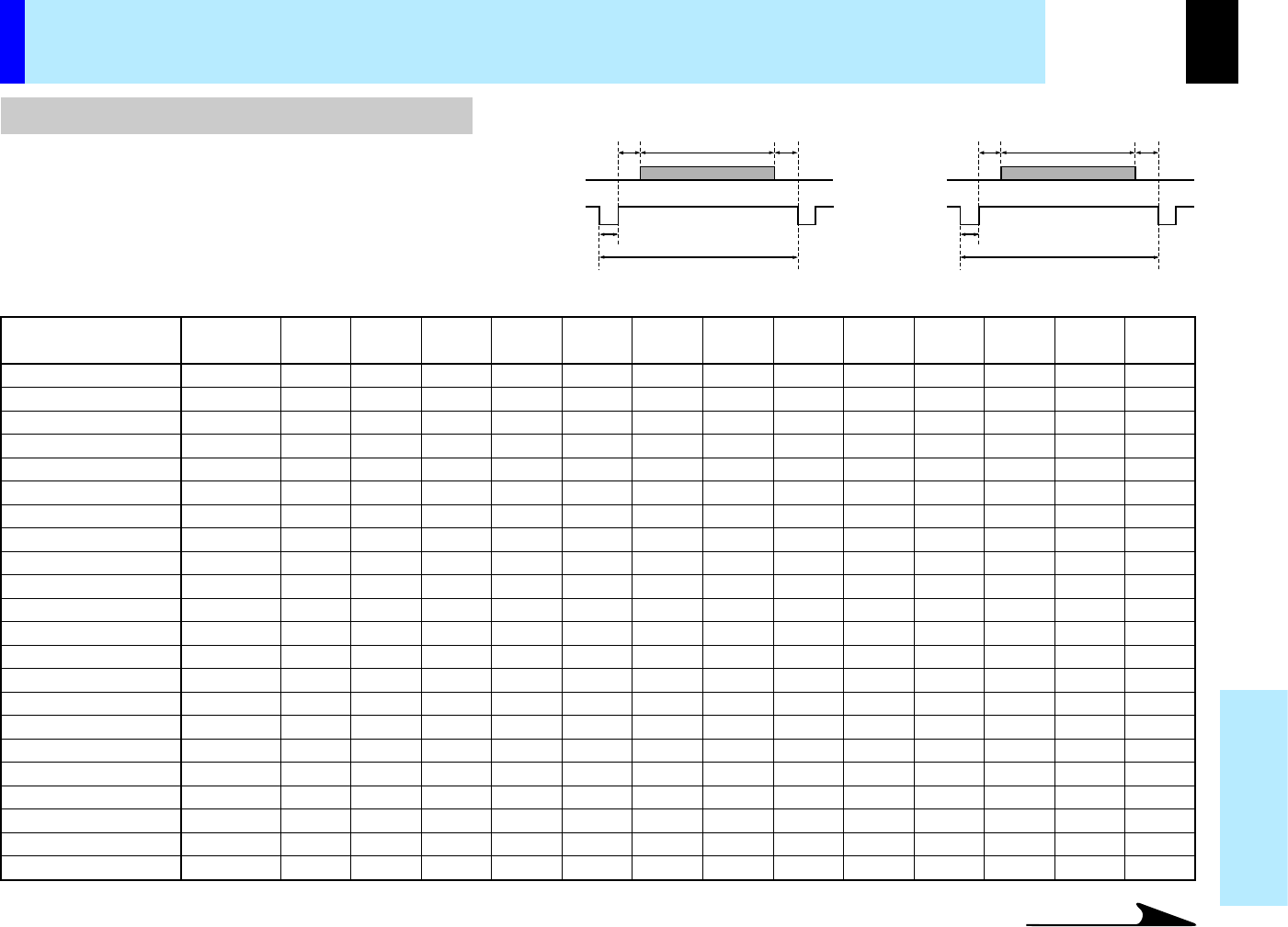
Determine the screen size projected on the screen.
The projection size depends on the distance between the lens and the screen.
Adjust the projection size by changing the distances as shown below.
Screen
a: Distance between the lens and the
screen (m)
The values are approximations.
Projection size
(inches)
Minimum
(At maximum zoom)
a (min.)=
Projection size - 1.6017
27.041
a (max.) =
Projection size - 1.2699
21.463
Maximum
(At minimum zoom)
CONTENTS
19
Installation and
connection
ON / STANDBY
F
A
N
T
E
M
P
L
A
M
P
O
N
3
4
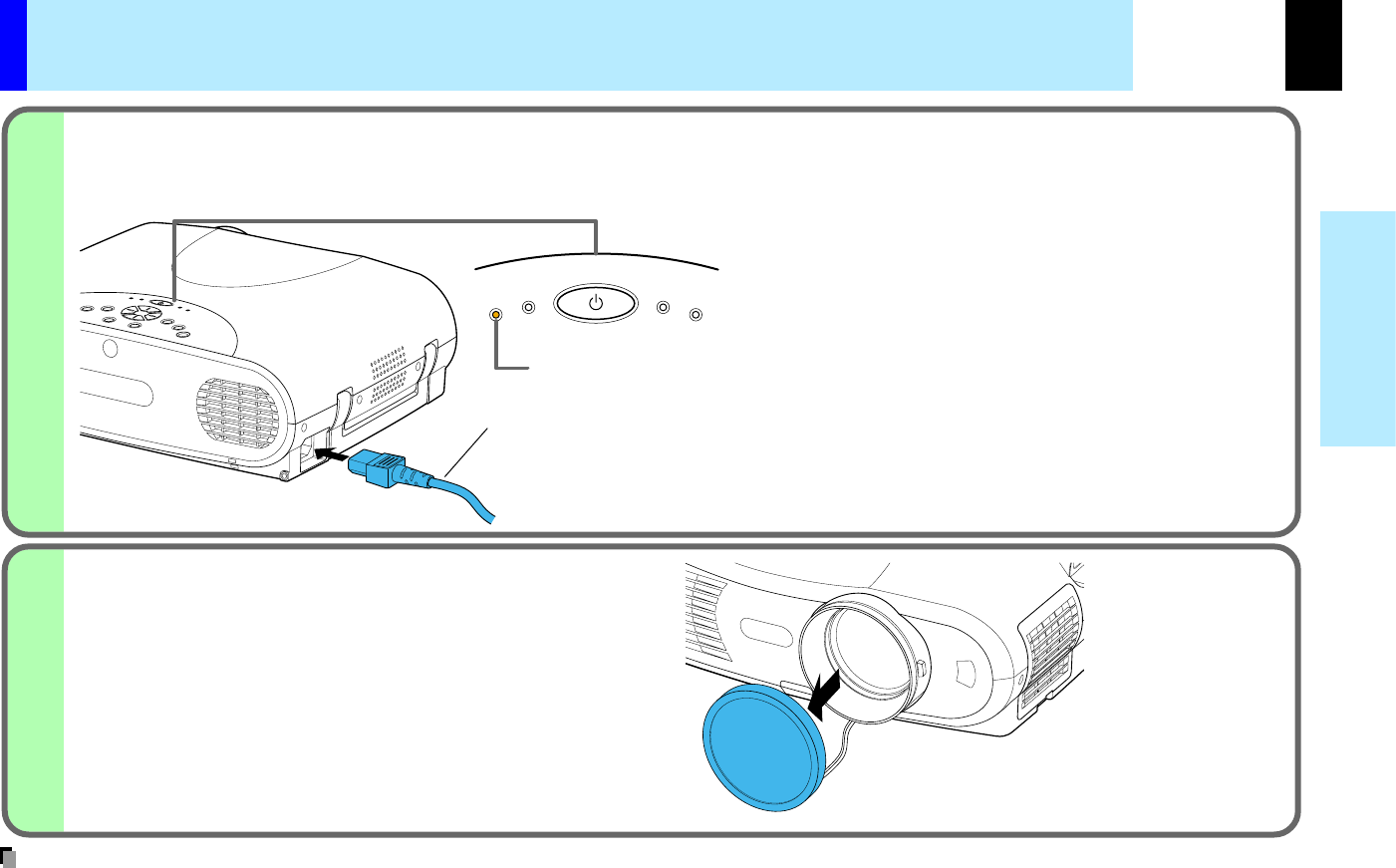
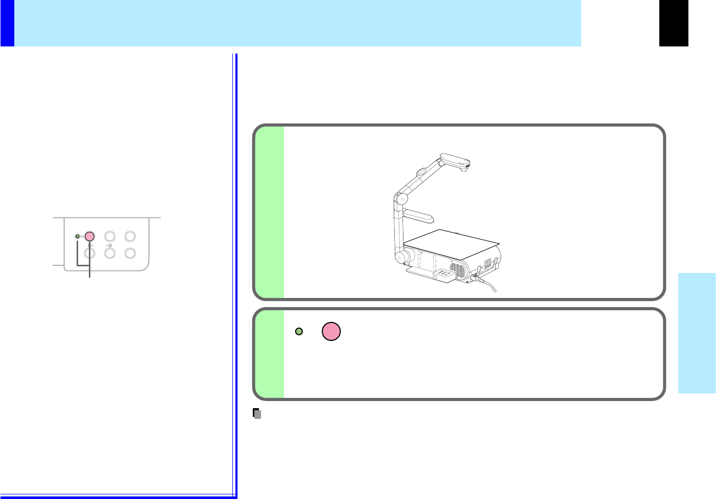
Connect the power cord.
•Insert one end in the AC IN socket on the projector.
•Insert the other end in a wall outlet.
Power cord (Supplied)
Light (Orange)
The three indicators, TEMP, LAMP, and ON, light in green
for several seconds and then the ON indicator lights in
orange and the projector turns to the standby mode.
Do not perform any operations while the three indicators
are lit green.
Take off the lens cover.
•When the projector is moved from a cold location to a warm location, or when the ambient temperature in the projection room has risen suddenly,
moisture may condense on the lens or the internal optical section to blur the projected pictures. In such a case, leave the projector for an adequate
time (1 to 2 hours, depending on the room’s condition) before using it, so it adjusts to the ambient temperature.
•If the screen is exposed to direct sunlight or other strong light, the projected picture becomes too faint to see. Shut out the light with curtains or other
means.
•If the screen and the projector are not installed properly, the projected picture may be distorted.
Floor-mounted projector placement (continued)
Notes
CONTENTS
20
Installation and
connection
2
1
Projector placement angle adjustment
The tilt of the projector can be adjusted using the foot adjuster.
Lift the front of the projector until a tilt angle desired
is obtained and hold down the foot adjuster release
button.
The foot adjuster will stretch.
Release the button to lock in position.
Turn the foot adjuster to make fine adjustment of the
height.
Turn clockwise to lift up.
Turn counterclockwise to lower.
Foot adjuster
release button
Foot adjuster
Lift up
Lower
•To put the foot adjuster back, hold down the foot adjuster release button and lower the front slowly.
•Be sure to hold the projector when putting the foot adjuster back so as not to let the front fall on your fingers.
•Do not tilt the projector at an angle exceeding the range adjustable by the foot adjusters, since the duration life of the lamp may be shortened.
Notes
CONTENTS
21
Installation and
connection
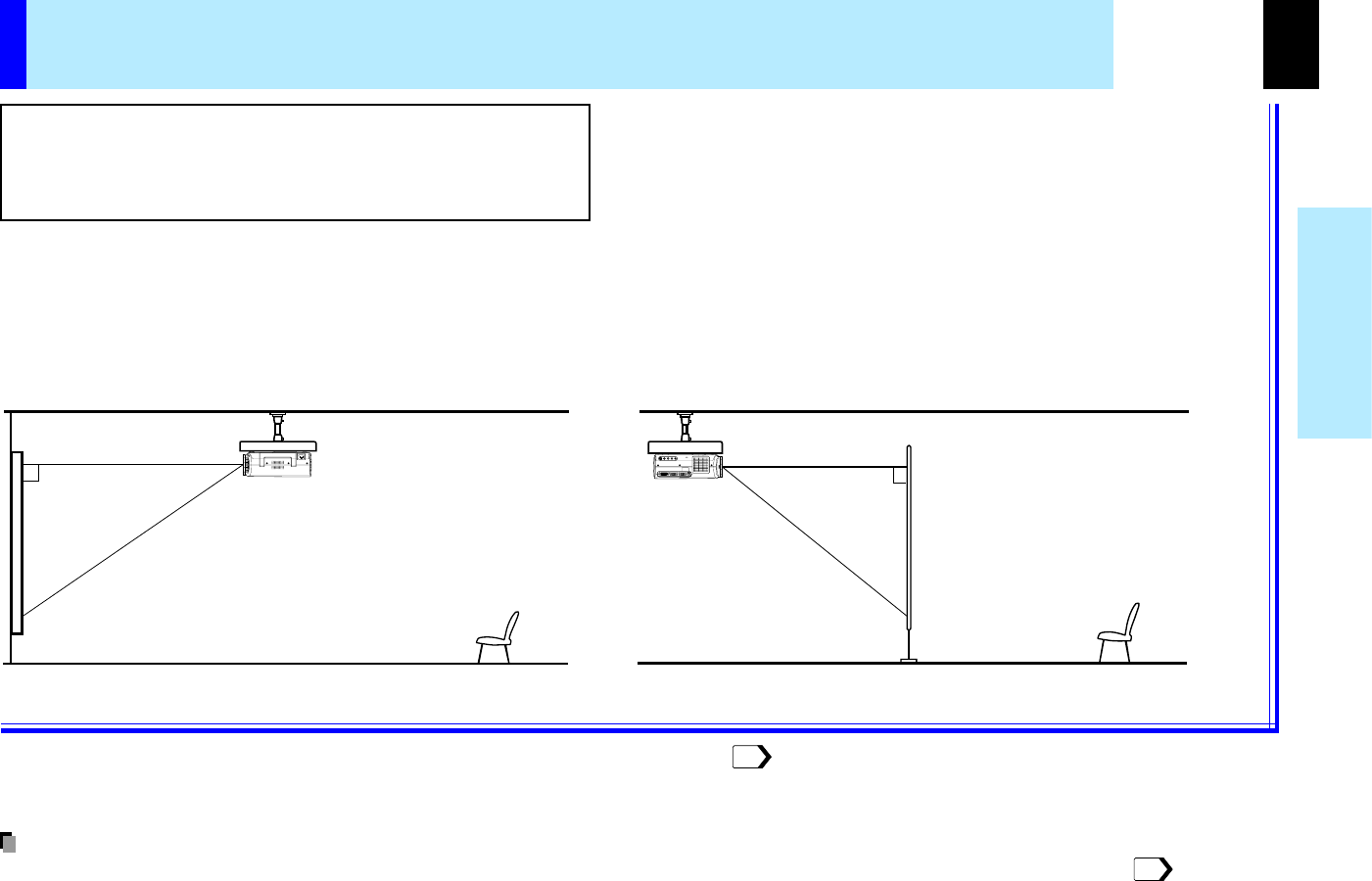
Ceiling-mounted projector placement
Perform the "Projection mode" setting on the menu screen for the projection method.
•The relation between the projection size and the distance to the screen is the same as that of the floor-mounted projection mode.
CAUTION
When a ceiling mount is required, please consult with the
dealer.
Ceiling-mounted front projection
Viewing a picture projected on the front of the screen from a ceiling
installation.
Ceiling-mounted rear projection
Viewing a picture projected through the back of the screen from a
ceiling installation.
Translucent screen
51
18
Note
CONTENTS
22
Installation and
connection
USB
COMPUTER IN 1
COMPUTER IN 2
S-VIDEOVIDEO
VIDEO IN
R - AUDIO - L
AUDIO
IN
(
Y/P
B
/P
R
)
MONITOR
OUT
CONTROL
Continued
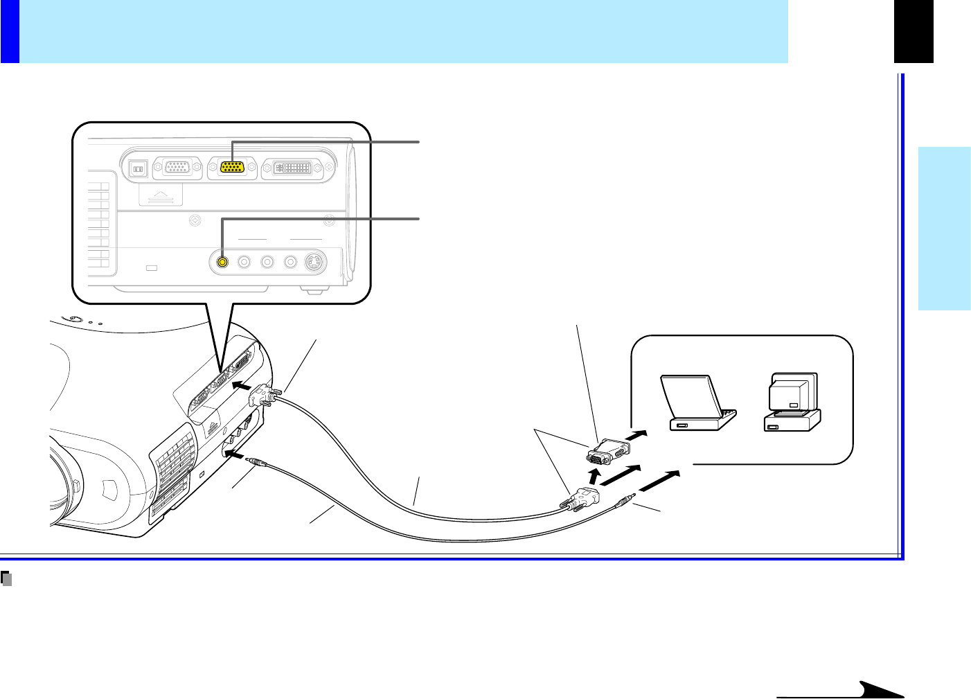
Connecting a computer (COMPUTER IN 1 connector)
•The projector cannot be connected to a computer without an analog RGB connector. For details, refer to the computer manual.
•You may not be able to connect some computers to the projector. For details, consult the dealer.
•When connecting to a Macintosh computer, use the supplied Mac adapter (Multiple Scan 21 compatible). For some models the adapter is not
required.
•Some computers may have output modes which are not compatible with this projector. Check the compatibility of the connectors, signal levels, timing,
resolutions, etc.
You can project the picture from the computer.
Check that the power for the projector and computer is off before connecting the cables.
COMPUTER IN 1 Connector
For use as both Analog RGB (1) and Y/PB/PR input. At shipping from
factory, it is set for use as Analog RGB (1) input.
AUDIO IN jack
For use as both audio signals for RGB input (analog RGB (1)/analog RGB (2)/
digital RGB) and Y/PB/PR input.
Computer
To monitor port
RGB cable
(Supplied)
To AUDIO IN jack
Audio cable (Supplied)
φ
3.5mm Stereo mini-jack
To audio output port
To COMPUTER IN 1 Connector
Be sure to connect in the proper
direction.
Connecting a Mac adapter for
Macintosh computers (Supplied)
Notes
CONTENTS
23
Installation and
connection
Continued
USB
COMPUTER IN 1
COMPUTER IN 2
S-VIDEOVIDEO
VIDEO IN
R - AUDIO - L
AUDIO
IN
(
Y/P
B
/P
R
)
MONITOR
OUT
CONTROL
You can project the picture of analog RGB or digital RGB signal from a computer by using COMPUTER IN 2 connector.
Check that the power for the projector and computer is off before connecting the cables.
COMPUTER IN 2 Connector (DVI connector)
For use as both Analog RGB (2) input and Digital RGB input. At shipping
from factory, it is set for use as Analog RGB (2) input. Change the setting on
the menu screen when using as Digital RGB input.
AUDIO IN jack
For use as both audio signals for RGB input (analog RGB (1)/analog RGB
(2)/digital RGB) and Y/PB/PR input.
(Please also read "Notes" on page 22.)
•DVI digital cable should be purchased separately when you input a digital RGB signal.
•Although infrequent, noise might be generated on the screen depending on the type of computer and the connection cables. Should this occur, reduce
the refresh rate of the computer signal, or lower the resolution. Use of connection cables that are 2 m or shorter is recommended.
•The input signal specifications of the DVI port of the projector conform to DVI 1.0 specifications; however, contents protection is not supported. Note
that there is no guaranty of the operations not specified in this specifications.
Connecting a computer (COMPUTER IN 2 connector)
Computer
To monitor port
DVI analog cable
(Supplied)
To AUDIO IN jack
Audio cable (Supplied)
φ
3.5mm Stereo mini-jack
To audio output port
To COMPUTER IN 2 Connector
Be sure to connect in the proper
direction.
Connecting a Mac adapter for
Macintosh computers (Supplied)
45
Notes
CONTENTS
24
Installation and
connection
USB
COMPUTER IN 1
COMPUTER IN 2
S-VIDEOVIDEO
VIDEO IN
R - AUDIO - L
AUDIO
IN
(
Y/P
B
/P
R
)
MONITOR
OUT
CONTROL
Continued
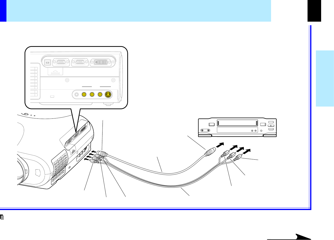
You can project the picture from video equipment by using VIDEO IN connectors.
Check that the power for the projector and video equipment is off before connecting the cables.
To S-VIDEO connector
Be sure to connect in the
proper direction.
To S-video output
S-video cable
(Not supplied)
(Red) To AUDIO-R jack
(White) To AUDIO-L jack
(Yellow) To VIDEO jack
AV cable
(Supplied)
Pin plug (red)
To audio output (R)
Pin plug (white)
To audio output (L)
Pin plug (yellow)
To video output
•The S-VIDEO connector and VIDEO jack can be used independently, but the audio input jacks are used as both the S-VIDEO and VIDEO input.
Video equipment
Connecting video equipment
Note
CONTENTS
25
Installation and
connection
USB
COMPUTER IN 1
COMPUTER IN 2
S-VIDEOVIDEO
VIDEO IN
R - AUDIO - L
AUDIO
IN
(
Y/P
B
/P
R
)
MONITOR
OUT
CONTROL
Continued
You can project the picture from video equipment with component video output jack.
Check that the power for the projector and video equipment is off before connecting the cables.
COMPUTER IN 1 Connector
For use as both Analog RGB (1) and Y/PB/PR input. At shipping from
factory, it is set for use as Analog RGB (1) input.
Change the setting on the menu screen when using as Y/PB/PR input.
AUDIO IN jack
For use as both audio signals for RGB input (analog RGB (1)/analog RGB
(2)/digital RGB) and Y/PB/PR input.
Adapter
BNC-pin
(Not supplied)
Monitor cable
Mini D-sub 15P-BNC
(Not supplied)
To AUDIO IN jack
Audio cable (Not supplied)
To COMPUTER IN 1 Connector
Be sure to connect in the proper
direction.
Pin plug (red)
To audio output (R)
Pin plug (white)
To audio output (L)
(Green) To Y video output
(Blue) To PB video output
(Red) To PR video output
Video equipment
(DVD player, etc.)
Connecting video equipment (continued)
45
CONTENTS
26
Installation and
connection
USB
COMPUTER IN 1
COMPUTER IN 2
S-VIDEOVIDEO
VIDEO IN
R - AUDIO - L
AUDIO
IN
(
Y/P
B
/P
R
)
MONITOR
OUT
CONTROL
73
Note
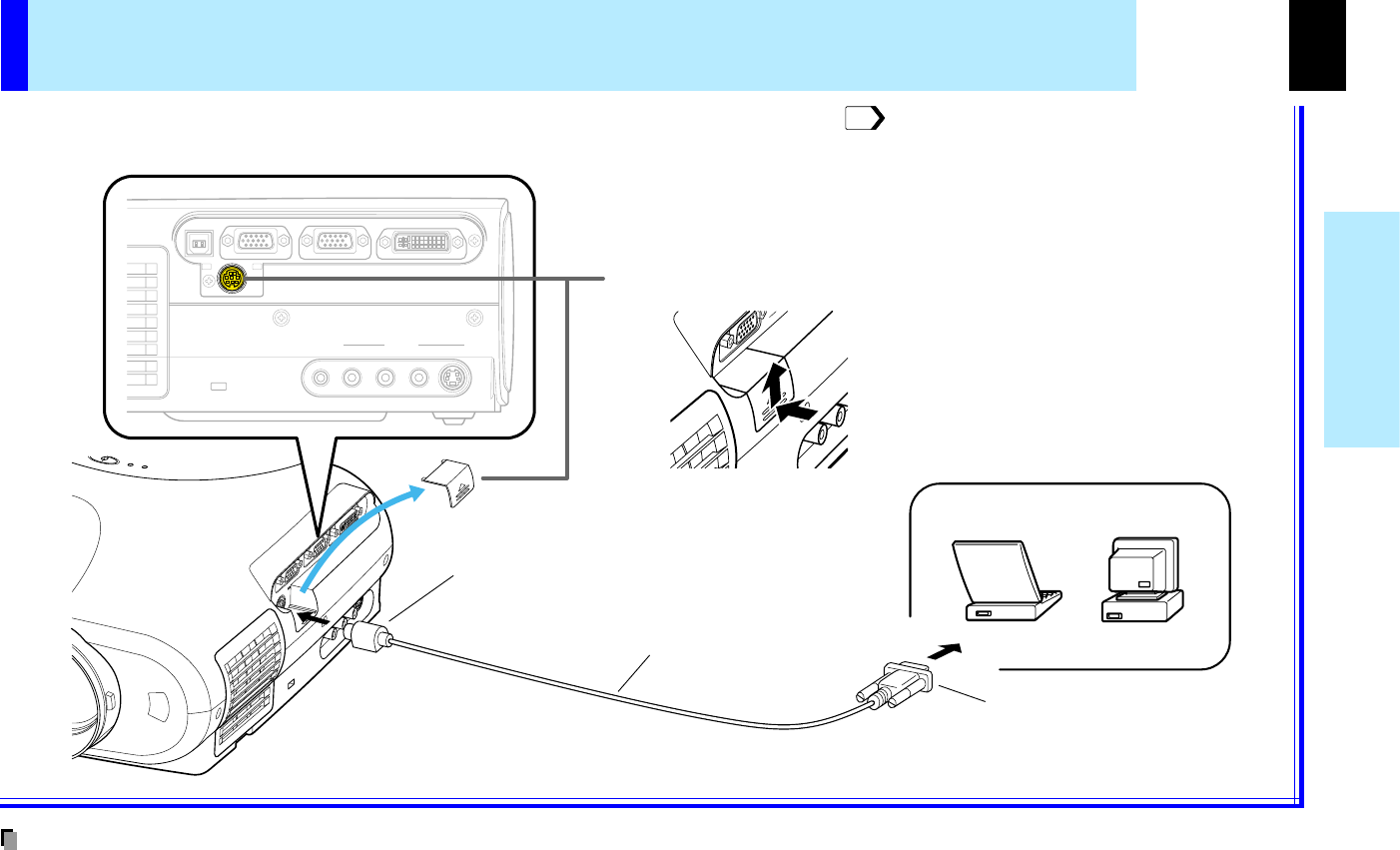
Remove the cover when using the CONTROL connector.
Projector operation control by a computer
You can control the projector by a computer connected with the control cable supplied.
Check that the power for the projector and computer is off before connecting the cables.
To CONTROL connector
Be sure to connect in the
proper direction.
Control cable
(Supplied)
Computer
To RS-232C port
•Do not connect a cable other than the exclusive one supplied.
To remove the cover, slide it up while pushing it.
CONTENTS
27
Installation and
connection
USB
COMPUTER IN 1
COMPUTER IN 2
S-VIDEOVIDEO
VIDEO IN
R - AUDIO - L
AUDIO
IN
(
Y/P
B
/P
R
)
MONITOR
OUT
CONTROL
Continued
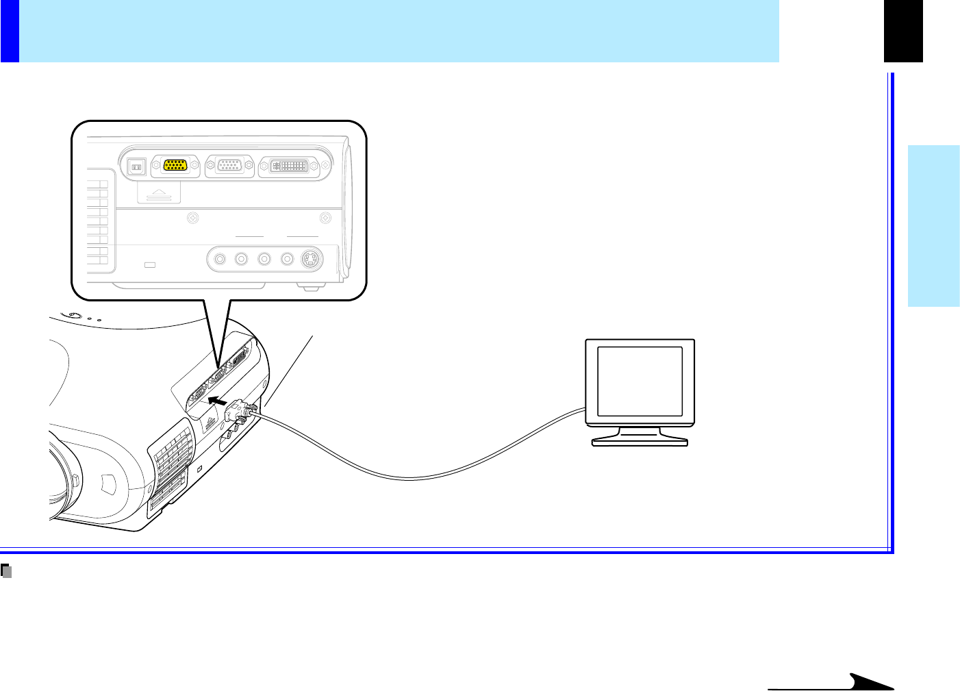
Computer monitor, etc.
•The analog RGB signals or Y/PB/PR signals of the COMPUTER IN 1 or COMPUTER IN 2 connector selected by the input select operation are output
from the MONITOR OUT connector. If neither of these input sources is selected, the signal of the COMPUTER IN 1 connector is output. (Digital RGB
signals are not output.)
•Signals are output from the MONITOR OUT connector even when in the standby mode.
•A general computer monitor may not display a normal picture with Y/PB/PR signals.
You can output video signal to a computer monitor, etc.
Check that the power for the projector and the equipments is off before connecting the cables.
How to use the output connector
To MONITOR OUT connector
Be sure to connect in the
proper direction.
Notes
CONTENTS
28
Operations
K
E
Y
S
T
O
N
E
A
U
T
O
S
E
T
E
X
I
T
ON / STANDBY
VOL / ADJ
E
N
T
E
R
M
E
N
U
I
N
P
U
T
F
A
N
T
E
M
P
L
A
M
P
O
N
1
1
1
1
2
ON/STANDBY
ON/STANDBY
1
MENU
ON/STANDBYINPUT
L-CLICKR-CLICK
ENTER
KEYSTONE
AUTO
SET
EXIT
PIP
FREEZE
MUTECALL
RESIZE
VOLUME/ADJUST
LASER
ON / STANDBY
F
A
N
T
E
M
P
L
A
M
P
O
N
ON / STANDBY
F
A
N
T
E
M
P
L
A
M
P
O
N
Continued
•The startup screen disappears when you push the EXIT button or waited for a while. You
can also set the startup screen not to be displayed on the menu screen.
•When a projector is used for the first time, language selection menu is displayed after the
startup screen disappears. Set it up with procedures 2 and 3 of the next page.
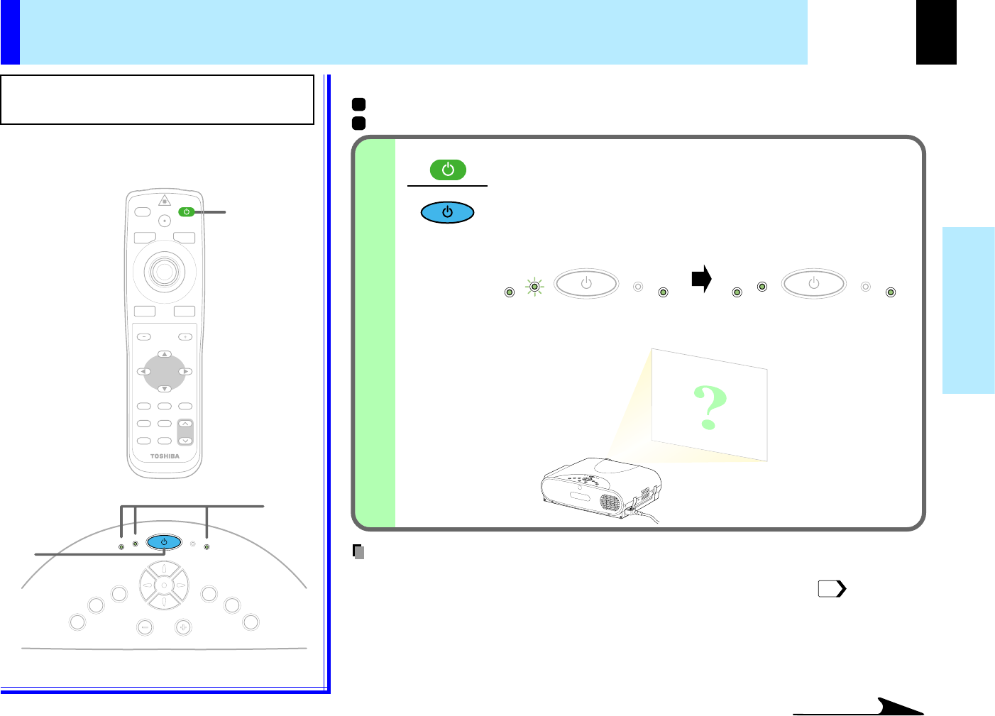
Projection on the screen
CAUTION - Do not look into the projection lens
while operating the projector.
Preparation
Install and connect the projector properly.
Take off the lens cover.
Press ON/STANDBY.
The projector turns on and the ON, LAMP and FAN
indicators light in green.
(The LAMP indicator blinks while the lamp is warming up.)
(Green)
The lamp lights and the startup screen appears.
Remote control
Control panel
(Main unit side)
Indicators
(Green)
(Green)(Green)
(Green)
(Green)
Flashing
Notes
51
CONTENTS
29
Operations
2
ENTER
ENTER
3
ENTER
ENTER
4
MENU
ON/STANDBYINPUT
L-CLICKR-CLICK
ENTER
KEYSTONE
AUTO
SET
EXIT
PIP
FREEZE
MUTECALL
RESIZE
VOLUME/ADJUST
LASER
22,3
2
2,3
K
E
Y
S
T
O
N
E
A
U
T
O
S
E
T
E
X
I
T
ON / STANDBY
VOL / ADJ
E
N
T
E
R
M
E
N
U
I
N
P
U
T
F
A
N
T
E
M
P
L
A
M
P
O
N
Continued
Projection on the screen (continued)
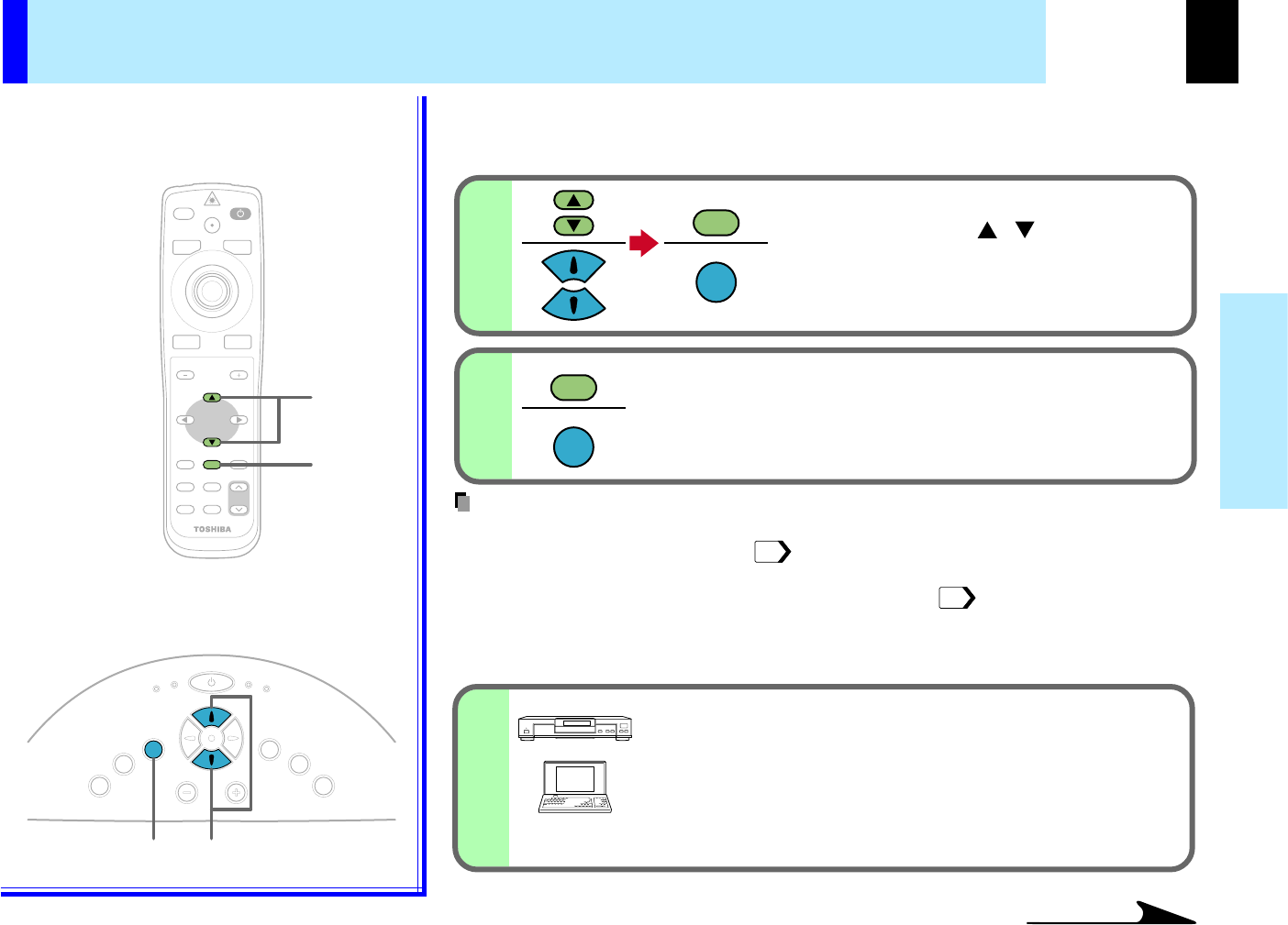
When a projector is used for the first time, the language selection menu, which is to
select a language for displaying menus or messages, is displayed. Select a desired
language. (At shipping from factory, it is set to English.)
Select a desired language with the
selection button ( ), and press
ENTER.
A menu confirming the selection result is
displayed with the selected language.
/
Press ENTER to decide.
Press EXIT to return to step 2 when you want to re-select a
language.
•The language selection menu will not be displayed on and after the second time you turn on
the power. However, if "Reset all" is executed, the language selection menu will be
displayed when the power is turned on next time.
•The language can also be selected on the menu screen.
Turn on the connected equipment and put it
in playback mode.
Select "Cancel" or install "plug and play monitor" of
Windows
(R)
when the dialog box of Add New Hardware
Wizard screen appears on the computer when connecting
a computer.
Remote control
Control panel
(Main unit side)
52
50
Notes
CONTENTS
30
Operations
MENU
ON/STANDBYINPUT
L-CLICKR-CLICK
ENTER
KEYSTONE
AUTO
SET
EXIT
PIP
FREEZE
MUTECALL
RESIZE
VOLUME/ADJUST
LASER
5-a
INPUT
INPUT
5-b
INPUT
INPUT
5-a,5-b
5-b
5-a,5-b5-b
K
E
Y
S
T
O
N
E
A
U
T
O
S
E
T
E
X
I
T
ON / STANDBY
VOL / ADJ
E
N
T
E
R
M
E
N
U
I
N
P
U
T
F
A
N
T
E
M
P
L
A
M
P
O
N
ENTER
ENTER
Continued
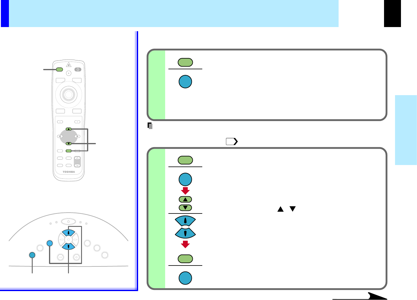
Select the input source to project.
There are two kinds of methods as follows (5-a and 5-b.)
Select the input source by pressing INPUT
repeatedly.
At shipping from factory, "Analog RGB(1)" connected to
COMPUTER IN 1 connector or "Video" connected to VIDEO
Jack can be selected. (You can select "Camera" when
using the model with a document imaging camera.)
The icon and the name of the selected input source appear
on the screen.
•The types of input sources selected when the INPUT button is pressed repeatedly can be
set from the menu screen.
Press INPUT and hold for two seconds.
The input source selection menu appears.
Select the input source to project with the
selection button ( ).
Regardless of the contents of input source settings on the
menu screen, all the input sources are displayed here to be
selected.
Press ENTER
A picture of the selected input source is projected.
When a sound signal source is also connected, sound is
developed from the speaker.
Remote control
Control panel
(Main unit side)
Projection on the screen (continued)
45
/
Note
CONTENTS
31
Operations
4
5
45
Continued
Projection on the screen (continued)
(Signal sent from the computer)
•If you project an image from a computer with an LCD screen while monitoring the image on
the computer, the image may not be projected properly, depending on the computer model.
In this case, turn off the computer display. For details on controlling the computer display,
etc., refer to the computer's manual and description on the software for the computer used.
•The projector projects an image by XGA signal (1024 x 768) in full screen.
•The image quality of a computer signal except XGA may deteriorate. It is recommended to
set the external monitor connected to the computer to XGA mode (1024 x 768).
•The projector can be also applied to DDC2B (Display Data Channel 2B). If your computer is
applied to the DDC, start up your computer after turning on the projector.
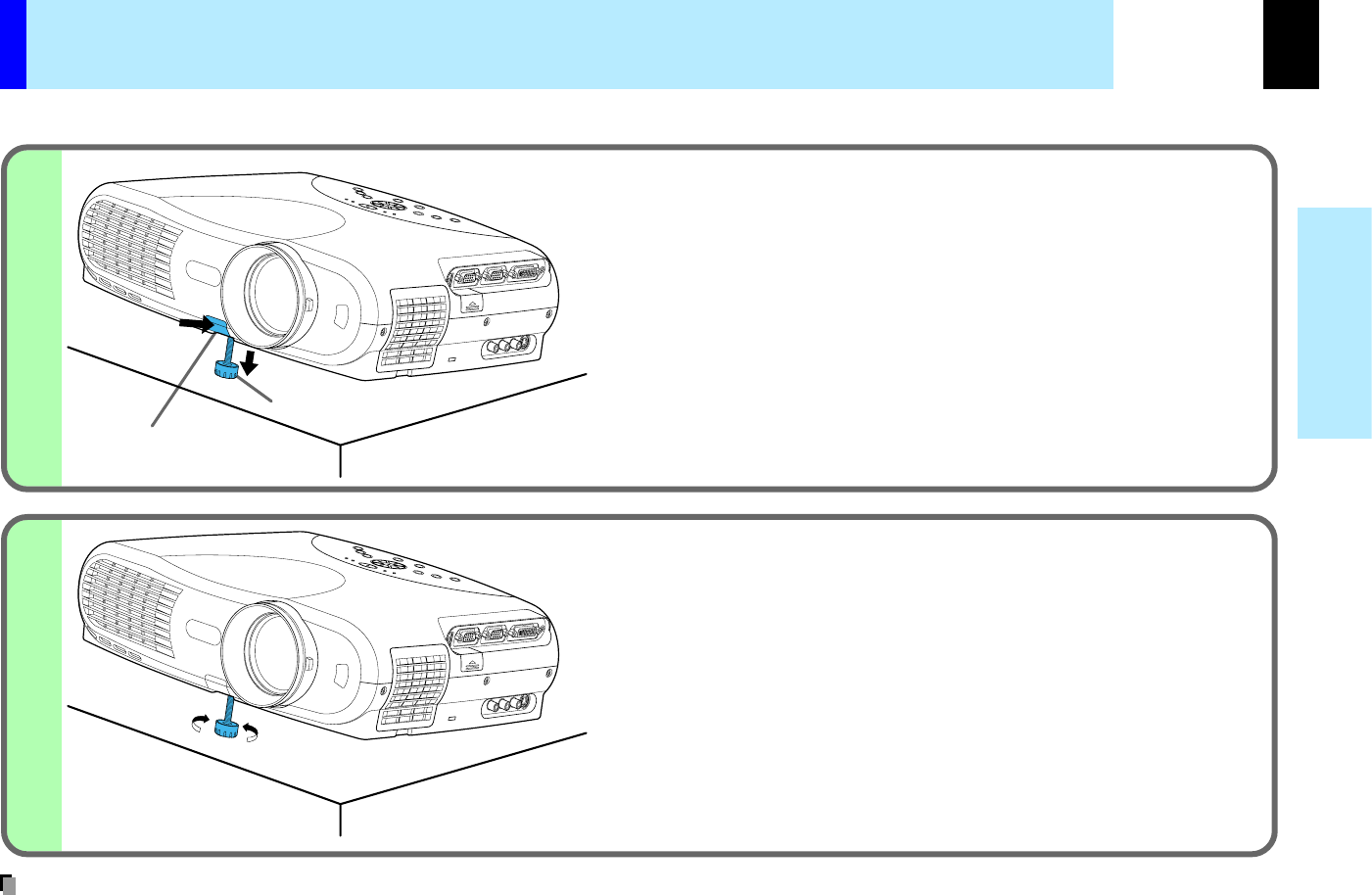
Adjust the picture size by turning the
zooming lever.
Turn to the right to enlarge the picture.
Turn to the left to reduce the picture.
Focus on the picture by turning the
focusing ring.
A still picture is recommended for focusing.
Notes
CONTENTS
32
Operations
K
E
Y
S
T
O
N
E
A
U
T
O
S
E
T
E
X
I
T
ON / STANDBY
VOL / ADJ
E
N
T
E
R
M
E
N
U
I
N
P
U
T
F
A
N
T
E
M
P
L
A
M
P
O
N
6
6
6
MENU
ON/STANDBYINPUT
L-CLICKR-CLICK
ENTER
KEYSTONE
AUTO
SET
EXIT
PIP
FREEZE
MUTECALL
RESIZE
VOLUME/ADJUST
LASER
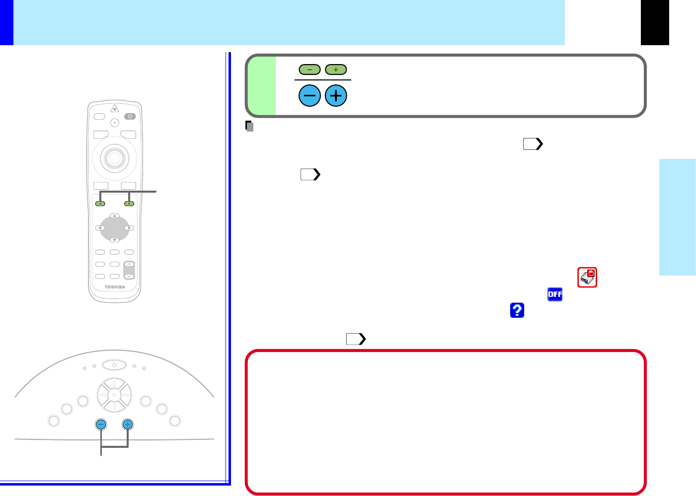
Press VOL/ADJ (+/-) to adjust volume.
Press the (+) button to increase volume.
Press the (-) button to decrease volume.
Remote control
Control panel
(Main unit side)
Projection on the screen (continued)
•When changing the projecting angle, adjust the foot adjuster.
•When the screen image is distorted in keystone, press the KEYSTONE button to adjust the
distortion.
•Due to the lamp characteristic, flickers may occasionally occur in a picture. This is not
malfunction of the unit.
•The lamp may rarely burst with a big sound.
•The projector's liquid crystal panel is made using extremely advanced technology, but there
may be black spots (pixels that do not light) or bright spots (pixels that are constantly lit) on
the panel. Please note that these are not malfunctions.
•When trying to press the button whose operation is not available, the icon appears.
•When supplying the signal not compatible to the projector, the icon appears.
•When signals are not input from the input source, the icon appears.
•The projector may stop operating if the surrounding temperature is too high or if the air filter
is clogged with dust.
20
35
62
Notes
CONTENTS
33
Operations
K
E
Y
S
T
O
N
E
A
U
T
O
S
E
T
E
X
I
T
ON / STANDBY
VOL / ADJ
E
N
T
E
R
M
E
N
U
I
N
P
U
T
F
A
N
T
E
M
P
L
A
M
P
O
N
2
1
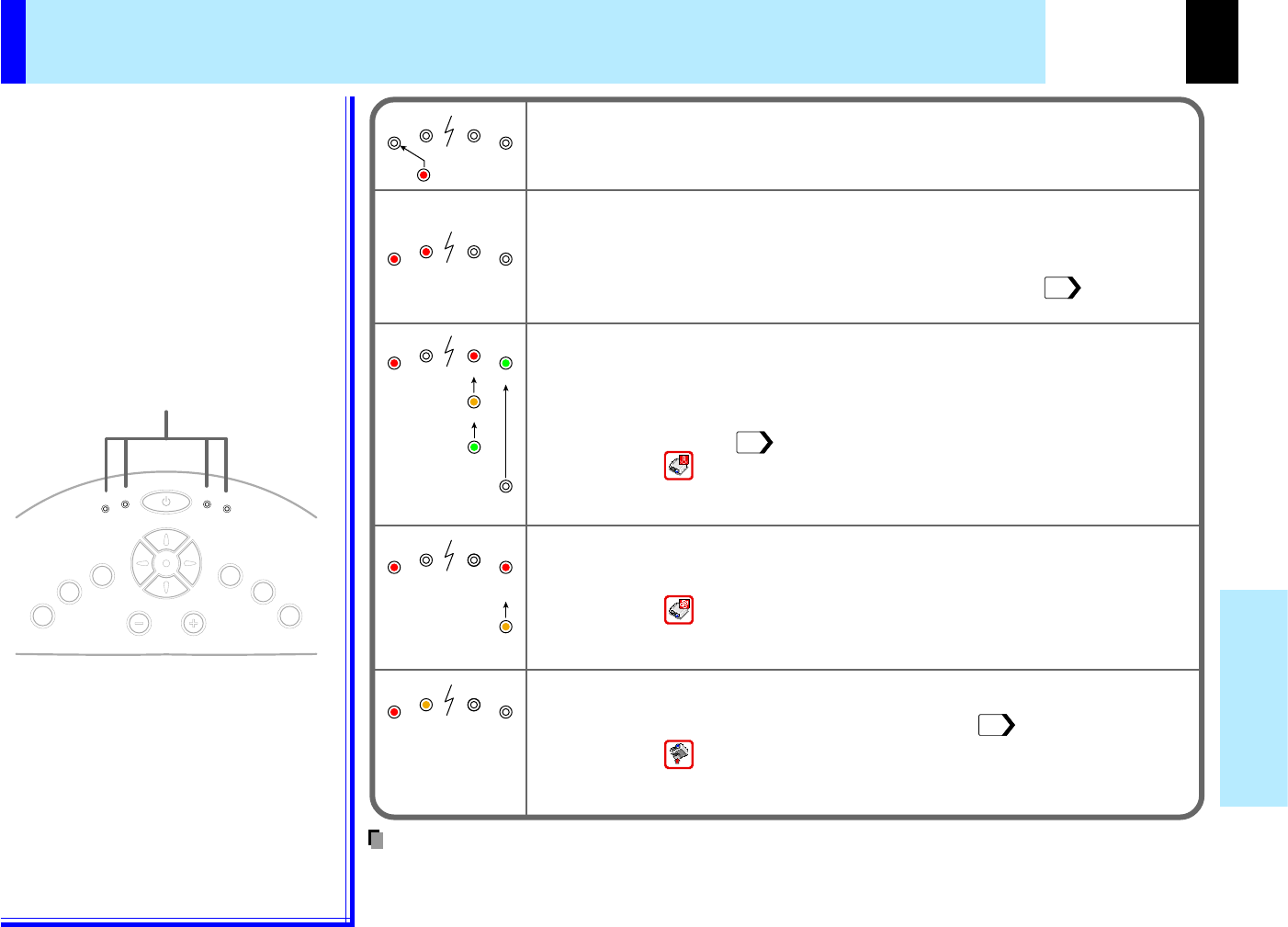
(Green)
(Green)(Green)
(Off)
(Off)(Off)
flushing
(Orange)(Orange)
A
A
B
C
BC
ON/STANDBY
ON/STANDBY
ON/STANDBY
ON/STANDBY
2
1,2
1,2
MENU
ON/STANDBYINPUT
L-CLICKR-CLICK
ENTER
KEYSTONE
AUTO
SET
EXIT
PIP
FREEZE
MUTECALL
RESIZE
VOLUME/ADJUST
LASER
ON
LAMP
FAN
ON
LAMP
FAN
ON
LAMP
FAN
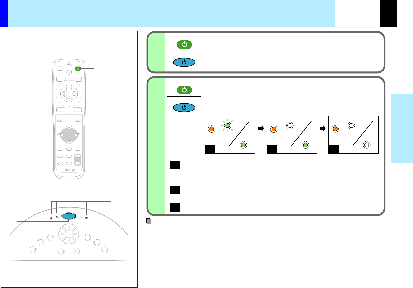
Turning the power off
Press ON/STANDBY after using the projector.
An instruction message for turning the power off appears on
the screen and disappears after a while. When the
message disappears, operation becomes invalid.
Press ON/STANDBY again.
Cooling starts. Once cooling is completed, the LAMP and
FAN indicators turn off and the standby mode is set. (The ON
indicator turns in orange.)
To protect the light source lamp, the LAMP indicator blinks as long as a mini-
mum of cooling is necessary. The power cannot be turned back on during this
time. Unplugging the power cord at this time will shorten the lamp's duration life.
The cooling fan continues to run for a while to expel the heat remaining inside.
If you are in a hurry, however, you may unplug the power cord at this time.
The standby mode is set.
•The projector consumes about 20W of power in the standby mode. We recommend you to
unplug the power cord when not using the projector for long periods of time.
•Be sure that the LAMP indicator has turned off before unplugging the power cord. Cutting
the power by unplugging the power cord while the projector is operating or the light
source lamp is being cooled will shorten the lamp's duration life. Should a fault or some
other irregularity arise with this unit, unplug the power cord.
•When reinserting the power plug before the lamp has cooled, please wait until the lamp has
cooled sufficiently before use. When the lamp is at a high temperature, it may not light and
the duration life will be shortened.
Remote control
Control panel
(Main unit side)
Indicators
Notes
CONTENTS
34
Operations
K
E
Y
S
T
O
N
E
A
U
T
O
S
E
T
E
X
I
T
ON / STANDBY
VOL / ADJ
E
N
T
E
R
M
E
N
U
I
N
P
U
T
F
A
N
T
E
M
P
L
A
M
P
O
N
AUTO SET
AUTO SET
AUTO SET
SET
2
1
MENU
ON/STANDBYINPUT
L-CLICKR-CLICK
ENTER
KEYSTONE
AUTO
SET
EXIT
PIP
FREEZE
MUTECALL
RESIZE
VOLUME/ADJUST
LASER
Adjusting the picture automatically
You can adjust the optimum horizontal position, vertical position, sampling phase
and sampling frequency for projecting analog RGB signals at the touch of a button.
Input full screen video signals from the input
source (computer) and project the image.
Adjustments may not be performed properly for images that
are not displayed on the entire screen or extremely dark
images.
Press AUTO SET.
The horizontal position, vertical position, sampling phase and
sampling frequency are adjusted automatically.
The icon appears during signal processing.
•Automatic adjustment may not be performed properly for signals other than the computer’s
signals with which the projector is compatible.
•The horizontal position, vertical position, sampling phase and sampling frequency can also
be adjusted from the menu screen.
* Sampling frequency
Analog RGB signals input from the computer are converted into digital signals inside the
projector. The sampling frequency is the number of times per second the analog signals
are converted into digital signals. In order to capture (sample) each individual dot of the
computer’s signals, the sampling frequency must be adjusted to match the computer's dot
clock frequency. If this adjustment is off, details of the image may be blurred, a striped
pattern may appear when images with many vertical lines are displayed, or the image's
width may change. For computer’s signals with which the projector is compatible, the
sampling frequency is adjusted automatically even without pressing the AUTO SET
button.
* Sampling phase
The sampling phase is the timing at which the computer's analog RGB signals are sampled.
If the sampling phase is off, the individual dots cannot be sampled at the proper timing,
resulting in blurred or flickering images.
Remote control
Control panel
(Main unit side)
47
Notes
CONTENTS
35
Operations
12
K
E
Y
S
T
O
N
E
A
U
T
O
S
E
T
E
X
I
T
ON / STANDBY
VOL / ADJ
E
N
T
E
R
M
E
N
U
I
N
P
U
T
F
A
N
T
E
M
P
L
A
M
P
O
N
MENU
ON/STANDBYINPUT
L-CLICKR-CLICK
ENTER
KEYSTONE
AUTO
SET
EXIT
PIP
FREEZE
MUTECALL
RESIZE
VOLUME/ADJUST
LASER
KEYSTONE
KEYSTONE
1
2
3
ENTER
ENTER
EXIT
EXIT
1
32
3
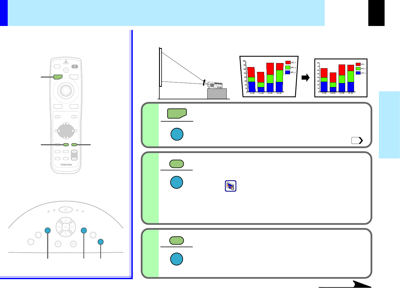
Continued
Press KEYSTONE
The keystone adjustment menu appears, with the "Auto. V-
keystone" being selected. (This menu is the same as the
sub-menu which is displayed when "Correct the keystone
distortion of the screen" is selected from GUIDE MENU. )
Press ENTER
The vertical keystone distortion on the picture projected is
automatically corrected.
The icon appears while the keystone correction is
executing.
When the correction is finished, the menu for selecting "V-
keystone" or "H-keystone" by manual adjustment appears, with
the former being selected.
Confirm the keystone distortion
When no more adjustment is needed, press the EXIT button
repeatedly until the menu disappears.
When the keystone distortion is not corrected properly, adjust
it according to the next procedure.
Remote control
Control panel
(Main unit side)
Correcting the keystone distortion
A picture may be expanded on the upper side if projected upward from the projector
lifted up by the foot adjuster. The projector can correct this keystone distortion.
Before correcting
After correcting
45
CONTENTS
36
Operations
4
6
5
EXIT
EXIT
MENU
ON/STANDBYINPUT
L-CLICKR-CLICK
ENTER
KEYSTONE
AUTO
SET
EXIT
PIP
FREEZE
MUTECALL
RESIZE
VOLUME/ADJUST
LASER
4,5
6
64,5
K
E
Y
S
T
O
N
E
A
U
T
O
S
E
T
E
X
I
T
ON / STANDBY
VOL / ADJ
E
N
T
E
R
M
E
N
U
I
N
P
U
T
F
A
N
T
E
M
P
L
A
M
P
O
N
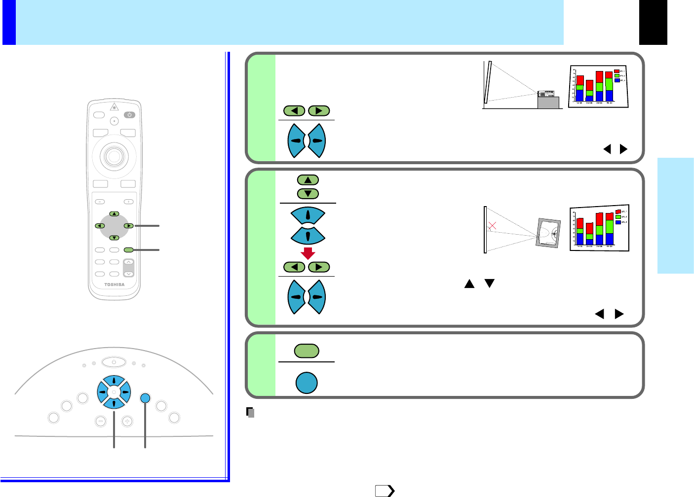
90°
The angle range of
approximately +/-10 to 90 is
adjustable.
•
Due to digital correction processing, some of the information may dropped or the picture quality may
be degraded depending on the keystone correction setting or the contents of the signal source.
•
The adjustable range of "V-keystone" or "H-keystone" is influenced by the quantity of correction
of each other.
•
When "Auto. V-keystone" does not operate properly even with the screen installed vertically,
execute "H-reference reset" .
Adjust the distortion of the both sides (right and
left) of the picture with the selection button ( ).
When screen is not installed vertically,
"Auto. V-keystone" is not corrected
properly.
/
When the projector is not installed with the angle of 90 to the screen
viewing from the top, the upper and lower sides of the projected
picture are distorted.
Select "H-keystone" from the menu with the
selection button ( ), and adjust the
distortion of the upper and lower sides of
the picture with the selection button ( ).
/
/
52
Press EXIT repeatedly until the menu disappears.
The keystone adjustment finishes.
After confirming that "V-keystone" is selected on the menu;
Correcting the keystone distortion (continued)
Remote control
Control panel
(Main unit side)
Notes
CONTENTS
37
Operations
MUTE
MENU
ON/STANDBYINPUT
L-CLICKR-CLICK
ENTER
KEYSTONE
AUTO
SET
EXIT
PIP
FREEZE
MUTECALL
RESIZE
VOLUME/ADJUST
LASER
MUTE
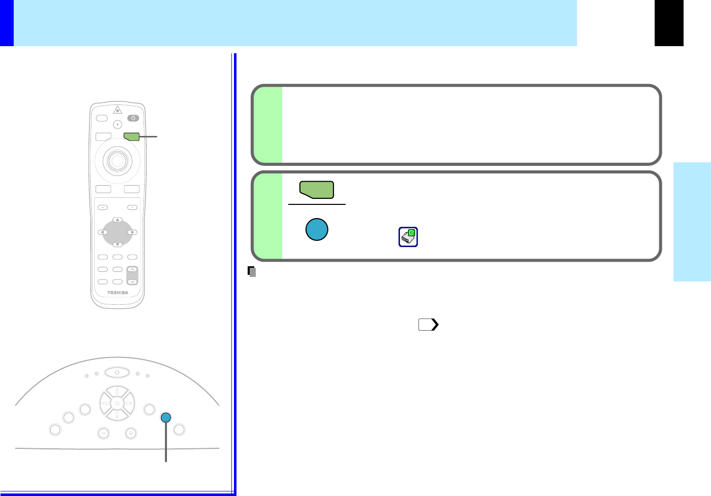
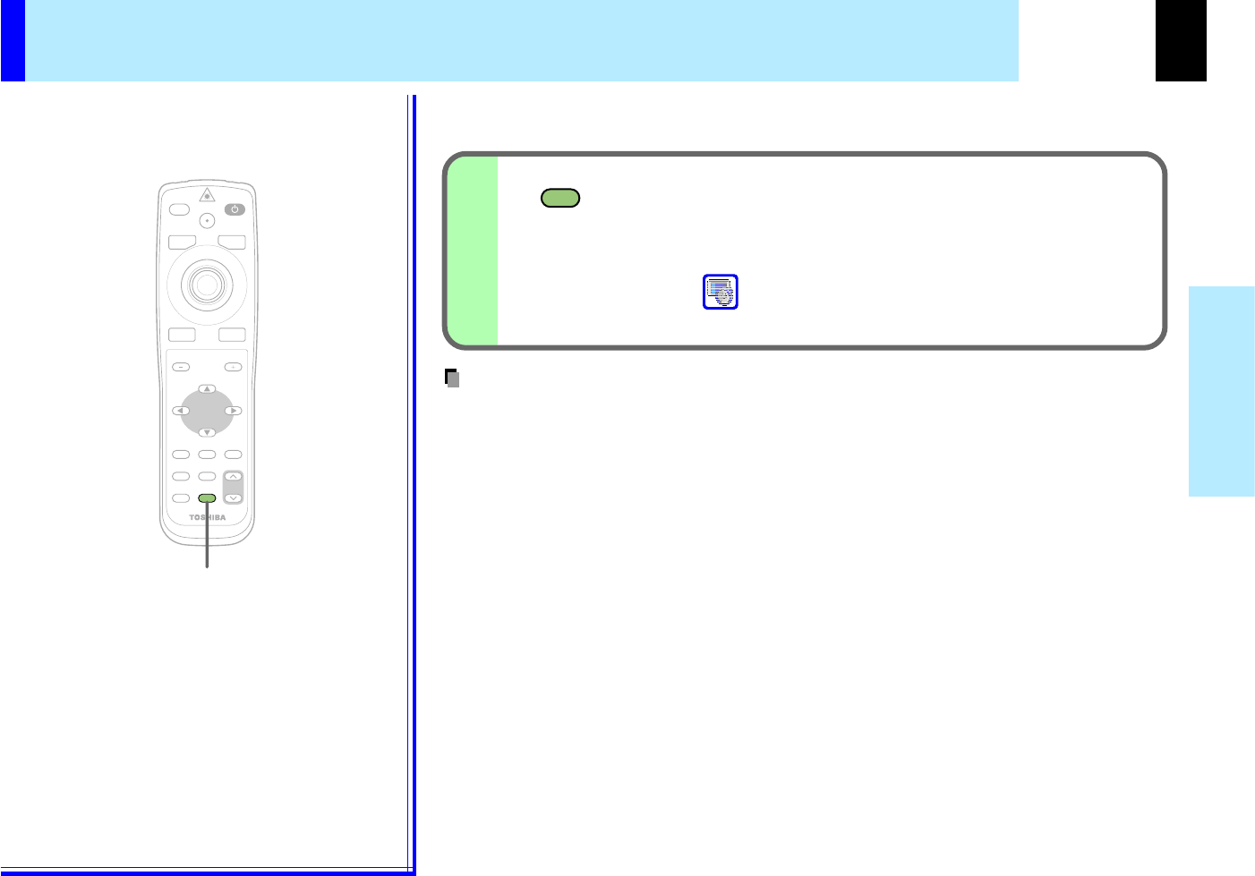
Cutting off the picture and sound temporarily
The image and sound of this projector can be turned off if you wish to temporarily
project the image of another projector or a OHP, etc., on the screen.
Press MUTE.
The sound and picture are cut off temporarily.
To cancel the mute mode, press MUTE again. The image
and sound will be output.
The icon appears in the mute mode.
•The mute mode is cancelled if another operation is performed during the mute mode.
Remote control
Note
CONTENTS
38
Operations
FREEZE
MENU
ON/STANDBYINPUT
L-CLICKR-CLICK
ENTER
KEYSTONE
AUTO
SET
EXIT
PIP
FREEZE
MUTECALL
RESIZE
VOLUME/ADJUST
LASER
FREEZE
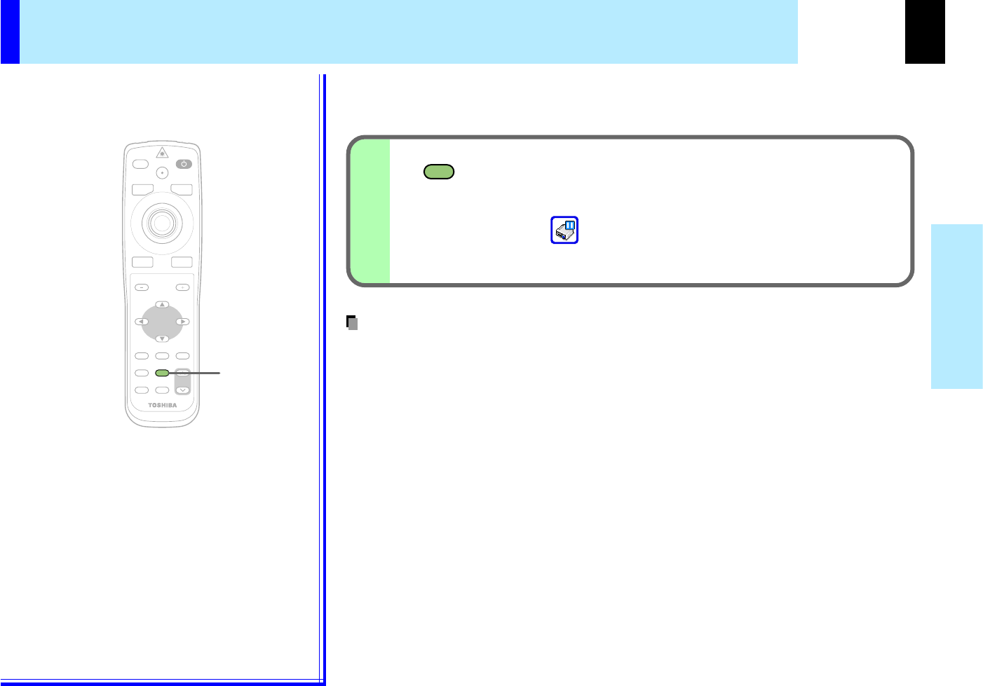
Freezing the picture
You can freeze the image being projected.
Use this function to stop images from a video recorder to make presentations.
•The frozen image can be enlarged with the RESIZE button. The freeze mode is cancelled if
any operation other than RESIZE is performed.
•The freeze mode cannot be set when there is no input (when no signals are being supplied
from a signal source).
•The input source’s image continues to play even when the projector is set to the freeze
mode.
Press FREEZE.
The picture freezes.
To release the picture, press FREEZE again.
The icon appears in the freeze mode.
Remote control
Notes
CONTENTS
39
Operations
MENU
ON/STANDBYINPUT
L-CLICKR-CLICK
ENTER
KEYSTONE
AUTO
SET
PIP
FREEZE
MUTECALL
RESIZE
VOLUME/ADJUST
LASER
EXIT
EXIT
RESIZE
RESIZE
EXIT
RESIZE
RESIZE
///
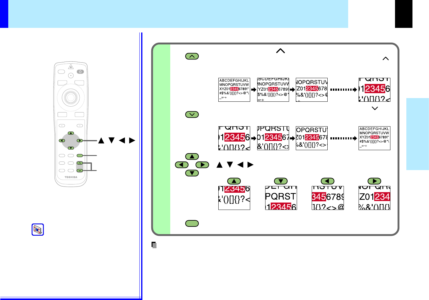
Enlarging the picture size
You can enlarge (resize) the picture size projected.
Press the EXIT button to cancel the resize mode and return to
the original size.
The icon appears in the resize mode.
Remote control
•Enlarged images can be frozen by pressing the FREEZE button. The images frozen also
can be enlarged or reduced.
•
The resize mode is cancelled if any operation other than setting the freeze mode is performed.
•This projector uses electrical digital resizing, so the picture quality degrades when images
are enlarged.
•In rare cases, the picture may be disturbed while the magnification section is being moved.
•With some signals, the image cannot be enlarged.
•This function does not work in no input status (no signal is supplied from the signal source).
The enlarged section is moved when the selection buttons
( ) are pressed. The section can be moved
continuously by keeping the button pressed in.
To reduce the enlargement ratio, press the RESIZE ( )
button. The enlargement ratio can be reduced continuously
by keeping the button pressed in.
Press RESIZE ( ).
The enlargement ratio increases each time the RESIZE ( )
button is pressed. The enlargement ratio can be increased
continuously by keeping the button pressed in.
///
Notes
CONTENTS
40
Operations
PIP
PIP
PIP
MENU
ON/STANDBYINPUT
L-CLICKR-CLICK
ENTER
KEYSTONE
AUTO
SET
EXIT
FREEZE
MUTECALL
RESIZE
VOLUME/ADJUST
LASER
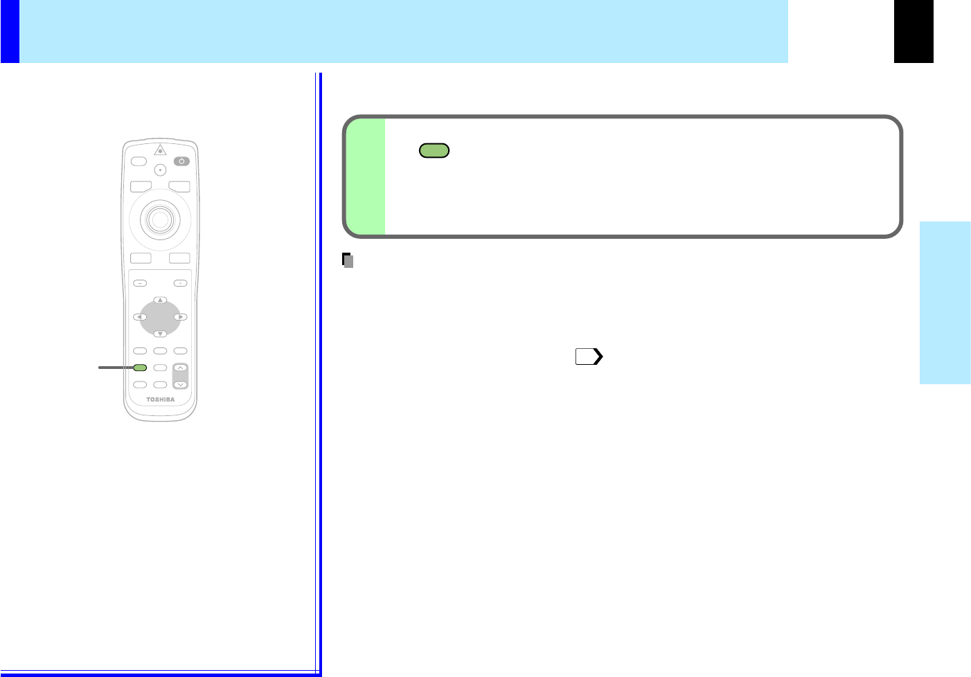
Displaying PIP Sub-pictures
Video or S-video images can be displayed as small images on the computer's
image. (Referred to as "sub-pictures" in this manual.)
Press PIP.
A sub-picture is displayed.
Press the PIP button again to turn off the sub-picture.
•The PIP function cannot be used when a source other than an RGB input source is selected.
•The PIP function cannot be used with no signals supplied from an RGB signal source.
•The sub-picture turns off if any other operation is performed.
•The signal source, size, display position and audio input source to display sub-pictures can
be changed from the menu screen.
Remote control
53
Notes
CONTENTS
41
Operations
CALL
CALL
CALL
MENU
ON/STANDBYINPUT
L-CLICKR-CLICK
ENTER
KEYSTONE
AUTO
SET
EXIT
PIP
FREEZE
MUTE
RESIZE
VOLUME/ADJUST
LASER
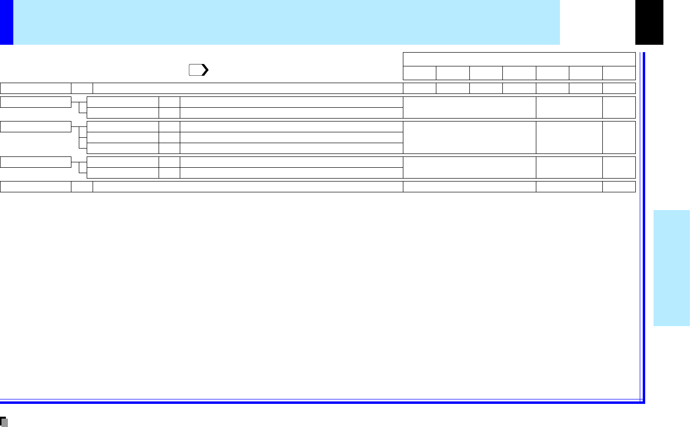
Status display
Input- current input source
H-resolution- the horizontal resolution of the input signal (at RGB input)
V-resolution- the vertical resolution of the input signal (at RGB input)
H-frequency- the horizontal frequency of the input signal (at RGB input)
V-frequency- the vertical frequency of the input signal (at RGB input)
Sync- the polarity of the sync signal (at RGB input)
Video mode- the color mode of the video signal (at Video, S-Video input)
Signal format- the formatting of the Y/PB/PR signal (at Y/PB/PR input)
Lamp time- the elapsed using time of the lamp
Version- the version of the firmware
Shutter- the shutter speed of the document imaging camera (at document
imaging camera input)
Displaying Information
Information on the input signal source, etc., can be displayed.
Press CALL.
The information described below is displayed.
The information display turns off when the CALL button is
pressed again.
•The information displayed is not refreshed even if it changes. To refresh the information,
turn off the information display, then turn it back on.
•The information display turns off if any other operation is performed.
•The "Lamp time" shows an approximate time for lamp replacement. (It should not be used
as a lamp warranty time counter.) If the time indicated here nears 1000, contact your store of
purchase about obtaining a replacement lamp (TLPL78, sold separately).
•The "Lamp time" can be reset when the lamp is replaced.
•The "Version" is the version of the control program used in the projector and is used for
servicing, etc.
Remote control
Notes
CONTENTS
42
Operations
MENU
ON/STANDBYINPUT
ENTER
KEYSTONE
AUTO
SET
EXIT
PIP
FREEZE
MUTECALL
RESIZE
VOLUME/ADJUST
LASER
MENU
ON/STANDBYINPUT
L-CLICKR-CLICK
ENTER
KEYSTONE
AUTO
SET
EXIT
PIP
FREEZE
MUTECALL
RESIZE
VOLUME/ADJUST
LASER
USB
COMPUTER IN 1
COMPUTER IN 2
S-VIDEOVIDEO
VIDEO IN
R - AUDIO - L
AUDIO
IN
(
Y/P
B
/P
R
)
MONITOR
OUT
CONTROL
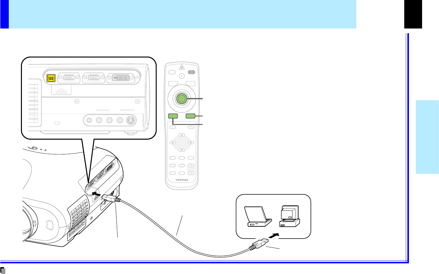
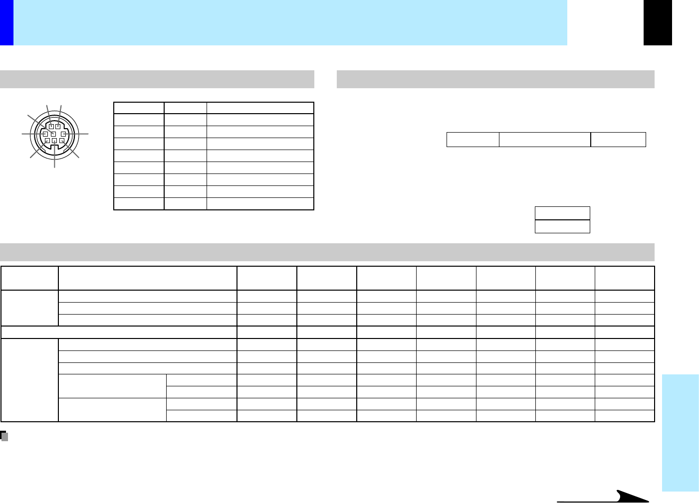
Operating a computer by the remote control
You can control a computer by the remote control when the projector and computer are connected with the supplied USB cable.
In this manual, this function is explained as "mouse remote control".
To USB connector
Be sure to connect in the
proper direction.
USB cable (supplied)
To USB port
Remote control
Pointer control
R-CLICK
L-CLICK
Point the remote control at the remote control
sensor on the projector when operating with its
buttons.
•To move the pointer Press the outer side of the
pointer control button in the direction in which
you want to move the pointer. (The speed at
which the pointer moves depends on how
strongly the button is pressed.)
•To click
Press L-CLICK or the center of the pointer
control.
•To right-click
Press R-CLICK.
•To drag and drop
While holding down the center of the pointer
control, press the rim side to move the pointer to
the desired spot, then release the center part.
Computer
•This function is available with Windows98 and Mac OS9 computers equipped with a USB port as standard.
•When connecting the computer's USB port for the first time, a message asking you to insert the Windows98 CD-ROM may appear on the computer's
monitor screen, depending on whether or not the device driver is installed. If so, do as the message says.
•When using a USB cable other than the supplied one, be sure to use a shielded type.
Notes
CONTENTS
43
Adjustments &
Settings
MENU
MENU
End
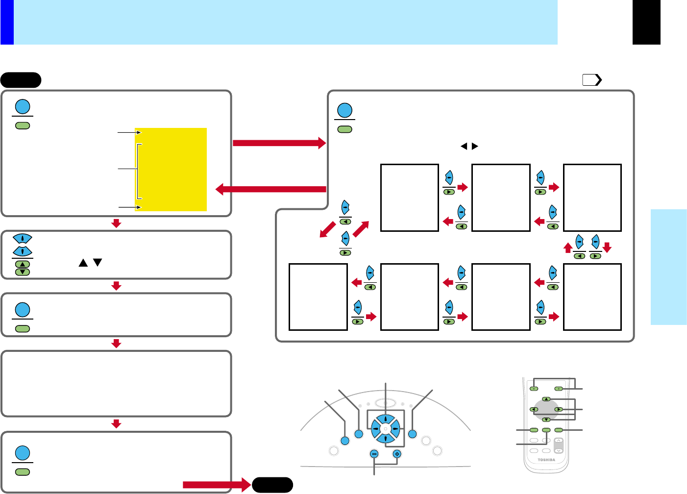
Press MENU.
Then GUIDE MENU appears, and a list of several
items is displayed in the menu.
MENU
MENU
When you make more
detailed adjustments
and settings, call the
FULL MENU.
Return to the GUIDE MENU when
the MENU button is pressed.
Press MENU button once again.
The FULL MENU of [Picture] appears.
FULL MENU has seven pages of [Picture], [Position], [Color], [Audio],
[Display], [Default setting] and [Reset].
Use the selection button ( ) to change the page of FULL MENU.
/
[Picture][Position][Color]
[Default setting]
[Reset][Display][Audio]
Select the item with the selection
button ( ).
/
ENTER
ENTER
Press ENTER to decide.
The item selected can be adjusted or set.
EXIT
EXIT
Press EXIT and return.
When you select other items, press EXIT repeatedly
until GUIDE MENU appears.
When you want to quit, press EXIT repeatedly until
GUIDE MENU disappears.
Start
FULL MENU: For the operating instruction, refer to the next page. GUIDE MENU:
You can adjust or set the functions used frequently.
Items
Button operation guide
The current input source
Adjust and set it with the button indicated
on the button operation guide.
According to the selected item, the kind ([adjustment],[setting]
or [execution]) and the button to be used are indicated on the
button operation guide.
VOL/ADJ
Selection
MENU
ENTER
EXIT
MENUENTEREXIT
PIP
FREEZE
MUTECALL
RESIZE
VOLUME/ADJUST
K
E
Y
S
T
O
N
E
A
U
T
O
S
E
T
E
X
I
T
ON / STANDBY
VOL / ADJ
E
N
T
E
R
M
E
N
U
I
N
P
U
T
F
A
N
T
E
M
P
L
A
M
P
O
N
VOL/ADJ
Selection
MENU
ENTER
EXIT
Control panel (Main unit side)
Remote control
44
Operating the menu screen
Various adjustments and settings can be made on the menu screen. The basic operation on the menu screen is shown here.
CONTENTS
44
Adjustments &
Settings
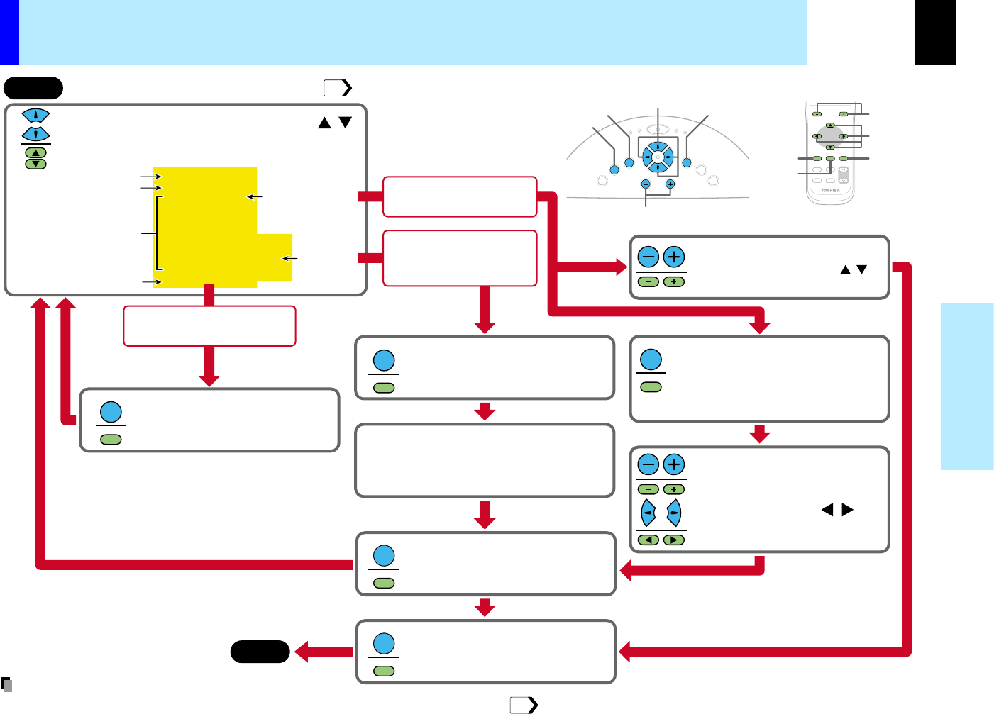
End
Select the item with selection buttons ( ).
State of a figure below is a sample for explanation.
This state does not in fact.
/
ENTER
ENTER
Press ENTER.
The Item selected is executed. FULL
MENU is displayed after execution.
ENTER
ENTER
Press ENTER.
An object can be selected from the
sub menu list.
Start
VOL/ADJ
Selection
MENU
ENTER
EXIT
MENUENTEREXIT
PIP
FREEZE
MUTECALL
RESIZE
VOLUME/ADJUST
K
E
Y
S
T
O
N
E
A
U
T
O
S
E
T
E
X
I
T
ON / STANDBY
VOL / ADJ
E
N
T
E
R
M
E
N
U
I
N
P
U
T
F
A
N
T
E
M
P
L
A
M
P
O
N
VOL/ADJ
Selection
MENU
ENTER
EXIT
Control panel (Main unit side)
Remote control
Adjustment display bar
Setting objects
Kind (page) of FULL MENU
Select it with the button indicated
on the button operation guide.
For the selection method of FULL MENU, refer to
the previous page.
ENTER
ENTER
Press ENTER.
Only the (small list of the) selected
adjusting items is displayed.
This is useful as you can see a main
picture not hidden under FULL MENU.
Adjust with VOL/ADJ (+/-) or
selection buttons ( ).
/
EXIT
EXIT
Press EXIT.
FULL MENU is displayed and you can
select other items.
EXIT
EXIT
Press EXIT.
FULL MENU disappears, and
adjustment or setting is finished.
At the item where the
adjustment bar is displayed;
At the item where the
setting objects are
displayed on sub menu;
Method -1
Method -2
Adjust with VOL/ADJ (+/-)
Press the selection button ( )
when selecting othe items continuously.
/
At the item where [Execution] is
displayed on the operation guide;
Items
Button operation guide
The current input source
Operating the menu screen (continued)
43
•An exclusive menu is displayed when making PIP function sub-picture settings.
53
Note
CONTENTS
45
Adjustments &
Settings
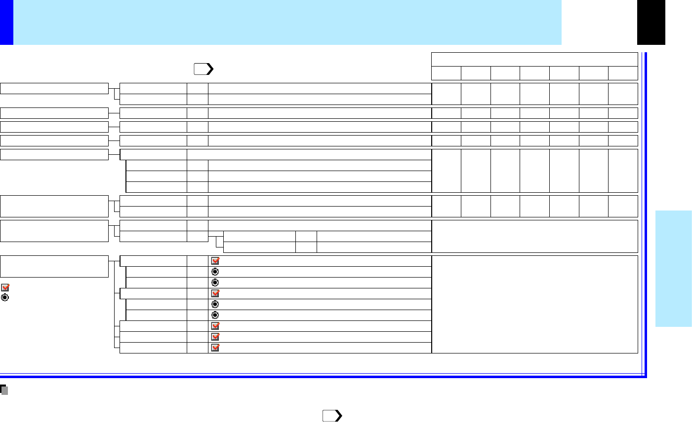
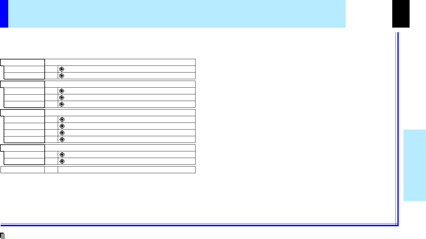
Adjust the image brightness.
Contrast
Brightness
Adjusting contrast of the picture
Adjusting brightness of the picture
ADJ.
ADJ.
Adjust the image flicker.
Phase
Adjusting flicker of the picture (sampling clock phase adjustment)
ADJ.
Select the image with its brightness
priority or quality (color) priority.
BrightPriority is given to brighter pictureSET
True colorPriority is given to the true color of the pictureSET
Correct the keystone distortion
of the screen.
Auto. V-keystoneThe vertical keystone distortion is adjusted automatically
: COMPUTER IN 1 connector is selectable by INPUT button
: COMPUTER IN 2 connector is selectable by INPUT button
EXEC.
VIDEO: Video input is selectable by INPUT buttonSET
EXEC.
To manual adjustment
Adjusting the Vertical keystoneADJ.V-keystone
Adjusting the Horizontal keystone
ADJ.
H-keystone
Select the input source when
changing the input.
SET
COMPUTER IN 1
: Use COMPUTER IN 1
connector
as Analog RGB(1) inputSETAnalog RGB(1)
: Use COMPUTER IN 1
connector
as Y/PB/PR inputSETY/PB/PR
SET
COMPUTER IN 2
: Use COMPUTER IN 2
connector
as Analog RGB(2) inputSETAnalog RGB(2)
: Use COMPUTER IN 2
connector
as Digital RGB inputSETDigital RGB
S-VIDEO: S-Video input is selectable by INPUT buttonSET
CAMERA: Camera input is selectable by INPUT buttonSET
Ye sYe sYe s
Adjust the image color.
ColorAdjusting color deepness of the pictureADJ.
Adjust the gain of the document imaging camera.
Reduce the flicker.
Camera gainAdjusting the document imaging camera's gainADJ.
Ye s------
------Yes
----
Ye s
(common for all of the inputs)
Ye s
(common for all of the inputs)
Digital RGB
Y/P
B
/P
R
Video
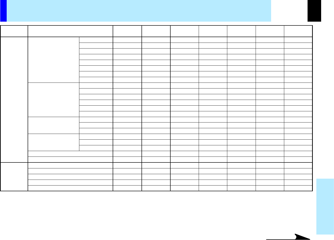
The relationship between input source and item Yes: Adjustable -: Not displayed
S-VideoCamera
Analog RGB(1)Analog RGB(2)
Select it from follows so that flickering of the document imaging camera's picture decreases
Shutter
The shutter speed is set automaticallySETAuto
The shutter speed is fixed to 50 HzSET50Hz
The shutter speed is fixed to 60 HzSET60Hz
Ye sYe sYe sYe sYe sYe sYe s
----
Ye sYe sYe s
----
YesYes-
: On/Off with ENTER
: On/Off with (+) or (-)
GUIDE MENU adjustments and settings
On GUIDE MENU, you can set or adjust the functions frequently used.
To operate GUIDE MENU, refer to page .
•The items related to the camera (the document imaging camera) are displayed only with a model having the camera.
•"Sampling phase" is to be adjusted and memorized for each RGB signal .
•"Keystone" and "Input source setting" can be adjusted (set) at all input sources, but the adjustments (settings) made at one input source are applied
to all input sources.
•It is impossible to exit from the menu if no input source is selected.
•If the check in the check box for the currently selected source is removed, the setting becomes effective the next time the input is changed.
•The adjustments or settings made are memorized automatically when the power is turned off by pressing the ON/STANDBY button. If the power cord
is unplugged or if a power failure occurs while the projector is on, the adjustments or settings are not memorized.
43
71
Notes
CONTENTS
46
Adjustments &
Settings
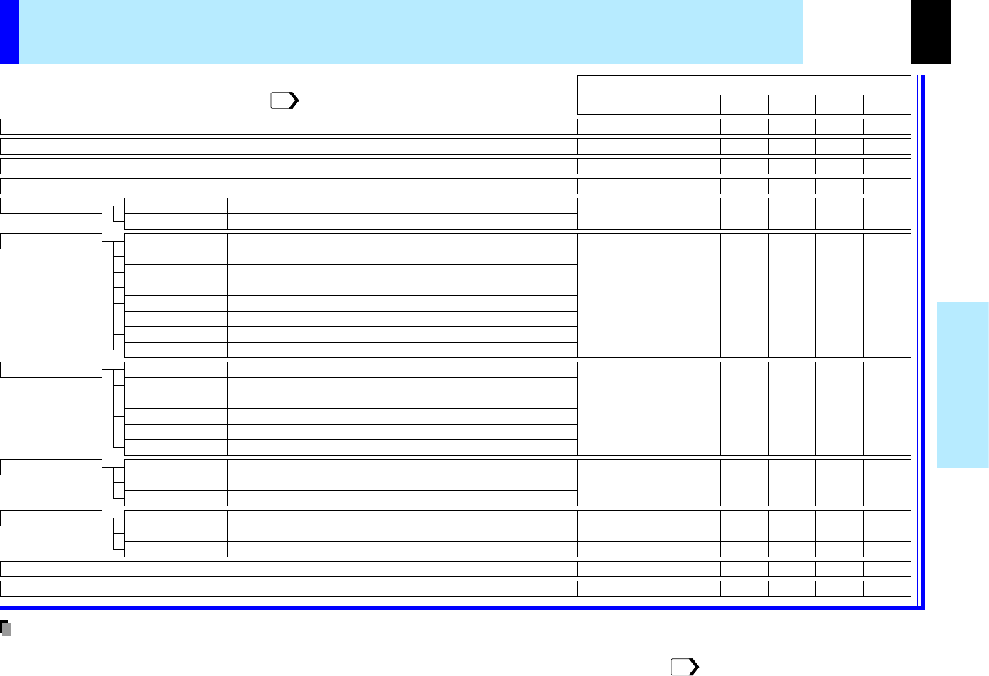
Contrast
Brightness
Adjusting contrast of the picture
Adjusting brightness of the picture
ADJ.
ADJ.
Sharpness
Adjusting sharpness of the picture (This item is setting instead of adjustment at Y/PB/PR input.)
ADJ.
Picture modeBrightPriority is given to brighter pictureSET
True colorPriority is given to the true color of the pictureSET
Camera gainAdjusting the document imaging camera's gainADJ.
------
Overlay gainAdjusting the level of the overwriting picture using the document imaging cameraADJ.
Reset
The adjustments and settings of FULL MENU [Picture] are returned to the factory default setting
EXEC.
----
Video modeAuto
The video mode (color system) is set automatically
SET
NTSC
The video mode is fixed to NTSC system
SET
PAL
The video mode is fixed to
PAL systemSET
SECAM
The video mode is fixed to
SECAM systemSET
PAL-N
The video mode is fixed to
PAL-N systemSET
PAL-M
The video mode is fixed to
PAL-M systemSET
PAL-60
The video mode is fixed to
PAL-60 systemSET
NTSC-4.43
The video mode is fixed to
NTSC-4.43 systemSET
Signal formatAutoThe Y/P
B
/P
R
signal format is set automaticallySET
525iThe Y/P
B
/P
R
signal format is fixed to 525i modeSET
525pThe Y/P
B
/P
R
signal format is fixed to 525p modeSET
625iThe Y/P
B
/P
R
signal format is fixed to 625i modeSET
750pThe Y/P
B
/P
R
signal format is fixed to 750p modeSET
1125iThe Y/P
B
/P
R
signal format is fixed to 1125i modeSET
ShutterAuto
The
shutter speed
is set automatically
SET
50Hz
The
shutter speed
is fixed
to 50 HzSET
60Hz
The
shutter speed
is fixed
to 60 HzSET
----
Screen sizeFull
The picture is converted to XGA (1024 x 768 dot) resolution
SET
thru
The picture is displayed with the input resolution
SET
Wide
The picture is converted to the wide screen picture
SET
Digital RGB
Y/P
B
/P
R
Video
The relationship between input source and item Yes: Adjustable -: Not displayed
S-VideoCamera
Analog RGB(1)Analog RGB(2)
Ye sYe sYe sYe sYe sYe sYe s
Ye sYe sYe sYe sYe sYe sYe s
Ye s
-
------
Ye s
Ye sYe sYe sYe sYe sYe sYe s
Ye sYe sYe sYe sYe sYe s
Ye sYe sYe s
Ye sYe sYe sYe sYe sYe sYe s
------
Ye s
---
Ye sYe sYe s
-----
Ye sYe s
Ye s
Ye sYe sYe s
FULL MENU adjustments and settings - Picture
You can adjust various items of the picture from FULL MENU [Picture].
To operate FULL MENU, refer to page .
44
•The items related to the camera are indicated only with a model having the camera.
•A part of function is restricted if the object other than [Auto] is selected in "Video mode" or "Signal format".
•The adjustments or settings made are memorized automatically when the power is turned off by pressing the ON/STANDBY button. If the power cord
is unplugged or if a power failure occurs while the projector is on, the adjustments or settings are not memorized.
51
Notes
CONTENTS
47
Adjustments &
Settings
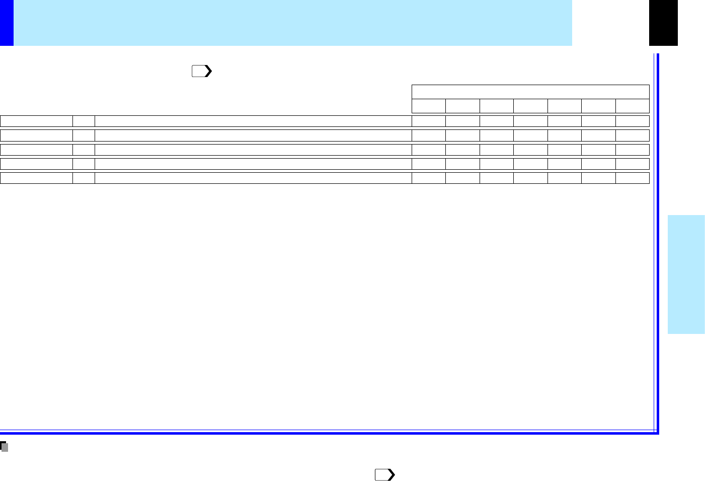
H-position
V-position
Adjusting the horizontal display position of the picture
Adjusting the vertical display position of the picture
ADJ.
ADJ.
PhaseAdjusting flicker of the picture (sampling clock phase adjustment)ADJ.
Frequency
Adjusting the sampling frequency of the input signalADJ.
ResetThe adjustments of FULL MENU [Position] are returned to the factory default value
EXEC.
----
YesYes-
----
YesYes-
----
YesYes-
----
YesYes-
----
YesYes-
Digital RGB
Y/P
B
/P
R
Video
The relationship between input source and item Yes: Adjustable -: Not displayed
S-VideoCamera
Analog RGB(1)Analog RGB(2)
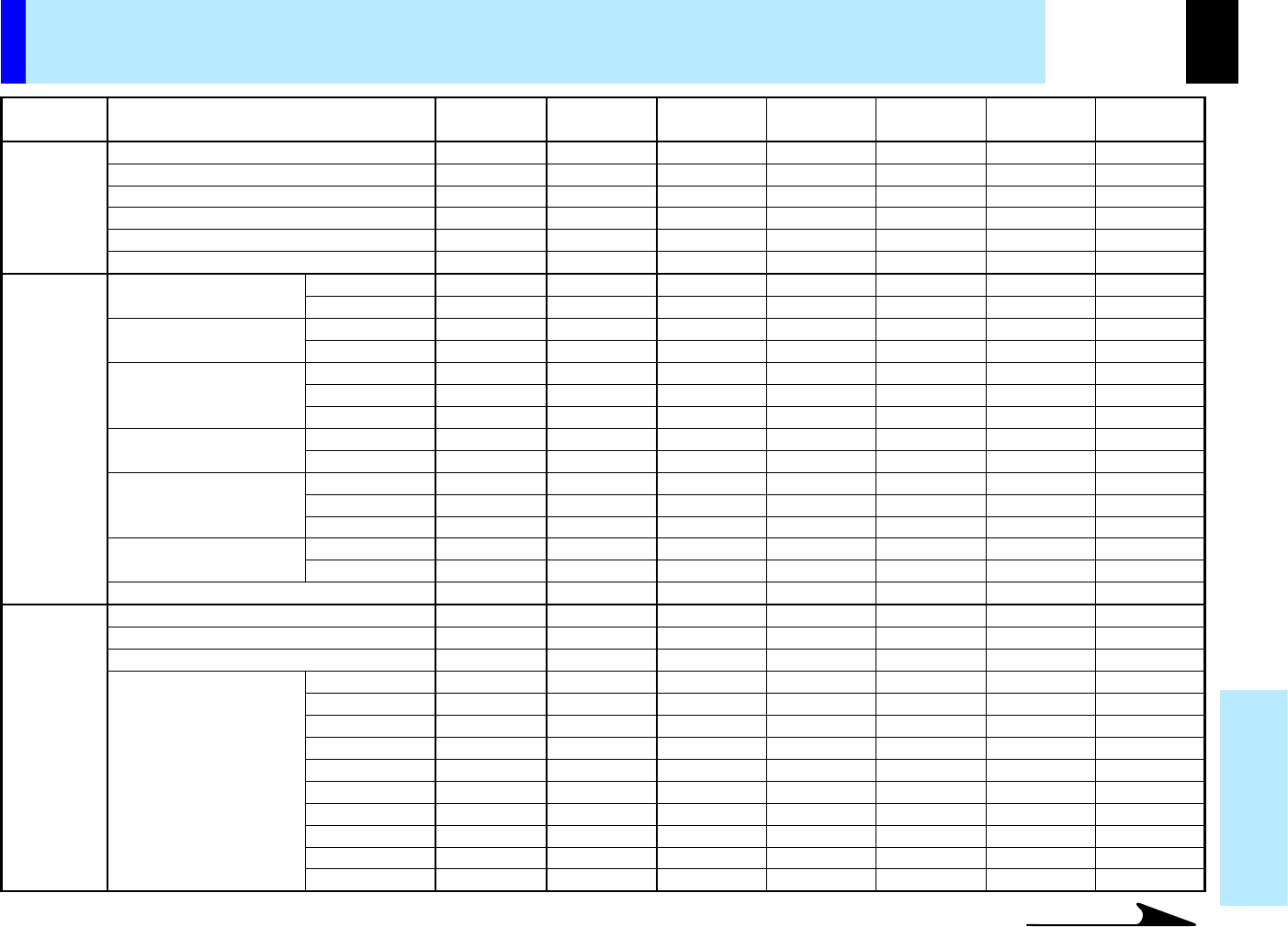
FULL MENU adjustments - Position
•This menu is not displayed except analog RGB input.
•The adjustment of each item in this menu is memorized for each RGB signal input .
•The adjustments made are memorized automatically when the power is turned off by pressing the ON/STANDBY button. If the power cord is
unplugged or if a power failure occurs while the projector is on, the adjustments are not memorized.
You can adjust the picture position etc. of analog RGB input from FULL MENU [Position].
To operate FULL MENU, refer to page .
44
71
Notes
CONTENTS
48
Adjustments &
Settings
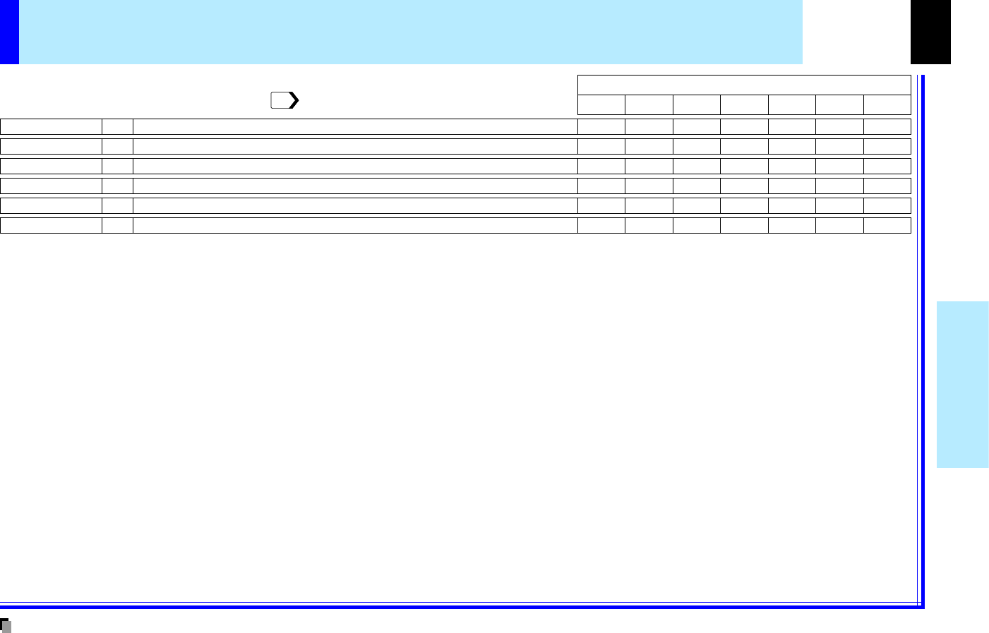
Color
Tint
Adjusting color deepness of the picture
Adjusting tint of the picture (not adjustable at PAL, SECAM, PAL-N,PAL-M and PAL60)
ADJ.
ADJ.
R-levelAdjusting red's color level of the pictureADJ.
G-levelAdjusting green's color level of the pictureADJ.
B-levelAdjusting blue's color level of the pictureADJ.
ResetThe adjustments of FULL MENU [Color] are returned to the factory default value
EXEC.
Ye sYe sYe sYe sYe sYe sYe s
Ye sYe sYe sYe sYe sYe sYe s
Ye sYe sYe sYe sYe sYe sYe s
Ye sYe sYe sYe sYe sYe sYe s
----YesYes
-
-Yes--YesYes
-
Digital RGB
Y/P
B
/P
R
Video
The relationship between input source and item Yes: Adjustable -: Not displayed
S-VideoCamera
Analog RGB(1)Analog RGB(2)
FULL MENU adjustments - Color
•The adjustments made are memorized automatically when the power is turned off by pressing the ON/STANDBY button. If the power cord is
unplugged or if a power failure occurs while the projector is on, the adjustments are not memorized.
You can adjust the color condition of the picture from FULL MENU [Color].
To operate FULL MENU, refer to page .
44
Notes
CONTENTS
49
Adjustments &
Settings
VolumeAdjusting the sound volume developed from speakerADJ.
Speaker outputOnThe sound is developed from the speakersSET
OffNo sound is developed from the speakersSET
Reset
The adjustments and settings of FULL MENU [Audio] are returned to the factory default setting
EXEC.
-
-
-
LoudnessOnThe loudness effect is added to the speaker soundSET
OffThe loudness effect is not added to the speaker soundSET
Ye s
(common)
Ye s
(common)
Ye s
(common)
Ye s
(common)
Ye s
(common)
Ye s
(common)
Ye s
(common)
Ye s
(common)
-
Channel selectL+R
The sound of the left and right channels is mixed and developed from the speaker
SET
L
Only the sound of the left input channel is developed from the speaker
SET
R
Only the sound of the right channel is developed from the speaker
SET
Ye sYe sYe sYe sYe sYe s-
Digital RGB
Y/P
B
/P
R
Video
The relationship between input source and item Yes: Adjustable -: Not displayed
S-VideoCamera
Analog RGB(1)Analog RGB(2)
FULL MENU adjustments and settings - Audio
•When the camera input is selected, the sound is not developed.
•
Each item can be set at every input sources except the camera input, but the settings made at one input source are applied to all input sources as shown
in the table. The sound volume can be adjusted for each input source except the camera input.
•The adjustments or settings made are memorized automatically when the power is turned off by pressing the ON/STANDBY button. If the power cord
is unplugged or if a power failure occurs while the projector is on, the adjustments or settings are not memorized.
You can set the sound developed from the speaker from FULL MENU [Audio].
To operate FULL MENU, refer to page .
44
Notes
CONTENTS
50
Adjustments &
Settings
V-keystoneAdjusting the keystone distortion when having changed the vertical installation angleADJ.
Language
English
The language is set to English for menu and message displayed
SET
Français
The language is set to French for menu and message displayed
SET
IconOn
Off
Reset
The adjustments and settings of FULL MENU [Display] are returned to the factory default setting
EXEC.
Português
The language is set to Portuguese for menu and message displayed
SET
The language is set to Japanese for menu and message displayed
SET
H-keystone
Adjusting the keystone distortion when having changed the horizontal installation angle
ADJ.
Deutsch
The language is set to German for menu and message displayed
SET
Italiano
The language is set to Italian for menu and message displayed
SET
Español
The language is set to Spanish for menu and message displayed
SET
The language is set to Chinese (Simplified) for menu and message displayed
SET
The language is set to Chinese (Traditional) for menu and message displayed
SET
The language is set to Korean for menu and message displayed
SET
The icon is displayed
SET
The icon is not displayed
SET
Menu translucent
On
Off
The menu background becomes translucent
SET
The menu background in normal state
SET
Menu positionUpper left
Upper right
The menu is displayed to upper left on the screen
SET
The menu is displayed to upper right on the screen
SET
Bottom left
The menu is displayed to bottom left on the screen
SET
Bottom right
The menu is displayed to bottom right on the screen
SET
Ye s
(common for all of the inputs)
Ye s
(common for all of the inputs)
Ye s
(common for all of the inputs)
Ye s
(common for all of the inputs)
Ye s
(common for all of the inputs)
Ye s
(common for all of the inputs)
Ye s
(common for all of the inputs)
Digital RGB
Y/P
B
/P
R
Video
The relationship between input source and item Yes: Adjustable -: Not displayed
S-VideoCamera
Analog RGB(1)Analog RGB(2)
FULL MENU adjustments and settings - Display
•Each item can be set at all input sources, but the settings made at one input source are applied to all input sources.
•The adjustments or settings made are memorized automatically when the power is turned off by pressing the ON/STANDBY button. If the power cord
is unplugged or if a power failure occurs while the projector is on, the adjustments or settings are not memorized.
You can set the language, menu display, etc. from FULL MENU [Display].
To operate FULL MENU, refer to page .
44
Notes
CONTENTS
51
Adjustments &
Settings
ResetThe settings of FULL MENU [Default setting] are returned to the factory default setting
EXEC.
Projection modeStandard
The projector placement is set to the floor-mounted front projection mode
SET
Rear
The projector placement is set to the floor-mounted rear projection mode
SET
Ceiling
The projector placement is set to the ceiling-mounted front projection mode
SET
Rear ceiling
The projector placement is set to the ceiling-mounted rear projection mode
SET
No signal background
Logo
The TOSHIBA logo is displayed when no signal is input
SET
Blue background
A blue color is displayed at full screen when no signal is input
SET
None
Nothing is displayed when no signal is input
SET
No signal power off
Off
The projector continues work even if the no signal status continues
SET
5 min.
The power turns off automatically if the no signal status continues for approx. 5 min.
SET
: COMPUTER IN 1 connector is selectable by INPUT button
: COMPUTER IN 2 connector is selectable by INPUT button
VIDEO: Video input is selectable by INPUT buttonSET
Input source setting
SETCOMPUTER IN 1
: Use COMPUTER IN 1
connector
as Analog RGB(1) inputSETAnalog RGB(1)
: Use COMPUTER IN 1
connector
as Y/P
B
/P
R
inputSETY/P
B
/P
R
SETCOMPUTER IN 2
: Use COMPUTER IN 2
connector
as Analog RGB(2) inputSETAnalog RGB(2)
: Use COMPUTER IN 2
connector
as Digital RGB inputSETDigital RGB
S-VIDEO: S-Video input is selectable by INPUT buttonSET
CAMERA: Camera input is selectable by INPUT buttonSET
Ye s
(common for all of the inputs)
Ye s
(common for all of the inputs)
Ye s
(common for all of the inputs)
Ye s
(common for all of the inputs)
Power onManual
The power turns on by pressing the ON/STANDBY button
SET
Auto
When the power cord is plugged, the power turns on
SET
Ye s
(common for all of the inputs)
Startup screenOn
The opening picture is displayed when the power is turned on
SET
Off
The opening picture is not displayed when the power is turned on
SET
Ye s
(common for all of the inputs)
Ye s
(common for all of the inputs)
Digital RGB
Y/P
B
/P
R
Video
The relationship between input source and item Yes: Adjustable -: Not displayed
S-VideoCamera
Analog RGB(1)Analog RGB(2)
: On/Off with ENTER
: On/Off with (+) or (-)
FULL MENU settings - Default setting
•It is impossible to exit from the menu if no input source is selected.
•If the check in the check box for the currently selected source is removed, the setting becomes effective the next time the input is changed.
•In the following conditions, the function to detect no signal ("No signal background", "No signal power off") does not act:
1) When "Video mode" is set to other than [Auto] with selection of Video input or S-Video input.
2) When "Signal format" is set to other than [Auto] with selection of Y/PB/PR input.
•Note that the projector automatically turns on at the restoration from power failure, if "Power on" is set to [Auto] with the power cord being pluged, even
if it is not intended to.
•Even if "Power on" is set to [Auto], the setting of [5 min.] of "No signal power off" is effective.
•Each item can be set at all input sources, but the settings made at one input source are applied to commonness for all input sources.
•The settings made are memorized automatically when the power is turned off by pressing the ON/STANDBY button. If the power cord is un-
plugged or if a power failure occurs while the projector is on, the settings are not memorized.
Notes
You can set the Input source, projection mode, etc. from FULL MENU [Default setting].
To operate FULL MENU, refer to page .
44
46
46
CONTENTS
52
Adjustments &
Settings
Reset allThe adjustments and settings of all menus are returned to the factory default setting
EXEC.
H-reference resetThe horizontal reference value for "Auto. V-keystone" is calibrated automatically
EXEC.
FULL MENU settings - Reset
•If the projector's foot adjuster is used or the projector is inclided, "H-reference reset" will not be executed properly.
•The settings made are memorized automatically when the power is turned off by pressing the ON/STANDBY button. If the power cord is un-
plugged or if a power failure occurs while the projector is on, the settings are not memorized.
•You can return the adjusting and setting value of all menus to the factory default setting. ("H-reference value" below also returns to the value at the
factory default setting.)
•The projector stores the standard conditions of horizontal installation, but depending on the usage environment (if the projector is subject to
vibrations or shock, etc.), the standard may change.
If the keystone distortion is not corrected properly when "Auto. V-keystone" is executed with the screen installed vertically, put the projector's
foot adjustor back and set the projector on a flat surface, then execute "H-reference reset"
20
35
Notes
CONTENTS
53
Adjustments &
Settings
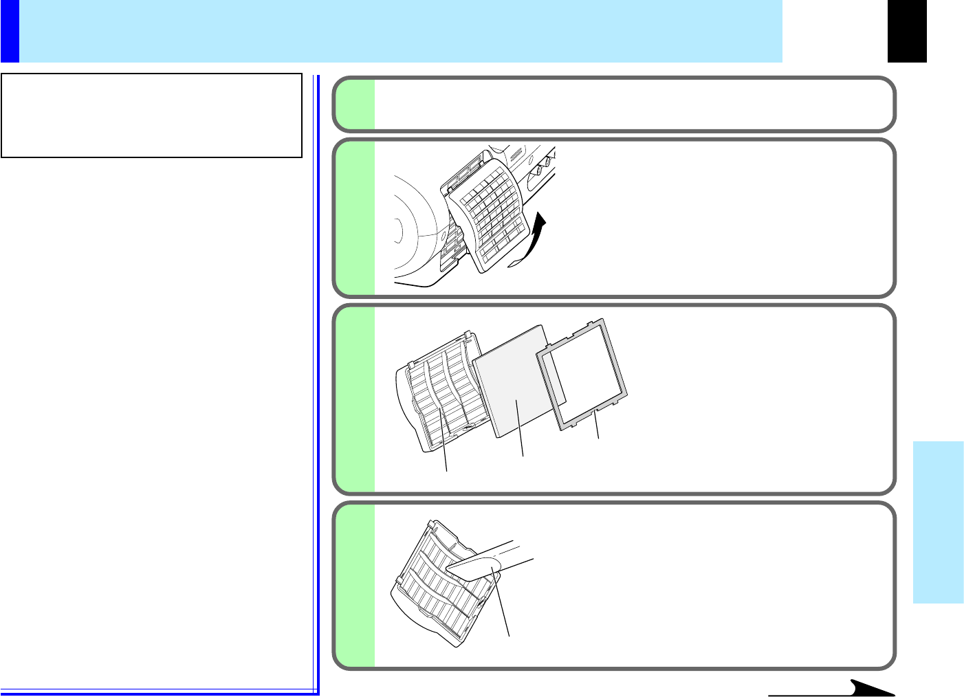
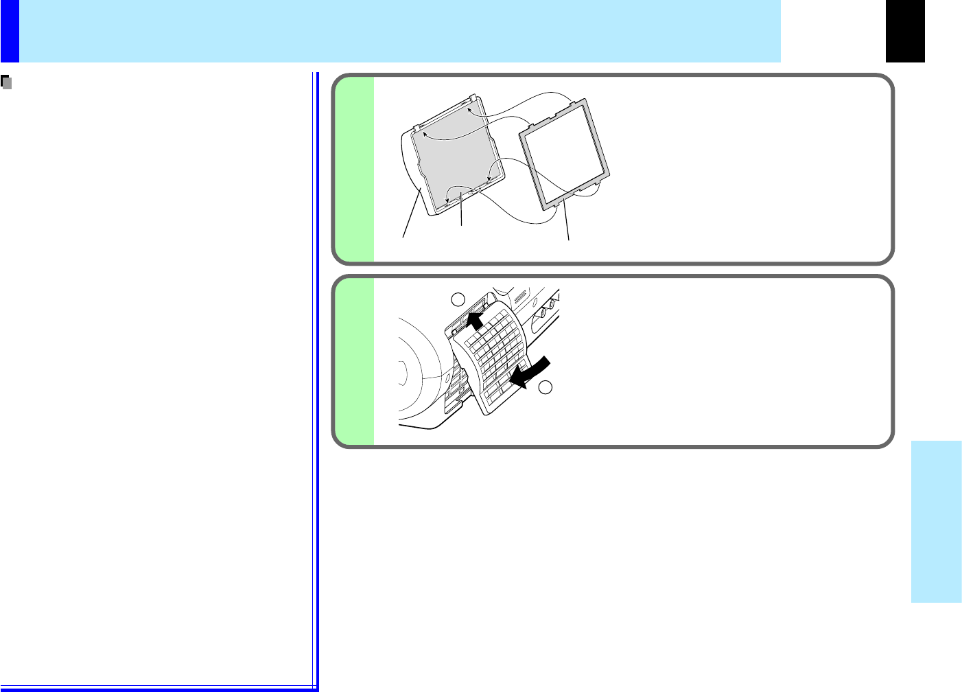
Reset
The settings of PIP MENU are returned to the factory default setting
EXEC.
Selecting the signal source for PIP sub-picture
Setting of the PIP sub-picture size
Source
: Video input is selected as signal sourceSETVideo
: S-Video input is selected as signal sourceSETS-Video
Size
: The PIP sub-picture size is set to smallSETSmall
: The PIP sub-picture size is set to middleSETMiddle
Selecting the audio input sourceAudio
: The main picture's sound is developed from the speakerSETMain
: The sub picture's sound is developed from the speakerSETSub
: The PIP sub-picture size is set to largeSETLarge
Setting of the PIP sub-picture display positionPosition
:
The sub-picture is displayed to upper left on the screen
SETUpper left
:
The sub-picture is displayed to upper right on the screen
SETUpper right
:
The sub-picture is displayed to bottom left on the screen
SETBottom left
:
The sub-picture is displayed to bottom right on the screen
SETBottom right
PIP menu setting
When a PIP sub-picture is displayed, the PIP menu screen appears.
You can make the PIP sub-picture settings and the sound settings when a PIP subpicture is displayed.
To cancel the menu, press EXIT.
•
The size of the PIP sub-picture changes according to the signal type (resolution) of the main picture.
•When the PIP sub-picture is turned off, the audio input source returns to the previous source (main picture).
•
The settings made are memorized automatically when the power is turned off by pressing the ON/STANDBY button. If the power cord is unplugged or if
a power failure occurs while the projector is on, the settings are not memorized.
Notes
CONTENTS
54
Document
imaging camera
STORE
CAMERA
ARM LIGHT
LOCK
W.BALANCE
GAIN
FOCUS
OVERLAY
CAMERA
ARM LIGHT
LOCK
W.BALANCE
CAMERA
GAIN
Part names (of the document imaging camera model)
CAUTION
When using the camera, be careful not to
pinch your hand or fingers into the arm.
On the document imaging camera model, you can
project pictures using the document imaging camera.
The document imaging camera can directly project any
materials (documents, illustrations, etc.) without using
an OHP film.
Camera control panel
Focusing ring
LED light
Infrared remote sensor
Camera lens
Camera head
Arm
LOCK (W.BALANCE) indicator
Lights when the white balance is locked.
W.BALANCE button
To switch white balance settings between automatic
adjustment and lock.
ARM LIGHT button
To turn on or off the light.
CAMERA button
To select the camera source. Press again
to return to the previous input source.
CAMERA GAIN (+/-) button
To adjust the camera gain.
OVERLAY button
To turn on or off the overlay function.
60
60
59
56
57
58
57
16
CONTENTS
55
Document
imaging camera
STORE
CAMERA
ARM LIGHT
LOCK
W.BALANCE
GAIN
FOCUS
STORE
CAMERA
ARM LIGHT
LOCK
W.BALANCE
GAIN
FOCUS
STORE
CAMERA
ARM LIGHT
LOCK
W.BALANCE
GAIN
F
OCUS
STORE
CAMERA
ARM LIGHT
LOCK
W.BALANCE
GAIN
FOCUS
STORE
CAMERA
ARM LIGHT
LOCK
W.BALANCE
GAIN
FOCUS
1) Raise up the arm.
Before preparations
(stowed away)
2) Stretch the arm.3) Turn the arm.
4) Open the camera head.5) Turn the camera head.6) Pull up the light.7) Turn the light.
STORE
CAMERA
ARM LIGHT
LOCK
W.BALANCE
GAIN
FOCUS
STORE
CAMERA
ARM LIGHT
LOCK
W.BALANCE
GAIN
Preparation of the document imaging camera
•Never give shocks or impacts to the camera or arm as this may cause malfunction.
•While raising up or turning the arm, the arm moves describing an arc, be careful not to hit your face or your body.
•The figures above are procedures of putting materials on the projector. When the stability of materials is required, place the materials at the back of
the projector and set the arm and camera head for them.
Notes
CONTENTS
56
Document
imaging camera
2
1
1
123123
123
123
ARM LIGHT
OVERLAY
CAMERA
ARM LIGHT
LOCK
W.BALANCE
CAMERA
GAIN
1
FOCUS
FOCUS
STORE
CAMERA
ARM LIGHT
LOCK
W.BALANCE
GAIN
FO
CU
S
123
123
STORE
CAMERA
ARM LIGHT
LOCK
W.BALANCE
GAIN
FOCUS
28
You can also place the materials at the
back of the projector and move the arm
and the camera head for them.
Setting direction
Images on the screen
Camera control panel
Press ARM LIGHT.
The light turns on.
Set a document to be projected.
Place the document (illustrations, etc.) onto or around the
projector, and turn the camera head to the direction of the
document.
•Use the arm light according to the brightness of the room when necessary.
•When setting the materials on the projector, be careful not press the operation buttons.
Picture projection with the document imaging camera
CAUTION
Do not look into the arm light while it is lit.
Preparation
Project a picture on the screen as explained in the step "Projection on the screen".
Continued
Notes
CONTENTS
57
Document
imaging camera
K
E
Y
S
T
O
N
E
A
U
T
O
S
E
T
E
X
I
T
ON / STANDBY
VOL / ADJ
E
N
T
E
R
M
E
N
U
I
N
P
U
T
F
A
N
T
E
M
P
L
A
M
P
O
N
4
3
3
CAMERA
INPUT
INPUT
5
FOCUS
3
3
OVERLAY
CAMERA
ARM LIGHT
LOCK
W.BALANCE
CAMERA
GAIN
MENU
ON/STANDBYINPUT
L-CLICKR-CLICK
ENTER
KEYSTONE
AUTO
SET
EXIT
PIP
FREEZE
MUTECALL
RESIZE
VOLUME/ADJUST
LASER
STORE
CAMERA
ARM LIGHT
LOCK
W.BALANCE
GAIN
F
OCUS
123
Press CAMERA to select the camera input
mode.
• You can also select it by pressing INPUT on the remote
control or on the main unit. Set the input source on the
menu screen when selecting by the INPUT button.
• The CAMERA button can be used regardless of the input
setting.
• "Camera" is displayed when the picture switches to the
document imaging camera's picture.
Move the camera head to adjust the size of
the picture.
Up: To reduce.
Down: To enlarge.
Focus on the picture by turning the focusing
ring on the camera head.
Focusing ring
Continued
Picture projection with the document imaging camera (continued)
Remote control
Control panel
(Main unit side)
Camera control panel
30
CONTENTS
58
Document
imaging camera
OVERLAY
CAMERA
ARM LIGHT
LOCK
W.BALANCE
CAMERA
GAIN
6
7
CAMERA
GAIN
6
Press CAMERA GAIN (+/-) to improve view
of a camera subject which is too dark or vivid.
When finished, turn off the light and close it,
and put back the arm.
Follow the steps of "Preparation of the document imaging
camera" in reverse.
•You can adjust the "Sharpness" of the camera image on the menu screen.
•If the image flickers due to a fluorescent light in the room, either turn off the fluorescent light
or set the "Shutter" from the menu screen.
Note that the image may still flicker due to the lighting, the document status, the image
adjustment, etc., even if the "Shutter" setting is changed.
•Though this projector uses a 1.45 million pixel camera unit, the images projected on the
screen are 1024 x 768 dot images. If the "Screen size" in the menu screen is set to
"Full" the camera's full image is compressed to 1024 x 768 dots. If "Thru" is selected, the
1024 x 768 dots at the center of the image are projected.
•The light turns off automatically when the arm is leaned.
•When the arm is not raised up, the camera source cannot be projected.
•In the camera input selected, audio signals are not output.
Picture projection with the document imaging camera (continued)
Camera control panel
46
46
46
Notes
Notes
CONTENTS
59
Document
imaging camera
K
E
Y
S
T
O
N
E
A
U
T
O
S
E
T
E
X
I
T
ON / STANDBY
VOL / ADJ
E
N
T
E
R
M
E
N
U
I
N
P
U
T
F
A
N
T
E
M
P
L
A
M
P
O
N
1
2
OVERLAY
3
1
2
INPUT
INPUT
4
RGB picture
2
3
OVERLAY
CAMERA
ARM LIGHT
LOCK
W.BALANCE
CAMERA
GAIN
2
MENU
ON/STANDBYINPUT
L-CLICKR-CLICK
ENTER
KEYSTONE
AUTO
SET
EXIT
PIP
FREEZE
MUTECALL
RESIZE
VOLUME/ADJUST
LASER
STORE
CAMERA
ARM LIGHT
LOCK
W.BALANCE
GAIN
FOCU
S
Overlaying projection
•Handwriting in colors except blue and red cannot be displayed properly.
•Handwriting in fine lines may not be displayed properly.
•The depth overwritten can be adjusted from the menu screen.
Select the input source using the overlay
function by pressing INPUT.
Select the input source other than the camera input.
Set the white paper on a flat place
and set the camera so that paper is
projected to the full screen.
The white paper should be projected fully on the
screen.
Press OVERLAY
Draw any line on the paper with a red
or blue pen.
A drawn line is projected on the screen, overlapped
with the picture of the input source.
The position of a pen point can be confirmed on the
screen before drawing anything.
Screen
Paper
46
You can draw figures or letters with a pen on the
picture of RGB input or video input, by using the
overlaying function.
Remote control
Control panel
(Main unit side)
Camera control panel
Preparation
Project a picture on the screen as explained in the step "Picture projection with the
document imaging camera".
Prepare white paper and a red or blue pen.
56
Notes
CONTENTS
60
Document
imaging camera
STORE
CAMERA
ARM LIGHT
LOCK
W.BALANCE
GAIN
F
OC
U
S
OVERLAY
CAMERA
ARM LIGHT
LOCK
W.BALANCE
CAMERA
GAIN
2
1
2
LOCK
W.BALANCE
This projector's camera is always being adjusted automatically for projected color
balance;
however, the balance can shift away from optimal due to the color scheme of the
document. Should this occur, the white balance can be set to a fixed condition by
using the following procedure.
Project a white paper and enlarge it to fill the
screen.
Press W.BALANCE to turn the LOCK indicator
on.
The white balance is locked.
To release the white balance, press W.BALANCE again to
turn the LOCK indicator off.
•If you raise up the arm while the camera input is selected, the color of the picture may vary
for an instant due to the automatic white balance adjustment. This is not a malfunction.
•If you put back the arm and raise it up while the white balance is locked (the LOCK indicator
is lit), the projector releases the white balance.
•Should this be the case, or if you would like to adjust to a desired tint, adjust "R-level", "G-
level" or "B-level" on the FULL MENU [Color] screen.
Lock the white balance
Camera control panel
Notes
CONTENTS
61
Document
imaging camera
K
E
Y
S
T
O
N
E
A
U
T
O
S
E
T
E
X
I
T
ON / STANDBY
VOL / ADJ
E
N
T
E
R
M
E
N
U
I
N
P
U
T
F
A
N
T
E
M
P
L
A
M
P
O
N
FOCUS
1
2
ARM LIGHT
EXIT
2
OVERLAY
CAMERA
ARM LIGHT
LOCK
W.BALANCE
CAMERA
GAIN
For the CCD image sensor used in the camera unit, in rare cases some of the pixels
may be disturbed due to the influence of cosmic rays, etc. This disturbance may
cause white spots to appear on the picture.
If white spots appear on the document camera image, use the procedure described
below to correct it.
With the document camera operating, fully
cover the camera lens with a piece of black
paper or cloth.
Press ARM LIGHT on the camera control
panel and EXIT on the projector's control
panel simultaneously.
You can not use the remote control buttons.
•Do not press ARM LIGHT and EXIT buttons simultaneously if the camera lens is not
covered. Doing so will not only erase the white spot correction data already set but also
result in parts that are displayed normally being corrected. Also be careful if the camera
input mode is not selected.
Press both sides
Camera lens
Correcting illuminated defects
Control panel
(Main unit side)
Camera control panel
Note
CONTENTS
62
Maintenance
K
E
Y
S
T
O
N
E
A
U
T
O
S
E
T
E
X
I
T
ON / STANDBY
VOL / ADJ
E
N
T
E
R
M
E
N
U
I
N
P
U
T
F
A
N
T
E
M
P
L
A
M
P
O
N
Or
(Lit in red)
(Off)
ON
LAMP
TEMP
FAN
(Lit in red)
(Lit in red)
ON
LAMP
TEMP
FAN
(Flashing
in orange)
ON
LAMP
TEMP
FAN
(Lit in red)
ON
LAMP
TEMP
FAN
(Lit in red)
Or
(Lit or flashing
in red)
(Lit or flashing
in orange)
Or
Or
Or
(Lit in red)
(Lit in red)
(Lit in green)
(Lit in green)
(Lit in orange)
ON
LAMP
TEMP
FAN
(off)
The power does not come on.
→Malfunction of the unit.
•Unplug the power cord and call the dealer.
The lamp turns off or does not light up.
→The projector will return to the standby mode in about 2 minutes.
If the projector does not operate normally when the power is switched on again,
the lamp is at the end of its duration life or the unit has a fault.
•Lamp's duration life is over, replace the lamp with a new one.
•Unplug the power cord and call the dealer.
The power turns off or does not come on.
→ The inside is too hot, or the projector has been working in an area of high
temperature.
•Place the projector correctly so the intake and exhaust fan's holes are notcovered.
•Turn the projector off, and leave it for a while, and turn it on again.
•Clean the air filter.
* The icon appears before the power turned off.
* The projector returns to the standby mode after the fault display has been shown
for about 2 minutes.
The power turns off or does not come on.
→ Trouble with the cooling fan.
•Unplug the power cord and call the dealer.
* The icon appears before the power turned off.
* The projector returns to the standby mode after the fault display has been shown
for about 2 minutes.
The power turns off or does not come on.
→The lamp cover is not properly attached.
•Unplug the power cord and reattach the lamp cover.
* The icon appears before the power turned off.
* The projector returns to the standby mode after the fault display has been shown
for about 2 minutes.
If there is some problem inside the
projector, the indicators light up or blink.
Trouble indications
•If abnormality occurs while operating, unplug the power cord.
•When reinserting the power cord before the lamp has cooled, please wait until the lamp has cooled
sufficiently before use. When the lamp is at a high temperature, it may not light and the duration life will
be shortened.
Indicators
Control panel
(Main unit side)
66
63
67
Notes
CONTENTS
63
Maintenance
1
2
3
4
Continued
Air filter cleaning
CAUTION
If you use the projector mounted on the ceiling,
ask the dealer to carry out the maintenance such
as cleaning.
The filter inside the air filter cover is the part
to shut out dusts or dregs.
Do not use the projector with the filter taken
off.
We recommend you to clean the air filter
frequently. (The cleaning period is once per
about 50 hours).
Unplug the power cord.
Clean the air filter.
Use a vacuum cleaner to carefully remove any
dust and dirt from the air filter cover, air filter and
filter frame.
Be careful that the air filter is not sucked into the
vacuum cleaner.
Detach the air filter.
Detach the air filter from the air
filter cover.
The air filter cover, air filter and
filter frame can be disassembled.
Filter frame
Air filter
Cleaner's nozzle
Air filter cover
Take off the air filter cover.
The filter is on the right side of the projector.
Pull the bottom side of the cover upward to
remove the filter cover.
CONTENTS
64
Maintenance
6
5
2
1
Air filter cleaning (continued)
•When the air filter is dusty, the ventilation is
impaired. This causes the temperature inside
the projector to rise, and may damage the unit.
•Attach the air filter cover firmly after the
cleaning. If it is not set correctly, the dusts will
enter and they will be projected and overlapped
on the picture.
•If you wash the air filter with water, be sure to let
it dry fully before reinstalling it. Using it damp will
result in malfunction.
•If the air filter is damaged, contact your store of
purchase and replace it with a new one. Using a
damaged air filter will cause dust or dirt to get
inside the projector and onto the images.
Assemble the air filter.
Place the air filter in the air filter cover,
then insert the four tabs on the filter
frame into the holes in the air filter
cover.
Filter frame
Air filter
Air filter cover
Mount the air filter cover.
Insert the top of the air filter cover into the
projector first, then press on the bottom side
to install it.
Notes
CONTENTS
65
Maintenance
Lens and main unit cleaning
Cleaning the lens
•Use a blower or a lens cleaner to clean the lens.
•Never rub or tap the lens with a hard object as the
lens surface is fragile.
Cleaning the main unit
•Pull out the power cord before cleaning.
•Use a soft cloth to wipe off stains from the surface.
•To remove difficult stains, use a soft cloth slightly
moistened with a weak solution of synthetic
detergent and water, and finish with a soft, dry
cloth.
Replacing the intake, exhaust fans and air filter
To maintain the efficiency of the projector, replace the intake and exhaust fans
about every two to three years.
Ask the dealer for the replacement.
CAUTION
If you use the projector mounted on the ceiling,
ask the dealer to carry out the maintenance such
as cleaning.
CONTENTS
66
Maintenance
1
3
2
4
2
1
2
1
Continued
Lamp replacement
CAUTION
•If you use the projector mounted on the ceiling,
ask the dealer to carry out the maintenance
such as cleaning or replacement of the lamp.
• When replacing, always use lamp "TLPL78"
(sold separately). For detail, refer to the lamp
instruction.
•If you have been using the projector, the lamp
will be very hot, and may cause burn injuries.
Wait for the lamp to cool (for longer than 1 hour)
before replacing it.
•If the lamp should break, please handle with
care to avoid injury due to broken pieces and
contact your dealer for repair service.
The lamp will eventually begin to project dark or
dull pictures and finally will not light up.
(Lamp's life length depends on the use condition.)
In such a case, replace the lamp with new one.
Unplug the power cord.
Wait until the lamp gets cold enough.
Take off the lamp cover on the
bottom panel.
Loosen two screws, and pull off the lamp cover.
Lamp cover
Pull out the lamp.
Loosen the two fixing screws, and lift up the handle
to pull out the lamp.
CONTENTS
67
Maintenance
5
6
7
3
2
1
Lamp replacement (continued)
•When the CALL button is pressed, the "Lamp
time" (the approximate amount of time the lamp
has been used) is displayed.
•The lamp should be replaced if the total work-
ing time exceeds about 1,000 hours.
When the "Lamp time" is displayed 1000 hours,
the icon and a message appear. They will
disappear when you do some operation.
•Attach the lamp cover firmly after replacing the
lamp. If it is not set correctly, the power will not
turn on.
•Use a new lamp when replacing it.
•The lamp is made of glass and is very fragile.
Do not touch the lamp with your bare hands
and do not jolt or damage it. Do not use an
exhausted lamp.
•Dispose the exhausted lamp as toxic wastes.
Load a new lamp.
Slide until it hits the bottom and tighten the two fixed screws.
Attach the lamp cover.
Slide the cover in place and tighten two screws.
Reset the lamp timer.
Refer to the lamp instructions for resetting.
41
Notes
CONTENTS
68
Others
19
67
19
62
30
37
45
2225
25
30
37
32
22
65
31
23
45
23
45
45
45
30
18
18
45
45
66
-
-
Continued
Before calling service personal
Check the following points before asking for support service. Refer also to "Trouble indications".
Symptom
The power does not come on.
The power turns off while
using the projector.
No image appears.
No sound is heard.
Desired input source cannot be
selected by the INPUT button.
Analog RGB(1) input or Y/P
B/
P
R input colors are not right.
Analog RGB(2) input image
does not appear.
Digital RGB input image does
not appear.
The image is blurred.
Focusing is uneven.
The picture is dim.
Cause
• The power cord is disconnected.
• The lamp cover is not attached correctly.
• The ambient temperature of the projection room is too high.
• The lens cover is on.
• The wrong input is selected.
• The muting mode is on.
• The Brightness adjustment is at its darkest.
• The source is not correctly connected to the projector.
• The wrong input is selected.
• The muting mode is on.
• The sound volume is at the minimum.
• The source is not correctly connected to the projector.
• Input is not set so that it can be selected with the INPUT button.
By default, only the Analog RGB(1) and Video input modes can be selected.
• The COMPUTER IN 1 connector's input setting is wrong.
• The COMPUTER IN 2 connector's input setting is wrong.
• The signal cable type is wrong.
• The COMPUTER IN 2 connector's input setting is wrong.
• The signal cable type is wrong.
• The lens is dirty.
• The picture is out of focus.
• The projection distance is not appropriate.
• The projecting light is not hitting the screen squarely.
• The "Brightness", "Contrast", "Sharpness" or "Phase" adjustments
are not correct.
• The "Brightness" or "Contrast" adjustments are not correct.
• The lamp life is ending.
Correction
Firmly plug in the power cord.
Attach the cover correctly.
Lower the ambient temperature of the projection room,
and turn the power on.
Take off the lens cover.
Select the input source correctly.
Press MUTE to restore the picture.
Make the "Brightness" adjustment.
Connect the source correctly to the projector.
Select the input source correctly.
Press MUTE to restore the sound.
Adjust the sound volume.
Connect the source correctly to the projector.
Set from the menu screen so that the source can be
selected with the INPUT button.
At the menu screen, set for the proper input signal type.
At the menu screen, set for the proper input signal type.
Use a proper signal cable.
At the menu screen, set for the proper input signal type.
Use a proper signal cable.
Clean the lens with a blower or lens cleaner, etc.
Focus the picture.
Adjust the distance properly.
Adjust the projecting direction so that the light hits the
screen squarely.
Make the "Picture" adjustments.
Make the "Picture" adjustments.
Replace the lamp.
Page
62
CONTENTS
69
Others
39
15
65
57
56
45
48
66
16
16
15
Before calling service personal (continued)
Symptom
The color is faint.
The tint is not good.
The remote control does not
work.
Mouse function cannot be used
from the remote control unit.
Document camera image is
blurry.
Document camera image flickers.
Document camera image
movement is awkward.
Horizontal stripes appear when
document projected with the
document camera is moved.
Cause
• The "Color", "Tint", "R-Level", "G-Level" or "B-Level" adjustments
are not correct.
• The lamp life is ending.
• The remote control is not facing the remote sensor.
• The remote control is too far.
• There is an obstruction between the remote control and the remote
sensor.
• The batteries are exhausted.
• The USB cable is not properly connected.
• The computer or OS is not compatible.
• The batteries are exhausted.
• The lens is dirty.
• The picture is out of focus.
• The light is not on.
• Image is being affected by fluorescent light in the room.
• The image's number of frames is low. This is not a malfunction.
• The image's number of frames is low. This is not a malfunction.
Correction
Make the "Picture" adjustments.
Replace the lamp.
Face the remote control transmitter toward the remote sen-
sor on the projector.
Operate within about 5 meters.
Remove the obstacle.
Replace the batteries.
Connect the USB cable properly.
The remote control mouse function is not available.
Replace the batteries.
Clean the lens with a blower or lens cleaner, etc.
Focus the picture by turning the focus ring.
Turn on the light.
Set the shutter speed on the menu screen.
Page
-
-
CONTENTS
70
Others
Pin No.
1
2
3
4
5
6
7
8
9
10
11
12
13
14
15
Description
RGB inputY/PB/PR input
Video signal (Red)Color difference signal (PR)
Video signal (Green)Luminance signal (Y)
Video signal (Blue)Color difference signal (PB)
GND*
GND*
GND (Red)GND (PR)
GND (Green)GND (Y)
GND (Blue)GND (PB)
N.C*
GND*
GND*
DDC data*
Horizontal sync signal*
Vertical sync signal*
DDC clock*
Pin No.
1
2
3
4
5
6
7
8
9
10
11
12
13
14
15
Description
T.M.D.S. data 2 -
T.M.D.S. data 2 +
T.M.D.S. data 2/4 shield
T.M.D.S. data 4 -
T.M.D.S. data 4 +
DDC clock
DDC data
Analog vertical sync signal
T.M.D.S. data 1 -
T.M.D.S. data 1 +
T.M.D.S. data 1/3 shield
T.M.D.S. data 3 -
T.M.D.S. data 3 +
+5V power
GND (+5V, H Sync & V Sync)
Description
Hot plug detection
T.M.D.S. data 0 -
T.M.D.S. data 0 +
T.M.D.S. data 0/5 shield
T.M.D.S. data 5 -
T.M.D.S. data 5 +
T.M.D.S. clock shield
T.M.D.S. clock +
T.M.D.S. clock -
Analog Video signal (Red)
Analog Video signal (Green)
Analog Video signal (Blue)
Analog horizontal sync signal
Analog GND (R,G & B)
Pin No.
16
17
18
19
20
21
22
23
24
C1
C2
C3
C4
C5
MONITOR OUT
COMPUTER IN 1
51
10
1511
6
COMPUTER IN 2
C5
C324C4
C1C2
8
1
16
179
Input signal
Analog R, G, B signal: 0.7V(p-p) 75Ω
Horizontal sync signal:
TTL level (positive/negative polarity)
Vertical sync signal:
TTL level (positive/negative polarity)
Y signal: 1.0V(p-p) 75Ω
P
B, PR signal: 0.7V(p-p) 75Ω
Analog input signal
Analog R, G, B signal: 0.7V(p-p) 75Ω
Horizontal sync signal:
TTL level (positive/negative polarity)
Vertical sync signal:
TTL level (positive/negative polarity)
*
: Do not connect anything.
Mini D-sub 15pinconnectorDVI ANALOG & DIGITALconnector
Pin assignment of COMPUTER IN, MONITOR OUT connector
CONTENTS
71
Others
ModeResolution
ABCDE fhfvclockGHIJK
(pixels)(pixels)(pixels)(pixels)(pixels)
(kHz)(Hz)(MHz)
(Lines)(Lines)(Lines)(Lines)(Lines)
TEXT70640 x 35050640149680031.46970.08625.17559350382449
TEXT70640 x 40050640149680031.46970.08625.17534400132449
TEXT85640 x 35096640326483237.86185.08031.50060350323445
TEXT85640 x 40096640326483237.86185.08031.5004140013445
NEC PC98 24k640 x 40085640596484824.82055.90021.04725400118444
VGA60640 x 48048640169680031.46959.94025.17533480102525
VGA72640 x 480128640244083237.86172.80931.5002848093520
VGA75640 x 480120640166484037.50075.00031.5001648013500
VGA85640 x 48080640565683243.26985.00836.0002548013509
MAC13"640 x 48096640646486435.00066.66730.2403948033525
SVGA56800 x 6001288002472102435.15656.25036.0002260012625
SVGA60800 x 6008880040128105637.87960.31740.0002360014628
SVGA72800 x 6006480056120104048.07772.18850.00023600376666
SVGA75800 x 6001608001680105646.87575.00049.5002160013625
SVGA85800 x 6001528003264104853.67485.06156.2502760013631
MAC16"832 x 6242168324064115249.72574.55057.2833963213667
XGA43i1024 x 7685610248176126435.52243.47944.9002076804817
XGA601024 x 768160102424136134448.36360.00465.0002976836806
XGA701024 x 768144102424136132856.47670.06975.0002976836806
XGA751024 x 76817610241696131260.02375.02978.7502876813800
XGA851024 x 76820810244896137668.67784.99794.5003676813808
MAC19"1024 x 76818010242096132060.19774.87273.2003076833804
D
AC
E
B
J
G
K
H
I
Continued
Applicable signal
Applicable computer signal
The unit is applicable to the following signals.
However, some computers may have different
timings than those in the chart.
Make the necessary adjustments if the picture has
flickers or is blurred.
Signal Timing (Horizontal)Signal Timing (Vertical)
Video
H.Sync
Video
V.Sync
Timing chart
CONTENTS
72
Others
ModeResolution
ABCDE fhfvclockGHIJK
(pixels)(pixels)(pixels)(pixels)(pixels)
(kHz)(Hz)(MHz)
(Lines)(Lines)(Lines)(Lines)(Lines)
*
SXGA1152x864 75Hz
1152 x 864256115264128160067.50075.000108.0003286413900
*
SXGA1280x960 60Hz
1280 x 960312128096112180060.00060.000108.00036960131000
*
SXGA1280x960 85Hz
1280 x 960224128064160172885.93885.002148.50047960131011
*
SXGA1280x1024 60Hz
1280 x 1024248128048112168863.98160.020108.000381024131066
*
SXGA1280x1024 75Hz
1280 x 1024248128016144168879.97675.025135.000381024131066
*
SXGA1280x1024 85Hz
1280 x 1024224128064160172891.14685.024157.500441024131072
*UXGA60 1600 x 1200304160064192216075.00060.000162.000461200131250
*UXGA65 1600 x 1200304160064192216081.25065.000175.500461200131250
*UXGA701600 x 1200304160064192216087.50070.000189.000461200131250
*UXGA75 1600 x 1200304160064192216093.75075.000202.500461200131250
Modefh(kHz)fv(Hz)fsc(MHz)
NTSC15.73603.58
PAL15.63504.43
SECAM15.63504.25 or 4.41
PAL-M15.73603.58
PAL-N15.63503.58
PAL-6015.73604.43
NTSC4.4315.73604.43
Modefh(kHz)fv(Hz)
525i15.7359.94
525p31.4759.94
625i15.6350.00
750p45.0060.00
1125i33.7560.00
Applicable signal (continued)
Timing chart (Continued)
•Signal sources marked "*" are displayed in compressed format, so some of their data may be missing or their picture quality may be degraded.
•With analog RGB inputs, if the signal source’s dot clock frequency exceeds 165 MHz, not all of the pixel signals can be sampled.
•For digital RGB inputs, the projector is not compatible with signal sources whose dot clock frequency exceeds 162 MHz.
The compatible Video and S-Video signalThe compatible components video signal (Y/PB/PR)
Notes
CONTENTS
73
Others
7
8
6
3
4
5
12
CONTROL RS-232C
Classification
Items/Status
SelectionAdjustment
Analog RGB(1)
Digital RGB
Video
Y/P
B
/P
R
Camera
CommandCommand
Analog RGB(2)
S-Video
PowerOnPON-YesYesYesYesYes
Off (with confirmation message)POF-YesYesYesYesYes
Shut Down (without confirmation message)
PSD-YesYesYesYesYes
Normal (RS-232C Condition Display Off)DOF-YesYesYesYesYes
PictureContrastVCNYesYesYesYesYesYes
BrightnessVBRYesYesYesYesYesYes
SharpnessVSHYes--YesYesYes
Camera gainIncreaseCGU-----Yes
DecreaseCGD-----Yes
Picture modeBrightMVB-YesYes---
True colorMVP-YesYes---
Pin No.
1
2
3
4
5
6
7
8
Signal
RXD
CTS
DSR
GND
RTS
N.C
TXD
N.C
Description
Receiving data
Consent to send
Data set ready
Signal ground
Request to send
No connection
Sending data
No connection
Continued
Controlling the projector by using RS-232C
You can also control the projector by entering the command from a computer via RS-232C.
Libble takes abuse of its services very seriously. We're committed to dealing with such abuse according to the laws in your country of residence. When you submit a report, we'll investigate it and take the appropriate action. We'll get back to you only if we require additional details or have more information to share.
Product:
Forumrules
To achieve meaningful questions, we apply the following rules:
First, read the manual;
Check if your question has been asked previously;
Try to ask your question as clearly as possible;
Did you already try to solve the problem? Please mention this;
Is your problem solved by a visitor then let him/her know in this forum;
To give a response to a question or answer, do not use this form but click on the button 'reply to this question';
Your question will be posted here and emailed to our subscribers. Therefore, avoid filling in personal details.
Register
Register getting emails for Toshiba tlp 780 at:
new questions and answers
new manuals
You will receive an email to register for one or both of the options.
Get your user manual by e-mail
Enter your email address to receive the manual of Toshiba tlp 780 in the language / languages: English as an attachment in your email.
The manual is 1,97 mb in size.
You will receive the manual in your email within minutes. If you have not received an email, then probably have entered the wrong email address or your mailbox is too full. In addition, it may be that your ISP may have a maximum size for emails to receive.
The manual is sent by email. Check your email
If you have not received an email with the manual within fifteen minutes, it may be that you have a entered a wrong email address or that your ISP has set a maximum size to receive email that is smaller than the size of the manual.
The email address you have provided is not correct.
Please check the email address and correct it.
Your question is posted on this page
Would you like to receive an email when new answers and questions are posted? Please enter your email address.