■The attachment of the DEEP BLUE system to the attachment points specified for
this purpose, and compliance with the specified torque values.
■Compliance with all directions in these instructions.
■Compliance with care and maintenance intervals.
■The exclusive use of original replacement parts.
■The venting system for enclosed installation.
4.2.3Foreseeable misuse
Use other than, or going beyond, that defined in Chapter 4.2.2, "Intended use" is
deemed to be unintended use. The operator bears the sole responsibility for dam-
age arising from unintended use, and the manufacturer accepts no liability whatso-
ever.
Amongst others, the following are deemed to be unintended use:
■Operation of the propeller outside the water, even for a short period.
■Underwater use of the DEEP BLUE system.
■Operation in waterways into which chemicals have been released.
■The use of the DEEP BLUE system outside of marine crafts.
Safety
ENDE
page 16 / 117
4.2.4Before use
WARNING!
Danger to life from a boat which is not manoeuvrable!
This can result in severe physical injuries or death.
■Before starting a trip, inform yourself of the intended travel area, and take
note of the predicted weather and water conditions.
■Depending on the size of the boat, keep the typical safety equipment ready
(anchor, paddles, means of communication, auxiliary drive if necessary).
■Check the system for mechanical damage before setting out on a trip.
■Do not use the system unless it is in proper working order.
■The DEEP BLUE system may be handled only by appropriately qualified persons
who have the necessary physical and mental aptitude. Comply with the relevant
national regulations.
■The boat builder, dealer, or vendor can provide training in the operation and
safety provisions of the DEEP BLUE system.
■As the operator of the boat, you are responsible for the safety of the people on
board, and for all marine crafts and persons in your vicinity. It is therefore essen-
tial that you comply with the basic rules of conduct of navigation, and that you
read these instructions thoroughly.
■Particular care is required when people are in the water, even when the boat is
moving at a slow speed.
■Comply with the boat manufacturer's instructions regarding the permitted mo-
torisation of your boat. Do not exceed the stated loading and power limits.
■Ensure that the motor space is always closed during operation.
■Check the status and all functions of the DEEP BLUE DEEP BLUEsystem (includ-
ing Emergency Stop) at low power before every trip, see Chapter 8.3, "Mainte-
nance intervals".
■Become familiar with all controls of the DEEP BLUE system. Above all, you should
be capable of stopping the DEEP BLUE system quickly if necessary.
SafetyDEEN
page 17 / 117
4.2.5General safety information
DANGER!
Danger to life from electric shock.
Contact with uninsulated or damaged parts can result in death or severe
physical injuries.
■Do not undertake any repair work whatsoever on the DEEP BLUE system.
■Never touch scuffed or severed wiring or obviously defective components.
■If you suspect a problem, switch off the DEEP BLUE system immediately, and
do not touch any metal components.
■Prevent the electronic components from coming into contact with water.
■Prevent strong mechanical forces from working on the batteries and cables
of the DEEP BLUE system.
DANGER!
Danger from battery gases.
Death or severe physical injuries may result.
■Regarding the 12V battery to be used, comply with all safety information in
the instructions of the relevant battery manufacturer.
■Do not use the DEEP BLUE system if the batteries are damaged; inform
Torqeedo Service.
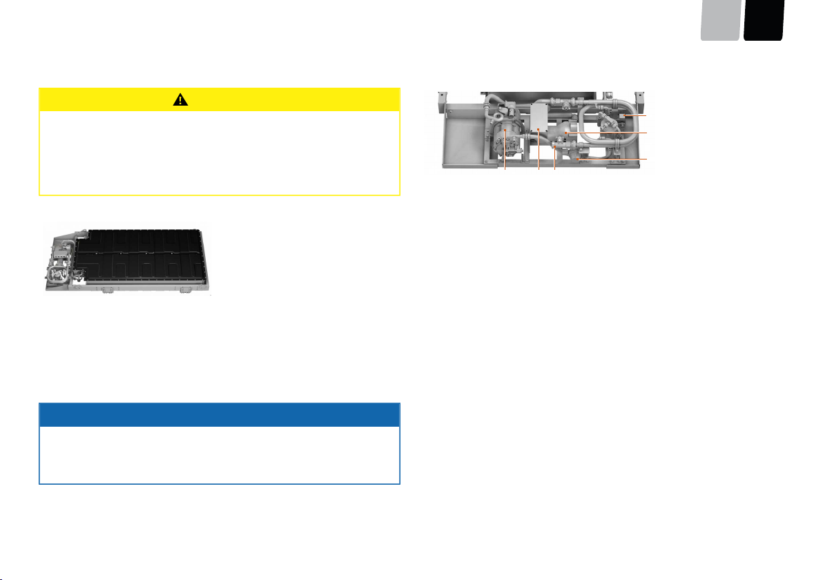
■The DEEP BLUE System has a venting opening on the casing in the unlikely
event that a cell degases. Always keep the hose outlet of the venting system
clear.
DANGER!
Danger of fire and burns from overheating or from hot surfaces on the
components.
Fire and hot surfaces can result in death or severe physical injuries.
■Do not store flammable objects in the area of the high-voltage equipment.
■Use only charging cables which are suitable for outdoor use.
■Always unroll the cables completely.
■If the DEEP BLUE system becomes very hot or you see steam or smoke,
switch the system off immediately.
■During or immediately after a trip, do not touch any of the motor or battery
components.
■Prevent strong mechanical forces from working on the batteries and cables
of the DEEP BLUE system.
DANGER!
Danger to life if the Emergency Stop is not triggered.
Death or severe physical injuries may result.
■Always attach the lanyard to the skipper's wrist or his life jacket.
WARNING!
Mechanical hazard from rotating components.
This can result in severe physical injuries or death.
■Do not wear jewellery or loose clothing in the vicinity of the drive shaft or
the propeller. Tie up long, loose hair.
■Switch off the DEEP BLUE system when there are people in the immediate
vicinity of the drive shaft or the propeller.
■Do not carry out maintenance or cleaning work on the drive shaft or pro-
peller if the DEEP BLUE system is engaged.
■Operate the propeller only when it is under water.
Safety
ENDE
page 18 / 117
WARNING!
Danger to life from a boat which is not manoeuvrable!
This can result in severe physical injuries or death.
■Before starting a trip, inform yourself of the intended travel area, and take
note of the predicted weather and water conditions.
■Depending on the size of the boat, keep the typical safety equipment ready
(anchor, paddles, means of communication, auxiliary drive if necessary).
■Check the system for mechanical damage before setting out on a trip.
■Do not use the system unless it is in proper working order.
WARNING!
Danger to life from overestimating the remaining range.
This can result in severe physical injuries or death.
■Before starting a trip, make yourself familiar with the travel area, because the
range displayed on the on-board computer does not take wind, current, and
direction of travel into account.
■Build in a sufficient buffer for the necessary range.
WARNING!
Danger of injury from propeller!
Moderate or severe physical injuries may result.
■When working on the propeller, always switch the system off at the main
switch.
■Pull off the lanyard.
WARNING!
Danger of cutting by the propeller.
Moderate or severe physical injuries may result.
■Keep away from the propeller.
■Comply with the safety provisions.
■Beware of people in the water.
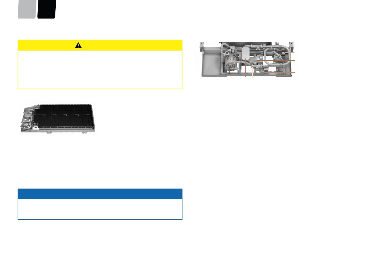
CAUTION!
Damage to the high-voltage battery from stepping on or placing objects on
it!
This can result in malfunctioning or material damage.
■Never step on the high-voltage battery.
■Never use the high-voltage battery as a support surface or lean on it.
■Do not place any objects on the high-voltage battery.
Commissioning/decommissioningDEEN
page 19 / 117
5Commissioning/decommissioning
Torqeedo Service or an authorised Service Partner carries out the commissioning
and decommissioning of the DEEP BLUE system.
Operation
ENDE
page 20 / 117
6Operation
WARNING!
Danger to life from a boat which is not manoeuvrable!
This can result in severe physical injuries or death.
■Before starting a trip, inform yourself of the intended travel area, and take
note of the predicted weather and water conditions.
■Depending on the size of the boat, keep the typical safety equipment ready
(anchor, paddles, means of communication, auxiliary drive if necessary).
■Check the system for mechanical damage before setting out on a trip.
■Do not use the system unless it is in proper working order.
6.1System start
In order to start the DEEP BLUE system, the remote throttle lever must be brought
into the neutral position. If the Emergency Stop Switch was previously triggered,
then it must again be placed in the initial position.
The system starts after the key switch has been turned. The remote throttle
lever beeps once and the Select LED (6) lights up. With a double remote throt-
tle lever, Select LEDs (4) and (6) light up in red, see "Fig. 36: Display overview",
page 35. The colour changes to orange within five seconds.
The drive is available, and runs in emergency mode (see Chapter 6.3.1, "Emergency
mode"), until the further system functions are ready and the colour of the Select LED
(6) changes to green. With a double remote throttle lever, the Select LEDs (6) and (4)
light up in green. This should not take longer than 20 to 30 seconds.
If the Select LEDs continue to flash red, an error has occurred. It may be possible to
correct this error by restarting the system.
OperationDEEN
page 21 / 117
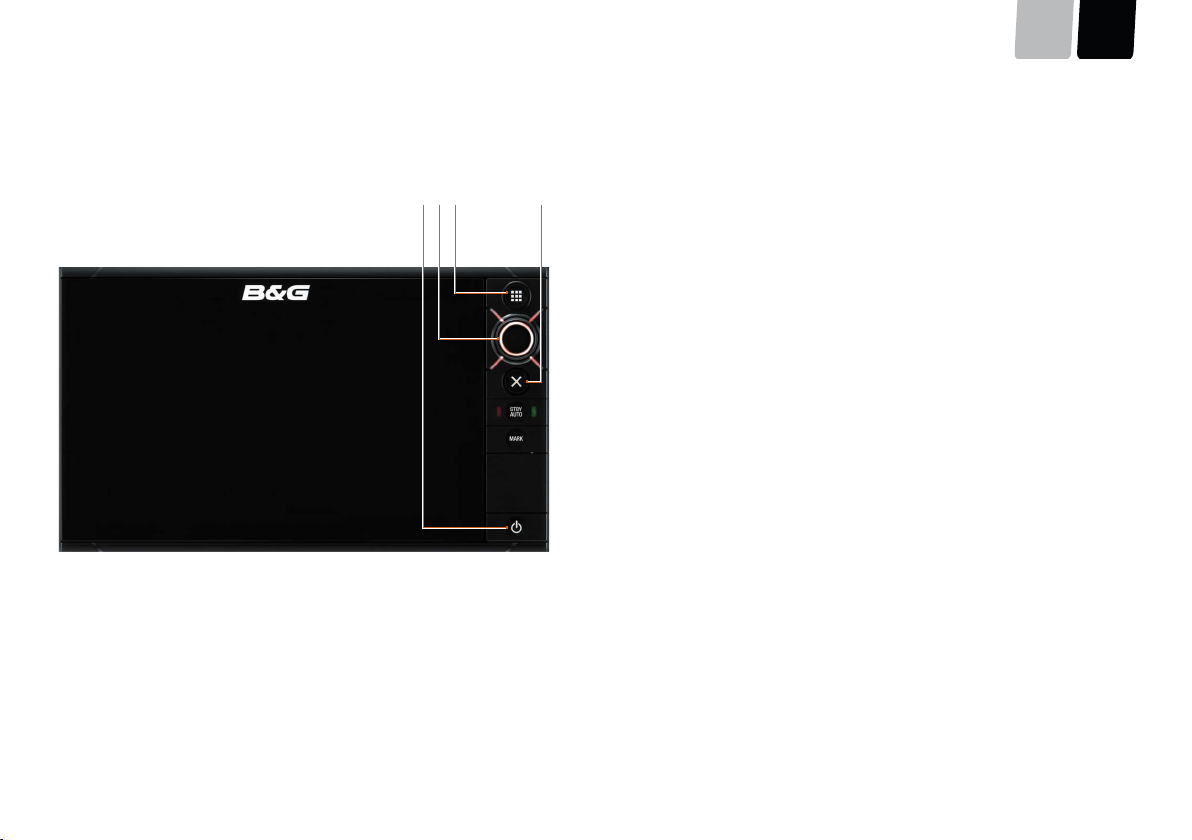
6.2System display
The system display features a convenient and safe option for controlling the DEEP BLUE system, and for monitoring each individual component. The system display is a touch-
screen.
3421
Fig. 20:System display
1Access standby and brightness setting
2Control for selecting the screens
3Access main menu
4Close the pop-up window
The brightness of the background illumination can be adjusted manually between four levels. To change between brightness levels, press button 1 several times.
Operation
ENDE
page 22 / 117
6.2.1Use of the touchscreen display
ADVICE
The touchscreen display can be operated using your fingers, special gloves, or a
touchscreen stylus. Before a trip, ensure that the touchscreen can be operated
correctly.
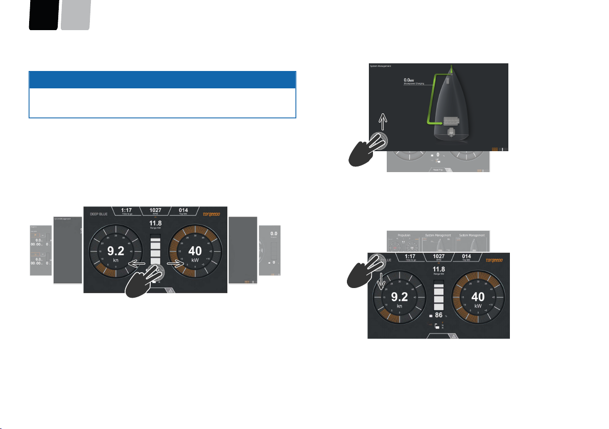
For operating the touchscreen display, the following options are available:
■Select screens, buttons, or control elements by touching them
■Navigate between screens by swiping with two fingers or by turning the rotary
knob
Swiping to left or right
Navigate between screens by swiping to the left or right with two fingers.
Fig. 21:Changing between screens
Swiping upwards
Change directly to the Drive screen by swiping upwards with two fingers. This is pos-
sible from any screen.
Fig. 22:Changing to the Drive screen
Swiping downwards
Change directly to the Main menu by swiping downwards with two fingers. This is
possible from any screen.
Fig. 23:Changing to the Main menu
OperationDEEN
page 23 / 117
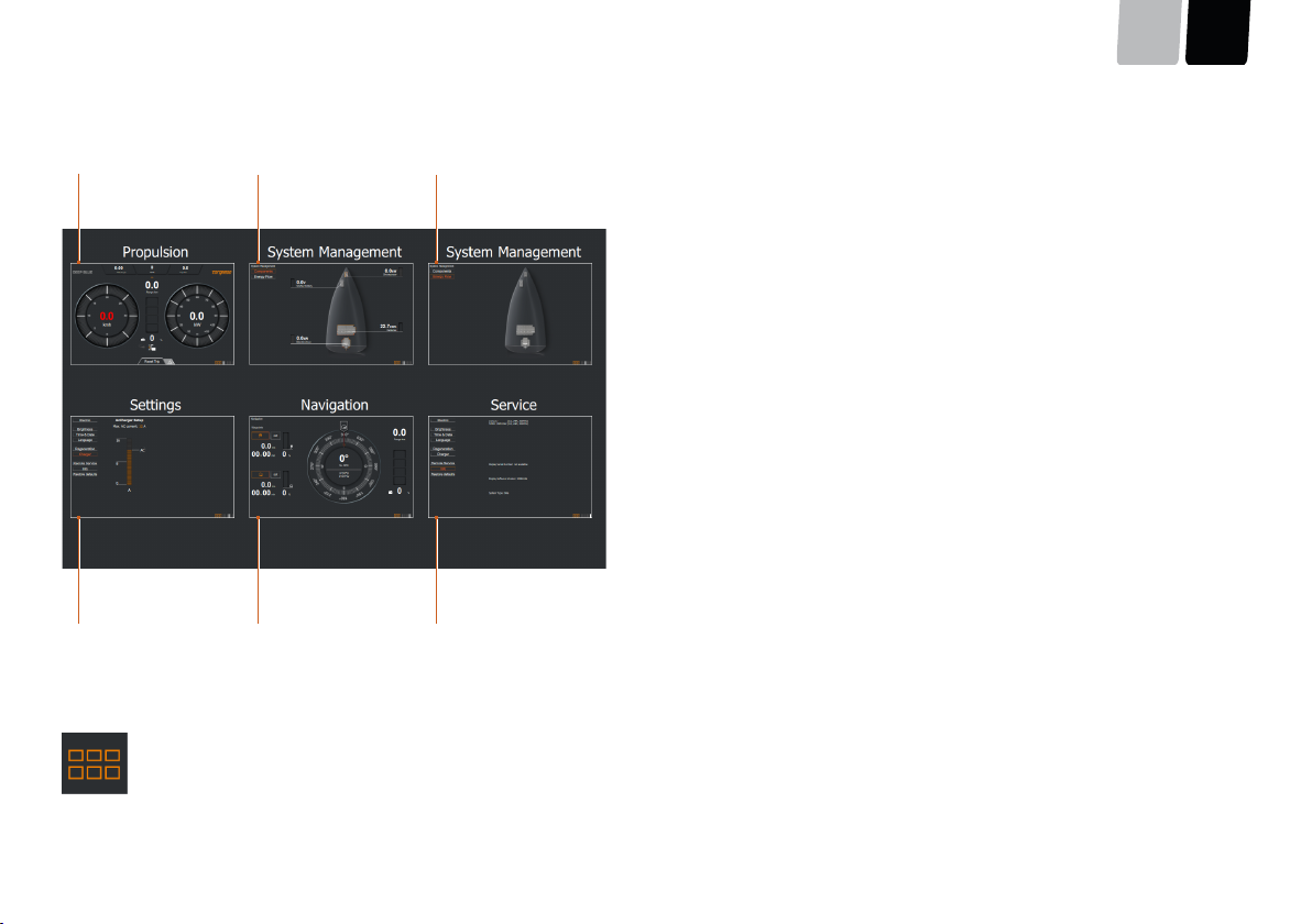
6.2.2Main menu
6
2
1
3
54
Fig. 24:Main menu
1Drive screen
2Information about individual components
3Energy flow
4Service
5Navigation
6Settings
If no screen is selected, then after eight seconds the screen changes automatically to the Drive screen. To return to the Main menu, touch the Main Menu button at the bottom
right of the screen.
Fig. 25:Main Menu button
Operation
ENDE
page 24 / 117
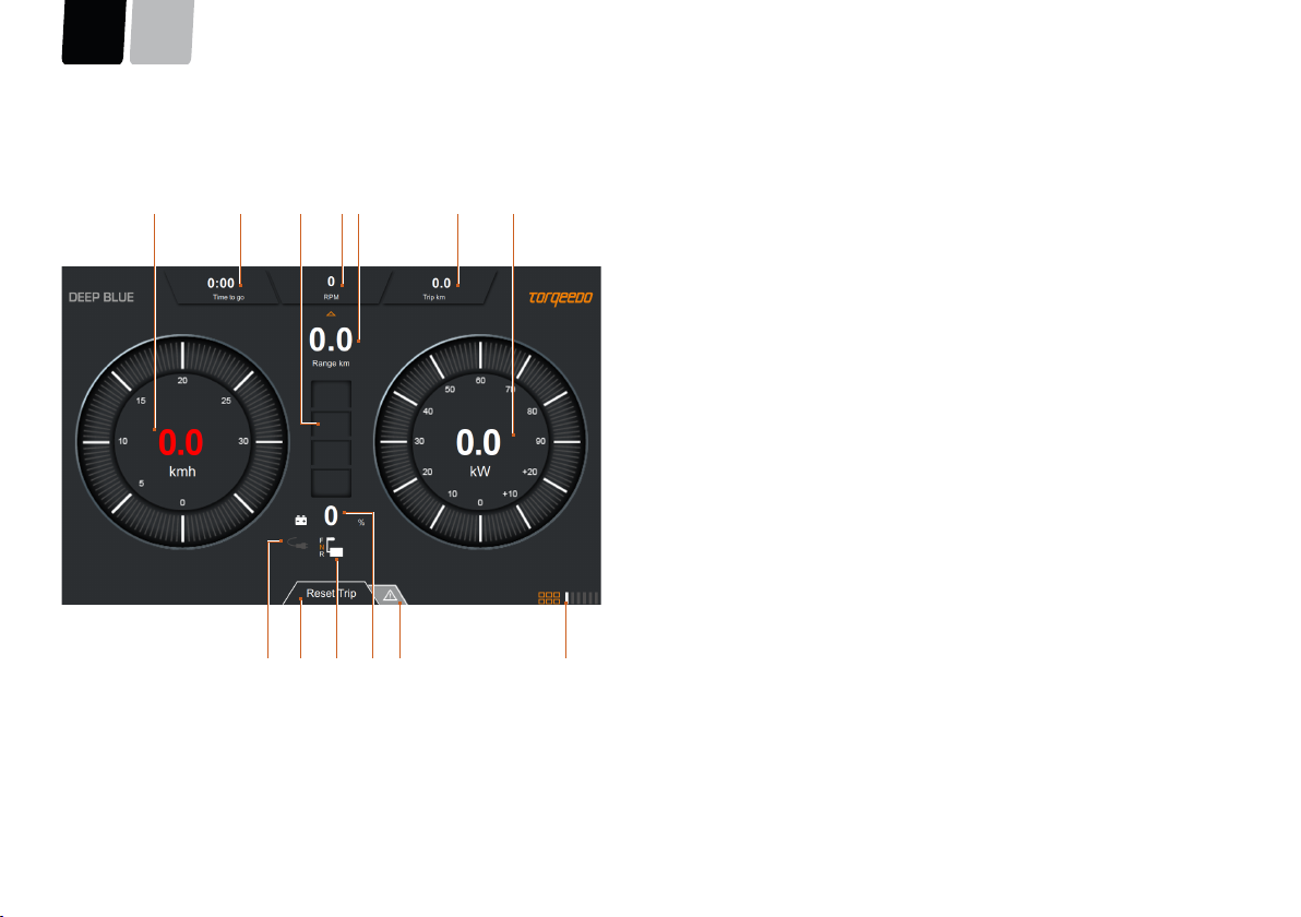
6.2.3Drive
All information required for normal travel mode is presented in a straightforward manner on the Drive screen.
9101112
138
2314567
Fig. 26:Drive screen
1Speed over ground (shown in red if there is no valid GPS position)
2Remaining run time
(if a GPS signal is available, the remaining range at the current speed is dis-
played)
3State of charge of high-voltage batteries
4Rotational speed of shaft
5Remaining range
6Trip distance
7Power consumption
8Displays the current menu - return to main menu
9Select error messages display
10State of charge of high-voltage batteries
11Remote throttle status display: forward/neutral/reverse
12Reset distance travelled
13Shore power charging active
OperationDEEN
page 25 / 117
Info area
The Info area in the top part of the Drive menu contains current information on the
remaining run time, rotational speed, and distance measurement.
Open the Info area by touching it or swiping downwards. Close the Info area by
swiping upwards.
The values are displayed as a combined result.
Fig. 27:Info area – open
Fig. 28:Info area – closed
Operation
ENDE
page 26 / 117
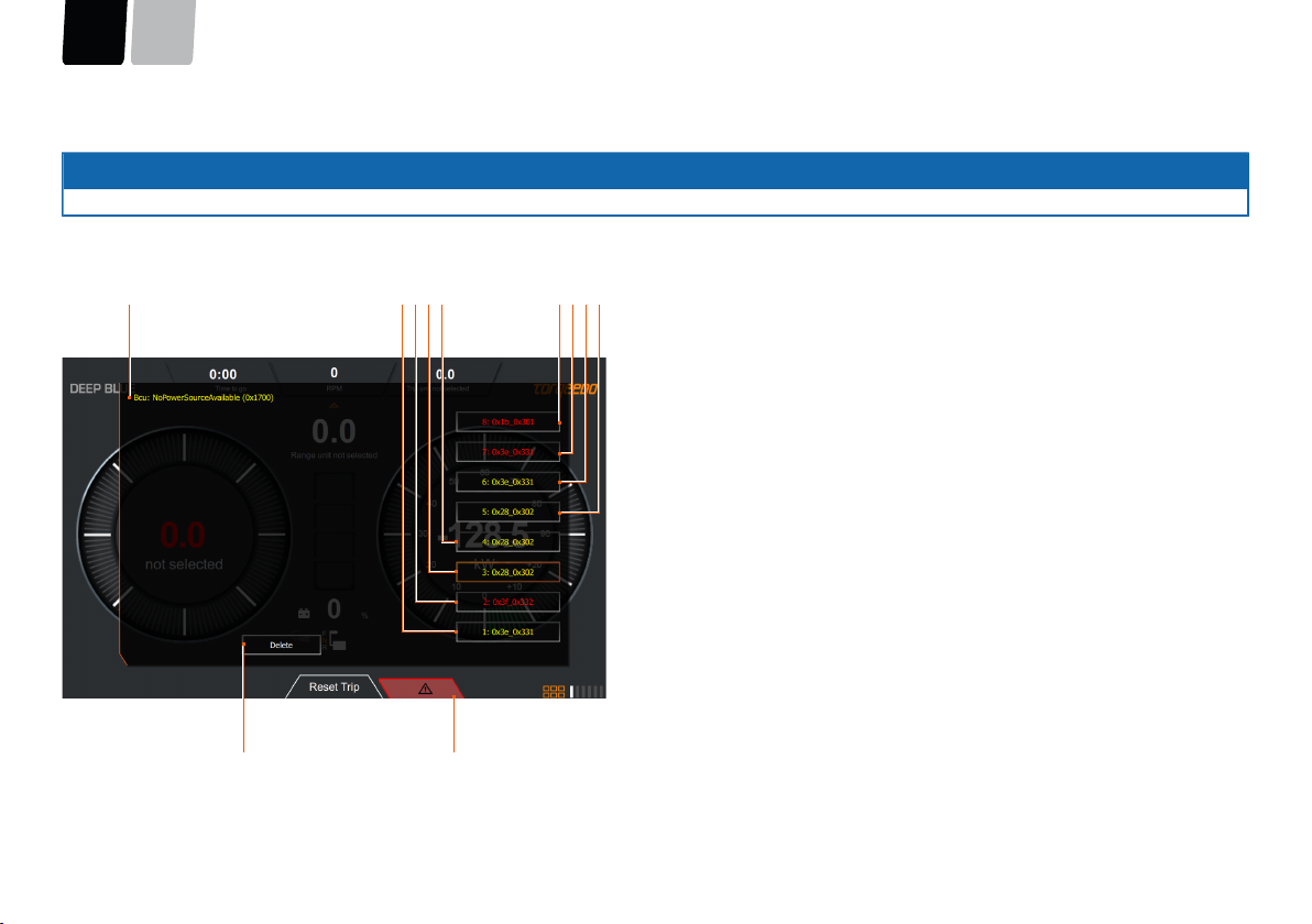
Error messages and warnings
ADVICE
Error messages and warnings are visible only on the Drive screen.
Depending on the current software version, warnings and error messages are displayed as an error code or as plain text. Torqeedo makes every effort to increase the conve-
nience with each update. In the event of uncertainty, please contact Torqeedo Service.
1011
5
1
432
9876
Fig. 29:Warnings and error messages
1Detailed description of error
2-9List of errors: The detailed description of the error is displayed by pressing the
appropriate button.
10The error display is minimised, and can be displayed again by pressing the
button once more.
11The currently displayed error is deleted from the list of errors.
As soon as error messages are listed, the error display button turns red, and be-
comes larger. Touch the button in order to open an Info window with the error
list. In the case of warnings, the Info window opens automatically.
Touch a message in the list to display the detailed error description.
The most recent errors are always displayed at the top of the list.
The colour of the error message indicates its danger level:
Yellow:Error
Red:Warning
OperationDEEN
page 27 / 117
6.2.4Component selection
The Component Selection screen displays the operating parameters of all system components. This screen may vary depending on the components installed. The following
image is an example.
2143
Fig. 30:Component selection
1Present motor power
2Starter battery voltage
3Present output of AC charger units
4Present energy content of the high-voltage batteries
Operation
ENDE
page 28 / 117
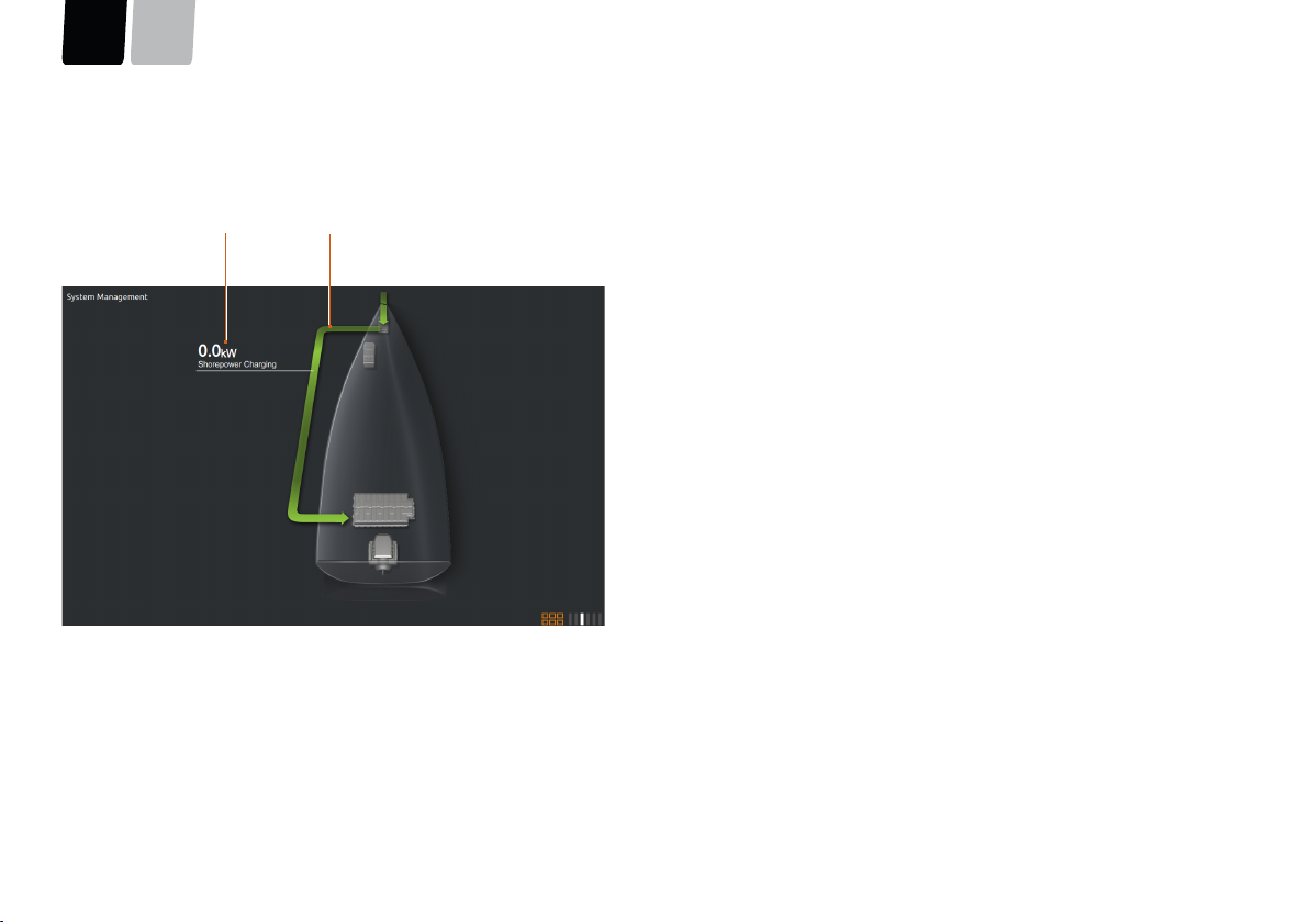
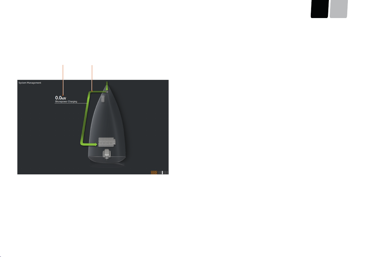
6.2.5Energy flow
The visual presentation of the energy flows between the system components makes it possible to obtain a rapid overview of the system’s operation. Green arrows mean that
energy is being supplied to the system. Orange arrows mean that energy is being consumed.
2
1
Fig. 31:Energy flow
1Power value: current power being transferred
2Direction of flow
Green: Energy is being input
Orange: Energy is being consumed
OperationDEEN
page 29 / 117
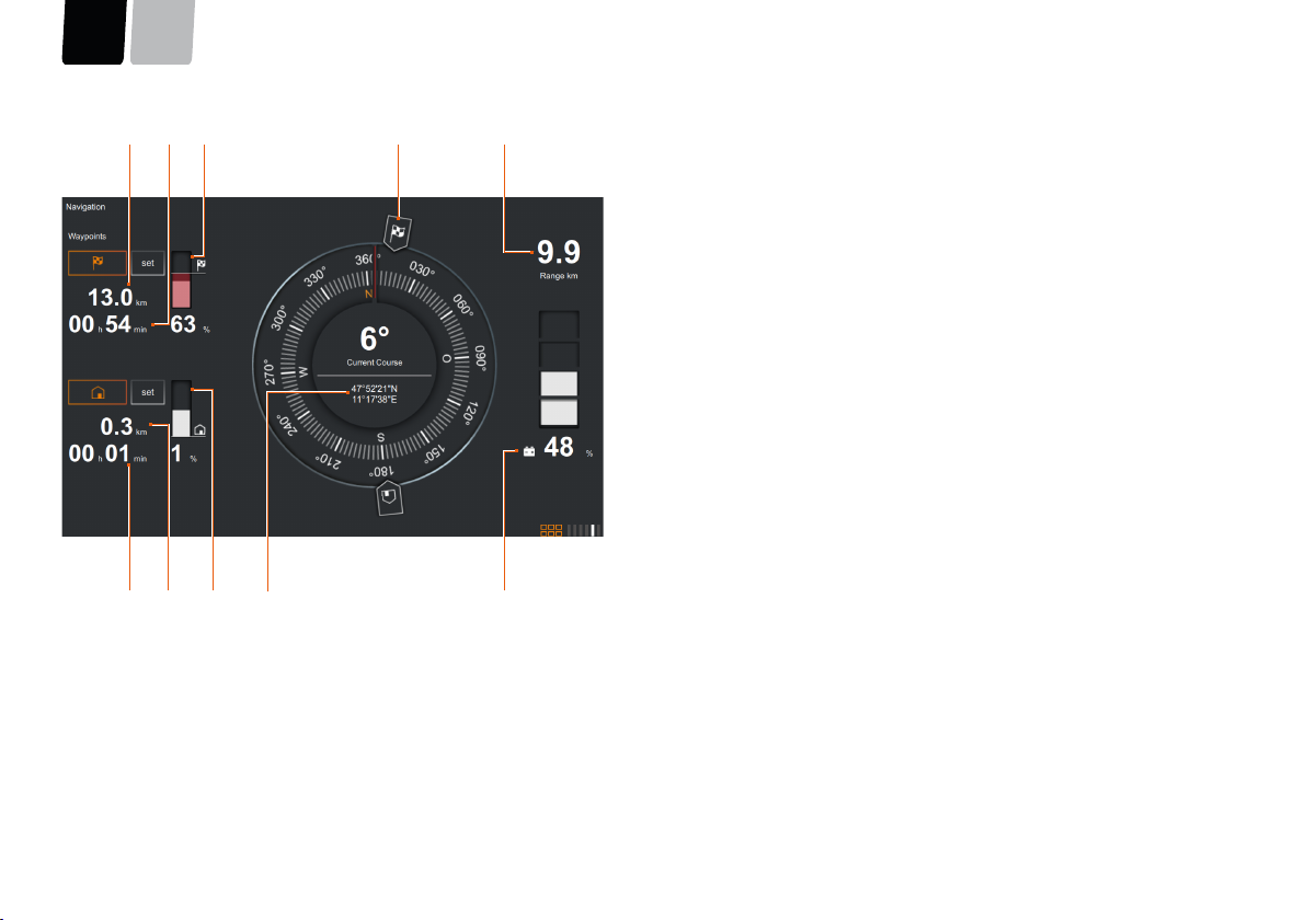
6.2.6Navigation
WARNING!
Danger to life from overestimating the remaining range.
This can result in severe physical injuries or death.
■Before starting a trip, make yourself familiar with the travel area, because the range displayed on the on-board computer does not take wind, current, and direction of
travel into account.
■Build in a sufficient buffer for the necessary range.
Operation
ENDE
page 30 / 117
45
1
2
9
1068
3
7
Fig. 32:Navigation
This function provides assistance for simple navigation in familiar waters.
1Distance from destination
2Travel time to destination at present speed
3SOC display: Estimated energy requirement to destination
4Compass with display of direction to start and destination
5Remaining range
6State of charge
7Current coordinates
8SOC display: Estimated energy requirement to return to start
9Distance from start
10Travel time to start at present speed
OperationDEEN
page 31 / 117
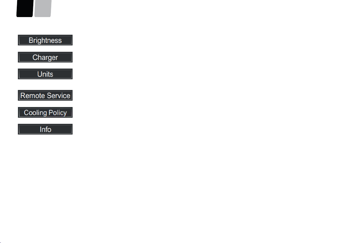
6.2.7Settings
The Settings screen can be used to configure system functions, such as display modes or operating parameters.
4
6
1
3
5
2
Fig. 33:Settings
1Selection of Cooling Policy
2Selection of brightness
3Select units of measure
4Select charger unit
5Select Remote Service
6Select information
Operation
ENDE
page 32 / 117
The Brightness tab can be used to manually adjust the basic brightness of the background illumination.
The Charger tab can be used to restrict the maximum output of each charger unit installed.
The Units tab can be used to set whether the speed, range, and distance travelled are displayed in metric, nautical, or Imperial
units of measure.
For liquids, the unit can be set for either litres or gallons.
The Remote Service tab can switch Remote Service on and off, carry out connection tests, and display the connection status. You
will find further information in Remote Service.
The Cooling Policy tab is used to set the temperature level from which the cooling water pumps start automatically.
For internal purposes - Torqeedo Service.
OperationDEEN
page 33 / 117
Remote Service
To commission the Remote Service maintenance function, contact Torqeedo Service. A prerequisite for use is for the user to establish an internet connection. If no individual
WLAN connection was configured during installation, then an optionally installed WLAN router searches for a WLAN whose SSID is "tqr" and password is "geheim1A". In order
to establish an Internet connection, a smartphone, for example, can be used to create a hotspot which uses the abovementioned data. Please contact Torqeedo service regard-
ing alternative GSM router solutions.
231456
Fig. 34:Remote Service available
231456
Fig. 35:Remote Service not available
1Connection status of router4Connection status of Torqeedo server
2Activate/deactivate Remote Service button5Connection status of Internet
3Button for executing connection test6Status of VPN connection of Torqeedo server
Operation
ENDE
page 34 / 117
Activate/deactivate Remote Service
Enabled:Remote Service is switched on
Disabled:Remote Service is switched off
Connection status of router
Green:Connection to the router installed on the boat can be established
Red:Router switched off or defective, network cable or system controller
defective
Connection status of Internet
Green:Connection to Internet has been established
Red:Internet connection not available, or test server does not respond
Connection status of Torqeedo server
Green:Connection to the Torqeedo server has been established
Red:Internet connection not available, or Torqeedo server does not re-
spond
Status of VPN connection of Torqeedo server
Available:VPN connection to the Torqeedo server has been established
Not Available:Internet connection not available, Torqeedo server does not re-
spond, or router is not configured correctly
ADVICE
The green/red buttons display the status of the respective request. In order to
ensure that the connection is permanently established, the request must be re-
peated. In order to reduce the use of data volumes, Torqeedo does not use an
automatically permanent request.
Perform connection test
The output status of the connection test is update.
In order to perform the connection test to the Remote Service, press the Perform
connection test button.
While the connection test is being performed, the status remains at pending.
As soon as the connection test is complete, the status changes back to update.
The results of the connection test are displayed below (3-6).
OperationDEEN
page 35 / 117
6.3Remote throttle display
7
8
109
3
2
1
456
Fig. 36:Display overview
1Brightness sensor6Select LED for starboard
2Browse backwards7Confirm selection
3Browse forwards8Back
4Select LED for port
(only for double throttle lever)
9Neutral LED for starboard
5Display10Neutral LED for port
(only for double throttle lever)
The remote throttle display is used only for the calibration of the remote throttle. All
other settings can also be performed via the system display. The remote throttle dis-
play is operated by pressing the relevant buttons next to the display.
In addition, the remote throttle display is used for ensuring operational readiness
during emergency operation and/or if the touchscreen display fails. If the system
is connected to the shore-based power supply while switched off, then the charge
state is displayed here.
Select LED
If multiple stations on the boat are being operated, the Select LED displays whether
the remote throttle is active.
Green:The remote throttle is active.
Flashing green:The remote throttle is currently being activated.
Off:The remote throttle is inactive.
Orange:Emergency travel mode
Flashing red:System error
Neutral LED
The Neutral LED indicates whether the remote throttle is in the neutral position.
Green:The remote throttle is active and in the neutral position.
Off:The motor is in operation or the remote throttle is inactive.
Operation
ENDE
page 36 / 117
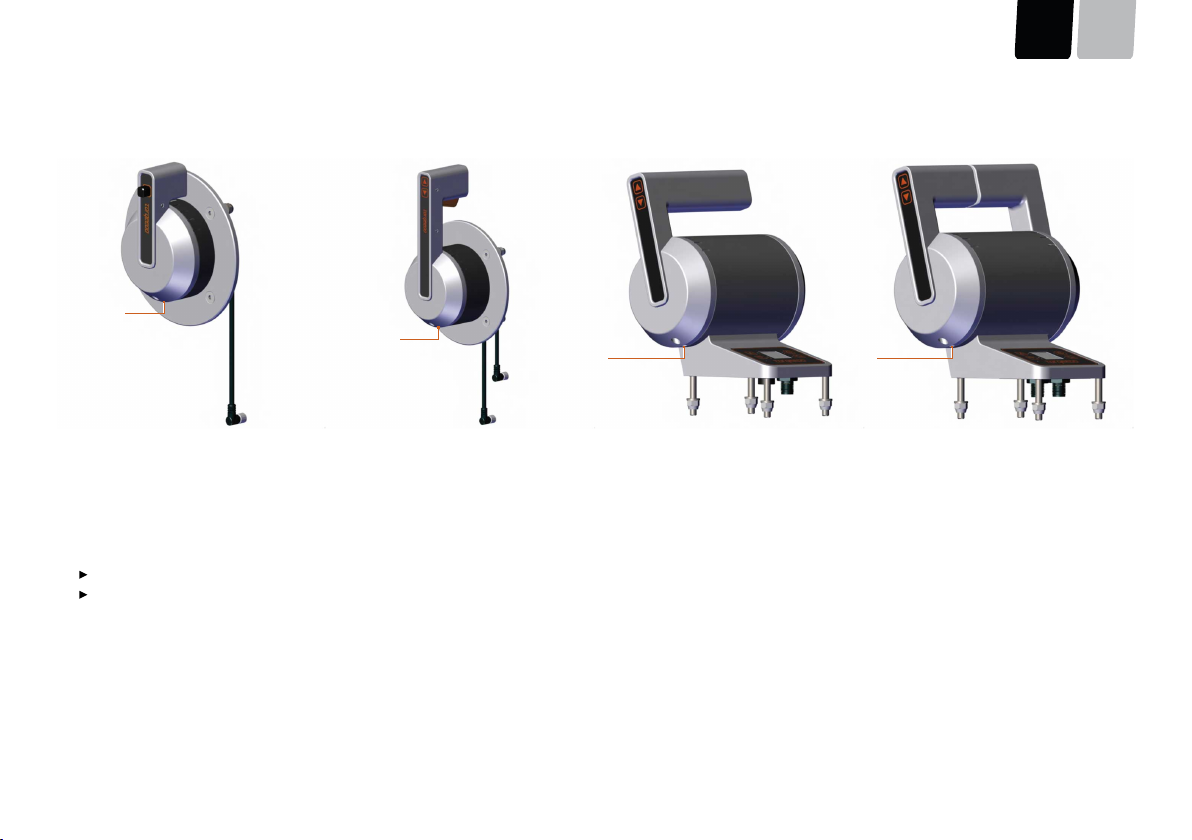
Calibration
ADVICE
If the Sail remote throttle with side mounting or the remote throttle with side
mounting is installed other than as intended (see label on the remote throttle),
then this must be recalibrated manually.
Fig. 37:Calibration display view
As standard, the Sail remote throttle with
side mounting and the remote throt-
tle with side mounting are calibrated
for right-hand installation. If the remote
throttle is mounted on the other side of
the boat, then it must be recalibrated ac-
cordingly.
The Calibration menu is accessed by
pressing and holding the Confirm selec-
tion button.
Maximum forward position
Fig. 38:Display maximum forward position
1.Move the lever, or both levers in the
case of the double remote throttle
with top mounting, to the maximum
forward position.
2.Press the Confirm selection button.
Maximum reverse position
Fig. 39:Display maximum reverse position
1.Move the lever, or both levers in the
case of the double remote throttle
with top mounting, to the maximum
reverse position.
2.Press the Confirm selection button.
Neutral position
Fig. 40:Display the neutral position
1.Move the lever, or both levers in the
case of the double remote throttle
with top mounting, to the neutral po-
sition.
2.Press the Confirm selection button.
6.3.1Emergency mode
To ensure maximum operational reliability, the DEEP BLUE system has redundant
functional levels, so that it can react to malfunctioning. This means, for example, that
the electronic position sensors in the throttle lever are double.
If significant system components such as the main screen fail, then the system
changes to emergency mode. This is indicated by the Select LED (6) on the remote
throttle lever lighting up in orange. With a double remote throttle lever, the Select
LEDs (6) and (4) light up in orange.
In emergency mode, the main drive has top priority, and is the only function to be
supported. With twin systems, the connection between the two drive trains can be
disconnected automatically if this is of benefit for current operational reliability.
OperationDEEN
page 37 / 117
In emergency mode, the system status of the drive is monitored by means of the
coloured LEDs on the remote throttle lever. It is not possible to charge the system in
this mode until the causes of the technical problems have been remedied.
6.4Emergency Stop
DANGER!
Danger to life if the Emergency Stop is not triggered.
Death or severe physical injuries may result.
■Always attach the lanyard to the skipper's wrist or his life jacket.
There are various options for stopping the system rapidly:
Sail accelerator lever with side mounting
■Place the remote accelerator lever in the neutral position.
■Press the Emergency Off Switch.
An Emergency Off Switch which has been pushed down can be returned to
its original position by pulling it out.
■Move the On/Off switch to the Off position.
Throttle lever with side mounting
■Place the remote accelerator lever in the neutral position.
■Move the key switch to the Off or 0 position.
■Actuate the kill switch by pulling the lanyard.
Single Top Mount Throttle
■Place the remote accelerator lever in the neutral position.
■Press the Emergency Off switch.
An Emergency Off Switch which has been pushed down can be returned to
its original position by pulling it out.
■Move the key switch to the Off or 0 position.
Double accelerator lever with top mounting
■Place the remote accelerator lever in the neutral position.
■Press the Emergency Off Switch.
An Emergency Off Switch which has been pushed down can be returned to
its original position by pulling it out.
■Move the key switch to the Off or 0 position.
ADVICE
■Test the functioning of the Emergency Stop at low motor power (< 2 kW) be-
fore every trip.
■In emergency situations, actuate the Emergency Stop immediately.
■At high power, use the Emergency Stop only in emergency situations.
Repeated actuation of the Emergency Stop at high power stresses the
DEEP BLUE system, and can cause damage to the electronics.
Operation
ENDE
page 38 / 117
6.5Travel mode
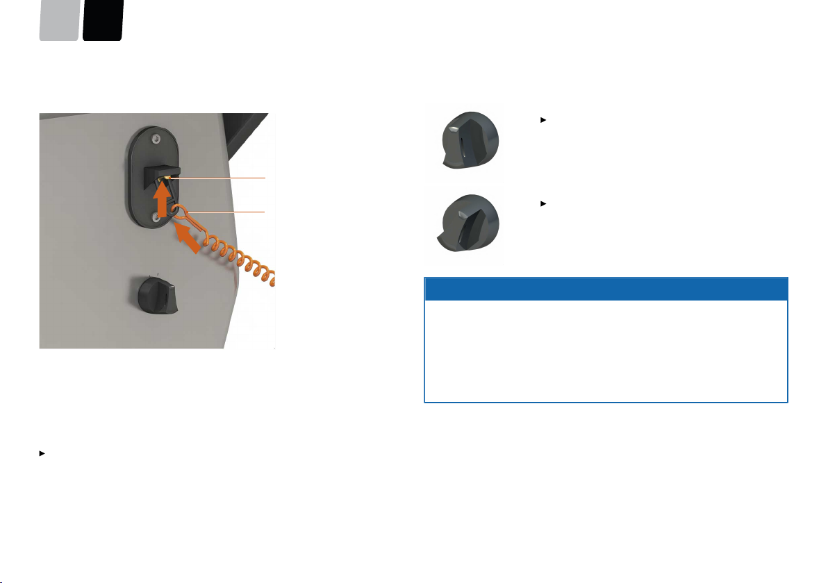
Securing the Emergency Stop Switch throttle lever with side mounting
2
1
12
Fig. 41:Emergency Stop Switch
1Lanyard2Emergency Stop Switch
1.Lay the pilot-line (1) via the Emergency Stop Switch (2).
2.Place the Emergency Stop Switch (2) in the RUN position.
You can now start the system using the key switch.
Position of the key switch for the throttle lever with side mounting, top
mounting, and double throttle lever with top mounting
Key in position 1
System is switched off.
Key in position 2
System is switched on and ready to start.
The key cannot be pulled out in this position.
ADVICE
■If there is visible damage to components or cables, do not turn on the
DEEP BLUE system.
■Ensure that all people on board wear a life jacket.
■Before starting, attach the pilot-line of the Emergency Stop to your wrist or
life jacket.
■The charge state of the battery must be checked at intervals while on the
move.
OperationDEEN
page 39 / 117
6.5.1Starting a trip
ADVICE
During breaks in a trip, if there are swimmers near the boat:
Ensure that the system is switched off, in order to prevent unintentional opera-
tion of the remote throttle.
ADVICE
■If there is visible damage to components or cables, do not turn on the
DEEP BLUE system.
■Ensure that all people on board wear a life jacket.
■Before starting, attach the pilot-line of the Emergency Stop to your wrist or
life jacket.
■The charge state of the battery must be checked at intervals while on the
move.
Starting motor using the throttle lever with side mounting, throttle lever with
top mounting, and double throttle lever with top mounting
Single Top Mount Throttle, Twin Top Mount Throttle
1.Ensure that the Emergency Off Switch is not depressed.
Throttle lever with side mounting:
2.Ensure that the Emergency Stop Switch has been secured, see Chapter 6.5,
"Travel mode".
3.Ensure that the remote throttle is in the neutral position.
4.Turn the key switch to position 2.
The display switches on.
The Select LED lights up green at the active station.
Starting motor using the Sail throttle lever with side mounting
ADVICE
The system can be started only if the Emergency Stop has not been actuated.
1.Ensure that the Emergency Off Switch is not depressed.
2.Ensure that the remote throttle is in the neutral position.
3.Press the On/Off switch to start the system.
The On/Off switch engages.
The display switches on.
The Select LED lights up green at the active station.
Operation
ENDE
page 40 / 117
6.5.2Motion forward/reverse
2
3
55°
55°
1
Fig. 42:Operating the remote throttle during
forwards/backwards motion
2
3
55°
55°
1
Fig. 43:Operating the remote throttle during
forwards/backwards motion
1
2
55°
55°
Fig. 44:Operating the remote throttle during
forwards/backwards motion
1
2
55°
55°
Fig. 45:Operating the remote throttle during
forwards/backwards motion
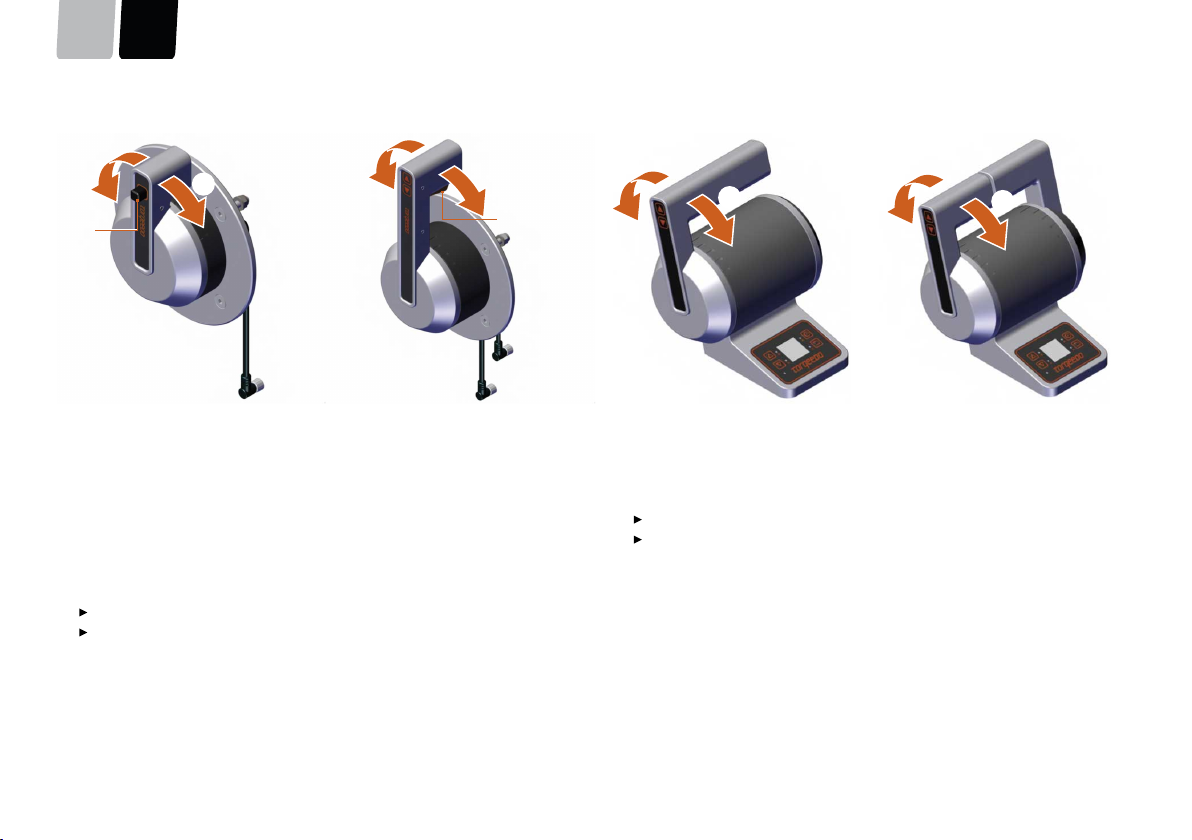
The remote throttle can be swivelled a maximum of 55° forwards and 55° backwards.
Side Mount Throttle Sail, Side Mount Throttle
1.For forwards or backwards motion, release the lock (1) on the neutral position.
2.Operate the remote throttle accordingly.
Forward (2)
Reverse (3)
Verwenden Sie für das Trimmen und Kippen des Außenborders während der Fahrt
die zwei Pfeiltasten (4) auf dem Ferngashebel.
Single Throttle Top Mount, Twin Throttle Top Mount
1.Operate the remote throttle accordingly.
Forward (1)
Reverse (2)
Verwenden Sie für das Trimmen und Kippen des Außenborders während der Fahrt
die zwei Pfeiltasten (3) auf dem Ferngashebel.
OperationDEEN
page 41 / 117
6.5.3End trip
Sail accelerator lever with side mounting
Move the lever back to the neutral position and press the On/Off switch in order to
switch off the complete system.
Throttle lever with side mounting and throttle lever with top mounting
Move the lever back to the neutral position and turn the key fully to the left in order
to switch off the complete system.
Double accelerator lever with top mounting
Move both levers back to the neutral position and turn the key fully to the left in or-
der to switch off the complete system.
ADVICE
During breaks in a trip, if there are swimmers near the boat:
Ensure that the system is switched off, in order to prevent unintentional opera-
tion of the remote throttle.
ADVICE
At the end of a trip, follow the instructions in Chapter 8.4, "Storage".
6.6Charging the high-voltage batteries
DANGER!
Danger of fire and burns from overheating or from hot surfaces on the
components.
Fire and hot surfaces can result in death or severe physical injuries.
■Do not store flammable objects in the area of the high-voltage equipment.
■Use only charging cables which are suitable for outdoor use.
■Always unroll the cables completely.
■If the DEEP BLUE system becomes very hot or you see steam or smoke,
switch the system off immediately.
■During or immediately after a trip, do not touch any of the motor or battery
components.
■Prevent strong mechanical forces from working on the batteries and cables
of the DEEP BLUE system.
Prerequisites:
■The fuse for the Emergency Stop Switch must not be removed.
■The Emergency Off Switch must not be depressed.
1.To start the charging process, insert the charger plug into the provided socket
ashore.
The charging process starts automatically.
If the system is switched on, then the displays switch on automatically. If the
system is switched off, only the display for the accelerator lever is switched
on.
As soon as AC voltage is detected at the plug, an icon is displayed on the
Drive screen.
An arrow and the combined charging power of all charger units are displayed
on the Energy Flow screen.
A plug symbol and the charging power are displayed on the accelerator lever
display.
Operation
ENDE
page 42 / 117
2.To end the charging process, pull the charger plug out of the socket.
ADVICE
Although the high-voltage batteries of the DEEP BLUE system are protected
from deep discharging, a certain self-discharge is unavoidable.
In order to prevent damage to the high-voltage batteries, comply with the fol-
lowing instructions:
■Top-up the charge of the high-voltage batteries after every trip. If the high-
voltage batteries are discharged to below 20 %, then they must be recharged
within 48 hours.
■During extended storage, check the state of charge of the
high-voltage batteries once per month, by reading the state of charge from
the main screen (see "Fig. 26: Drive screen", page 24). The value must be
greater than 20 %.
■Laden Sie die Hochvolt-Batterien nur bei den erlaubten Umgebungstemper-
If the sockets available for charging cannot provide the power required by the
charger unit, then under "Settings | Charger unit", the maximum current per charg-
er unit can be set using a slider, until problem-free charging is achieved.
This extends the charging time required.
If the high-voltage batteries or the charger unit heat up significantly during the
charging process (e.g. at very high ambient temperature), or they disrupt the supply
voltage excessively, then the charger unit reduces the charge automatically. This also
extends the charging time.
Via System Management | Components | Charger or Battery you can view de-
tailed values for the charging process.
The present state of charge can be monitored at any time on the Drive screen under
Time to full or via the small display.
Towing the boatDEEN
page 43 / 117
7Towing the boat
CAUTION!
Damage to drive components from ground contact when towing.
Material damage can result.
■While in motion, ensure that there is no danger of the propeller making con-
tact with the ground.
ADVICE
While the boat is ashore, set Cooling Policy to Late.
When towing the boat, the seacock and the outboard outlets should be closed.
Comply with the applicable national regulations for towing boats.
Care and service
ENDE
page 44 / 117
8Care and service
ADVICE
■If the batteries or other components show signs of mechanical damage, stop
using the DEEP BLUE system. Contact Torqeedo Service or an authorised ser-
vice partner.
■Ensure that the system components of the DEEP BLUE system are clean at all
times.
■Do not store foreign objects in the area of the high-voltage components.
ADVICE
Maintenance tasks must be carried out exclusively by qualified specialist person-
nel. Contact Torqeedo Service or an authorised Service Partner.
Before maintenance or cleaning tasks, ensure the following:
■The Emergency Stop Switch must be tripped.
■The key switch must be set to 0.
■On land, the charger plug must be disconnected.
8.1Care of the system components
The surfaces of the DEEP BLUE system can be cleaned with commercially available
cleaners; the plastic surfaces can be treated with vinyl cleaner.
Check the water strainer of the DEEP BLUE system before every trip, and clean if nec-
essary.
ADVICE
Have corrosion and paintwork damage corrected by a specialist if it occurs.
8.2Care of the high-voltage batteries
It is essential that the high-voltage batteries of the DEEP BLUE system must be pro-
tected from becoming deeply discharged. Because batteries are subject to self-dis-
charge, a damaging deep discharging is nevertheless possible; this can result in the
permanent destruction of the high-voltage batteries.
Therefore comply with the following instruction:
■Top-up the charge of the high-voltage batteries after every trip. Ideally, charg-
ing should take place immediately after use. If the high-voltage batteries are dis-
charged to below 20 %, then they must be recharged within 48 hours.
ADVICE
At the end of a trip, follow the instructions in Chapter 8.4, "Storage".
Care and serviceDEEN
page 45 / 117
8.3Maintenance intervals
If the prescribed maintenance intervals are not complied with or documented, the guarantee and warranty become void. Ensure that the services carried out are documented
in your service check folder.
Check by the customer before every use
ComponentActivity
Emergency Stop SwitchCheck functionality
Complete systemVisual inspection of all components
Cooling systemsCheck/clean filters
PumpsCheck flow
Connections/hosesCheck for leaks
Check attachmentVenting of high-voltage battery (op-
tional)Check draining openings
Check by the customer (O) or by Torqeedo technician (X)
Screws and bolts in the boxInternal visual inspection and check torque of
cable connections
X
AC Charger and Shore Power Distribution
(S/L)
Activity1000 h/annuallySpecial intervals
Internal visual inspectionX
Control ComponentsActivity1000 h/annuallySpecial intervals
Remote throttleCheck functionalityO
Visual inspectionO
Check functionalityO
Display
Check the remote connectionX
Emergency Stop SwitchCheck functionalityO
Cables in generalVisual inspection and checking attachmentO
Visual inspection and checking attachmentOGeneral plugs and connections
Electrical testO
*Whichever is earlier
8.3.1Replacement parts
ADVICE
For information on replacement parts and their installation, contact Torqeedo Service or an authorised Service Partner.
Care and service
ENDE
page 48 / 117
8.4Storage
CAUTION!
Danger of burns from hot surfaces or liquids.
Slight or moderate physical injuries may result.
■Use appropriate personal protective equipment.
■Do not touch the drive components or batteries of the DEEP BLUE system
immediately after use.
■Allow the DEEP BLUE system to cool down before working in the immediate
vicinity.
8.4.1Long-term storage and winterizing
ADVICE
Water/glycol mixture must not enter the environment, and must be disposed of
separately.
Water cooling
In order to prevent frost damage and corrosion, for long-term storage no sea water
may remain in the components or hoses of the cooling circuits.
The cooling water pump is activated if necessary via the system display, via Settings
| Cooling Policy, see Chapter 6.2.7, "Settings". Briefly set the parameter to Imme-
diate. This manually switches on all cooling pumps.
If there is no water in the system, restrict the running time to five minutes. If possi-
ble, disconnect unaffected pumps from the electrical supply.
Flushing and draining the coolant circuit
ADVICE
The following process must be carried out individually for each coolant circuit.
1.Close all cooling circuit water inlets.
2.Prepare approx. 10 to 20 litres of water/glycol mixture (mix ratio: 1:1) in a con-
tainer.
3.Loosen the cooling water intake inside the boat.
4.Activate the cooling water pump in order to pump remaining sea water out of
the system.
5.Position the collecting container under the cooling water outlet.
6.Pump the glycol mixture through the system via the cooling water supply line,
and collect it at the outlet.
ADVICE
The mixture collected can be used again for this type of flushing process in
other coolant circuits.
7.Allow the pump to run until no more liquid is discharged.
8.After the work is complete, use the system display to set Cooling Policy to Late,
see Chapter 6.2.7, "Settings" .
This prevents the pump from running dry too long and becoming damaged.
9.Open the filter for the sea water pumps.
10.Check the filter for damage, and clean it if necessary.
11.Re-insert the filter for the sea water pumps.
12.Close filter housing again.
Winterizing the electrical system
Comply with the permitted storage temperatures, see Chapter 3, "Technical data".
1.For storage in a warm environment, ensure good ventilation.
Care and serviceDEEN
page 49 / 117
ADVICE
If several high-voltage batteries are installed, check each battery individual-
ly on the system screen. At the start of the storage period, the charge state
must be between 30 % and 70 %.
2.Check the balancing state.
If the status is not Balanced, contact a certified Torqeedo dealer or Torqeedo
Service.
3.Disconnect the system from the AC power supply.
4.Disconnect the 12 V battery from the system.
5.Disconnect the battery terminals.
6.Always store lead and AGM batteries at temperatures above 0 °C.
Regular inspection (every 3 months)
1.For the inspection, connect the 12 V battery.
2.Switch the system on.
3.Check the high-voltage battery state of charge on the system screen.
If several batteries are installed, check each battery individually.
4.Recharge the high-voltage battery if the charge state is less than 20 %.
5.Check whether there are warnings or error messages in the system.
If there is a warning or error message, contact a certified Torqeedo dealer or
Torqeedo Service.
6.Check the balancing state.
If the status is not Balanced, contact a certified Torqeedo dealer or Torqeedo
Service.
7.Switch the system off.
8.Disconnect the 12 V battery from the system.
Recommissioning the electrical system
1.Connect the 12 V battery to the system.
2.Fully charge the high-voltage battery after every trip.
3.Ensure that all cooling water hoses are securely connected to the on-board in-
take valves.
4.Open the on-board intake valves.
5.For testing, set Cooling Policy to Immediate on the system display.
6.As soon as the boat is in the water, check the cooling water discharge at the on-
board outlets while the cooling pumps are running.
7.Flush the cooling water circuits with fresh water.
8.Check that pumps work properly and the systems are free from leaks.
9.Set Cooling Policy to Normal.
Care and service
ENDE
page 50 / 117
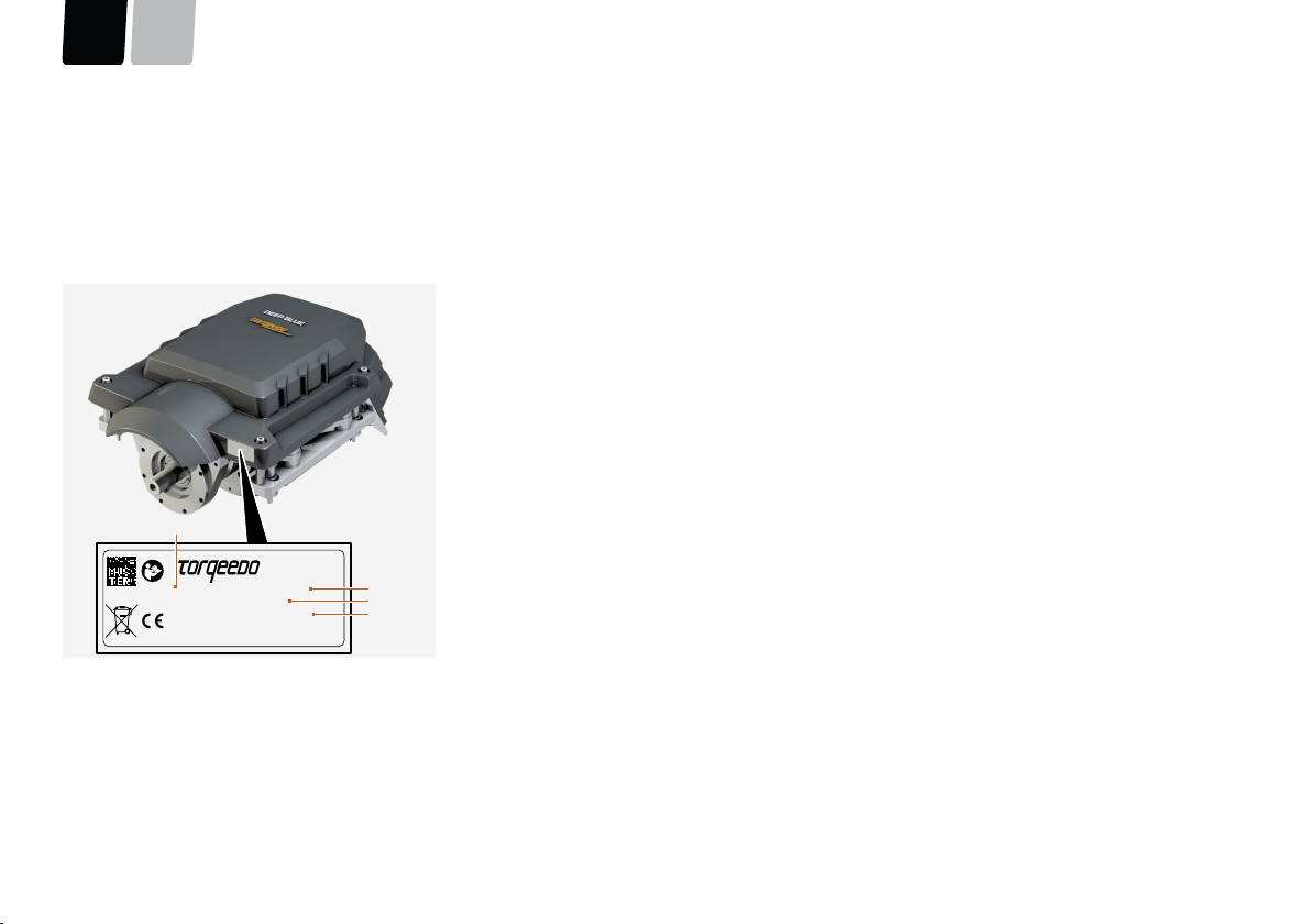
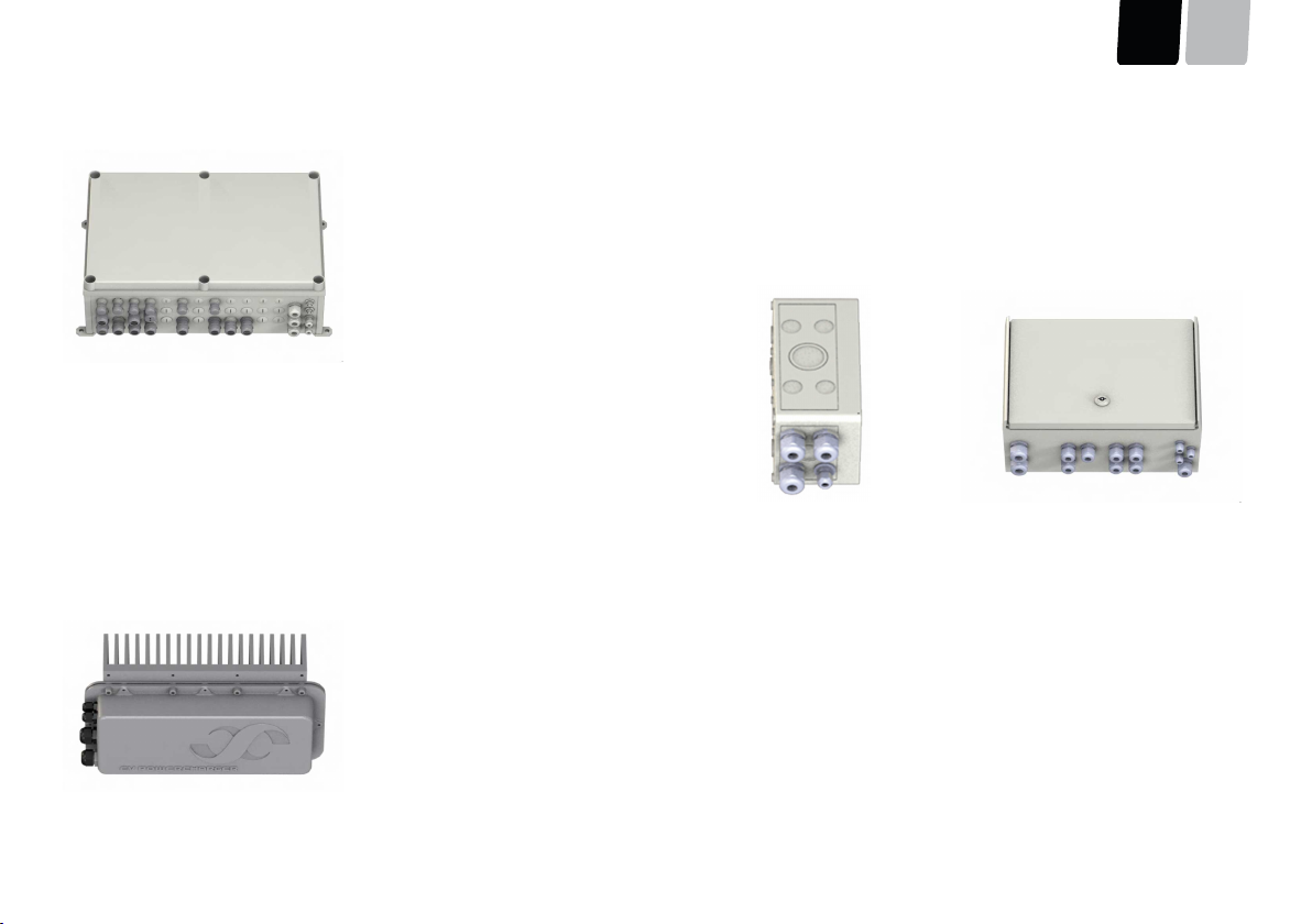
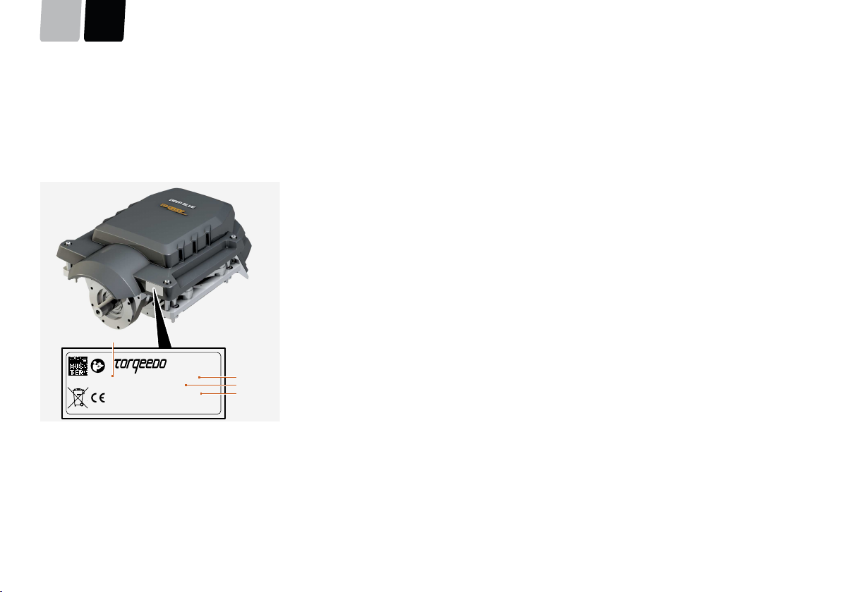
8.5Nameplate and serial number
Every DEEP BLUE system has an individual system serial number which is relevant for
guarantee purposes. At Torqeedo, all components of the systems are managed un-
der this number. This system serial number is applied to the side of the System Man-
agement Unit.
A stamped plate is fitted to each motor belonging to the DEEP BLUE system; it
records the key data as per the EC machinery directive 2006/42/EC.
000-00411 Deep Blue 80i 1800
S.Nr. 15509004A000004112
400V DC/50kW/1800rpm/80kg
Manufactured 2015 by Torqeedo GmbH
Friedrichshafener Str. 4a, D-82205 Gilching, Germany
2
3
4
1
Fig. 46:Nameplate
1Item number3Serial number
2Motor type4Operating voltage/power (continuous
output)
TroubleshootingDEEN
page 51 / 117
9Troubleshooting
ErrorCauseChecking/correction
Main switch is offCheck the boat's main switch, and switch it on if necessary.System display does not switch on after turning
the key switch or inserting the charger plug.1.Check the charge state of the 12 V battery. If the charge state
is low, switch off all loads not forming part of the electrical
drive system; charge using an external charger unit if neces-
sary. For reliable operation, the system requires a battery volt-
age of at least 11 V.
2.Check the boat's fuse for the 12 V battery, and replace the
fuse if defective.
During charging process with main screen
switched off, remote throttle display is not acti-
vated
Shore power connectionDuring the charging process: Check the shore-based plug con-
nections, cables, and fuses, and correct possible faults.
Charger unit is not activatedCheck on the main screen whether the charger unit is set to On.
Switch on if necessary.
Shore power connectionCheck whether the charging cable symbol is shown on the dis-
play. If not: check whether the fuse of the shore-based power
supply has tripped. If necessary, reconnect/replace the fuse and,
if required, reduce the charging power of the charger unit, as de-
scribed in Chapter 6.2.7, "Settings".
Battery does not charge
Cable lengthVoltage fall-off can arise if there are long cable runs between
socket and charger unit. This prevents the high-voltage batteries
from charging. If possible, try to charge using a shorter cable.
Troubleshooting
ENDE
page 52 / 117
ErrorCauseChecking/correction
Battery does not chargeStarter key and Emergency Stop SwitchCheck that the starter key is set to position 0 and that the fuse
of the Emergency Stop Switch is pushed on before inserting the
charger plug into the socket.
Increased generation of noise and vibration in
the electrical drive system.
Contact Torqeedo Service or an authorised Service Partner.
For any error which is not listed, and for any error which cannot be corrected through the measures described above, contact Torqeedo Service or an authorised Service Part-
ner.
ADVICE
If the "Insulation fault" error message appears in the display, the insulation of the high-voltage system is damaged. The DEEP BLUE system remains in running order, but
it must be inspected immediately by Torqeedo Service. Because of the linked safety systems of the DEEP BLUE system, two insulation faults must exist simultaneously for
there to be a risk of injury. After warning of an insulation fault, avoid contact with metallic parts.
General conditions of warrantyDEEN
page 53 / 117
10General conditions of warranty
10.1Warranty and liability
For systems which are not used for professional or official purposes, the legal guar-
antee lasts 24 months and includes all components of the DEEP BLUE system.
The warranty period starts from the day of delivery of the DEEP BLUE system to the
end customer.
10.2Capacity guarantee for high-voltage batteries
Depending on the battery type used, Torqeedo GmbH, Friedrichshafener Strasse 4a,
D-82205 Gilching, provides a guarantee of the capacity of the high-voltage batter-
ies, in addition to the standard guarantee (see Chapter 10.1, "Warranty and liabil-
ity"). Depending on the long-term average temperature and the usage profile, this
guarantee runs for a period of up to 9 years. For further details, please contact your
Torqeedo dealer.
Comment on average temperature:
The average temperature is calculated using the Arrhenius equation; this means that
higher temperatures are given a greater weighting.
Beyond this, Torqeedo accepts no warranty for defects in the high-voltage bat-
teries or other components which were caused by:
■Incorrect use
■Incorrect storage
■Incorrect transport
■Incorrect charging
■Incorrect installation
■Repositioning of the high-voltage batteries in the boat
■Connection of incompatible components
■Force majeure or other factors outside the field of influence of Torqeedo
■Effect of open flame or great heat
■Unauthorised opening of the high-voltage batteries
■Unauthorised modification of the contacts or cabling
■Consequential damage resulting from defective correction of other damage
■Modification or repair of the high-voltage batteries by persons who were not au-
thorised by Torqeedo to repair high-voltage batteries
Negligent or deliberate actions result in the loss of warranty, if they result in it not
being possible to collect warranty-relevant data.
The warranty is fulfilled by repair or by delivery of replacement high-voltage batter-
ies. It is permitted to employ used high-voltage batteries as replacements, as long
as the capacity of the replacement high-voltage batteries fulfils at least the guaran-
teed status of the high-voltage batteries under complaint. The replacement high-
voltage batteries must be installed by personnel authorised by Torqeedo. The war-
ranty period for replacement high-voltage batteries is based on the remaining guar-
antee period which the high-voltage batteries under complaint still had at the time
of the complaint.
10.3Scope of warranty
Torqeedo GmbH, Friedrichshafener Strasse 4a D-82205 Gilching, guarantees the end
customer of a DEEP BLUE system that the product is free from material and man-
ufacturing defects during the period of coverage defined below. Torqeedo will in-
demnify the end customer for the costs of correction of a material or manufactur-
ing defect. This indemnification obligation does not apply to any incidental costs
caused by a warranty case or to any other financial detriment (e.g. costs for towing,
telecommunication, accommodation, subsistence, loss of use, lost time, etc.).
The warranty terminates two years from the day of handover of the product to the
end customer. Products used - even temporarily - for professional or official purpos-
es are excluded from the two year warranty. For these uses, the statutory warranty
applies. The guarantee claim expires six months after the discovery of the defect.
Torqeedo decides whether defective parts are repaired or replaced. Distributors
and dealers who carry out repair work on Torqeedo motors have no power to make
legally binding statements on behalf of Torqeedo.
Wearing parts and routine maintenance are excluded from the warranty.
General conditions of warranty
ENDE
page 54 / 117
Torqeedo has the right to refuse warranty claims if
■The warranty was not submitted correctly (especially failure to make contact be-
fore dispatching goods under complaint, absence of a fully completed warranty
form and of proof of purchase; see warranty process).
■The product has been used in a manner contrary to instructions.
■The safety, operating, and care information in the instructions were not followed.
■Prescribed maintenance intervals were not complied with and documented.
■The purchased item was in any way converted, modified, or equipped with parts
or accessory items which are not expressly authorised by Torqeedo or which do
not form part of recommended equipment.
■Previous maintenance or repair was undertaken by companies not authorised by
Torqeedo, or parts other than original replacement parts were used. This applies
unless the end customer can prove that the circumstances resulting in the refusal
of the warranty claim have not encouraged the progress of the defect.
In addition to the claims arising from this warranty, the end customer has statutory
warranty rights arising from his purchase contract with the relevant dealer; these are
not restricted by this warranty.
10.4Warranty process
It is a prerequisite that the warranty process described below is followed for the ful-
filment of warranty claims.
For the problem-free handling of warranty cases, we request that the following
instructions are complied with:
■In the event of a claim, please contact Torqeedo Service. This team will provide
you with a return ID number.
■Please have your service check folder, proof of purchase, and a completed war-
ranty form ready so that Torqeedo Service can process your claim. The printed
template for the warranty form is attached to these instructions. The information
in the warranty form must include contact details, details of product under claim,
serial number, and a brief description of the problem.
■Should it be necessary to transport products to Torqeedo Service, please note
that inappropriate transport is not covered by guarantee or warranty.
For queries regarding the warranty process, we can be contacted by means of the
details given on the back page.
Disposal and environmentDEEN
page 55 / 117
11Disposal and environment
11.1Disposal of waste electrical and electronic equip-
ment
Fig. 47:Crossed out rubbish bin
For customers in EU countries
The DEEP BLUE system is subject to European Directive 2012/19/EU relating to
Waste Electrical and Electronic Equipment - WEEE, and to the corresponding nation-
al laws. Here, the WEEE Directive forms the basis for handling waste electrical equip-
ment across the whole of the EU. The DEEP BLUE system is marked with the symbol
of a crossed out rubbish bin, see "Fig. 47: Crossed out rubbish bin". Waste electri-
cal and electronic equipment must not be disposed of as normal household waste,
because this could allow entry of pollutants to the environment which have effects
injurious to health on humans, animals, and plants, and which build up in the food
chain and in the environment. In addition, valuable raw materials are lost in this way.
Please therefore direct your waste equipment for separate collection in an environ-
mentally friendly way; to do so, contact your Torqeedo Service team or boat builder.
For customers in other countries
The DEEP BLUE system is subject to European directive 2012/19/EUregarding waste
electrical and electronic equipment. We recommend that the system is not discard-
ed as normal household waste, but is disposed of via separate collection in an envi-
ronmentally friendly way. Your national laws may also prescribe this. Please therefore
ensure appropriate disposal of the system as per the regulations which apply in your
For systems consisting of one of the products listed below
3305-00-Deep Blue 80i 1800 V1.43303-00-Deep Blue 80i 1800 V1.4
3307-00-Deep Blue 40i 1800 V1.43304-00-Deep Blue 40i 1400 V1.4
in combination with4105-00 – High-voltage battery i3
We hereby state that they fulfil the principal requirements specified in the following harmonisation legislation:
It is expressly stated that the incomplete machine fulfils all applicable provisions of the following EC directives:
■DIRECTIVE 2013/53/EU OF THE EUROPEAN PARLIAMENT AND OF THE COUNCIL of 20 November 2013 on recreational craft and personal watercraft and repealing Direc-
tive 94/25/EC
Applicable standards
■EN ISO 25197:2012+A1:2014: Small craft - Electrical/electronic control systems for steering, shift and throttle
■EN ISO 16315:2016: Small craft - Electric propulsion system
It is expressly stated that the incomplete machine fulfils all applicable provisions of the following EC directives:
■DIRECTIVE 2014/35/EU OF THE EUROPEAN PARLIAMENT AND OF THE COUNCIL of 26 February 2014 on the harmonisation of the laws of the Member States relating to
the making available on the market of electrical equipment designed for use within certain voltage limits (recast)
Applicable standards
■EN 50178:1997 – Electronic equipment for use in power installations
It is expressly stated that the incomplete machine fulfils all applicable provisions of the following EC directives:
■DIRECTIVE 2014/30/EU OF THE EUROPEAN PARLIAMENT AND OF THE COUNCIL of 26 February 2014 on the harmonisation of the laws of the Member States relating to
electromagnetic compatibility (recast)
EC Declaration of ConformityDEEN
page 57 / 117
Applicable standards
■EN 61000-6-2:2005 - Electromagnetic compatibility (EMC) – Part 6-2: Generic standards - Immunity for industrial environments
■EN 61000-6-3:2007+A1:2011 - Electromagnetic compatibility (EMC) – Part 6-3: Generic standards - Emission standard for residential, commercial and light-industrial en-
vironments
This statement applies to all examples which are manufactured as per the corresponding production drawings, which are a component of the technical documentation.
This declaration is made for and on behalf of the manufacturer
Name:Torqeedo GmbH
Address:Friedrichshafener Strasse 4a
Issued by
Surname, first name:Dr. Plieninger, Ralf
Position in the manufacturer's operation:Managing director
Gilching, Germany, 12/2017
Place/dateLegal signature
Copyright
ENDE
page 58 / 117
13Copyright
These instructions and the texts, drawings, images, and other representations which
they contain are protected by copyright. Reproduction of any type or form whatso-
ever - even as extracts - as well as the use or publication of the content are not per-
mitted without the written statement of agreement of the manufacturer.
Contraventions create an obligation to compensate for damages. The right to further
claims is reserved.
Torqeedo reserves the right to modify this document without advance notification.
Torqeedo has taken significant efforts to ensure that these instructions are free from
errors and omissions.
DEEN
Version 1.0
Torqeedo Service Center
Germany, Austria, SwitzerlandNorth America
Torqeedo GmbH
- Service Centre -
Friedrichshafener Strasse 4a
82205 Gilching Germany
service@torqeedo.com
T +49 - 8153 - 92 15 - 126
F +49 - 8153 - 92 15 - 329
Torqeedo Inc.
171 Erick Street, Unit D- 2
Crystal Lake, IL 60014
USA
service_usa@torqeedo.com
T +1 - 815 - 444 88 06
F +1 - 847 - 444 88 07
Torqeedo companies
GermanyNorth America
Torqeedo GmbH
Friedrichshafener Strasse 4a
82205 Gilching Germany
info@torqeedo.com
T +49 - 8153 - 92 15 - 100
F +49 - 8153 - 92 15 - 319
Torqeedo Inc.
171 Erick Street, Unit A-1
Crystal Lake, IL 60014
USA
usa@torqeedo.com
T +1 - 815 - 444 88 06
F +1 - 847 - 444 88 07
Article number:
039-00263
DEEP BLUE
Innenbordmotor System
Originalbetriebsanleitung
EnglishDeutsch
VorwortDEEN
Seite 61 / 117
Vorwort
Sehr geehrte Kundin, sehr geehrter Kunde,
wir freuen uns darüber, dass unser Motorenkonzept Sie überzeugt hat. Ihr
Torqeedo DEEP BLUE System entspricht mit Blick auf Antriebstechnik und Antriebs-
effizienz dem neuesten Stand der Technik.
Er wurde mit äußerster Sorgfalt und unter besonderer Beachtung von Komfort, Be-
nutzerfreundlichkeit und Sicherheit entworfen und gefertigt sowie vor seiner Auslie-
ferung eingehend geprüft.
Bitte nehmen Sie sich die Zeit, diese Bedienungsanleitung gründlich durchzulesen,
damit Sie das System sachgemäß behandeln können und langfristig Freude an ihm
haben.
Wir bemühen uns, die Torqeedo Erzeugnisse fortwährend zu verbessern. Sollten Sie
daher Bemerkungen zum Entwurf und der Benutzung unserer Produkte haben, wür-
den wir uns freuen, wenn Sie uns darüber informieren.
Generell können Sie sich mit allen Ihren Fragen zu Torqeedo Produkten jederzeit
gerne an uns wenden. Die Kontakte hierzu finden Sie auf der Rückseite. Wir wün-
■Prüfen Sie das System vor Fahrtbeginn auf mechanische Beschädigungen.
■Fahren Sie nur mit einem einwandfreien System.
6.1Systemstart
Um das DEEP BLUE System zu starten, muss der Ferngashebel in Neutralposition ge-
bracht werden. Falls der Not-Stopp-Schalter zuvor ausgelöst wurde, muss er wieder
in die Ausgangsposition gebracht werden.
Nach Drehen des Schlüsselschalters startet das System. Der Ferngashebel piept ein-
mal und die Select-LED (6) leuchtet rot. Beim Doppel-Ferngashebel leuchten die
Select-LEDs (4) und (6) rot, siehe "Abb. 83: Displayübersicht", Seite 93. Inner-
halb von fünf Sekunden wechselt die Farbe auf orange.
Der Antrieb ist verfügbar und arbeitet im Notbetrieb (siehe Kapitel 6.3.1, "Notbe-
trieb"), bis die weiteren Systemfunktionen bereit sind und die Farbe der Select-LED
(6) auf grün wechselt. Beim Doppel-Ferngashebel leuchten die Select-LEDs (6) und
(4) grün. Dies sollte nicht länger als 20-30 Sekunden dauern.
Falls die Select-LEDs weiterhin rot blinken, ist ein Fehler aufgetreten. Dieser Fehler
kann eventuell durch ein erneutes Starten des Systems behoben werden.
Betrieb
ENDE
Seite 80 / 117
6.2System-Display
Das System-Display bietet eine komfortable und sichere Möglichkeit, das DEEP BLUE System zu kontrollieren und jede einzelne Komponente zu überwachen. Bei dem
System-Display handelt es sich um ein Touchscreen-Display.
3421
Abb. 67:System-Display
1Standby und Helligkeitseinstellung aufrufen
2Bedienelement zur Auswahl der Bildschirme
3Hauptmenü aufrufen
4Popup-Fenster schließen
Die Helligkeit der Hintergrundbeleuchtung kann in vier Stufen manuell angepasst werden. Zum Wechsel zwischen den Helligkeitsstufen Taste 1 mehrmals drücken.
BetriebDEEN
Seite 81 / 117
6.2.1Bedienung des Touchscreen-Displays
HINWEIS
Die Bedienung des Touchscreen-Displays ist mit Fingern, speziellen Handschu-
hen oder einem Touchscreen-Stift möglich. Stellen Sie die Bedienbarkeit vor der
Fahrt sicher.
Um das Touchscreen-Display zu bedienen, haben Sie folgende Möglichkeiten:
■Auswählen von Bildschirmen, Schaltflächen oder Kontrollelementen durch Antip-
pen
■Navigieren zwischen den Bildschirmen durch Wischen mit zwei Fingern oder Dre-
hen des Drehrads
Nach links/rechts wischen
Navigieren Sie zwischen den Bildschirmen, indem sie mit zwei Fingern nach links
oder rechts wischen.
Abb. 68:Zwischen den Bildschirmen wechseln
Nach oben wischen
Wechseln Sie direkt zum Antriebsbildschirm, indem Sie mit zwei Fingern nach oben
wischen. Dies ist von jedem Bildschirm aus möglich.
Abb. 69:Zum Antriebsbildschirm wechseln
Nach unten wischen
Wechseln Sie direkt zum Hauptmenü, indem Sie mit zwei Fingern nach unten wi-
schen. Dies ist von jedem Bildschirm aus möglich.
Abb. 70:Zum Hauptmenü wechseln
Betrieb
ENDE
Seite 82 / 117
6.2.2Hauptmenü
6
2
1
3
54
Abb. 71:Hauptmenü
1Antriebsbildschirm
2Informationen zu einzelnen Komponenten
3Energiefluss
4Service
5Navigation
6Einstellungen
Falls kein Bildschirm ausgewählt wird, wechselt der Bildschirm nach acht Sekunden automatisch zum Antriebsbildschirm. Um wieder zum Hauptmenü zu gelangen, tippen Sie
auf die Hauptmenü-Schaltfläche unten rechts im Bildschirm.
Abb. 72:Schaltfläche Hauptmenü
BetriebDEEN
Seite 83 / 117
6.2.3Antrieb
Auf dem Antriebsbildschirm werden alle für den normalen Fahrbetrieb notwendigen Informationen in übersichtlicher Form dargestellt.
9101112
138
2314567
Abb. 73:Antriebsbildschirm
1Geschwindigkeit über Grund (wird ohne gültige GPS-Position in rot darge-
stellt)
2Verbleibende Restlaufzeit
(wenn ein GPS-Signal verfügbar ist, wird die verbleibende Reichweite bei ak-
tueller Geschwindigkeit angezeigt)
3Ladestand der Hochvolt-Batterien
4Wellendrehzahl
5Verbleibende Restreichweite
6Entfernungsmesser
7Leistungsaufnahme
8Anzeige, in welchem Menü man sich befindet - Zurück zum Hauptmenü
9Auswahl Fehlermeldungen-Anzeige
10Ladestand der Hochvolt-Batterien
11Ferngas-Statusanzeige: forward/neutral/reverse
12Gefahrene Fahrtstrecke zurücksetzen
13Wechselstrom-Ladegeräte aktiv
Betrieb
ENDE
Seite 84 / 117
Info-Bereich
Der Info-Bereich im oberen Bereich des Antriebsmenüs enthält aktuelle Informatio-
nen zur verbleibenden Restlaufzeit, Drehzahl und Entfernungsmessung.
Öffnen Sie den Info-Bereich, indem Sie ihn antippen oder nach unten wischen.
Schließen Sie den Info-Bereich, indem Sie nach oben wischen.
Die Werte werden kombiniert angezeigt.
Abb. 74:Info-Bereich geöffnet
Abb. 75:Info-Bereich geschlossen
BetriebDEEN
Seite 85 / 117
Fehlermeldungen und Warnungen
HINWEIS
Fehlermeldungen und Warnungen sind nur im Antriebsbildschirm sichtbar.
Warnungen und Fehlermeldungen werden je nach aktueller Softwareversion als Fehlercode oder als Klartext angezeigt. Torqeedo ist bemüht, den Komfort mit jedem Update
weiter zu steigern. Kontaktieren Sie bei Unklarheiten den Torqeedo Service.
1011
5
1
432
9876
Abb. 76:Warnungen und Fehlermeldungen
1Detaillierte Fehlerbeschreibung
2-9Fehlerliste: Die detaillierte Fehlerbeschreibung wird durch Drücken der jeweili-
gen Schaltfläche angezeigt.
10Die Fehleranzeige wird minimiert und kann durch erneutes Drücken dieser
Schaltfläche wieder angezeigt werden.
11Der aktuell angezeigte Fehler wird aus der Fehlerliste gelöscht.
Die Schaltfläche der Fehleranzeige wird rot und vergrößert sich, sobald Fehlermel-
dungen gelistet werden. Tippen Sie auf die Schaltfläche, um ein Infofenster mit
der Fehlerliste zu öffnen. Bei Warnungen öffnet sich das Infofenster automatisch.
Tippen Sie auf eine Meldung in der Liste, um die detaillierte Fehlerbeschreibung
anzuzeigen.
Neu aufgetretene Fehler werden jeweils oben in die bestehende Liste einsortiert.
Die Farbe der Meldung signalisiert ihre Gefahrenstufe:
Gelb:Fehler
Rot:Warnung
Betrieb
ENDE
Seite 86 / 117
6.2.4Komponentenauswahl
Auf dem Komponentenauswahl-Bildschirm werden die Betriebsparameter aller Systemkomponenten angezeigt. Je nachdem, welche Komponenten verbaut sind, unterscheidet
sich dieser Bildschirm. Die folgende Grafik ist beispielhaft.
2143
Abb. 77:Komponentenauswahl
1Momentane Motorleistung
2Spannung der Starterbatterie
3Aktuelle Leistung der Wechselstrom-Ladegeräte
4Aktueller Energieinhalt der Hochvoltbatterien
BetriebDEEN
Seite 87 / 117
6.2.5Energiefluss
Die visuelle Darstellung der Energieflüsse zwischen den Systemkomponenten erlaubt es, einen schnellen Überblick über den Betrieb des Systems zu bekommen. Grüne Pfeile
bedeuten, dass Energie in das System eingebracht wird. Orange Pfeile bedeuten, dass Energie verbraucht wird.
2
1
Abb. 78:Energiefluss
1Leistungswert: aktuelle übertragene Leistung
2Flussrichtung
Grün: Energie-Einspeisung.
Orange: Energie-Verbrauch
Betrieb
ENDE
Seite 88 / 117
6.2.6Navigation
WARNUNG!
Lebensgefahr durch Überschätzung der verbleibenden Reichweite!
Schwere Gesundheitsschäden oder Tod können die Folge sein.
■Machen Sie sich vor Fahrtbeginn mit dem Fahrtgebiet vertraut, da die im Bordcomputer angezeigte Reichweite Wind, Strömung und Fahrtrichtung nicht berücksichtigt.
■Planen Sie ausreichend Puffer für die benötigte Reichweite ein.
45
1
2
9
1068
3
7
Abb. 79:Navigation
Diese Funktion bietet eine Hilfestellung zur einfachen Navigation in bekannten
Gewässern.
1Entfernung bis zum Zielpunkt
2Verbleibende Zeit bis zum Zielpunkt bei aktueller Geschwindigkeit
3SOC-Anzeige: Geschätzter Energiebedarf bis zum Zielpunkt
4Kompass mit Richtungsanzeige Start- und Zielpunkt
5Verbleibende Reichweite
6Ladezustand (State of Charge)
7Aktuelle Koordinaten
8SOC-Anzeige: Geschätzter Energiebedarf bis zum Startpunkt
9Entfernung bis zum Startpunkt
10Verbleibende Zeit bis zum Startpunkt bei aktueller Geschwindigkeit
BetriebDEEN
Seite 89 / 117
6.2.7Einstellungen
Über den Bildschirm Einstellungen können Systemfunktionen, wie z. B. Anzeigemodi oder Betriebsparameter, konfiguriert werden.
4
6
1
3
5
2
Abb. 80:Einstellungen
1Auswahl Cooling Policy
2Auswahl Helligkeit
3Auswahl Maßeinheiten
4Auswahl Ladegerät
5Auswahl Remote Service
6Auswahl Info
Betrieb
ENDE
Seite 90 / 117
Über den Reiter Brightness kann die Grundhelligkeit der Hintergrundbeleuchtung manuell reguliert werden.
Über den Reiter Charger kann die maximale Leistung jedes installierten Ladegeräts begrenzt werden.
Über den Reiter Units kann eingestellt werden, ob die Geschwindigkeit und die Reichweite bzw. gefahrene Strecke in metrischen,
nautischen oder englischen Maßeinheiten dargestellt wird.
Für Flüssigkeiten kann zwischen den Maßeinheiten Liter und Gallonen gewählt werden.
Über den Reiter Remote Service kann der Remote Service ein- und ausgeschaltet, Verbindungstests durchgeführt und der Verbin-
dungsstatus angezeigt werden. Weitere Informationen finden Sie unter Remote Service.
Über den Reiter Cooling Policy wird eingestellt, ab welchem Temperaturniveau die Kühlwasserpumpen automatisch starten.
Für interne Zwecke - Torqeedo Service.
BetriebDEEN
Seite 91 / 117
Remote Service
Für die Inbetriebnahme der Fernwartungsfunktion Remote Service, kontaktieren Sie den Torqeedo Service. Voraussetzung für die Nutzung ist die Herstellung einer Internet-
verbindung durch den Benutzer. Sofern bei der Installation keine individuelle WLAN-Verbindung eingerichtet wurde, sucht ein optional eingebauter WLAN-Router nach einem
WLAN mit SSID "tqr" und Passwort "geheim1A". Zur Herstellung einer Internetverbindung kann z. B. mit einem Smartphone ein Hotspot mit den oben genannten Daten einge-
richtet werden. Bezüglich alternativer GSM-Router-Lösungen kontaktieren Sie bitte den Torqeedo-Service.
231456
Abb. 81:Remote Service verfügbar
231456
Abb. 82:Remote Service nicht verfügbar
1Verbindungsstatus Router4Verbindungsstatus Torqeedo Server
2Schaltfläche Remote Service ein- und ausschalten5Verbindungsstatus Internet
3Schaltfläche Verbindungstest durchführen6Verbindungsstatus VPN-Verbindung Torqeedo Server
Betrieb
ENDE
Seite 92 / 117
Remote Service ein- und ausschalten
Enabled:Remote Service ist eingeschaltet
Disabled:Remote Service ist ausgeschaltet
Verbindungsstatus Router
Grün:Verbindung zum auf dem Schiff installierten Router kann herge-
stellt werden
Rot:Router ausgeschaltet oder defekt, Netzwerkkabel oder Sys-
tem-Controller defekt
Verbindungsstatus Internet
Grün:Verbindung zum Internet ist hergestellt
Rot:Internetverbindung nicht verfügbar oder Test-Server antwortet
nicht
Verbindungsstatus Torqeedo Server
Grün:Verbindung zum Torqeedo Server ist hergestellt
Rot:Internetverbindung nicht verfügbar oder Torqeedo Server antwor-
tet nicht
Verbindungsstatus VPN-Verbindung Torqeedo Server
Available:VPN-Verbindung zum Torqeedo Server wurde hergestellt
Not Available:Internetverbindung nicht verfügbar, Torqeedo Server antwortet
nicht oder Router ist nicht richtig konfiguriert
HINWEIS
Die Schaltflächen grün/rot zeigen den Status der jeweiligen Abfrage an. Um si-
cherzustellen, dass die Verbindung dauerhaft steht, muss die Abfrage wiederholt
werden. Torqeedo verzichtet zur Schonung von Datenvolumen auf eine automa-
tisch dauerhafte Abfrage.
Verbindungstest ausführen
Der Ausgangsstatus des Verbindungstests ist update.
Um den Verbindungstest zum Remote Service durchzuführen, drücken Sie die
Schaltfläche Verbindungstest durchführen.
Während der Verbindungstest durchgeführt wird, steht der Status auf pending.
Sobald der Verbindungstest beendet wurde, springt der Status wieder auf update.
Die Ergebnisse des Verbindungstests werden unterhalb (3-6) angezeigt.
BetriebDEEN
Seite 93 / 117
6.3Ferngas-Display
7
8
109
3
2
1
456
Abb. 83:Displayübersicht
1Helligkeitssensor6Select-LED Steuerbord
2Zurückblättern7Auswahl bestätigen
3Vorblättern8Zurück
4Select-LED Backbord
(nur bei Doppel-Gashebel)
9Neutral-LED Steuerbord
5Display10Neutral-LED Backbord
(nur bei Doppel-Gashebel)
Das Ferngas-Display wird nur für die Kalibrierung des Ferngashebels verwendet. Al-
le anderen Einstellungen können auch über das System-Display vorgenommen wer-
den. Die Bedienung des Ferngas-Displays erfolgt durch das Drücken der jeweiligen
Schaltflächen neben dem Display.
Zudem dient das Ferngas-Display zur Sicherstellung der Fahrbereitschaft im Notfahr-
betrieb und/oder bei Ausfall des Touchscreen-Displays. Wird das System im ausge-
schalteten Zustand mit dem Landstrom verbunden, wird hier der Ladezustand ange-
zeigt.
Select-LED
Die Select-LED zeigt an, ob der Ferngashebel aktiv ist, falls mehrere Stationen auf
dem Boot betrieben werden.
Grün:Der Ferngashebel ist aktiv.
Grün blinkend:Der Ferngashebel wird gerade aktiviert.
Aus:Der Ferngashebel ist nicht aktiv.
Orange:Notfahrmodus
Rot blinkend:Systemfehler
Neutral-LED
Die Neutral-LED zeigt an, ob sich der Ferngashebel in der Neutralstellung befindet.
Grün:Der Ferngashebel ist aktiv und in Neutralstellung.
Aus:Der Motor ist in Betrieb oder der Ferngashebel ist nicht aktiv.
Betrieb
ENDE
Seite 94 / 117
Kalibrierung
HINWEIS
Wird der Ferngashebel Sail – Seitenmontage oder der Ferngashebel – Seiten-
montage anders als vorgesehen montiert (siehe Aufkleber auf dem Ferngashe-
bel), muss dieser manuell neu kalibriert werden.
Abb. 84:Displayansicht Kalibrierung
Der Ferngashebel Sail – Seitenmontage
und der Ferngashebel – Seitenmonta-
ge sind standardmäßig für die Montage
rechts kalibriert. Wenn der Ferngashebel
auf der anderen Seite des Bootes mon-
tiert wird, muss er noch entsprechend
kalibriert werden.
In das Menü zum Kalibrieren gelangen
Sie durch langes Drücken der Taste Aus-
wahl bestätigen.
Maximale Vorwärtsposition
Abb. 85:Display Maximale Vorwärtsposition
1.Bewegen Sie den Hebel bzw. beide
Hebel beim Doppel-Ferngashebel –
Topmontage auf die maximale Vor-
wärtsposition.
2.Drücken Sie die Taste Auswahl be-
stätigen.
Maximale Rückwärtsposition
Abb. 86:Display Maximale Rückwärtsposition
1.Bewegen Sie den Hebel bzw. beide
Hebel beim Doppel-Ferngashebel –
Topmontage auf die maximale Rück-
wärtsposition.
2.Drücken Sie die Taste Auswahl be-
stätigen.
Neutralstellung
Abb. 87:Display Neutralstellung
1.Bewegen Sie den Hebel bzw. beide
Hebel beim Doppel-Ferngashebel –
Topmontage in die Neutralstellung.
2.Drücken Sie die Taste Auswahl be-
stätigen.
6.3.1Notbetrieb
Zur Sicherstellung der maximalen Betriebssicherheit, verfügt das DEEP BLUE System
über redundante Funktionsebenen, um auf Fehlfunktionen reagieren zu können. So
sind beispielsweise die elektronischen Positionssensoren im Gashebel doppelt aus-
geführt.
Sollten wesentliche Systemkomponenten wie der Hauptbildschirm ausfallen, wech-
selt das System in den Notbetrieb. Dies ist daran zu erkennen, dass die Select-
LED (6) am Ferngashebel orange leuchtet. Beim Doppel-Ferngashebel leuchten die
Select-LEDs (6) und (4) orange.
Im Notbetrieb hat der Hauptantrieb die höchste Priorität und wird als einzige Funkti-
on unterstützt. Bei Twin-Systemen kann die Verbindung zwischen den zwei Antriebs-
strängen automatisch getrennt werden, wenn dies für die momentane Betriebssi-
cherheit von Nutzen ist.
BetriebDEEN
Seite 95 / 117
Im Notbetrieb wird der Systemstatus des Antriebs über die farbigen LEDs am Fern-
gashebel kontrolliert. Das Laden des Systems ist in diesem Modus nicht möglich, bis
die Ursachen der technischen Probleme beseitigt sind.
6.4Not-Stopp
GEFAHR!
Lebensgefahr durch nicht Auslösen des Not-Stopps!
Tod oder schwere Körperverletzungen können die Folge sein.
■Befestigen Sie die Abzugsleine immer am Handgelenk oder der Rettungs-
weste des Bootsführers.
Zum schnellen Stoppen des Systems gibt es verschiedene Möglichkeiten:
Gashebel Sail – Seitenmontage
■Ferngashebel in Neutralstellung bringen.
■Not-Aus-Schalter drücken.
Ein gedrückter Not-Aus-Schalter kann durch Ziehen wieder zurück in den
Ausgangszustand gebracht werden.
■An/Aus-Schalter in die Aus-Position bringen.
Gashebel – Seitenmontage
■Ferngashebel in Neutralstellung bringen.
■Schlüsselschalter in die Off- bzw. Null-Stellung bringen.
■Kill-Switch betätigen, indem das Lanyard (Abzugsleine) gezogen wird.
Gashebel – Topmontage
■Ferngashebel in Neutralstellung bringen.
■Not-Aus-Schalter drücken.
Ein gedrückter Not-Aus-Schalter kann durch Ziehen wieder zurück in den
Ausgangszustand gebracht werden.
■Schlüsselschalter in die Off- bzw. Null-Stellung bringen.
Doppel-Gashebel – Topmontage
■Ferngashebel in Neutralstellung bringen.
■Not-Aus-Schalter drücken.
Ein gedrückter Not-Aus-Schalter kann durch Ziehen wieder zurück in den
Ausgangszustand gebracht werden.
■Schlüsselschalter in die Off- bzw. Null-Stellung bringen.
HINWEIS
■Prüfen Sie die Funktion des Not-Stopps vor jedem Start bei geringer Motor-
leistung (<2 kW).
■Betätigen Sie in Notsituationen sofort den Not-Stopp.
■Nutzen Sie den Not-Stopp bei hoher Leistung nur in Notsituationen.
Wiederholtes Betätigen des Not-Stopps bei hoher Leistung belastet das
DEEP BLUE System und kann zu einer Schädigung der Elektronik führen.
Sollten die zum Laden zur Verfügung stehenden Steckdosen die Leistung des Lade-
geräts nicht bereitstellen können, kann unter Einstellungen | Charger der maximale
Strom pro Ladegerät mit einem Schieberegler eingestellt werden, bis eine reibungs-
lose Ladung möglich ist.
Die Ladezeiten verlängern sich hierdurch.
Sollten sich die Hochvolt-Batterien oder das Ladegerät während des Ladevorgangs
stark erhitzen (z. B. bei sehr hoher Umgebungstemperatur) oder die Versorgungs-
spannung zu stark einbrechen, reduziert das Ladegerät die Ladung automatisch. Die
Ladezeit verlängert sich hierdurch ebenfalls.
Über System Management | Components | Charger bzw. Battery können Sie sich
Detailwerte zum Ladevorgang anschauen.
Der aktuelle Ladezustand kann im Antriebsbildschirm unter Time to full oder über
das kleine Display jederzeit überwacht werden.
Trailern des BootesDEEN
Seite 101 / 117
7Trailern des Bootes
VORSICHT!
Beschädigung von Antriebsbauteilen durch Bodenkontakt beim Trailern!
Sachschäden können die Folge sein.
■Stellen Sie während der Fahrt sicher, dass die Gefahr einer Bodenberührung
des Propellers ausgeschlossen ist.
HINWEIS
Solange das Boot an Land ist, setzen Sie Cooling Policy auf Late.
Beim Trailern des Bootes sollten das Seeventil bzw. die Borddurchlässe geschlossen
sein. Beachten Sie die jeweiligen landesspezifischen Vorschriften zum Trailern von
Booten.
Pflege und Service
ENDE
Seite 102 / 117
8Pflege und Service
HINWEIS
■Sollten die Batterien oder andere Komponenten mechanische Beschädigun-
gen aufweisen, benutzen Sie das DEEP BLUE System nicht mehr. Kontaktieren
Sie den Torqeedo Service oder einen autorisierten Service Partner.
■Halten Sie die Systemkomponenten des DEEP BLUE Systems stets sauber.
■Lagern Sie keine fremden Gegenstände im Bereich der Hochvolt-Komponen-
ten.
HINWEIS
Wartungsarbeiten dürfen ausschließlich von qualifiziertem Fachpersonal durch-
geführt werden. Kontaktieren Sie den Torqeedo Service oder einen autorisierten
Servicepartner.
Stellen Sie vor Wartungs- und/oder Reinigungsarbeiten Folgendes sicher:
■Der Not-Stopp-Schalter muss ausgelöst sein.
■Der Schlüsselschalter muss auf 0 stehen.
■Der Ladestecker an Land muss abgezogen sein.
8.1Pflege der System-Komponenten
Die Oberflächen des DEEP BLUE Systems können mit handelsüblichen Reinigungs-
mitteln gereinigt, die Kunststoffoberflächen können mit Cockpit-Spray behandelt
werden.
Wasserfilter des DEEP BLUE Systems vor jeder Fahrt prüfen und ggf. reinigen.
HINWEIS
Lassen Sie Korrosions- und Lackschäden fachgerecht ausbessern, falls solche
Schäden auftreten.
8.2Pflege der Hochvolt-Batterien
Die Hochvolt-Batterien des DEEP BLUE Systems sind grundsätzlich vor Tiefentladung
geschützt. Da Batterien einer Selbstentladung unterliegen, ist eine schädliche Tief-
entladung, die zur Zerstörung der Hochvolt-Batterien führen kann, dennoch mög-
lich.
Beachten Sie deshalb folgenden Hinweis:
■Laden Sie die Hochvolt-Batterien nach jeder Fahrt auf. Im Idealfall erfolgt die
Ladung unmittelbar nach der Nutzung. Falls die Hochvolt-Batterien auf unter
20 % entladen sind, muss das Wiederaufladen innerhalb von 48 Stunden erfol-
gen.
HINWEIS
Beachten Sie nach Fahrtende auch die Informationen aus Kapitel 8.4, "Lage-
rung".
Pflege und ServiceDEEN
Seite 103 / 117
8.3Service-Intervalle
Mangelnde Durchführung oder Dokumentation der vorgeschriebenen Service-Intervalle führt zu Verlust von Garantie und Gewährleistung. Stellen Sie sicher, dass die durchge-
führten Wartungen in Ihrem Service-Checkheft dokumentiert sind.
Kabel allgemeinSichtprüfung und Befestigung prüfenO
Sichtprüfung und Befestigung prüfenOStecker und Verbindungen allgemein
Elektrischer TestO
*Je nachdem, was früher erreicht wird
8.3.1Ersatzteile
HINWEIS
Zu Informationen bezüglich Ersatzteilen und Montage von Ersatzteilen wenden Sie sich an Ihren Torqeedo Service oder einen autorisierten Servicepartner.
Pflege und Service
ENDE
Seite 106 / 117
8.4Lagerung
VORSICHT!
Verbrennungsgefahr durch heiße Oberflächen oder Flüssigkeiten!
Leichte oder mittlere Körperverletzungen können die Folge sein.
■Verwenden Sie geeignete persönliche Schutzausrüstung.
■Berühren Sie die Antriebsteile und Batterien des DEEP BLUE Systems nicht di-
rekt nach dem Gebrauch.
■Lassen Sie das DEEP BLUE System abkühlen, bevor Sie Arbeiten im unmittel-
baren Umfeld ausführen.
8.4.1Langzeitlagerung und Einwinterung
HINWEIS
Wasser-Glykol-Gemisch darf nicht in die Umwelt gelangen und muss gesondert
entsorgt werden.
Wasserkühlung
Um Frostschäden und Korrosion zu vermeiden, darf für die Langzeitlagerung kein
Seewasser in den Komponenten und Schläuchen der Kühlkreisläufe verbleiben.
Die Aktivierung der Kühlwasserpumpe erfolgt bei Bedarf über das System-Display
über Settings | Cooling Policy, siehe Kapitel 6.2.7, "Einstellungen". Setzen Sie
den Parameter kurzzeitig auf Immediate. Dadurch werden alle Kühlpumpen manuell
eingeschaltet.
Begrenzen Sie die Laufzeit ohne Wasser im System auf fünf Minuten. Wenn möglich,
trennen Sie nicht betroffene Pumpen von der elektrischen Versorgung.
Kühlkreislauf spülen und leeren
HINWEIS
Der folgende Prozess ist für jeden Kühlkreislauf einzeln durchzuführen.
1.Schließen Sie die Bordeinlässe aller Seewasser-Kühlkreisläufe.
2.Stellen Sie ca. 10 - 20 Liter Wasser-Glykolgemisch (Mischungsverhältnis: 1:1) in
einem Behälter bereit.
3.Lösen Sie die Kühlwasser-Zuleitung innen am Bordeinlass.
4.Aktivieren Sie die Kühlwasserpumpe, um restliches Seewasser aus dem System zu
pumpen.
5.Platzieren Sie den Auffangbehälter unter dem Auslass.
6.Pumpen Sie das Glykolgemisch über die Kühlwasser-Zuleitung durch das System
und fangen Sie es am Auslass auf.
HINWEIS
Das aufgefangene Gemisch kann für diese Art von Spülvorgang in weiteren
Kühlkreisläufen erneut verwendet werden.
7.Lassen Sie die Pumpe laufen, bis keine Flüssigkeit mehr austritt.
8.Setzen Sie nach Abschluss der Arbeit über das System-Display Cooling Policy
auf Late , siehe Kapitel 6.2.7, "Einstellungen" .
Hiermit verhindern Sie, dass die Pumpen zu lange trockenlaufen und Scha-
den nehmen.
9.Schrauben Sie den Filter der Seewasserpumpen auf.
10.Prüfen Sie den Filter auf Schäden und reinigen Sie ihn, falls nötig.
11.Setzen Sie den Filter der Seewasserpumpen wieder ein.
12.Verschrauben Sie den Filter.
Elektrisches System einwintern
Beachten Sie die zulässigen Lagertemperaturen, siehe Kapitel 3, "Technische Da-
ten".
Pflege und ServiceDEEN
Seite 107 / 117
1.Stellen Sie für die Lagerung in warmer Umgebung eine gute Belüftung sicher.
HINWEIS
Sind mehrere Hochvolt-Batterien installiert, prüfen Sie am System-Bildschirm
jede Hochvolt-Batterie einzeln. Zum Beginn der Lagerperiode muss der La-
dezustand zwischen 30 % und 70 % liegen.
2.Prüfen Sie den Balancing State.
Ist der Status nicht Balanced, setzen Sie sich mit einem zertifizierten Torqee-
do-Händler oder dem Torqeedo-Service in Verbindung.
3.Trennen Sie das System vom Stromnetz.
4.Trennen Sie die 12 V-Batterie vom System.
5.Klemmen Sie die Polklemmen ab.
6.Lagern Sie Blei- und AGM-Batterien stets bei Temperaturen über 0 °C.
Regelmäßige Überprüfung (alle 3 Monate)
1.Schließen Sie die 12 V-Batterie für die Überprüfung an.
2.Schalten Sie das System ein.
3.Prüfen Sie den Ladezustand der Hochvolt-Batterie am System-Bildschirm.
Sollten mehrere Hochvolt-Batterien installiert sein, prüfen Sie jede einzeln.
4.Laden Sie die Hochvolt-Batterie bei einem Ladezustand <20 % nach.
5.Prüfen Sie, ob Warnungen oder Fehlermeldungen im System vorliegen.
Falls eine Warnung oder Fehlermeldung vorliegt, wenden Sie sich an einen
zertifizierten Torqeedo-Händler oder den Torqeedo-Service.
6.Prüfen Sie den Balancing State.
Ist der Status nicht Balanced, setzen Sie sich mit einem zertifizierten Torqee-
do-Händler oder dem Torqeedo-Service in Verbindung.
7.Schalten Sie das System ab.
8.Trennen Sie die 12 V-Batterie vom System.
Elektrisches System wieder in Betrieb nehmen
1.Verbinden Sie die 12 V-Batterie mit dem System.
2.Laden Sie die Hochvolt-Batterie vollständig auf.
3.Stellen Sie sicher, dass alle Kühlwasserschläuche mit den Bordeinlassventilen si-
cher verbunden sind.
4.Öffnen Sie die Bordeinlassventile.
5.Setzen Sie zum Test auf dem System-Display Cooling Policy auf Immediate.
6.Kontrollieren Sie den Kühlwasseraustritt an den Bordauslässen bei laufenden
Kühlpumpen, sobald das Boot im Wasser ist.
7.Spülen Sie die Kühlwasserkreisläufe mit Frischwasser durch.
8.Kontrollieren Sie die Funktion der Pumpen und die Dichtheit der Systeme.
9.Setzen Sie Cooling Policy auf Normal.
Pflege und Service
ENDE
Seite 108 / 117
8.5Typenschild und Seriennummer
Jedes DEEP BLUE System verfügt über eine individuelle System-Seriennummer, die
für Garantiezwecke relevant ist. Alle Komponenten des Systems werden bei Torqee-
do unter dieser Nummer verwaltet. Diese System-Seriennummer ist seitlich auf der
System Management Unit angebracht.
An jedem zum DEEP BLUE System gehörigen Motor ist ein geprägtes Schild zur Er-
fassung der Eckdaten gemäß Maschinenrichtlinie 2006/42/EG angebracht.
000-00411 Deep Blue 80i 1800
S.Nr. 15509004A000004112
400V DC / 50kW / 1800rpm / 80kg
Manufactured 2015 by Torqeedo GmbH
Friedrichshafener Str. 4a, D-82205 Gilching
2
3
4
1
Abb. 93:Typenschild
1Artikelnummer3Seriennummer
2Motoren-Typ4Betriebsspannung/Leistung (Dauer-
leistung)
FehlersucheDEEN
Seite 109 / 117
9Fehlersuche
FehlerUrsachePrüfung/Behebung
Hauptschalter ausBootsseitigen Hauptschalter prüfen, ggf. einschalten.System-Display schaltet nach Drehen des
Schlüsselschalters oder Einstecken des Ladeste-
ckers nicht ein.1.Ladezustand der 12 V-Batterie prüfen. Bei niedrigem Lade-
stand alle nicht zum elektrischen Antriebssystem gehörenden
Verbraucher abschalten, ggf. mit externem Ladegerät aufla-
den. Das System benötigt zum zuverlässigen Betrieb mindes-
tens 11 V-Batteriespannung.
2.Bootsseitige Sicherung der 12 V-Batterie überprüfen, ggf. de-
fekte Sicherung ersetzen.
Ferngas-Display wird bei Ladevorgang mit aus-
geschaltetem Hauptbildschirm nicht aktiviert
LandstromverbindungWährend des Ladevorgangs: Überprüfungen der landseitigen
Steckverbindungen, Kabel und Sicherungen und Behebung even-
tueller Störungen.
Ladegerät nicht aktiviertPrüfen, ob das Ladegerät im Hauptbildschirm auf Ein geschaltet
ist. Ggf. einschalten.
LandstromversorgungPrüfen, ob das Ladekabel-Symbol im Display angezeigt wird.
Wenn nicht: prüfen Sie, ob die Sicherung der Stromversorgung an
Land ausgelöst hat. Falls nötig, schalten Sie die Sicherung wieder
ein und reduzieren Sie ggf. die Ladeleistung des Ladegerätes wie
in Kapitel 6.2.7, "Einstellungen".
Batterie lädt nicht
KabellängeBei langen Kabelverbindungen zwischen Steckdose und Ladege-
rät kann es zu einem Spannungsabfall kommen, der verhindert,
dass die Hochvolt-Batterien geladen werden können. Versuchen
Sie ggf. mit einem kürzeren Kabel zu laden.
Fehlersuche
ENDE
Seite 110 / 117
FehlerUrsachePrüfung/Behebung
Batterie lädt nichtZündschlüssel und Not-Stopp-SchalterKontrollieren Sie, dass der Zündschlüssel auf Position 0 steht und
dass die Sicherung des Not-Stopp Schalters aufgesteckt ist, bevor
Sie den Ladestecker in die Steckdose stecken.
Erhöhte Geräusch- und Vibrationsentwicklung
im elektrischen Antriebssystem.
Kontaktieren Sie den Torqeedo Service oder einen autorisierten
Service-Partner.
Bei allen nicht aufgeführten Fehlern und bei allen durch die oben beschriebenen Abstellmaßnahmen nicht behebbaren Fehlern wenden Sie sich an den Torqeedo Service oder
einen autorisierten Service-Partner.
HINWEIS
Erscheint im Display die Fehlermeldung "Isolationsfehler", ist die Isolierung des Hochvolt-Systems beschädigt. Das DEEP BLUE System bleibt fahrbereit, muss aber unver-
züglich durch den Torqeedo Service überprüft werden. Durch die verbundenen Sicherheitssysteme des DEEP BLUE Systems müssen für eine Verletzungsgefahr zwei Isolati-
onsfehler gleichzeitig vorliegen. Vermeiden Sie nach Meldung eines Isolationsfehlers den Kontakt zu metallischen Teilen.
Allgemeine GarantiebedingungenDEEN
Seite 111 / 117
10Allgemeine Garantiebedingungen
10.1Gewährleistung und Haftung
Für Systeme, die nicht für gewerbliche oder behördliche Zwecke genutzt werden,
beträgt die gesetzliche Gewährleistung 24 Monate und umfasst alle Bauteile des
DEEP BLUE Systems.
Der Gewährleistungszeitraum beginnt ab dem Tag der Auslieferung des
DEEP BLUE Systems an den Endkunden.
10.2Kapazitätsgarantie für Hochvolt-Batterien
Je nach verwendetem Batterietyp sichert die Torqeedo GmbH, Friedrichshafe-
ner Straße 4a, D-82205 Gilching, zusätzlich zur regulären Gewährleistung (siehe
Kapitel 10.1, "Gewährleistung und Haftung") eine Garantie auf die Kapazität der
Hochvolt-Batterien. Diese Garantie erstreckt sich je nach langfristiger Durchschnitts-
temperatur und Nutzungsprofil auf einen Zeitraum bis zu 9 Jahren. Für weitere De-
tails kontaktieren Sie Ihren Torqeedo-Händler.
Anmerkung Durchschnittstemperatur:
Die Durchschnittstemperatur errechnet sich nach der Arrhenius-Gleichung, was be-
deutet, dass höhere Temperaturen stärker gewichtet werden.
Darüber hinaus übernimmt Torqeedo keine Garantie für Defekte an den Hoch-
volt-Batterien und anderen Komponenten, die verursacht wurden durch:
■Unsachgemäßen Gebrauch
■Unsachgemäße Lagerung
■Unsachgemäßen Transport
■Unsachgemäße Ladung
■Unsachgemäße Installation
■Umpositionierung der Hochvolt-Batterien im Boot
■Anschluss inkompatibler Komponenten
■Höhere Gewalt oder andere Faktoren außerhalb der Einflussmöglichkeit von
Torqeedo
■Einwirkung von offenem Feuer oder großer Hitze
■Nicht autorisiertes Öffnen der Hochvolt-Batterien
■Nicht autorisiertes Verändern der Kontakte oder Verkabelung
■Folgeschäden, die sich aus mangelnder Behebung anderer Schäden ergeben
■Modifizierung oder Reparatur der Hochvolt-Batterien durch Personen, die nicht
von Torqeedo zur Reparatur von Hochvolt-Batterien autorisiert wurden
Fahrlässige oder absichtliche Handlungen, die dazu führen, dass garantierelevante
Daten nicht gesammelt werden können, führen zu einem Verlust der Garantie.
Die Erfüllung der Garantie erfolgt über Reparatur oder über die Lieferung von Er-
satz-Hochvolt-Batterien. Es ist zulässig, gebrauchte Hochvolt-Batterien als Ersatz zu
verwenden, sofern die Kapazität der Ersatz-Hochvolt-Batterien mindestens dem ga-
rantierten Status der reklamierten Hochvolt-Batterien entspricht. Die Installation der
Ersatz-Hochvolt-Batterien muss durch von Torqeedo autorisiertes Personal erfolgen.
Der Garantiezeitraum für Ersatz-Hochvolt-Batterien bemisst sich am verbleibenden
Garantiezeitraum, den die reklamierten Hochvolt-Batterien zum Zeitpunkt der Rekla-
mation noch besaßen.
10.3Garantieumfang
Die Torqeedo GmbH, Friedrichshafener Straße 4a D-82205 Gilching, garantiert dem
Endabnehmer eines DEEP BLUE Systems, dass das Produkt während des nachste-
hend festgelegten Deckungszeitraumes frei von Material- und Verarbeitungsfehlern
ist. Torqeedo wird den Endabnehmer von den Kosten der Beseitigung eines Mate-
rial- oder Verarbeitungsfehlers freihalten. Diese Freihalteverpflichtung gilt nicht für
alle durch einen Garantiefall veranlassten Nebenkosten und alle sonstigen finanziel-
len Nachteile (z. B. Kosten für Abschleppen, Telekommunikation, Verpflegung, Unter-
kunft, entgangene Nutzung, Zeitverlust, usw.).
Die Garantie endet zwei Jahre nach dem Tag der Übergabe des Produkts an den
Endabnehmer. Ausgenommen von der zweijährigen Garantie sind Produkte, die –
auch vorübergehend – für gewerbliche oder behördliche Zwecke genutzt werden.
Für diese gilt die gesetzliche Gewährleistung. Der Garantieanspruch verjährt mit Ab-
lauf von sechs Monaten nach Entdeckung des Fehlers.
Allgemeine Garantiebedingungen
ENDE
Seite 112 / 117
Ob fehlerhafte Teile instand gesetzt oder ausgetauscht werden, entscheidet
Torqeedo. Distributoren und Händler, die Reparaturarbeiten an Torqeedo Motoren
durchführen, haben keine Vollmacht, rechtsverbindliche Erklärungen für Torqeedo
abzugeben.
Von der Garantie ausgeschlossen sind Verschleißteile und Routinewartungen.
Torqeedo ist berechtigt, die Garantieansprüche zu verweigern, wenn
■die Garantie nicht ordnungsgemäß eingereicht wurde (insbesondere Kontaktauf-
nahme vor Einsendung reklamierter Ware, Vorliegen eines vollständig ausgefüll-
ten Garantiescheins und des Kaufbelegs, vgl. Garantieprozess).
■eine vorschriftswidrige Behandlung des Produkts vorliegt.
■die Sicherheits-, Handhabungs- und Pflegehinweise der Anleitung nicht befolgt
wurden.
■vorgeschriebene Service-Intervalle nicht eingehalten und dokumentiert wurden.
■der Kaufgegenstand in irgendeiner Weise umgebaut, modifiziert oder mit Teilen
oder Zubehörartikeln ausgerüstet worden ist, die nicht zu der von Torqeedo aus-
drücklich zugelassenen bzw. empfohlenen Ausrüstung gehören.
■vorangegangene Wartungen oder Reparaturen nicht durch von Torqeedo auto-
risierte Betriebe vorgenommen wurden bzw. andere als Original-Ersatzteile ver-
wendet wurden. Es sei denn, der Endabnehmer kann nachweisen, dass der zur
Ablehnung des Garantieanspruchs berechtigte Tatbestand die Entwicklung des
Fehlers nicht begünstigt hat.
Neben den Ansprüchen aus dieser Garantie hat der Endabnehmer gesetzliche Ge-
währleistungsansprüche aus seinem Kaufvertrag mit dem jeweiligen Händler, die
durch diese Garantie nicht eingeschränkt werden.
10.4Garantieprozess
Die Einhaltung des nachfolgend beschriebenen Garantieprozesses ist Voraussetzung
für die Erfüllung von Garantieansprüchen.
Zur reibungslosen Abwicklung von Garantiefällen bitten wir um Berücksichti-
gung folgender Hinweise:
■Bitte kontaktieren Sie im Fall einer Reklamation den Torqeedo Service. Dieser
teilt Ihnen eine RMA-Nummer zu.
■Zur Bearbeitung Ihrer Reklamation durch den Torqeedo Service, halten Sie bit-
te Ihr Service-Checkheft, Ihren Kaufbeleg und einen ausgefüllten Garantieschein
bereit. Der Vordruck für den Garantieschein liegt dieser Anleitung bei. Die Anga-
ben im Garantieschein müssen unter anderem Kontaktdaten, Angaben zum re-
klamierten Produkt, Seriennummer und eine kurze Problembeschreibung enthal-
ten.
■Bitte beachten Sie bei einem eventuellen Transport von Produkten zum Torqee-
do Service, dass unsachgemäßer Transport nicht durch Garantie oder Gewähr-
leistung abgedeckt ist.
Für Rückfragen zum Garantieprozess stehen wir Ihnen unter den auf der Rückseite
angegebenen Kontaktdaten zur Verfügung.
Entsorgung und UmweltDEEN
Seite 113 / 117
11Entsorgung und Umwelt
11.1Entsorgung von Elektro- und
Elektronik-Altgeräten
Abb. 94:Durchgestrichene Abfalltonne
Für Kunden in EU-Ländern
Das DEEP BLUE System unterliegt der europäischen Richtlinie 2012/19/EU über Elek-
tro- und Elektronik-Altgeräte (Waste Electrical and Electronical Equipment - WEEE)
sowie den entsprechenden nationalen Gesetzen. Die WEEE-Richtlinie bildet dabei die
Basis für eine EU-weit gültige Behandlung von Elektro-Altgeräten. Das DEEP BLUE
System ist mit dem Symbol einer durchgestrichenen Abfalltonne, siehe "Abb. 94:
Durchgestrichene Abfalltonne", gekennzeichnet. Elektro- und Elektronik-Altgerä-
te dürfen nicht über den normalen Hausmüll entsorgt werden, da sonst Schadstoffe
in die Umwelt gelangen können, die gesundheitsschädigende Wirkungen auf Men-
schen, Tiere und Pflanzen haben und sich in der Nahrungskette sowie in der Umwelt
anreichern. Außerdem gehen auf diese Weise wertvolle Rohstoffe verloren. Bitte füh-
ren Sie Ihre Altgeräte daher umweltverträglich einer getrennten Sammlung zu und
wenden Sie sich dazu an Ihren Torqeedo Service oder an Ihren Bootsbauer.
Für Kunden in anderen Ländern
Das DEEP BLUE System unterliegt der europäischen Richtlinie 2012/19/EU über Elek-
tro- und Elektronik-Altgeräte. Wir empfehlen, das System nicht über den normalen
Restmüll, sondern in einer getrennten Sammlung umweltverträglich zu entsorgen.
Es ist auch möglich, dass Ihre nationalen Gesetze dies vorschreiben. Bitte stellen Sie
daher eine fachgerechte Entsorgung des Systems nach den in Ihrem Land geltenden
Vorschriften sicher.
EG-Konformitätserklärung
ENDE
Seite 114 / 117
12EG-Konformitätserklärung
Hersteller
Name:Torqeedo GmbH
Anschrift:Friedrichshafener Straße 4a, 82205 Gilching
Für Systeme bestehend aus einem der nachfolgend bezeichneten Erzeugnisse
3305-00-Deep Blue 80i 1800 V1.43303-00-Deep Blue 80i 1800 V1.4
3307-00-Deep Blue 40i 1800 V1.43304-00-Deep Blue 40i 1400 V1.4
in Kombination mit4105-00 – Hochvolt-Batterie i3
Wird hiermit erklärt, dass sie den grundlegenden Anforderungen entsprechen, die in den nachfolgend bezeichneten Harmonisierungsrechtsvorschriften festgelegt sind:
Es wird ausdrücklich erklärt, dass die unvollständige Maschine allen einschlägigen Bestimmungen der folgenden EG-Richtlinien entspricht:
■RICHTLINIE 2013/53/EU DES EUROPÄISCHEN PARLAMENTS UND DES RATES vom 20. November 2013 über Sportboote und Wassermotorräder und zur Aufhebung der
Richtlinie 94/25/EG
Angewandte Normen
■EN ISO 25197:2012+A1: 2014: Kleine Wasserfahrzeuge – Elektrische/elektronische Regelungs-Systeme für Steuerung, Schaltung und Antrieb
■EN ISO 16315:2016: Kleine Wasserfahrzeuge – Elektrische Antriebssysteme
Es wird ausdrücklich erklärt, dass die unvollständige Maschine allen einschlägigen Bestimmungen der folgenden EG-Richtlinien entspricht:
■RICHTLINIE 2014/35/EU DES EUROPÄISCHEN PARLAMENTS UND DES RATES vom 26. Februar 2014 zur Harmonisierung der Rechtsvorschriften der Mitgliedstaaten über
die Bereitstellung elektrischer Betriebsmittel zur Verwendung innerhalb bestimmter Spannungsgrenzen auf dem Markt (Neufassung)
Angewandte Normen
■EN 50178:1997 – Ausrüstung von Starkstromanlagen mit elektronischen Betriebsmitteln
Es wird ausdrücklich erklärt, dass die unvollständige Maschine allen einschlägigen Bestimmungen der folgenden EG-Richtlinien entspricht:
■RICHTLINIE 2014/30/EU DES EUROPÄISCHEN PARLAMENTS UND DES RATES vom 26. Februar 2014 zur Harmonisierung der Rechtsvorschriften der Mitgliedstaaten über
die elektromagnetische Verträglichkeit (Neufassung)
EG-KonformitätserklärungDEEN
Seite 115 / 117
Angewandte Normen
■EN 61000-6-2:2005 – Elektromagnetische Verträglichkeit (EMV) – Teil 6-2: Fachgrundnormen – Störfestigkeit für Industriebereiche
■EN 61000-6-3:2007 + A1:2011 – Elektromagnetische Verträglichkeit (EMV) – Teil 6-3: Fachgrundnormen – Störaussendung für Wohnbereich, Geschäfts- und Gewerbebe-
reiche sowie Kleinbetriebe
Diese Erklärung gilt für alle Exemplare, die nach den entsprechenden Fertigungszeichnungen – die Bestandteil der technischen Dokumentation sind – hergestellt werden.
Diese Erklärung wird verantwortlich für den Hersteller
Name:Torqeedo GmbH
Anschrift:Friedrichshafener Straße 4a
82205 Gilching, Deutschland
abgegeben durch
Vorname, Name:Dr. Ralf, Plieninger
Stellung im Betrieb des Herstellers:Geschäftsführer
Gilching, 12.2017
Ort/DatumRechtsgültige Unterschrift
Urheberrecht
ENDE
Seite 116 / 117
13Urheberrecht
Diese Anleitung und die in ihr enthaltenen Texte, Zeichnungen, Bilder und sonstigen
Darstellungen sind urheberrechtlich geschützt. Vervielfältigungen jeglicher Art und
Form – auch auszugsweise – sowie die Verwertung und/oder Veröffentlichung des
Inhaltes sind ohne schriftliche Freigabeerklärung des Herstellers nicht gestattet.
Zuwiderhandlungen verpflichten zu Schadensersatz. Weitere Ansprüche bleiben vor-
behalten.
Torqeedo behält sich das Recht vor, dieses Dokument ohne vorherige Ankündigun-
gen zu ändern. Torqeedo hat erhebliche Anstrengungen unternommen, um sicher zu
stellen, dass diese Anleitung frei von Fehlern und Auslassungen ist.
Libble takes abuse of its services very seriously. We're committed to dealing with such abuse according to the laws in your country of residence. When you submit a report, we'll investigate it and take the appropriate action. We'll get back to you only if we require additional details or have more information to share.
Product:
Forumrules
To achieve meaningful questions, we apply the following rules:
First, read the manual;
Check if your question has been asked previously;
Try to ask your question as clearly as possible;
Did you already try to solve the problem? Please mention this;
Is your problem solved by a visitor then let him/her know in this forum;
To give a response to a question or answer, do not use this form but click on the button 'reply to this question';
Your question will be posted here and emailed to our subscribers. Therefore, avoid filling in personal details.
Register
Register getting emails for Torqeedo Deep Blue i at:
new questions and answers
new manuals
You will receive an email to register for one or both of the options.
Get your user manual by e-mail
Enter your email address to receive the manual of Torqeedo Deep Blue i in the language / languages: English, German as an attachment in your email.
The manual is 6.64 mb in size.
You will receive the manual in your email within minutes. If you have not received an email, then probably have entered the wrong email address or your mailbox is too full. In addition, it may be that your ISP may have a maximum size for emails to receive.
The manual is sent by email. Check your email
If you have not received an email with the manual within fifteen minutes, it may be that you have a entered a wrong email address or that your ISP has set a maximum size to receive email that is smaller than the size of the manual.
The email address you have provided is not correct.
Please check the email address and correct it.
Your question is posted on this page
Would you like to receive an email when new answers and questions are posted? Please enter your email address.