559322
4
Zoom out
Zoom in
Previous page
1/12
Next page
AccuMate PRO
Instructions for Use
Instructions d’utilisation
Instrucciones de uso
2
AccuMate PRO
OPERATING INSTRUCTIONS
IMPORTANT : Read completely before use.
Automatic charger for lead/acid engine-start batteries of voltage type matching the rated output voltage stated on the
charger. Not for charging dry cell or NiCad batteries.Input voltage :110-120V~.Minimum rated capacity of battery to
be charged : at 12V - 4A,10Ah; at 12V - 6A,15Ah; at 12V - 7A,17Ah; at 24V - 3,5A, 8Ah.
IMPORTANT ! If the charger has a charging output selector switch to select for 12V batteries (which have
6 cells) or 24V batteries (which have 12 cells), IT IS ESSENTIAL TO ENSURE THAT THE SELECTOR SWITCH IS
CORRECTLY POSITIONED ACCORDING TO THE VOLTAGE OF THE BATTERY TO BE CHARGED BEFORE THE CHARGER
IS CONNECTED TO IT. If not sure, contact the battery supplier for advice before connecting the charger.
WARNING ! Connecting a battery without ensuring that the charging output selection is appropriate to the
nominal battery voltage may cause a hazard resulting in the production & accumulation of dangerous explosive
gases as well as the overheating and potential destruction or even the explosion of the battery.
THIS COULD RESULT IN SERIOUS PERSONAL INJURY OR EVEN DEATH.
CARE : Protect your charger & it’s leads,connectors,fuse holders,fuses & terminations from contamination
by acids and fluids, from exposure to damp and humidity, and from physical and accidental damage. Any
damage to the unit, its leads or accessory parts resulting from such contamination, exposure or damage is
NOT covered by warranty, both during use and in storage.
CONNECTIONS: An additional fused cordset is supplied with eyelets for direct connection to battery terminals and
a polarized push connector for connection to battery charger.Consult a professional service agent to permanently connect
the cordset to the battery in the vehicle.Ensure that it is positioned and restrained in such a way that it does not impede
operation of any moving part of the vehicle and will not cause any danger of electrical short circuit during the normal use
of the vehicle.Protect the polarized connector from ingress of grime and dirt.Before connecting the polarized connector
to the battery charger, ensure that : the vehicle is stationary and not operational; all accessories in the vehicle are
switched off; the polarized connector is completely dry and free of grime and dirt, and the battery charger is not
connected to AC mains power.
The fuse in the cordset is intended to protect against overheating of the cordset and/or the
battery in case of an accidental
short across the cordset wires.The charger is itself electronically protected against this.
Should the fuse for any reason blow, have the cordset carefully checked and replace if necessary. Replace a blown fuse
only with a fuse of identical rating and type.
If intending to charge using the battery clips,first disconnect and remove the battery from the vehicle and place in a well-
ventilated area.Ensure that the polarised 2-pin connector is situated away from the battery. Prevent ingress of grime and
dirt to the 2-pin connector. If in any doubt concerning any of the above instructions, consult a professional service
agent for assistance. Other specialised connection accessories are available as options.Ask your dealer for details.
TEMPERATURE :
This charger monitors both it’s own internal temperature,which it limits automatically by current
regulation,and the surrounding ambient temperature,according to which it varies its charging output voltage parameters.
Should the internal temperature rise excessively due to restricted ventilation or extreme ambient conditions,the charging
output will be reduced automatically until the internal temperature has stabilised at a safe level.Some models of this charger
have a built-in cooling fan.Should the fan be jammed or out of order, the charger will be disabled and should be sent to
a service agent for checking and repair. The charging output voltage parameters are increased or decreased according to
decreases or increases respectively in the monitored ambient temperature,the nominal voltage parameters for each stage
of charging being set at a 20°C (68°F) datum.On removal of the ambient temperature sensor which is plugged in at the
rear of the charger,the voltage parameters will revert to their default settings as enumerated in the «Charging Procedure»
text below. For more exacting applications,the standard plug-in sensor can be removed and replaced by an optional 2m
long probe whose NTC thermistor tip when taped to the battery casing affords precise monitoring of the actual battery
temperature for optimum voltage management.Order reference AMPROTPRO2.
FUSES:
The charger is electronically protected against short-circuited output and inverted connections,and sparks due
to making/breaking battery connections or accidental short-circuiting, are suppressed though not necessarily totally
absent.In addition the charger is protected by several fuses,located both externally and internally. A fuse at the AC input
protects against mains input disturbances. To replace this fuse,use a suitable coin or screwdriver to twist open the fuse
cover. An internal fuse protects against possible cooling fan malfunction.A thermal fuse acts as final protection against
transformer burn-out.Do not attempt to replace internal fuses, send the charger to an authorised service agent.Should
the input protection fuse blow, check the input power cable and plug for damage or wear.
Replace any burnt fuse only with a new fuse of identical type and rating.
3
LED indicator information panel
Models without 12/24V selection switch have no 24V selection LED.
Charging procedure
1)
For chargers with 12V/24V selectable output first make sure whether the battery to be charged is a 12V battery
(6 cells) or a 24V battery (12 cells or 2 x 12V batteries connected in series) and place the small charging out-
put voltage selection switch in the correct position, refer to the above panel. It is essential to do this before
making any battery or AC mains connections.Consult a specialist if unsure.
2) Distance the charger from the battery as far as reasonably possible to avoid any possible acid vapour damage to the
charger. Connect the charger to the battery :RED clamp to POSITIVE (POS, P, +) terminal and BLACK clamp to NEGATIVE
(NEG,N,-) terminal.
3)
Connect the charger to a mains supply socket providing AC supply of 110 to 120V.The «POWER ON» LED (this LED
serves also as the charging output voltage selection for the 12V/24V model) should illuminate. If not, check your AC
supply connections.
4) Once all connections are correct,the yellow «BULK» charging LED should light, even if only briefly, together with the
«POWER ON» LED.When the battery is close to being fully charged, the green ABSORB LED will light.A battery already
fully charged or badly sulfated or damaged when connected will cause the green «MAINTAIN» LED to light immediately
when the charger is activated.
NOTE :If the battery connections are inverted,or if the initial battery voltage is below 2V for a 12V battery or below 4V for
a 24V (or 2 x 12V series connected) battery, charging will not start and only the «POWER ON» LED will light.Otherwise,for
as long as the charger is connected to AC supply and battery, the status and condition will be indicated by a LED as per
panel above.
5)
The charger will automatically charge, then maintain the battery very close to fully charged unless the battery is
defective.During the BULK CHARGING cycle («BULK» LED) the battery is charged at the maximum constant current output
until the monitored voltage rises to 14,4V (at 20°C or 68°F) for 12V charging,or 28,8V for 24 Volts.The «ABSORB» LED
now lights and charging then changes automatically to ‘float’ mode,with the voltage limited at 14,4V (12V charging),or
28,8V (24V),so that the continuously monitored current will gradually reduce.When the current falls to a sixth of the rated
charging current,the charging voltage is then limited to 13,7V (at 20°C or 68°F) for 12V charging,(27,4V for 24V) and the
«MAINTAIN» LED will indicate the battery is ready for use. For as long as the charger remains connected it will continue
to maintain the battery with a charge voltage limited at 13,7V (27,4V for 24V),thus allowing the battery to draw a small
current to compensate for any slight discharge,whether self-discharge or due to any alarm system or other current loss
in the vehicle or other circuit.
6)
Should any factor place a load on the battery such that the battery’s need for charging exceeds a sixth of the rated
current,the circuit will automatically revert to the «ABSORB» cycle.The maximum constant current will be applied if the
battery voltage reduces below the constant voltage parameters set for the «ABSORB» cycle.The charging program will
again proceed to the «MAINTAIN» cycle once the current reduces below a sixth of the maximum current.
7) Disconnect the AC mains before disconnecting the battery connections.The circuit will instantly disable the charging
output on disconnection of the battery, in any event.
8) Refer to the following section on application hints and interpretation of LED indications to obtain the most effective use
of this advanced charger.
APPLICATION HINTS AND INTERPRETATION OF ‘LED’ INDICATIONS OF BATTERY STATUS
General hints :
this charger has been designed to charge lead-acid batteries that have been discharged during normal
operation and that have not been damaged through extended non-use,physical misuse or internal defects. Non-use of a
battery for an extended period during which the battery is left to self-discharge without being re-charged causes internal
chemical change (‘sulfation’) which may be irreversible. Failure to maintain the correct electrolite levels within batteries
requiring occasional topping up with distilled water is also likely to result in irreversible battery damage.
All unused batteries will maintain their charge best when stored in a cold or cool environment (but do not freeze).
The warmer the surroundings the faster the battery will self-discharge.
(yellow) (green) (green)
Bulk charging
stage
Absorption stage
to assure
full charge
Float charge mode.
Battery charged
and ready
Power on,
24V battery
selection
Power on,
12V battery
selection
24V
12V
POWER
4
1) Once you have connected the charger to your battery, LEAVE it connected for the maximum time given for the battery
size in the table below, OR,until you observe a steady MAINTAIN LED indication.If you do not know the rated capacity
of the battery, use the category indications in the table (see § 9).In most cases recharging of a discharged battery is
indicated by a steady BULK charging LED for not more than the «maximum» time indicated in the table,followed by the
ABSORB LED,and finally by a steady MAINTAIN LED. When the steady green MAINTAIN LED indicates,you can safely
leave
the battery connected to the charger for longer than the «maximum» time indicated below, however, unless a steady
MAINTAIN indication is observed, there may well be some defect or problem within the battery, in which case there is
no point in leaving it connected any longer.
2) No LED indication at all when the charger is connected to mains, switched on, and connected to the battery: see
«Charging Procedure», clause 3.
3) Only the POWER ON LED is indicating : see «Charging Procedure» clause 4.
4) Steady BULK mode LED indication : LEAVE connected for up to the «maximum time» given below or until the green
MAINTAIN LED indicates steadily, if sooner. In most cases,the charging program will bring the battery to fully charged
«MAINTAIN» status within the time period given in the «normal hours» column in the table below. If the green MAINTAIN
LED does not indicate within the «maximum time»,the battery is probably damaged internally.
5) Steady green ABSORB LED: The ABSORB LED indicates that the battery is about 70% charged.At this stage a starter
battery could start a vehicle if essential, but it is best to leave it connected until the MAINTAIN LED lights. Deep cycle
batteries (for golf caddies and battery-driven vehicles) are also best left on charge until the MAINTAIN LED lights.
If the battery is being charged off-vehicle and charging has continued past the «maximum time» per the table below, the
battery may have internal damage.Disconnect the battery and have it tested by a professional.
6)ABSORB and MAINTAIN LEDs alternating: If the battery is being charged off-vehicle it may have internal damage. Leave
it connected for the «maximum time» per the table and if the condition persists,disconnect the battery and have it tested
by a professional.
7) Steady green MAINTAIN LED : the battery is fully charged and ready for use.You may leave it continuously connected
to the charger if you wish to maintain it fully charged over a period of non-use,even over a few months.
NOTE: if a steady green MAINTAIN LED indication occurs immediately upon connection of a battery known to have been
badly discharged or unused for some months prior to connection,the battery may well be deep-discharged.In such cases,
leave it connected for the “maximum time”per the table.
If flashing or pulsing of the charging LED’s occurs during this time,refer to clause 6 above.If the battery proves unusable
thereafter, take it to a professional service dealer for testing and/or recycling.
8) Approximate average charging times are shown in the table.«Normal time from flat» is the average charging time to
recharge a flat battery discharged to the extent it will not turn the engine. «Maximum time» is the time needed to restore
a totally flat battery to fully charged status, for example a battery left without charge in storage for many months or a
battery totally discharged by a connected load such as headlights being left on for a week. The charger will attempt to
recharge any battery retaining at least 2 Volts (i.e.sulfated) though a significant degree of sulfation will prolong charging
time and may make this impossible.
9) Table
Battery
Normal hours from flat Maximum time,hours
capacity
Vehicle or application
Ampère- BULKCHARGECURRENT
hours 4A 6A 7A 3,5A 4A 6A 7A 3,5A
Golf caddy, heavy motor-cycle,lawn tractor 18 to 130 14 - 17 13 - 15 13 - 24 15 - 18 12 8 7 14
Heavy caddy, small car 31 to 144 16 - 10 14 - 17 14 - 26 18 - 12 17 12 10 20
Medium car, light industrial sweeper 45 to 155 10 - 15 17 - 10 16 - 28 12 - 16 24 16 14 28
Touring car, small boat,medium industrial sweepe
r 56 to 175 13 - 20 19 - 13 18 - 11 16 - 22 32 21 18 36
Limo,delivery van,SUV, boat 176 to 100 18 - 26 12 - 17 10 - 15 20 - 30 45 30 26 52
Larger boat,truck,tractor, heavy industrial sweeper
101 to 150 25 - 37 17 - 24 15 - 21 30 - 42 60 40 35 70
5
AccuMate PRO
MODE D’EMPLOI.
IMPORTANT : Lire complètement avant d’utiliser.
Chargeur automatique pour batteries de démarrage plomb/acide dont le voltage nominal correspond au voltage
indiqué sur le chargeur. Ne convient pas pour la charge de piles sèches ou de batteries de type NiCd.Alimentation
d’entrée :110-120V~. Capacité minimale de la batterie à charger: à 12V - 4A,10Ah; à 12V - 6A,15Ah; à 12V - 7A,17Ah;
à 24V - 3,5A,8Ah.
IMPORTANT !
Si le chargeur est muni d’un sélecteur de charge destiné à sélectionner des batteries de
12V (à 6 éléments) ou de 24V (à 12 éléments),IL EST INDISPENSABLE DE S’ASSURER QUE LE SELECTEUR
EST POSITIONNE CORRECTEMENT PAR RAPPORT A LA BATTERIE A CHARGER AVANT DE CONNECTER CELLE-
CI AU CHARGEUR. En cas de doute, contactez le fournisseur de la batterie avant de connecter le chargeur.
AVERTISSEMENT
!
Connecter une batterie sans s’être préalablement assuré que la sélection de
charge de sortie corresponde au voltage nominal de la batterie peut entraîner un danger résultant de
l’accumulation de gaz explosifs ainsi que la surchauffe, la destruction possible, voire l’explosion de la
batterie. DES BLESSURES GRAVES, VOIRE MEME LA MORT, PEUVENT EN RÉSULTER.
ATTENTION
:
Protégez votre chargeur ainsi que ses câbles, connecteurs, porte-fusibles, fusible et
terminaisons de toute contamination par des acides ou par tout autre fluide, de toute exposition à l’eau
ou à l’humidité,et de tout dégât physique. Tout dommage à l’appareil,ses câbles et parties accessoires
résultant d’une telle contamination ou exposition ne sera PAS couvert par la garantie,que le dommage
survienne durant l’utilisation ou pendant le stockage de l’appareil.
CONNEXIONS
:
Ce chargeur est livré avec deux câbles de connexion détachables.Ils se terminent d’un côté par
l’élément mâle d’un connecteur spécial à deux pics qui se connecte à l’élément femelle situé à l’extrémité du cordon
de sortie du chargeur.A l’autre extrémité, le premier câble de connexion est muni de pinces de type «crocodile» pour
connexion rapide à la batterie,tandis que l’autre câble est muni d’œillets pour une connexion permanente aux bornes
de la batterie.Si vous voulez charger la batterie à l’aide des «pinces crocodile»,débranchez-la,sortez-la du véhicule,
et placez-la dans un endroit correctement ventilé. Pour utiliser les connecteurs à oeillets,fixez ceux-ci fermement aux
bornes de la batterie,à l’aide de vis galvanisées à l’extrémité desquelles vous placerez un contre-écrou galvanisé de
forme carrée ou, dans le cas de bornes pleines, à l’aide de vis auto-taraudeuses enfoncées dans deux trous préala-
blement forés dans les bornes.Assurez-vous que l’œillet qui se trouve sur le câble muni du porte-fusible monté en
série soit fixé au pôle positif (marqué Pos ou P ou +,souvent de couleur rouge). L’autre oeillet doit être placé au pôle
négatif (Neg ou N ou -,souvent de couleur noire).Assurez-vous que le connecteur polarisé à deux pics soit éloigné de
la batterie et attaché de façon à ce qu’il ne puisse pas se prendre dans une pièce mobile du véhicule. Evitez le dépôt
de toute impureté sur le connecteur à deux pics.
Si vous avez le moindre doute concernant l’une ou l’autre instruction décrite ci-dessus, consultez un agent
professionnel pour assistance.
D’autres accessoires de connexion spécialisés sont disponibles en option. Contactez votre distributeur pour obtenir
plus de détails.
TEMPERATURE
:
Ce chargeur surveille à la fois sa température intérieure, qu’il limite automatiquement par
régulation de courant,ainsi que la température ambiante par rapport à laquelle il adapte ses paramètres de voltage de
charge.Si la température interne devait augmenter excessivement,à cause d’une ventilation limitée ou de conditions
de température ambiante extrêmes,la sortie de charge serait abaissée jusqu’à ce que la température interne se soit
stabilisée à un niveau sûr. Certains modèles de ce chargeur sont munis d’un ventilateur. Si le ventilateur devait être
bloqué ou hors service,le chargeur se mettrait en protection et devrait alors être envoyé à un agent pour contrôle et
réparation.Les paramètres de tension de sortie sont augmentés ou diminués en fonction des variations de température
ambiante constatées, les paramètres de voltage nominaux pour chaque stade de charge étant réglés à 20°C (68°F).
En enlevant le senseur de température ambiante qui est branché à l’arrière du chargeur, les paramètres de voltage se
référeront à leur réglage par défaut,comme énuméré dans le texte «Procédure de charge» ci-dessous.
Pour des applications plus précises,le senseur standard peut être enlevé et remplacé par une sonde optionnelle d’une
longueur de 2m munie d’une tête CNT et qui,collée à la batterie,effectue une surveillance précise de la température
de la batterie pour une gestion optimale du voltage.Référence de commande :AMPROTPRO2.
6
FUSIBLES
:
Le chargeur est électroniquement protégé contre les sorties court-circuitées et les connexions
inversées.Quant aux étincelles produites lors des connexions/déconnexions ou dues à des court-circuits accidentels,
elles sont réduites mais pas nécessairement absentes.De plus,le chargeur est protégé par différents fusibles,placés
autant à l’intérieur qu’à l’extérieur de l’appareil. Un fusible placé sur l’alimentation de courant domestique le protège
contre les perturbations du réseau. Si ce fusible devait griller, contrôlez tout dommage éventuel aux câbles de
connexion,terminaisons,et connecteurs et remplacez les pièces endommagées ou d’aspect douteux. Pour remplacer
ce fusible,utilisez une pièce de monnaie ou un tournevis adapté pour tourner-ouvrir le porte-fusible.
Un fusible interne protège l’appareil d’une malfonction éventuelle du ventilateur interne. Un fusible thermo-sensible
sert de protection finale contre un éventuel brûlage du transformateur. N’essayez pas de remplacer les fusibles
internes,expédiez le chargeur chez un agent autorisé.
Remplacez tout fusible grillé par un nouveau fusible de même type et ampérage.
Le panneau d’information avec indicateurs LED
Les modèles sans levier de sélection 12/24V n’ont pas de LED d’indication 24V.
Procédure de charge
1)
Pour les chargeurs équipés de sélecteurs de voltage de sortie 12V/24V, assurez-vous que la batterie à charger
corresponde au type sélectionné, par exemple une batterie 12V (6 éléments) ou 24V (12 éléments ou 2 batteries de
12V connectées en série). Placez le sélecteur de sortie dans la bonne position. Cette étape est indispensable avant
d’établir une connexion avec le réseau électrique à courant alternatif. Consultez un spécialiste en cas de doute.
2) Eloignez le chargeur de la batterie autant que possible afin d’éviter tout endommagement au chargeur dû aux vapeurs
d’acide dégagées par la batterie.Connectez le chargeur à la batterie – pince ROUGE sur la borne POSITIVE (POS, P, +) et
pince NOIRE sur la borne NEGATIVE (NEG,N,-).
3) Connectez le chargeur à une prise de courant fournissant du courant alternatif de 110 à 120V. L’indicateur LED
«ALLUMÉ» doit s’allumer, sinon,vérifiez la connexion au réseau électrique (Cet indicateur sert également pour la sélection
de tension 12V/24V pour les modèles qui en sont pourvus).
4)
Une fois les connexions correctement établies, l’indicateur LED jaune marqué «CHARGE» devrait s’allumer, même
brièvement en même temps que l’indicateur LED «ALLUMÉ». Quand la batterie sera proche du chargement complet,
l ’ i n d i c ateur LED vert «ABSORBE» s’allumera. Une batterie qui est déjà complètement chare ou qui est fortement
s
ulfatée entraînera l’illumination immédiate de l’indicateur LED vert «MAINTIENT» dès que le chargeur sera mis en
fonction.
NOTE
: Si les connexions de batterie sont inversées ou si le voltage initial de la batterie est en dessous de 2V pour une
batterie de 12V ou en dessous de 4V pour une batterie de 24V (ou 2 batteries de 12V connectées en série),la charge ne
commencera pas et seul l’indicateur LED «POWER ON» s’allumera.Autrement,pour autant que le chargeur soit connecté
au réseau électrique et à la batterie,les conditions d’avancement de la charge seront renseignées par les indicateurs LED,
comme expliqué ci-dessus.
5)
Le chargeur travaillera automatiquement et maintiendra la batterie à sa charge quasi-maximale,sauf si celle-ci est
défectueuse. Pendant l’étape de charge principale (LED «CHARGE») la batterie est chargée au courant maximum
constant jusqu’à ce que le voltage observé par le chargeur atteigne 14,4V (à 20°C ou 68°F) pour une batterie de 12V,
ou de 28,8V pour une batterie de 24 volts. L’indicateur LED «ABSORBE» s’allume alors et la charge passe en mode
«flottant», avec un voltage limité à 14,4V (batterie de 12V), ou à 28,8V (batterie de 24V), de telle sorte que le courant
observé se réduira continuellement.Quand le courant tombera à un 6ème de la valeur du courant de charge, le voltage
de charge sera alors limià 13,7V (à 20°C ou 68°F) pour une batterie de 12V, (27,4V pour une batterie de 24V) et
l’indicateur LED «MAINTIENT» vous informera que la batterie est prête à l’emploi. Tant que le chargeur restera connecté,
il continuera de maintenir la batterie avec un voltage de charge limité à 13,7V (27,4V pour une batterie de 24V),
permettant ainsi à la batterie de prendre un peu de courant, ceci pour compenser une légère décharge, qu’elle soit
spontanée ou qu’elle provienne de la consommation électrique d’un système d’alarme, ou d’une perte sur un autre
circuit du véhicule ou tout autre circuit.
(jaune) (vert) (vert)
Stade de
la charge
principale
Stade d’absorption
qui complète la
charge
Mode de maintien :
batterie chargée
et prête
Allumé,
sélection pour
batterie de
24V
Allumé,
sélection pour
batterie de
12V
24V
12V
ALLUMÉ
7
6) Si un travail demandé à la batterie est tel que celle-ci a un besoin d’une charge supérieur au me du courant
n o m i n a l , le circuit retournera aussitôt au cy cle «ABSORBE». Le programme de chargement procèdera à nouveau au
cy cle «MAINTIENune fois le courant redescendu au 6ème de son maximum.
7) Déconnecter d’abord le chargeur du réseau électrique avant de retirer les connections de bat t e r i e . To u t e f o i s ,l e
circuit va stopper immédiatement toute sortie de charge à la simple déconnection de la batterie au chargeur.
8) Référez-vous au chapitre qui suit directement sur les conseils dap p l i c ation ainsi que sur les interprétations des
i n d i c ateurs LED; ceci vous aidera à arriver à l’utilisation la plus efficace possible de ce chargeur av a n c é .
CONSEILS D’APPLICATION ET INTERPRÉTATION DES INDICATEURS ‘LED’
SUR L’ÉTAT DE LA BATTERIE.
Eléments généraux:
ce chargeur a été conçu pour charger les batteries de type plomb-acide qui ont été déchargées
lors d’une utilisation normale et non pas à un déchargement consécutif à une non-utilisation prolongée,à une mauvaise
utilisation,ou encore à des défectuosités internes.Une non-utlisation de la batterie pendant laquelle celle-ci se décharge
sans être rechargée régulièrement entraîne des changements chimiques internes («sulfatation») qui peuvent être irréver-
sibles. L’absence de maintien de l’électrolyte à son niveau correct à l’aide d’eau distillée peut également entraîner des
dommages irréversibles.Les batteries inutilisées garderont leur charge d’autant mieux qu’elles seront stockées dans un
endroit frais (mais pas gelé).Au plus chaud est l’environnement de stockage,au plus vite la batterie se déchargera.
1)
Une fois le chargeur connecté à la batterie, LAISSEZ-LA connectée pendant le plus long laps de temps possible par
rapport à sa taille (voir tableau ci-dessous),OU jusqu’à ce que vous voyiez l’indicateur LED «MAINTIENT» allumé.Si vous
ne connaissez pas la capacité nominale de la batterie,utilisez les indications de catégories contenues dans le tableau du
§ 9 . Dans la plupart des cas, la recharge principale est indiquée par le voyant LED «CHARGE» allumé de façon fixe
pendant une période n’excédant pas le temps «maximum» indiqué dans le tableau,suivi par l’illumination de l’indicateur
LED «ABSORBE» et,finalement,par l’indication «MAINTIENT».Quand le témoin de couleur verte «MAINTIENT» s’illumine,
vous pouvez laisser la batterie connectée pendant une durée supérieure à celle indiquée dans le tableau et ce en toute
sécurité.Cependant,à moins que l’indicateur «MAINTIENT» s’illumine,il se peut qu’il y ait un défaut ou un problème à la
batterie,auquel cas il est inutile de garder la batterie connectée plus longtemps.
2)
Si aucun indicateur LED ne s’illumine alors que le chargeur est connecté au réseau, que l’interrupteur est sur la
position ON,et qu’une batterie y est connectée, référez-vous au chapitre «Procédure de charge»,point 3.
3) Si seul l’indicateur LED POWER ON s’allume:voyez le chapitre «Procédure de charge»,point 4.
4) Illumination continue du mode CHARGE: gardez la batterie connectée pendant la période de temps «maximum» telle
qu’indiquée ci-dessous ou jusqu’à ce que l’indicateur vert MAINTIENT reste allumé en permanence,s’il le fait avant la fin
du temps nominal donné.Dans la plupart des cas,le programme de charge amènera la batterie à sa charge maximale et
l’indicateur «MAINTIENT» s’illuminera endéans la période «normale». Si l’indicateur vert MAINTIENT ne s’allume pas
endéans cette période,cela signifie un probable dommage interne à la batterie.
5) En cas d’illumination permanente de l’indicateur vert ABSORBE,cela signifie que la batterie est chargée à environ 70%
de sa capacité maximum.A ce stade,la batterie permet déjà de faire tourner un démarreur mais,si vous pouvez attendre,
il est préférable de laisser la batterie en charge jusqu’à ce que l’indicateur MAINTIENT s’illumine.
Les batteries à cycle
profond - telles qu’utilisées pour les caddies de golf ou autres véhicules alimentés par batterie -
devraient aussi idéa-
lement rester connectées jusqu’à l’illumination de l’indicateur MAINTIENT. Si la batterie a été chargée hors du véhicule et
qu’elle est restée connectée au chargeur plus longtemps que la période «maximum» telle qu’indiquée dans le tableau ci-
après,elle pourrait être endommagée.Dans ce cas,déconnectez-la et faites-la tester par un professionnel.
6)
Illumination en alternance des indicateurs ABSORBE et MAINTIENT: Si la batterie a été chargée hors-véhicule, cela
peut signifier des dommages internes. Laissez-la connectée jusqu’à l’écoulement complet de la durée de charge
«maximale» telle qu’indiquée dans le tableau; si le phénomène persiste,déconnectez la batterie et faites-la tester par
un professionnel.
7) Illumination permanente de l’indicateur vert MAINTIENT : la batterie est complétement chargée et prête à l’emploi.
Vous pouvez la maintenir connectée en permanence au chargeur si vous souhaitez qu’elle garde sa charge pendant une
période de non-utilisation,même si cette période dure plusieurs mois.
NOTE
:
Si une illumination permanente de l’indicateur vert MAINTIENT survient directement après la connection d’une
batterie dont vous savez qu’elle est fortement déchargée, laissez-la en charge pendant la durée de temps maximum
telle qu’indiquée ci-dessous.Si les indicateurs clignotent pendant cette période,référez-vous au point 6 ci-dessus.Si
la batterie s’avère inutilisable,amenez-la chez un professionnel pour test et,le cas échéant,pour recyclage.
8) Le tableau ci-après montre des temps de charge moyens.«Temps normal quand plate» est le temps moyen (exprimé
en heures) pris pour la charge d’une batterie déchargée au point qu’elle est incapable de faire tourner un démarreur.
8
«Temps maximum» indique le temps nécessaire à la recharge complète d’une batterie totalement plate,par exemple une
batterie stockée sans charge pendant plusieurs mois ou dans le cas où un véhicule serait resté avec les phares allumés
(moteur éteint) trop longtemps.Le chargeur tentera de recharger toute batterie ayant encore une tension min.de 2 volts
(sulfatée,par ex.) bien qu’un degré de sulfatage trop élevé ralentirait la charge,voire la rendrait impossible.
9) Tableau
Capacité
Temps normal quand plate
Temps maximum,heures
batterie
Véhicule ou application
ampères- COURANT DE CHARGE
heure 4A 6A 7A 3,5A 4A 6A 7A 3,5A
Caddy golf,grosse moto,tracteur-tondeuse
18 à 130 14 - 17 13 - 15 13 - 24 15 - 18 12 8 7 14
Caddy lourd,petite voiture
31 à 144 16 - 10 14 - 17 14 - 26 18 - 12 17 12 10 20
Voiture moyenne,balayeuse industrielle légère
45 à 155 10 - 15 17 - 10 16 - 28 12 - 16 24 16 14 28
Grosse voiture,petit bateau,balayeuse industrielle moyenne
56 à 175 13 - 20 19 - 13 18 - 11 16 - 22 32 21 18 36
Limousine,camionnette,4x4,bateau moyen
176 à 100 18 - 26 12 - 17 10 - 15 20 - 30 45 30 26 52
Gros bateau,camion,tracteur
101 à 150 25 - 37 17 - 24 15 - 21 30 - 42 60 40 35 70
AccuMate PRO
Instrucciones de uso
IMPORTANTE : Leer antes de efectuar la carga.
Cargador automatico para las baterías de arranque al plomo/acido de voltaje correspondiente a el que està escri-
to en el cargador. No se puede utilizar para las baterías secas o de tipo NiCad.Alimentación de 110-120V~.
Capacidad minima de la batería :12V-4A,10Ah; 12V- 6A,15Ah; 12V-7A,17Ah; 24V-3,5A,8Ah.
¡ IMPORTANTE !
Si este cargador dispone de un interruptor de selección de la salida de carga, para
cargar baterías de plomo-ácido recargables de 12V (6células) o 24V (12 células), ES IMPRESCINDIBLE
CERCIORARSE DE QUE EL INTERRUPTOR DEL SELECTOR ESTÁ POSICIONADO CORRECTAMENTE,SEGÚN EL
VOLTAJE DE LA BATERÍA QUE SE VAYA A CARGAR,ANTES DE CONECTAR EL CARGADOR A LA BATERÍA.
En caso de duda, ponerse en contacto con el provedor de la batería antes de conectar el AccuMate Pro.
Si se conecta una batería al AccuMate Pro sin cerciorarse de la posición correcta del selector de salida
de carga,podría suponer un peligro, provocando la producción y acumulación de los peligrosos gases
explosivos,además de un sobrecalentamiento, posible destrucción e incluso explosión de la batería.
LA CONSECUENCIA DE UNA EXPLOSION DE BATERIA PUEDE SER UNA HERIDA GRAVE O LA MUERTE !
ADVERTENCIA
:
Las baterías emiten GASES EXPLOSIVOS. No permitir que se acerquen llamas ni chispás a
la batería.Cerciorarse que hay una buena ventilacion.
SECURIDAD
:
Desconectar la alimentación CA antes de efectuar o desconectar las conexiones CA/batería.
El acido de la batería es altamente corrosivo. Lievar ropa protectora y evitar su contacto. En caso de contacto
accidental,lavar immediatamente con agua y jabón.Cerciorarse de que los bornes de la batería no estan flojos;
de lo contrario,someter la batería a una revisión profesional. Si los terminales están corroldos, limpiarlos con
un cepillo de alambres de cobre; si están grasientos o sucios,limpiar con un trapo humedecido con detergente.
Antes de cargar las baterías de arranque provistas de tapones de relleno de célula,cerciorarse de que el nivel
de electrólito es correcto,rellenar con agua destilada si fuese necesario.Usar el cargador solamente si las pinzas
y conectores de entrada y salida están intactos y en buen estado.
Proteger el cargador y sus cables,conectores,portafusibles,fusibles y terminaciones de la contaminación
del ácido o líquidos,de la humedad y de los daños físicos o accidentales.NO está cubierto por la garantía
ningún daño a la unidad, sus cables ni accesorios dañados debido a este tipo de contaminación o daño,
tanto durante el uso que cuando que el instrumento està almacenado.
CONEXIONES
:
Para conectar el cargador a la batería,dos juegos de cables de conexión desmontables e
intercambiables se entregan con la unidad. Estos juegos terminan en un extremo con el elemento macho del
conector especial de dos clavijas. En el otro extremo, un juego dispone de clips de batería de tipo «cocodrilo»
para su un conexión rápida a la batería y el otro dispone de ojales para poderlo fijar de forma permanente a los
9
bornes de la batería.Con fijar una sola vez permite conexiones/desconexiones fáciles para las baterías que per-
manecen en el mismo vehiculo.Si se pretende cargar con los clips de la batería,desconectar primero y extra-
er la
batería del vehículo, colocándola en una zona bien ventilada. Cerciorarse de que el conector de dos polos
polarizado está ubicado lejos de la batería. Evitar la entrada de polvo y suciedad al conector polarizado. Otros
accesorios de conexion especializados estan disponibles como opcion. Consulte su distribuidor para recibir màs
informacion.
TEMPERATURA : Este cargador controla su temperatura interior y automáticamente según la corriente y
también la temperatura ambiente,prepara sus parámetros de voltaje de carga.Unos modelos de este cargador dis-
ponen de un ventilator interior. Si la temperatura interna sube demasiado a causa de una ventilacion limitada o de
una temperatura ambiente excepcional,la salida de carga estará limitada hasta que la temperatura interna se baje
a un nivel seguro.Si el ventilador se bloquea o avería,el cargador se pondria en modo de seguridad y tendrá que
mandarlo a un agente especializado para su control y reparacion. Los parametros de voltaje de salida suben o
bajan en acuerdo con las diferencias de temperatura ambiente.Los parámetros de voltaje nominales estàn calcu-
lados para 20°C (68°F).Si quita el sensor de temperatura ambiente que esta connectado detràs del instrumento,
los parametros de voltaje se cambiaran y los cálculos iniciales no serán correctos,como se ha explicado en la parte
«procedimiento de carga» (cfr abajo). Para aplicaciones màs precisas,se puede quitar el sensor de origèn y cam-
biarlo por una sonda opcional de dos metros con una cabeza de tipo CNT que se puede poner sobre la bateria y
que la controla precisamente para comprobar el nivel de voltaje.
Referencia de compra: AMPROTPRO2.
FUSIBLES :
El cargador està protegido electrónicamente contra cortocircuitos y conexiones inversas. Las
chispas que podrian ocurrir durante las conexiones/desconexiones son limitadas pero no totalmente ausentes.
Ademàs,el cargador esta protegido por varios fusibles que estan emplazados dentro y fuera del instrumento.
Tiene un fusible para la alimentación de corriente ca y lo protege contra las perturbaciones de la red.En caso
de que
se funda se deben comprobar y sustituir todas las piezas dañadas o de mal aspecto. Para cambiar este
f u s i b l e , se puede utilizar una pieza de moneda o un destornillador adap t a d o . Un fusible interno protege el
cargador contra un mal funcionamiento del ventilador interno. Un fusible thermo-sensible sirve de protección
final contra un problema del transformador. No cambiar los fusibles interiores, manda el cargador a un agente
e s p e c i a l i z a d o .
Hay que cambiar siempre un fusible fundido por uno nuevo del mismo tipo y amperaje.
El tablero de informacion del indicador LED
Los modelos sin interruptor de tensión 12/24V no han ningún LED de 24V.
Procedimiento de carga
1)
Cerciorarse de identificar la batería que se vaya a cargar como batería de plomo-acido de 12V o de 24V, y
poner el pequeño interruptor de la selección de la tensión de salida de carga en la posición correcta (ver el
panel arriba indicado).Es imprescindible hacerlo ANTES de efectuar ninguna conexión de la batería o de la red
de CA. En caso de duda,consulter con un especialista.
2) Pone el cargador lo màs lejos posible de la bateria para evitar daños a causa de los vapores de acido hechos por la
carga de la bateria.Conectar el cargador a la batería - la pinza ROJA al terminal POSITIVO (POS. P, +),y la pinza NEGRA
al terminal NEGATIVO (NEG,N,-).Si se enciende el LED de «POLARIDAD INVERTIDA»,(rojo),indica que las conexiones de
la batería están invertidas.El cargador está protegido contra este error. No lo dañará,y se desactivara automaticamente.
Desconectar las pinzas y volver a conectarlas de forma correcta.
3) Conectar el cargador a la toma de la red que proporciona alimentación CA de 110 a 120V. Se iluminará el LED de
«POWER ON» (POTENCIA ACTIVADA,transparente) enfrente de la selección indicada de la tensión de salida de la carga.De
lo contrario,inspeccionar la alimentación CA o las conexiones.
4)
Cuando las conexiones son correctas,los LED de «POWER ON» y AMARILLO (cargando) se iluminarán inicialmente,
aunque solo sea por un momento. (Enseguida se iluminará el LED VERDE si la batería tiene plena carga o si sufre
(amarillo) (verde) (verde)
Ciclo principal
de carga
Modo de absorción
para acabar la
carga
Modo de manteni-
mento. Batería
cargada y lista
Encendido
selección para
baterías de
24V
Encendido
selección para
baterías de
12V
24V
12V
POWER
(encendido)
10
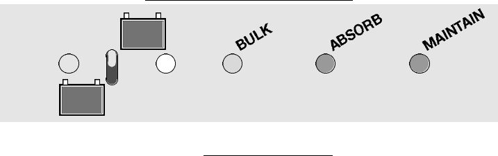
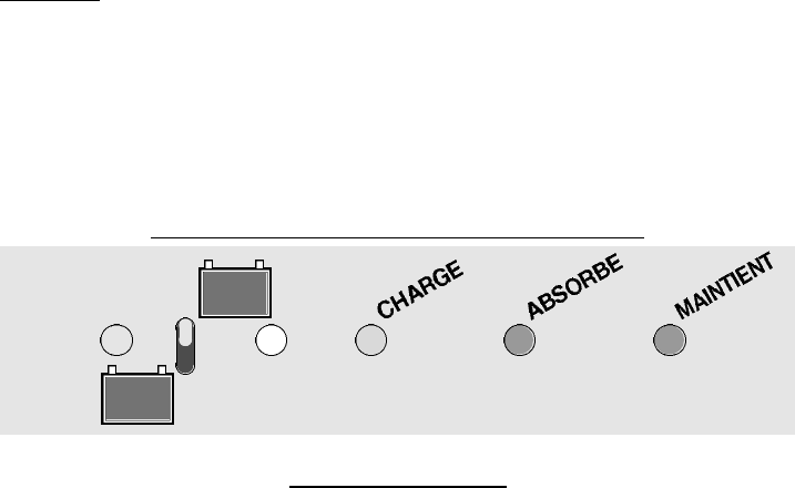
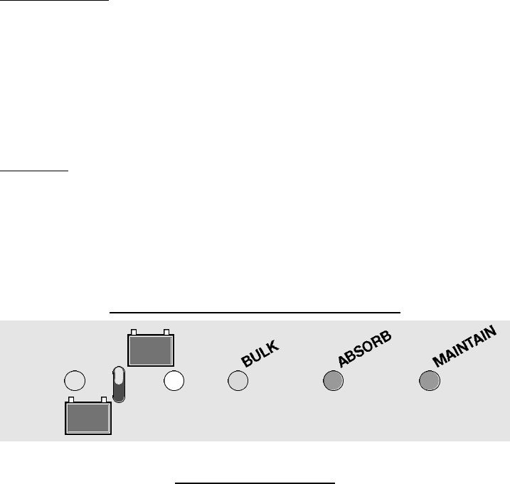
sulfatación). NOTA : Si solo se ilumina el LED de «POWER ON» después de comprobar la conexión correcta, la tension
inicial de la batería estará por debajo de 2V (para baterias de 12V) o de 4V (para una bateria de 24V) y es probable que
no se pueda recuperarla. Mientras el cargador esté conectado a la red CA y la batería,el estado vendrá indicado por un
LED,según el panel arriba indicado.
5)
El cargador cargará la batería automáticamente, y la mantendrá muy cerca de su capacidad de carga plena, a
menos que esté defectuosa la batería.Durante el ciclo «PRINCIPAL» de «BULK» (LED AMARILLA de carga),se carga la
batería a una corriente de salida máxima, hasta una tensión de 14,4V – o de 28,8V si esta una bateria de 24V - a una
temperatura de 20°C (68°F); luego la carga se conmuta al modo «flotante» (LED «ABSORB») con la tensión máxima de
14,4V (o de 28,8V).Ahora el cargador vigila la corriente de entrada a la batería, y cuando ésta se ve reducida al sixto
de su valor, se reducirá automáticamente la tensión de carga hasta 13,7V - o hasta 27,4V si esta una bateria de 24V
– a una temperatura de 20°C (68°F).
El LED VERDE («MAINTAIN») se encenderá para indicar que la baterla está lista. Mientras que se deja la tensión de
carga máxima a 13,7V (o de 27,4V), el cargador seguirá manteniendo la batería, permitiendo la entrada de corriente
si es necesario para compensar alguna descarga leve o carga de la batería si se deja conectada al circuito del vehi-
culo,durante todo el tiempo que permanezca conectada la batería.
6)
Si la batería demanda una corriente superiora al sexto del la corriente nominal, el circuito volvera automaticamente
al ciclo “ABSORB” hasta que la corriente se hubiera bajado a un nivel igual al sexto de la corriente máxima. En este
momento,volvera otra vez al ciclo «MAINTAIN».
7)
Se recomienda desconectar la red CA antes de desconectar la batería, aunque el circuito desactivará instantánea-
mente la salida de carga al desconectar la batería.
8) Ver la sección siguiente,sobre pistas para las aplicaciones e interpretación de las indicaciones LED,para aprovechar
la eficacia del AccuMate Pro.
PISTAS PARA LAS APLICACIONES E INTERPRETACIÓN DE LAS INDICACIONES «LED»
DEL ESTADO DE LA BATERÍA
Pistas Generales:
El AccuMate ha sido disehado para cargar las baterías de plomo-ácido de 12 o 24V que hayan
sufrido una descarga durante su funcionamiento normal, y que no hayan sufrido daños provocados por la falta pro-
longada de utilización, abuso fisico o defectos internos. La falta prolongada de utilización de una batería, cuando se
permite su descarga sin volver a cargarla,provoca un cambio quimico interno (sulfatación) que no podrá corregir el
AccuMate Pro.Al incumplir el mantenimiento de los niveles de electrólito de las baterías,due requiere un relleno peri-
ódico de agua destilada,tambón podrá dañarse la batería,y en este caso tampoco podrá recuperarla el AccuMate Pro.
Es posible que aún se pueda recuperar este tipo de baterías descuidadas con un cargador profesional de tecnologia
avanzada, como el BatteryMate, aunque quizás sea imposible restablecer completamente su estado perfecto. Toda
batería no utilizada mantendrá su carga mejor si se almacena en un ambiente frío o fresco (pero NO helado). Cuanto
más caliente el ambiente,antes se descargará la batería.
1) Una vez conectado el AccuMate Pro a la batería, dejarlo conectado durante el tiempo máximo indicado para el tamaño
de la batería,según las indicaciones de la tabla que ofrecemos al final,o hasta due se observe una indicación constante
del LED verde «MAINTAIN».Si se desconoce la capacidad nominal de la batería,utilizar las indicaciones de categoría de
la tabla (ver el § 9). En la mayoría de los casos,la recarga de una batería descargada viene indicada por una indicación
constante del LED «BULK»,durante un tiempo que no superará el tiempo «máximo» indicado en la tabla,y seguido de una
indicación constante del LED verde «ABSORB» y, finalmente,por la indicacion constante «MAINTAIN». Una vez obtenida
la indicación constante del LED verde «MAINTAIN», se puede dejar la batería conectada al AccuMate Pro durante más
tiempo due el tiempo máximo,si se desea,por ejemplo,mantener la batería durante un periodo de tiempo en el due per-
manecerá inutilizada.Sin embargo, a menos que se haya obtenido una indicación constante del LED verde «MAINTAIN»
dentro del tiempo «máximo» indicado a continuación,la batería puede tener algún defecto o problema,en cuyo caso no
tiene sentido dejarla conectada más tiempo.
2) En caso que ningun LED se encienda cuando el cargador està conectado a la red,leer el punto 3 «procedemiento de
carga».
3) No existe indicación de led,excepto la activación («ON»).En este caso,leer el punto 4 de la seccion «procedimiento de
carga».
4) Indicación constante del led «BULK».DEJARLO conectado hasta el tiempo «máximo» indicado a continuación, o hasta
observar una indicación constante del led verde «MAINTAIN». En la mayoría de los casos, el programa de carga inten-
tará lievar la batería al estado verde dentro del periodo de tiempo indicado en la columna de «horas normale» de la tabla
que ofrecemos a continuación.Si el led verde «MAINTAIN» no da esta indicación dentro del tiempo «máximo»,es probable
que la batería sufra daños internos.
11
5) Indicacion permanente del LED «ABSORB». En este caso, significa que la carga se ha hecho al 70% de su capacidad
máxima.En este momento, ya se puede arrancar un motor pero,si se puede esperar, es siempre mejor dejar la batería
en carga hasta que el LED «MAINTAIN» se encienda.Las baterías de ciclo longo – como se utilizan para los caddies de
golf – debrian idealmente quedar conectadas tambien hasta que el LED «MAINTAIN» se encienda.
Si la bateria fue cargada dentro del vehículo y fue conectada al cargador durante un tiempo superior al maximum como
indicado por la tabla que ofrecemos a continuacion, puede ser dañada. En este caso, mandarla a un profesional para
controlarla.
6) Los LED «ABSORB» y «MAINTAIN» parpadean rápida y alternativamente. En este caso, podría indicar una descarga
demasiado profunda (o quizás una ligera sulfatación) de la batería que intenta recuperar el AccuMate Pro. Es posible que
ocurra alando la batería sufre algún defecto interno, aunque el AccuMate Pro sigue intentando recuperarla. DEJARLO
conectado hasta el tíempo «máximo» indicado a continuación.Si este fenomeno persiste,tendria que mandar la bateria a
un profesional.
7)
Indicación constante del led verde «MAINTAIN». La batería está completamente cargada y lista para utilizar. Sin
embargo,se puede dejar conectada al AccuMate Pro de forma continua si se desea mantener la carga completa durante
un cierto período de inutilización,incluso durante muchas meses.
NOTA: Si se da el caso de una indicación constante del LED verde immediatamente después de conectar una batería
cuya descarga, descarga profunda o inutilización durante meses antes de la conexión está comprobada, es probable
que sufra una descarga profunda. En este caso, dejarlo conectado durante el tiempo «máximo» de carga, según la
tabla.
Si el LED verde y/o amarillo parpadea en este período, ver el § 6 arriba indicado. Si después resulta inutilizable la
batería, Ilevarla a un concesionario de servicio profesional que disponga de un cargador recuperativo/probador de
carga BatteryMate.
8) La tabla que ofrecemos a continuación refleja los tiempos máximos aproximados de carga,desde un estado de batería
completamente descargada hasta el estado de carga completa. Este tiempo equivale aproximadamente a la capacidad
nominal en horas-amperio de la batería; por lo tanto, si esta capacidad viene impresa en la batería, se puede calcular
fácilmente una estimación.Sin embargo,sólo se dan los casos de haber dejado encendidos los faros del coche durante
una semana,o de haber dejado la batería sin utilizar y dentro de un ambiente caliente durante meses con el resultado de
una batería completamente descargada. La columna de «Tiempo normal desde descarga completa»,indica los tiempos
medios de carga para obtener una carga completa de la batería,a partir de un voltaje minimal de 2V.
9) Tablero
Capacidad Tiempo normal desde
Tiempo máximo
batería descargada completa en horas
Vehiculo o applicación
horas- CORRIENTE DE CARGA
amperio 4A 6A 7A 3,5A 4A 6A 7A 3,5A
Caddy golf,grande moto,tractor de jardin 18 a 130 14 - 17 13 - 15 13 - 24 15 - 18 12 8 7 14
Caddy lordo,pequeño coche 31 a 144 16 - 10 14 - 17 14 - 26 18 - 12 17 12 10 20
Coche mediano 45 a 155 10 - 15 17 - 10 16 - 28 12 - 16 24 16 14 28
Coche grande,pequeña embarcacion 56 a 175 13 - 20 19 - 13 18 - 11 16 - 22 32 21 18 36
Limousine,camionnetta,4x4,embarcacion mediana
176 a 100 18 - 26 12 - 17 10 - 15 20 - 30 45 30 26 52
Embarcacion grande,camion,tractor 101 a 150 25 - 37 17 - 24 15 - 21 30 - 42 60 40 35 70
12
LIMITED WARRANTY
TecMate Powersports Products North America Inc.,Unit 22,1100 Invicta Drive,Oakville ONL6H 2K9,Canada,makes this
limited warranty to the original purchaser at retail of this product.This limited warranty is not transferable.
TecMate warrants this battery charger for two years from date of purchase at retail against defective material or work-
manship.If such should occur the unit will be repaired or replaced at the option of the manufacturer. It is the obligation of
the purchaser to forward the unit together with proof of purchase,transportation or mailing costs prepaid, to the manu-
facturer or their authorized representative.This limited warranty is void if the product is misused, subjected to careless
handling,or repaired by anyone other than the factory or its authorised representative.Any damage to the unit,it’s leads
or accessory parts resulting from acid or fluid contamination,exposure to damp or humidity or from physical damage is
NOT covered by warranty. The manufacturer makes no warranty other than this limited warranty and expressly excludes
any implied warranty including any warranty for consequential damages.
THIS IS THE ONLY EXPRESS LIMITED WARRANTY AND THE MANUFACTURER NEITHER ASSUMES NOR A U T H O R I Z E S
ANYONE TO ASSUME OR MAKE ANY OTHER OBLIGATION T O WARDS THE PRODUCT OTHER THAN THIS EXPRESS LIMITED
WA R R A N T Y. S t at u t o ry rights not infringed.
GARANTIE RESTREINTE
La présente garantie restreinte est consentie par TecMate Powersports Products North America Inc.,Unit 22,1100 Invicta
Drive, Oakville ONL6H 2K9, Canada, à tout premier acheteur de I’appareil. Cette garantie n’est pas transférable. Cette
garantie couvre toutes les pièces reconnues défectueuses et la main-d’oeuvre,pendant 2 ans à partir du jour de I’achat
du chargeur par son premier propriétaire. Si le chargeur s’avère fectueux par suite d’un vice de construction, i l
appartiendra au client de retourner I’appareil au fabricant ou à son concessionnaire national agréé, accompagné d’une
copie de la facture d’achat , les frais de port étant toujours réglés anticipativement par le cl i e n t . Les dégats découlant
d’un accident, d’une négligence, de malveillance, d ’ a b u s , d ’ a c i d e , d’humidité et dune utilisation non conforme aux
p r e s c r i p t i o n s du mode d’emploi,ne sont pas couverts par la garantie.
La garantie exclut expressément toute responsabilité quant à d’autres conséquences dommageables éventuelles, de
quelque nature que celles-ci puissent être.
LA PRESENTE GARANTIE RESTREINTE OFFERTE POUR LE CHARGEUR EST LE SEUL ENGAGEMENT VALABLE RECONNU PAR
LE FABRICANT, CELUI-CI EXCLUANT EXPRESSEMENT TOUTE AUTRE FORME DE GARANTIE OU D’ENGAGEMENT.
GARANTIA LIMITADA
TecMate Powersports Products North America Inc.,Unit 22,1100 Invicta Drive,Oakville ONL6H 2K9,Canada,otorga esta
garantia limitada al comprador original de este producto.Esta garantia limitada no es transferible. TecMate (International)
garantiza este cargador de baterías por dos años a partir de la fecha de venta al menudeo por materiales defectuosos
o manufactura. En caso de que esto suceda, la unidad sera reparada o reemplazada en opción del fabricante o su repre-
sentante autorizado.Es la obligación del comprador de remitir la unidad incluyendo prueba de compra, cargos de trans-
portación o gastos de correo deberan ser previamente pagados al manufacturador o su representante autorizado. La
garantia limitada pierde su validez si el producto es maltratado,manejado descuidadamente o reparado por alguna per-
sona no autorizada por la fabrica o algun representante de la misma.Ningún daño a la unidad,sus cables o piezas acce-
sorias como resultado de contaminación de ácido o de líquido,exposición a la humedad o debido a un daño físico NO ESTÁ
cubierto por la garantía.El fabricante no hace ninguna otra garantia,fuera de la garantia limitada y expresamente excluye,
cualesquier garantia implicada incluyendo garantia por daños de consecuencia.
E S TA ES LA UNICA GARANTIA LIMITADA Y EL FABRICANTE NO A C E P TA ASUME O AUTORIZA A NADIE A QUE A S U M A ,
ACEPTE NINGUNA OTRA OBLIGACION HACIA ESTE PRODUCTO,FUERA DE LA EXPRESA GARANTIA LIMITADA.
4


Need help? Post your question in this forum.

Forumrules


Report abuse

Libble takes abuse of its services very seriously. We're committed to dealing with such abuse according to the laws in your country of residence. When you submit a report, we'll investigate it and take the appropriate action. We'll get back to you only if we require additional details or have more information to share.

Product:

For example, Anti-Semitic content, racist content, or material that could result in a violent physical act.

For example, a credit card number, a personal identification number, or an unlisted home address. Note that email addresses and full names are not considered private information.

Forumrules

To achieve meaningful questions, we apply the following rules:

Register

Register getting emails for Tecmate ACCUMATE PRO at:


You will receive an email to register for one or both of the options.


Get your user manual by e-mail

Enter your email address to receive the manual of Tecmate ACCUMATE PRO in the language / languages: English, French, Spanish as an attachment in your email.

The manual is 0,23 mb in size.


You will receive the manual in your email within minutes. If you have not received an email, then probably have entered the wrong email address or your mailbox is too full. In addition, it may be that your ISP may have a maximum size for emails to receive.

The manual is sent by email. Check your email

If you have not received an email with the manual within fifteen minutes, it may be that you have a entered a wrong email address or that your ISP has set a maximum size to receive email that is smaller than the size of the manual.

The email address you have provided is not correct.

Please check the email address and correct it.

Your question is posted on this page

Would you like to receive an email when new answers and questions are posted? Please enter your email address.


Info