5.Merkmale und Funktionen.............................................................................................................................7
7.Batterie- und Akkuhinweise......................................................................................................................... 11
9.Vorbereitung zum Betrieb ............................................................................................................................ 14
a)Rückseite der Wetterstation...................................................................................................................... 14
b)Anschluss des Netzteils............................................................................................................................ 15
b)Batterien und Akkus .................................................................................................................................. 49
17.Anschluss an den Computer....................................................................................................................... 50
22.Menüstruktur der "WS550" ..........................................................................................................................56
Beginnender Regen wird bei der nächsten Funk-Datenübertragung der Basisstation gemeldet und durch eine
Regenwolke im Feld "RAIN" und durch den geöffneten Regenschirm von "Wetter-Willi" dargestellt.
XX
XX
X 6. Komfort-Indikator
Der Komfort-Indikator (
☺
) gibt das Raumklima (Verhältnis von Temperatur zu Luftfeuchte) wieder. Eine
Wertetabelle zu den Anzeigebereichen finden Sie im Anhang.
XX
XX
X 7. Verlaufsanzeige ("History")
Das Balkendiagramm zeigt den Verlauf des Luftdrucks, der Außen- oder der Innentemperatur für die letzten 24
Stunden an. Die einzelnen Säulen stellen hierbei keinen absoluten Wert dar, sondern die Differenz zum aktuellen
Messwert (0h-Säule). Dieser Bezugspunkt befindet sich immer in der Mitte (4 Balken), damit die Tendenz auf den
ersten Blick erkennbar ist.
XX
XX
X 8. Datenspeicher
Ist der Datenspeicher fast voll, erscheint in der Menüzeile die Meldung:
MEMORY ALMOST FULL OK MEMORY ALMOST FULL OK
MEMORY ALMOST FULL OK MEMORY ALMOST FULL OK
MEMORY ALMOST FULL OK
Berühren Sie zur Bestätigung dieses Eingabefeld und lesen Sie die gesammelten Daten über den Computer aus.
XX
XX
X 9. Datenübertragung an den Kombisensor ("WAIT FOR TRANSMISSION")
Erscheint in der Menüzeile "WAIT FOR TRANSMISSION", so überträgt die Wetterstation Daten an den Kombi-
sensor, z. B. die Aktivierung des Live-Modus oder die Konfigurationsdaten der Sonnenscheindauer.
Dieser Vorgang kann bis zu einigen Minuten dauern, in dieser Zeit ist keine Bedienung der Wettersta-
tion möglich.
XX
XX
X 10. Temperatur-Tendenz-Anzeige
Rechts neben den Temperatur-Anzeigen in den Anzeigefeldern "INDOOR" und "OUTDOOR" erscheint ein
Tendenzpfeil, falls sich die Temperatur im letzten Sendeintervall nach oben (Pfeil nach oben) oder unten (Pfeil nach
unten) verändert hat.
40
XX
XX
X 11. Sensor-Status-Anzeige
Im Außensensor-Anzeigefeld ("OUTDOOR") wird über ein kleines Funkturm-Symbol der Status des Sensors
angezeigt:
Funkturm-Symbol erscheint konstant¨Sensor wird korrekt empfangen
Funkturm-Symbol blinkt¨Sensor wird seit 40 Minuten nicht empfangen
Funkturm-Symbol fehlt¨Sensor nicht vorhanden, dauerhaft gestört oder defekt
XX
XX
X 12. Funkuhr-Empfang
•Direkt nach dem Einschalten startet die Wetterstation den Versuch, das Zeitsignal des Zeitzeichensenders
DCF77 zu empfangen, um automatisch die aktuelle Uhrzeit einzustellen.
•Empfängt die Wetterstation das Zeitsignal, werden Zeit und Datum automatisch aktualisiert und es erscheint ein
kleines Funkturmsymbol zwischen diesen Angaben.
•Täglich um 04:00 Uhr startet die Wetterstation einen Synchronisationsversuch mit dem DCF-77-Sender.
•Ist kein DCF77-Empfang möglich, arbeitet die interne Uhr als Quarzuhr.
•Der DCF-77-Empfang ist bei Bedarf abschaltbar (siehe Menü "SYSTEM/DCF").
XX
XX
X 13. Warnung vor markantem Wetter
Im Wettervorhersage-Anzeigefeld erscheint ein Warnschild-Symbol, wenn der Luftdruck stark in kurzer Zeit fällt.
Dies weist z. B. auf einen aufziehenden Sturm oder ein Gewitter hin.
XX
XX
X 14. Frostwarnung
Im Wettervorhersage-Anzeigfeld erscheint ein Schneeflocken-Symbol, wenn die gemessene Temperatur am
Kombisensor unter +4°C fällt.
41
11. Batteriewechsel
a) Basisstation
Erscheint im Display das Batterie-Leer-Symbol ( ), so sind alle Batterien nach Kapitel 9. a) bzw. 9. c) gegen
neue auszutauschen.
Wechseln Sie stets alle 4 Batterien aus und setzen Sie nur hochwertige Alkaline-Batterien ein. Lassen
Sie während des Batteriewechsels immer das Netzteil angeschlossen, um einen Verlust von Daten zu
vermeiden.
Bitte beachten Sie:
Ist kein Netzteil angeschlossen, wird bei einem Batteriewechsel der Datenspeicher gelöscht, alle
Messwerte sind gelöscht.
b) Funk-Sensoren
Die Batterien in diesen Sensoren haben eine Lebensdauer von bis zu 2 Jahren (Alkaline-Batterien). Sie sind zu
wechseln, wenn im Sensorfeld "OUTDOOR" bei Anwahl des entsprechenden Sensors ein Batterie-Leer-Symbol
( ) erscheint.
Der Batteriewechsel des Kombisensors erfolgt wie im Kapitel 9. g) beschrieben, der der weiteren Sensoren wie in
deren Bedienungsanleitung beschrieben.
42
12. Hinweise zur Störungsbeseitigung
Mögliche Störungen, die die ordnungsgemäße Anzeige der gesendeten Messwerte behindern, sind:
•Kein Empfang
¨Der Abstand zwischen Sender und Empfänger ist zu groß oder zu gering (<1 m). Abstand zwischen Sender/
Empfänger verringern/erhöhen.
¨Stark abschirmende Materialien befinden sich zwischen Sender und Empfänger (dicke Wände, Stahlbeton,
usw.). Wählen Sie eine andere Position für Sender bzw. Empfänger. Siehe dazu auch das Kapitel
"Reichweite".
¨Die Batterien der Sensoren sind leer, wechseln Sie die Batterien.
¨Der Sender wird von Störquelle überlagert (Funkgerät, Funkkopfhörer/-lautsprecher). Beseitigen Sie die
Störquelle oder wählen Sie eine andere Position für Sender und Empfänger.
Werden in Ihrem Haus oder in der Nachbarschaft z.B. Funkkopfhörer, Funk-Babyüberwachungsgeräte oder
ähnliche Geräte auf 868 MHz betrieben, ist deren Einschaltdauer normalerweise zeitlich begrenzt, die
Störungen treten nur zeitweise auf.
Möglicherweise lässt sich auf diesen Geräten eine andere Sendefrequenz einstellen, was die Störungen
beim Betrieb der Wetterstation beseitigen kann.
•Funksensor stört andere Geräte im 868MHz-Bereich
¨Die Aussendungen des Funk-Außensensors können kurzzeitig (alle 2-3 min für ca. 100 ms) andere auf dem
gleichen Kanal arbeitende Geräte stören.
Dies äußert sich z.B. bei manchen Funkkopfhörern als kurzes Störgeräusch.
Falls möglich, so wählen Sie auf dem von Ihnen verwendeten Gerät (z.B. Funkkopfhörer usw.) eine andere
Sende-/Empfangsfrequenz.
Weitere Hinweise zur Inbetriebnahme bzw. Störungsbeseitigung
Drehen Sie ggf. die Wetterstation ein wenig, stellen Sie diese bei mangelndem Empfang entfernt von Elektromoto-
ren, elektrischen Maschinen, Fernsehgeräten, Computermonitoren und großen Metallflächen auf.
Zur einfacheren Inbetriebnahme können Sie die Sensoren zunächst auch in die Nähe des Basisgerätes bringen
(mind. 1 m Abstand). Hier lässt sich zunächst die ordnungsgemäße Datenaussendung des Sensors und damit die
Funktion der Wetterstation kontrollieren.
Die Sensoren müssen ordnungsgemäß an der Wetterstation angemeldet sein, sonst werden deren Daten nicht
angezeigt.
43
13. Reichweite
Die Freifeldreichweite, d. h. die Reichweite bei Sichtkontakt zwischen Sender und Empfänger, beträgt unter
optimalen Bedingungen 300 m. Wände und selbst Stahlbetonkonstruktionen können durchdrungen werden, wobei
sich die Reichweite jedoch entsprechend reduziert.
Eine verminderte Reichweite kann folgende Ursachen haben:
•Hochfrequenzstörungen aller Art
•Bebauung jeder Art oder Vegetation
•Der Abstand des Senders oder Empfängers zu leitenden Flächen oder Gegenständen (auch zum menschlichen
Körper oder Erdboden) beeinflusst die Strahlungscharakteristik und somit die Reichweite.
•Breitbandstörungen in Stadtgebieten können Pegel erreichen, die den Signal-Rauschabstand im gesamten
Frequenzband verkleinern, wodurch sich die Reichweite verringert.
•Geräte mit benachbarten Arbeitsfrequenzen können ebenfalls den Empfänger beeinflussen.
•Schlecht abgeschirmte bzw. offen betriebene Computer können in den Empfänger einstrahlen und die Reichweite
vermindern.
Da die örtlichen Gegebenheiten an jedem Aufstellungsort anders sind, kann eine bestimmte Reich-
weite nicht garantiert werden.
Normalerweise ist jedoch der Betrieb in einem Einfamilienhaus ohne Probleme möglich. Wenn die
Basisstation keine Daten von einem bzw. mehreren Außensensoren erhält (trotz neuer Batterien), so
verringern Sie die Entfernung zwischen Außensensor(en) und Basisstation, wechseln Sie den
Aufstellungsort.
44
14. Wartungs- und Pflegehinweise
a) Allgemein
Eine Wartung oder Reparatur ist nur durch eine Fachkraft oder Fachwerkstatt zulässig.
Durch unsachgemäße Arbeiten erlischt nicht nur die Zulassung (CE), sondern auch die Garantie/
Gewährleistung. Außerdem besteht die Gefahr eines lebensgefährlichen elektrischen Schlages.
Es sind keinerlei für Sie zu wartende Bestandteile im Inneren der Bestandteile des Produkts, öffnen Sie es deshalb
niemals (bis auf die in dieser Bedienungsanleitung beschriebenen Arbeiten, z.B. Montage, Einlegen oder Wechseln
der Batterien usw.).
Überprüfen Sie regelmäßig die technische Sicherheit des Produkts, z.B. Beschädigung des Gehäuses.
Wenn anzunehmen ist, dass ein gefahrloser Betrieb nicht mehr möglich ist, so ist das Produkt außer Betrieb zu
setzen und gegen unbeabsichtigten Betrieb zu sichern. Entnehmen Sie die Batterien, trennen Sie die Wetterstation
von dem Steckernetzteil, ziehen Sie das Steckernetzteil aus der Netzsteckdose.
Es ist anzunehmen, dass ein gefahrloser Betrieb nicht mehr möglich ist, wenn
•das Gerät sichtbare Beschädigungen aufweist,
•das Gerät nicht mehr funktioniert und
•nach längerer Lagerung unter ungünstigen Verhältnissen oder
•nach schweren Transportbeanspruchungen.
b) Reinigung der Basisstation
Vor der Reinigung des Displays ist die Basisstation in den "Cleaning-Modus" zu versetzen, wie in Kapitel 11. c)
beschrieben. Andernfalls werden durch die Berührung des Displays beim Reinigungsvorgang diverse Funktionen
ausgelöst, was zu ungewollten Effekten führen kann.
Verwenden Sie für die Reinigung des Displays ausschließlich ein weiches, sauberes und trockenes
Tuch. Ideal geeignet ist ein Brillenputztuch.
Verwenden Sie keine rauhen Tücher, verwenden Sie niemals Reinigungsflüssigkeiten! Dadurch wird
die berührungsempfindliche Oberfläche des Displays beschädigt.
Staub kann z.B. mit einem weichen, sauberen Pinsel und einem Staubsauger entfernt werden.
Üben Sie beim Reinigen keinen starken Druck auf das Display aus.
45
c) Reinigung der Außensensoren
Für Verschmutzungen der Außensensoren kann ein mit lauwarmen Wasser angefeuchtetes Tuch verwendet
werden.
Verwenden Sie auf keinen Fall aggressive Reinigungsmittel, Reinigungsalkohol oder andere chemi-
sche Lösungen, da dadurch das Gehäuse angegriffen oder gar die Funktion beeinträchtigt werden
kann.
Spritzen Sie die Außensensoren auf keinen Fall z.B. mit einem Gartenschlauch ab, da die Außen-
sensoren nur gegen Regen von oben geschützt sind und nicht gegen Strahlwasser von den Seiten oder
unten.
d) Reinigung des Regenmengen-Sensors
Je nach Standort gelangen Blätter, mit dem Wind getragene Schmutzpartikel, Sand, kleine Äste u.a. in den
Auffangtrichter des Regenmengensensors. Größere Teile können dabei den Durchfluss verstopfen.
Sie sollten deshalb den Auffangtrichter regelmäßig kontrollieren. , ob sich darin z.B. Blätter befinden. Entfernen Sie
diese.
Innen im Regenmengen-Sensor befindet sich die Zählwippe. In dieser kann sich Sand/Staub ansammeln, der mit
zunehmender Menge das Messergebnis verfälscht.
Deshalb ist der Regenmengen-Sensor gelegentlich zu zerlegen und die Zählwippe zu reinigen. Wir
empfehlen Ihnen, diese Reinigung mindestens einmal im Jahr vorzunehmen.
Gehen Sie zum Zerlegen bzw. Zusammenbauen des Regenmengen-Sensors wie folgt vor:
1.Öffnen Sie das Unterteil des Regenmengen-Sensors, drehen Sie dazu
das Unterteil ca. 1cm nach links, bis Sie es am Metallrohr nach unten
gleiten lassen können.
Nehmen Sie anschließend den oberen Auffangtrichter ab, indem Sie
ihn vorher ein kleines Stück nach rechts drehen; danach heben Sie ihn
nach oben ab.
Merken Sie sich die Orientierung der Rastnasen.
2.Der Regenfall-Sensor (das Kunststoffteil mit den beiden Messingstiften und dem Kabel) kann jetzt herausgenom-
men werden.
Merken Sie sich die Orientierung, an einer Seite befindet sich das Verbindungskabel des Regenfall-
Sensors.
3.Nehmen Sie die Zählwippe heraus.
Merken Sie sich die Orientierung, an einer Seite der Zählwippe befindet sich ein kleiner Magnet.
¨
¨
¨
¨
1
2
34
46
4.Reinigen Sie nun die Bestandteile des Regenmengensensors. Denken Sie auch an das Ablaufloch im Kunststoff-
Unterteil des Regenmengensensors, das Sie am Metallrohr nach unten geschoben haben.
5.Zum Zusammenbau setzen Sie zuerst die Zählwippe in die
Halterung ein.
Dabei muss sich der Magnet der Zählwippe auf
der Seite befinden, die zum Kabel zeigt.
Die beiden unteren Trapezstifte müssen im unte-
ren Teil der Halterung richtig eingesteckt wer-
den.
Nur dadurch ist gewährleistet, dass sich die Zähl-
wippe leicht bewegt.
6.Stecken Sie den Regenfall-Sensor in seine Halterung ein.
Er hält automatisch auch die Zählwippe fest.
Nur eine Orientierung ist richtig.
Das Kabel des Regenfall-Sensors und der Ma-
gnet der Zählwippe müssen sich auf der gleichen
Seite befinden.
Die Kunststoffnase auf der anderen Seite muss
genau in die Halterung eingesteckt sein!
7. Setzen Sie den Auffangtrichter von oben auf den Sensorträger und
rasten Sie ihn durch Linksdrehen ein.
Schließen Sie das Unterteil des Regenmengen-Sensors.
¨
¨
¨
¨
4
3
2
1
47
e) Regensensor abgleichen
Das Regenmengen-Messsystem besitzt bereits ab Werk eine hohe Genauigkeit, so dass ein Abgleich
im Normalfall nicht erforderlich ist.
Ein Abgleich wird nur bei sehr hohen Genauigkeitsforderungen erforderlich werden.
Der Abgleichvorgang dauert recht lange (mind. 10 Minuten) und muss sehr genau und gewissenhaft
durchgeführt werden, da ansonsten die Genauigkeit viel geringer ist als die bereits vorhandene.
Bevor Sie mit dem Abgleich des Regen-Messwertaufnehmers beginnen, ist im normalen Anzeigemode
ein bereits evtl. aufsummierter Regenmengenwert auf Null zurückzusetzen (Gesamt-Regenmengen-
anzeige steht auf Null).
Außerdem muss die Regenmenge für den Abgleich in "mm" oder "l/m²" angezeigt werden. Stellen Sie
die Anzeige-Einheit richtig ein.
Kontrollieren Sie auch, ob der Regenmengensensor sauber ist (Auffangtrichter, Ablauföffnung,
Zählwippe) und die Zählwippe trocken ist.
Für die exakte Kalibrierung gehen Sie dann wie folgt vor:
1. Gießen Sie sehr langsam, über 10 Minuten verteilt, 100 ml Wasser in den Regensensor-Auffangtrichter.
Achtung!
Schnelles Gießen verfälscht das Messergebnis! Gießen Sie das Wasser so langsam in den Trichter,
dass zu keinem Zeitpunkt Wasser im Trichter steht.
Bedenken Sie, dass selbst bei sehr starken Niederschlägen nur wenige Regentropfen in die Öffnung
des Regensensors fallen.
2. Die angezeigte Gesamtmenge sollte jetzt 6,5 l/m² betragen.
3. Wird ein abweichender Wert angezeigt, so ist der so genannte Wippenwert wie folgt neu zu berechnen:
6,5 x aktueller Wippenwert
Neuer Wippenwert =
Istwert (Anzeige nach dem Einfüllen des Wassers)
4.Im Konfigurationsmenü (Systemmenü "RAIN CAL") muss jetzt der neue Wippenwert eingetragen werden. Er wird
immer in ml/Wippenschlag angegeben.
Die werkseitige Einstellung ist 295 ml/Wippenschlag.
48
15. Handhabung
Beachten Sie sämtliche Sicherheitshinweise dieser Bedienungsanleitung!
a) Allgemein
Das Produkt darf nicht geöffnet oder zerlegt werden (bis auf die in dieser Bedienungsanleitung beschriebenen
Arbeiten zum Einlegen der Batterien, zur Montage bzw. zur Reinigung des Regenmengensensors).
Durch den Fall aus bereits geringer Höhe wird das Produkt beschädigt.
b) Basisstation
•Vermeiden Sie folgende widrige Umgebungsbedingungen beim Aufstellen und bei Betrieb der Basisstation:
-Nässe oder zu hohe Luftfeuchtigkeit
-Extreme Kälte oder Hitze
-Direkte Sonneneinstrahlung
-Staub oder brennbare Gase, Dämpfe oder Lösungsmittel
-starke Vibrationen
-starke Magnetfelder, wie in der Nähe von Maschinen oder Lautsprechern
•Verwenden Sie das Basisstation und Steckernetzteil niemals gleich dann, wenn es von einem kalten in einen
warmen Raum gebracht wird. Das dabei entstehende Kondenswasser kann unter Umständen das Produkt
zerstören.
Außerdem besteht beim Steckernetzteil Gefahr durch einen elektrischen Schlag!
Warten Sie, bis die Basisstation und das Steckernetzteil auf Zimmertemperatur gekommen ist. Dies kann mehrere
Stunden dauern.
•Der Aufstellungsort soll so gewählt werden, dass die Basisstation sicher steht und nicht herunterfallen kann.
Durch das hohe Gewicht besteht sonst Verletzungsgefahr.
Wählen Sie eine ebene, ausreichend große Fläche als Aufstellort.
•Wertvolle oder kratzempfindliche Möbeloberflächen sollten Sie mittels geeigneter Unterlagen vor Beschädigung
schützen, bevor Sie die Basisstation aufstellen.
49
c) Kombisensor
Der mitgelieferte Kombisensor ist geeignet zum Betrieb im ungeschützten Außenbereich.
Vermeiden Sie jedoch unbedingt das direkte Anspritzen z.B. über einen Gartenschlauch oder einem
anderen Bewässerungssystem.
Wählen Sie den Aufstellungsort so, dass Kinder den Kombisensor nicht umkippen können; stellen Sie den
Kombisensor nicht in der Nähe von Fahrzeugen, Glastüren/-fenstern o.ä. auf!
16. Entsorgung
a) Allgemein
Entsorgen Sie das Produkt am Ende seiner Lebensdauer gemäß den geltenden gesetzlichen
Bestimmungen.
b) Batterien und Akkus
Sie als Endverbraucher sind gesetzlich (Batterieverordnung) zur Rückgabe aller gebrauchten Batterien und Akkus
verpflichtet; eine Entsorgung über den Hausmüll ist untersagt!
Schadstoffhaltige Batterien/Akkus sind mit nebenstehenden Symbolen gekennzeichnet, die auf das
Verbot der Entsorgung über den Hausmüll hinweisen. Die Bezeichnungen für das ausschlaggebende
Schwermetall sind: Cd=Cadmium, Hg=Quecksilber, Pb=Blei (Bezeichnung steht auf der Batterie/Akku
z.B. unter den links abgebildeten Mülltonnen-Symbolen).
Ihre verbrauchten Batterien/Akkus können Sie unentgeltlich bei den Sammelstellen Ihrer Gemeinde,
unseren Filialen oder überall dort abgeben, wo Batterien/Akkus verkauft werden!
Sie erfüllen damit die gesetzlichen Verpflichtungen und leisten Ihren Beitrag zum Umweltschutz.
50
17. Anschluss an den Computer
Die "WS550" kann über USB an einen Computer (Betriebssystem Windows XP, Windows 2000 oder höher)
angeschlossen werden.
Hierüber ist dann das Auslesen der gespeicherten Messwerte und die Auswertung der Daten möglich.
Bitte beachten Sie die Bedienungsanleitung zur Software.
Für den Betrieb der Software "WeatherPro Edition 2007" gelten folgende Systemvoraussetzungen:
•Betriebssystem Windows 2000/XP
•Taktfrequenz mind. 1GHz
•Arbeitsspeicher mind. 256MByte
•Erforderlicher Platz auf der Festplatte für das Programm: Ca. 150MByte
•Erforderlicher Platz für die Datenbank: Ca. 100MByte
•Festplatte muss mit dem Dateisystem "NTFS" formatiert sein (FAT32 ist nicht möglich für die Datenbank!)
•Der Windows-Installer-Service muss installiert sein (Standard-Option von Windows)
•Ein freier USB-Port
Gehen Sie wie folgt vor:
•Schließen Sie die Wetterstation über das USB-Kabel an einen freien USB-Port des Rechners an.
•Nach kurzer Zeit erkennt der Computer das Vorhandensein eines neuen USB-Gerätes und verlangt nach einem
Treiber. Der Installationsassistent erscheint.
•Legen Sie die mitgelieferte CD in das entsprechende Laufwerk Ihres Computers ein und warten Sie, bis deren
Willkommens-Bildschirm erscheint.
•Gehen Sie in den Installationsassistenten und wählen Sie hier die Option "Automatisch suchen".
•Folgen Sie den Anweisungen des Installationsassistenten bis zum Abschluss der Treiberinstallation.
•Gehen Sie in das "WeatherPro Edition 2007 Setup", das die vier Schritte für das Setup beschreibt. Beginnen Sie
hier bei Punkt 2.
•Folgen Sie diesen Anweisungen Schritt für Schritt bis zum Abschluss der Installation. Anschließend kann das
Programm "WeatherPro Edition 2007" über den Desktop oder das Programmmenü gestartet werden.
•Die Programmbeschreibung finden Sie im Hilfemenü unter "Handbuch".
51
18. Firmware-Update
Ein Firmware-Update des Haupt-Controllers der "WS550" kann mit Hilfe der mitgelieferten Software über die USB-
Schnittstelle der WS550 vorgenommen werden.
Starten Sie in der "Weather Pro Ediotion 2007"-Software das Update-Programm (Menü "Extras", Menüpunkt
"Firmware-Update") und folgen Sie den Anweisungen des Programms.
Hinweis:
Sollten Sie die Update-Prozedur aus Versehen gestartet haben, so kann diese bis Schritt 5 jederzeit
abgebrochen werden.
Falls der Update-Modus entsprechend den Hinweisen der Software auch am Gerät aktiviert wurde, so
ist die Wetterstation für einige Sekunden vom USB und Steckernetzteil zu trennen und die Batterien
sind aus dem Gerät zu entfernen. Die Funktion des Gerätes wird hierdurch nicht beeinträchtigt, es
arbeitet nach Wiederinbetriebnahme mit der bisherigen Firmware weiter.
52
19. Technische Daten
Messintervall Außensensoren:.......................................................................................................................2-3 min
Messintervall Innensensor (Temperatur, Luftfeuchtigkeit):.............................................................................. 3 min
Messintervall Luftdruck:....................................................................................................................................15 min
Freifeldreichweite:....................................................................................................................................max. 300 m
Temperaturbereich innen:................................................................................................................... 0°C bis +60°C
Genauigkeit:........................................................................................................................±1°C (+15°C bis +40°C)
Temperaturbereich außen (Kombisensor):..............................................................................-19,9°C bis +79,9°C
Genauigkeit:.....................................................................................................................±0,8°C (+10°C bis +40°C)
Messbereich rel. Luftfeuchtigkeit (innen/außen):.........................................................................1% rH bis 99% rH
Genauigkeit:......................................................................................................................... ±5% rH (30 bis 70% rH)
Regenmengenanzeige: .........................................................................................................................0 bis 999 mm
Auswertungsintervall:..........................................................................................................letzte Std: um xx:30 Uhr
....................................................................................................................................................... Tag: um 07:30 Uhr
Auflösung:................................................................................................................................ bis 100 mm: <0,3 mm
Windgeschwindigkeit:..........................................................................................................................0 bis 200 km/h
Auflösung:..............................................................................................................................bis 100 km/h: 0,1 km/h
................................................................................................................................................. über 100 km/h: 1 km/h
Windrichtung: ............................................................................................................................................0° bis 355°
3.Meaning of symbols...................................................................................................................................... 63
5.Features and functions.................................................................................................................................64
9.Preparation for operation.............................................................................................................................71
a)Back side of the weather station..............................................................................................................71
b)Connecting the mains adapter.................................................................................................................. 72
c)Inserting the batteries................................................................................................................................72
d)Connection to the computer...................................................................................................................... 72
General information...................................................................................................................................72
9.Data transmission to the combination sensor ("WAIT FOR TRANSMISSION") ............................. 96
10. Temperature trend display.................................................................................................................. 96
11. Sensor status display.......................................................................................................................... 97
12. DCF77 time signal............................................................................................................................... 97
13. Warning against heavy weather.........................................................................................................97
14. Low temperature alert......................................................................................................................... 97
13.Transmission range .................................................................................................................................... 100
14.Maintenance and care................................................................................................................................. 101
b)Batteries and rechargeable batteries ..................................................................................................... 106
17.Connection to the computer...................................................................................................................... 107
Please refer to the corresponding manuals for information on how to assemble, address and take these sensors into
operation.
81
10. Operation
After you have installed the wireless sensors and started the display console, the data of the wireless sensor will not
at once appear on the display.
Since each sensor has an individual serial number, it must be registered separately at the display console.
This method has the advantage that only individually registered sensors are detected and no sensors of a third
system nearby; this is also the case when the system is restarted.
Please note:
If no entry field is touched for approx. 5 seconds when making entries in the menu bar, the station
automatically returns to the main menu (any settings you have made are applied). After an entry, you
should therefore wait until the main menu appears again.
This allows you also to leave a menu after each setting step.
Press only lightly on the entry fields, do not apply too much force. Do not press or knock on the display
with objects, nor with your fingernail!
Your fingers should be dry and clean when you touch the display (a special cleaning mode can be
activated to clean the display without triggering functions).
When you remain on a setting field with your finger, the values in the menus can be configured more
quickly, they will run automatically and you do not have to tap the display repeatedly.
a) Registering / deleting external sensor
You can register up to 9 external sensors. Memory position 9 is reserved for the combination sensor; all other sensors
occupy the memory positions 1 to 8.
To unambiguously assign the sensors when using several sensors of the types ASH550, ASH550I and S550IA, we
recommend to remove the batteries of all sensors first.
XX
XX
X Registration
•Touch the "CFG" field in the menu line. You will see:
NEXT SENSOR ENTER NEXT SENSOR ENTER
NEXT SENSOR ENTER NEXT SENSOR ENTER
NEXT SENSOR ENTER
•Touch "NEXT" and you will see:
NEXT SENSOR ENTER NEXT SENSOR ENTER
NEXT SENSOR ENTER NEXT SENSOR ENTER
NEXT SENSOR ENTER
•Touch "ENTER" and you will see:
SENSOR NO 1 ADD DEL SENSOR NO 1 ADD DEL
SENSOR NO 1 ADD DEL SENSOR NO 1 ADD DEL
SENSOR NO 1 ADD DEL
82
•Touch "SENSOR" repeatedly to select the memory position where to save the desired sensor.
Please bear in mind that the combination sensor can only be saved to memory position 9.
Tips for taking sensors into operation:
To safely take sensors into service, you can activate them first near the weather station. But the distance
between sensor and weather station must not be less than 1 m to avoid interference.
•Select "ADD" and the display will read (example for sensor 9: combination sensor):
SENSOR NO 9 - - SYNC ADD DEL SENSOR NO 9 - - SYNC ADD DEL
SENSOR NO 9 - - SYNC ADD DEL SENSOR NO 9 - - SYNC ADD DEL
SENSOR NO 9 - - SYNC ADD DEL
•Now you can synchronise the desired sensor. Enter the batteries into the corresponding sensor and press its
synchronisation button. Read also chapter 10 g) for information on how to start and register the combination
sensor.
The data of the combination sensor appear automatically (after 6 minutes at the most) in the corresponding display
fields. The data of the remaining sensors will be displayed after selecting the memory position (“Sensor” field) in
the "OUTDOOR" display segment.
XX
XX
X Identification of occupied memory positions
Memory spaces which are already occupied are highlighted by "USED" after the memory space number.
This information does, however, not indicate whether the corresponding sensor is really active.
This can only be recognized by missing or not up-to-date data during sensor selection and by the active
radio tower signal in the "OUTDOOR" field.
XX
XX
X Deleting a sensor assignment
The serial number of a sensor can also be deleted from the sensor memory if required.
•First proceed as described at “Registration”, select the desired sensor and then apply "DEL" (=delete) instead of
"ADD".
•The "USED" supplement after the sensor number is deleted and the memory space becomes available for
registering a new sensor.
83
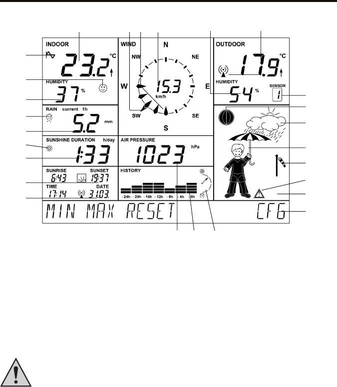
b) Operation
Since all relevant data appear simultaneously on the display, the operation merely involves selecting additional
sensors or additional weather data by lightly touching the corresponding display fields.
The display is divided into the display section and the menu line. During normal operation (main menu displayed)
the menu line reads the followings text fields:
MIN MAX RESET CFG MIN MAX RESET CFG
MIN MAX RESET CFG MIN MAX RESET CFG
MIN MAX RESET CFG
XX
XX
X Touching the display
Lightly touch the corresponding segments of the display field (upper part of the display) to access the following
functions:
INDOORSwitching between temperature and dewpoint display ("DEWPOINT")
OUTDOORSwitching between temperature, dewpoint and windchill display.
HUMIDITYNo function
SENSORSwitching between the external sensors:
Display “1” to “8”: ASH550, ASH550I, S550IA
No display: combination sensor
RAINswitching between the total rain quantity since the last reset (“total”), current hour
(“current 1h”), last hour (“1h”), current day (“current 24h”) and last day (“24h”).
Acquisition of the hour: at xx:30 hours; day: at 7:30 am
SUNSHINE DURATIONSwitching between sunshine duration of the present day (“h/day”) and total sunshine
duration since last reset (“h”)
TIME/DATENo function
WINDSwitching the numerical display between wind speed in km/h, m/s, mph and wind
direction in degrees.
AIR PRESSURESwitching the barometric pressure display between the local measure pressure (“abso-
lute”) and the pressure calculated for sea level (“relative”)
HISTORYSwitching the history display of the last 24 hours between air pressure, indoor
temperature and outdoor temperature (of the displayed sensor)
Weather symbol fieldNo function
84
XX
XX
X Functions of the main menu
MINDisplaying the minimum values
Touch the "MIN" field to show the minimum values of the corresponding data on the display field. Touch
the corresponding field (temperature, air pressure etc.) to show the associated time stamp (date, time)
right in the menu line when the extreme value occurred.
Touch again "MIN" to return to the main menu.
MAXDisplaying the maximum values
Touch the "MAX" field to show the maximum values of the corresponding data on the display field. Touch
the corresponding field (temperature, air pressure etc.) to show the associated time stamp (date, time)
right in the menu line when the extreme value occurred.
Touch again "MAX" to return to the main menu.
RESETResetting certain values
This menu has three submenus for resetting the accumulated sunshine duration (SUN), the amount of
rainfall (RAIN) or the MIN-MAX memory (MIN-MAX).
Apply the "RESET" field. The RESET menu appears:
RESET RAIN OK RESET RAIN OK
RESET RAIN OK RESET RAIN OK
RESET RAIN OK
Touch the "RESET" field repeatedly to select the desired option on the left and then apply "OK". The
selected data are now deleted and the main menu is displayed again.
If you do not wish to delete data, wait until the main menu reappears. The data is then not deleted.
CFGOpening the configuration menu
This menu allows you to enter e.g. the time and date, register sensors and many more settings which
will be explained in the following chapter.
85
c) Configuration
The weather station is operational immediately after it is taken into operation; additional settings of the basic functions
are not necessary (except moon phase, sunset and sunrise indicator, date, clock, min-max display).
But one additional configuration is necessary to use the additional and time-related functions.
•Touch "CFG" to open the configuration menu.
MIN MAX RESET CFG MIN MAX RESET CFG
MIN MAX RESET CFG MIN MAX RESET CFG
MIN MAX RESET CFG
•Touch "NEXT" repeatedly to go to the corresponding next main menu item of the configuration menu. A menu
overview in the Appendix shows how to quickly access individual menus.
XX
XX
X 1. "SENSOR" menu, registering or deleting sensors
See chapter 11 a).
XX
XX
X 2. "TIME/DATE" menu, setting the time and date
This setting is only required if no DCF synchronisation has taken place.
•Select the "TIME/DATE" menu:
NEXT TIME/DATE ENTER NEXT TIME/DATE ENTER
NEXT TIME/DATE ENTER NEXT TIME/DATE ENTER
NEXT TIME/DATE ENTER
•Touch "ENTER" and you will see:
TIME 24H TIME 24H
TIME 24H TIME 24H
TIME 24H
•Touch the "24H" field to select either 12h or 24h time display.
•Touch "TIME" and you will see:
YEAR + 2006 - YEAR + 2006 -
YEAR + 2006 - YEAR + 2006 -
YEAR + 2006 -
•Touch "+" or "-" to set the year.
•Touch "YEAR" and you will see:
MONTH + 07 - MONTH + 07 -
MONTH + 07 - MONTH + 07 -
MONTH + 07 -
•Touch "+" or "-" to set the month.
•Touch "MONTH" and you will see:
DAY + 01 - DAY + 01 -
DAY + 01 - DAY + 01 -
DAY + 01 -
86
•Touch "+" or "-" to set the day date.
•Touch "DAY" and you will see:
WEEKDAY + MON - WEEKDAY + MON -
WEEKDAY + MON - WEEKDAY + MON -
WEEKDAY + MON -
•Touch "+" or "-" to set the weekday.
•Touch "WEEKDAY" and you will see:
HOUR + 01 - HOUR + 01 -
HOUR + 01 - HOUR + 01 -
HOUR + 01 -
•Touch "+" or "-" to set the hour.
•Touch "HOUR" and you will see:
MINUTE + 01 - MINUTE + 01 -
MINUTE + 01 - MINUTE + 01 -
MINUTE + 01 -
•Touch "+" or "-" to set the minute.
•Wait a few seconds and the display shows the time and date, sunrise and sunset time for the factory setting (52.5/
13.4°, Berlin) and the current moon phase.
XX
XX
X 3. "UNITS" menu, setting the display units
•Select the "UNITS" menu:
NEXT UNITS ENTER NEXT UNITS ENTER
NEXT UNITS ENTER NEXT UNITS ENTER
NEXT UNITS ENTER
•Touch "ENTER" and you will see:
TEMPERATURE DEG C TEMPERATURE DEG C
TEMPERATURE DEG C TEMPERATURE DEG C
TEMPERATURE DEG C
•Touch "DEG" to switch the display between degrees Celsius (C) and degrees Fahrenheit (F).
•Touch "TEMPERATURE" and you will see:
PRESSURE HPA PRESSURE HPA
PRESSURE HPA PRESSURE HPA
PRESSURE HPA
•Touch "HPA" to switch the air pressure display between hPa (HPA), mmHg (MMHG) und inHg (INHG)
•Touch "PRESSURE" and you will see:
RAIN MM RAIN MM
RAIN MM RAIN MM
RAIN MM
•Touch "MM" to switch between rain quantity display in mm (MM), inches (INCH) or l/m² (L/M2).
•Wait a few seconds and the data are displayed in the selected units.
87
XX
XX
X 4. "POSITION" menu, setting the position
The position data of the installation site of the weather station is required for calculating the sunrise and sunset times.
You can enter between –60.0° and +60.0° latitude.
There are different ways to determine your position:
•The Appendix contains a list with the coordinates of numerous German cities. You can select a city in your vicinity
and enter its coordinates.
•If you have GPS, e.g. in your car or a mobile unit, you can take over the coordinates indicated there and so obtain
the exact position.
•Accurate coordinates can also be found on the internet. There are various sites about navigation.
After you have determined your position coordinates, enter the data into the weather station as follows:
•Select the "POSITION" menu:
NEXT POSITION ENTER NEXT POSITION ENTER
NEXT POSITION ENTER NEXT POSITION ENTER
NEXT POSITION ENTER
•Touch "ENTER" and you will see:
LATITUDE + 52.4 - LATITUDE + 52.4 -
LATITUDE + 52.4 - LATITUDE + 52.4 -
LATITUDE + 52.4 -
•Touch "+" or "-" to set the latitude.
•Touch "LATITUDE" and you will see:
LONGITUDE + 007.8 - LONGITUDE + 007.8 -
LONGITUDE + 007.8 - LONGITUDE + 007.8 -
LONGITUDE + 007.8 -
•Touch "+" or "-" to set the longitude.
•Wait a few seconds and the corrected data for sunrise and sunset are displayed.
Please bear in mind that the sunrise and sunset times are really only accurate at the sea or in a
completely plane landscape.
Mountains, high woods etc. can considerably shorten the real days.
Even if the location is ideal, it is possible that the data differ by a few minutes, since an approximation
formula is used to calculate these times.
88
XX
XX
X 5. "TIMEZONE" menu, setting the time zone
The time zone is required for calculating the sunrise and sunset times. You must enter the present offset to the UTC
(Coordinated Universal Time) here.
For Germany the following values apply:
Daylight saving time:+2 hours
Winter time:+1 hour
Proceed as follows:
•Select the "TIMEZONE" menu:
NEXT TIMEZONE ENTER NEXT TIMEZONE ENTER
NEXT TIMEZONE ENTER NEXT TIMEZONE ENTER
NEXT TIMEZONE ENTER
•Touch "ENTER" and you will see:
TIMEZONE + 01 - TIMEZONE + 01 -
TIMEZONE + 01 - TIMEZONE + 01 -
TIMEZONE + 01 -
•Touch "+" or "-" to set the time zone.
•Wait a few seconds and the corrected data for sunrise and sunset are displayed.
89
XX
XX
X 6. "LIGHTING" menu, setting the background lighting
This menu allows you to set the switch-on time for the background lighting which switches on automatically upon
touching the screen and switches off again after a settable time. You can set either OFF (lighting always off), times
between 5 seconds and 10 minutes and permanent light (ON). And you can specify times during which the lighting
is to be permanently activated.
You can also activate/deactivate the automatic adjustment to the ambient lighting conditions so that the display can
be read optimally under nearly any light conditions.
The background lighting can only be used if the weather station is mains operated (not when it is battery-
powered!).
•Select the "LIGHTING" menu:
NEXT LIGHTING ENTER NEXT LIGHTING ENTER
NEXT LIGHTING ENTER NEXT LIGHTING ENTER
NEXT LIGHTING ENTER
•Touch "ENTER" and you will see:
LIGHTING + 10 SEC - LIGHTING + 10 SEC -
LIGHTING + 10 SEC - LIGHTING + 10 SEC -
LIGHTING + 10 SEC -
•Touch "+" or "-" to set the switch-on time.
•Touch "LIGHTING" and you will see:
BRIGHT CTRL ON BRIGHT CTRL ON
BRIGHT CTRL ON BRIGHT CTRL ON
BRIGHT CTRL ON
•Touch "ON" to switch the display between automatic brightness control active (ON) or deactivated (OFF).
•Touch "BRIGHT CTRL" and you will see:
BEGIN + 16.00 - BEGIN + 16.00 -
BEGIN + 16.00 - BEGIN + 16.00 -
BEGIN + 16.00 -
•Touch "+" or "-" to set the switch-on time for the lighting (permanent lighting).
•Touch "BEGIN" and you will see:
END + 23.45 - END + 23.45 -
END + 23.45 - END + 23.45 -
END + 23.45 -
•Touch "+" or "-" to set the switch-off time for the lighting (permanent lighting).
•Wait a few seconds and the station will return to normal mode and your settings will be activated.
90
XX
XX
X 7. "SYSTEM" menu, system settings
This menu allows you to make settings for the automatic daylight-saving time/winter time changeover ("DST", see
also Appendix), activate the acoustic key acknowledge signal ("BEEP"), activate the DCF radio clock ("DCF"), specify
the data acquisition interval of the data logger ("INTERVAL"), enter the altitude ("ALTITUDE") and calibrate the rain
sensor ("RAIN CAL") and configure the brightness threshold for the sunshine duration ("SUN CAL").
Z "BEEP": Activate / deactivate the acoustic key acknowledge signal
•Select the "SYSTEM" menu:
NEXT SYSTEM ENTER NEXT SYSTEM ENTER
NEXT SYSTEM ENTER NEXT SYSTEM ENTER
NEXT SYSTEM ENTER
•Touch "ENTER" and you will see:
BEEP ON BEEP ON
BEEP ON BEEP ON
BEEP ON
•Touch "ON" to switch the key acknowledge beep ON or OFF.
Z "DCF": Activating / deactivating DCF reception
•Select the "SYSTEM" menu and (via "BEEP") the option "DCF":
DCF ON DCF ON
DCF ON DCF ON
DCF ON
•Touch "ON" to switch the DCF reception ON or OFF.
Z "DST": Activating/deactivating the daylight-saving time/winter time changeover
•Select the "SYSTEM" menu and (via "BEEP" and "DCF") the option "DST":
DST ON DST ON
DST ON DST ON
DST ON
•Touch "ON" to switch the automatic daylight saving time changeover ON or OFF.
Z "INTERVAL": Setting the data logger acquisition interval
The data logger acquisition interval specifies the intervals in which the integrated data logger records the datasets.
The shorter you select the intervals, the shorter are the recording time but the recording becomes more detailed. If
the intervals are longer, the possible recording time increases but the resolution of the weather data decreases.
The acquisition interval can also be set from the computer.
•Select the "SYSTEM" menu and here (via "BEEP", "DCF" and "DST") the option "INTERVAL":
INTERVALL + 05 - INTERVALL + 05 -
INTERVALL + 05 - INTERVALL + 05 -
INTERVALL + 05 -
91
•Touch "+" or "-" to set the interval time (OFF = data logger deactivated, 5 minutes to 60 minutes). Below you will
find some examples of how the interval time and the recording time relate:
Interval timeMax. recording time
5 minutes10.4 days (250 hours)
10 minutes20.8 days (500 hours)
30 minutes62.5 days (1500 hours)
60 minutes125 days (3000 hours)
Z "ALTITUDE": Setting the altitude
The altitude is needed for calculating the relative air pressure related to sea level compared to the absolute air
pressure at your location. This relative value is an important reference quantity to be able to correctly interpret
weather forecasts referring to the relative air pressure.
•Select the "SYSTEM" menu and here (via "BEEP", "DCF", "DST" and "INTERVAL") the option "ALTITUDE":
ALTITUDE ENTER ALTITUDE ENTER
ALTITUDE ENTER ALTITUDE ENTER
ALTITUDE ENTER
•Touch "ENTER" and you will see:
ALTITUDE + 0000 - ALTITUDE + 0000 -
ALTITUDE + 0000 - ALTITUDE + 0000 -
ALTITUDE + 0000 -
•Touch "+" or "-" to set the geographic altitude of your location above sea level in meters.
•Wait a few seconds and the corrected data for the relative air pressure are displayed. The value can also be
entered via the supplied software.
Z "RAIN CAL": Entering the calibration value for the rain collector
The rain measuring gauge is extremely accurate upon delivery; therefore it is normally not necessary to calibrate it.
The calibration value must first be determined during normal mode as described in the chapter “Calibration of the
rain collector”.
•Select the "SYSTEM" menu and here (via "BEEP", "DCF", "DST", "INTERVAL" and "ALTITUDE") the option
"RAIN CAL":
RAIN CAL ENTER RAIN CAL ENTER
RAIN CAL ENTER RAIN CAL ENTER
RAIN CAL ENTER
•Touch "ENTER" and you will see:
RAIN CAL + 295 - RAIN CAL + 295 -
RAIN CAL + 295 - RAIN CAL + 295 -
RAIN CAL + 295 -
•Touch "+" or "-" to set the previously calculated value.
•Wait a few seconds until the station returns to the normal display. The value can also be entered via the supplied
software.
92
Z "SUN CAL": Configuring the brightness threshold for sunshine duration
The WS550 weather station measures the sunshine duration with its combination sensor. The threshold value is set
at the display console and is then transmitted to the combination sensor. The sensor then evaluates the data:
Measured brightness greater than threshold¨sun is shining
Measured brightness smaller than threshold¨sun is not shining
The brightness threshold can be set individually by the user to adjust the sensor to the local conditions. The threshold
value should be defined when the sun begins or stops to shine to make conclusions from the present brightness value
to the threshold.
•Select the "SYSTEM" menu and here (via "BEEP", "DCF", "DST", "INTERVAL", "ALTITUDE" and "RAIN CAL")
the option "SUN CAL":
SUN CAL ENTER SUN CAL ENTER
SUN CAL ENTER SUN CAL ENTER
SUN CAL ENTER
•Touch "ENTER" and you will see:
SUN CAL 131 + 085 - SUN CAL 131 + 085 -
SUN CAL 131 + 085 - SUN CAL 131 + 085 -
SUN CAL 131 + 085 -
The medium display range (131 in the above example) shows the present brightness value.
The direct conversion into lux is not possible.
The right display area (085 in the above example) shows the adjusted threshold value.
•Touch "+" or "-" to set the threshold value. The setting range is from 0 to 255.
•Wait a few seconds until the station resumes normal mode.
93
XX
XX
X 8. "CLEANING" menu, cleaning mode
A cleaning mode is available in which all touch fields are locked for 20 seconds so that no functions are triggered when
wiping the display.
The display becomes dirty during use and needs to be wiped clean from time to time using a clean, soft and dry linen.
A glasses cleaning cloth is well suited for this purpose. Do not use cleaning agents which can destroy
the touch-sensitive display!
Do not press too much on the display when wiping it clean.
•Select the "CLEANING" menu:
NEXT CLEANING ENTER NEXT CLEANING ENTER
NEXT CLEANING ENTER NEXT CLEANING ENTER
NEXT CLEANING ENTER
•Touch "ENTER" and you will see:
CLEANING START CLEANING START
CLEANING START CLEANING START
CLEANING START
•Touch "START" and you will see:
CLEANING WAIT CLEANING WAIT
CLEANING WAIT CLEANING WAIT
CLEANING WAIT
•Now you can clean the display. The tactile sensors in the display are deactivated. After 20 seconds the normal
display reappears and the tactile sensors are reactivated.
If you have not yet finished cleaning the display, you can start the cleaning mode again.
94
XX
XX
X 9. "LIVE MODE" menu, starting the weather ticker
The live mode is started by applying an additional touch field which prompts the combination sensor to send its data
in 2-second intervals during a period of 20 seconds. This allows you to track e.g. the current weather conditions e.g.
the wind direction and the wind speed in real-time for a period of 20 seconds.
In LIVE MODE the combination sensor consumes more power because it switches to reception more
frequently. This reduces the battery lifetime.
You can therefore set a time limit for this mode in the LIVE MODE menu. During that time, the additional touch field
REQ will appear in the main menu line which triggers the live weather ticker.
•Select the "LIVE MODE" menu:
NEXT LIVE MODE ENTER NEXT LIVE MODE ENTER
NEXT LIVE MODE ENTER NEXT LIVE MODE ENTER
NEXT LIVE MODE ENTER
•Touch "ENTER" and you will see:
BEGIN + 16.00 - BEGIN + 16.00 -
BEGIN + 16.00 - BEGIN + 16.00 -
BEGIN + 16.00 -
•Touch "+" or "-" to set the switch-on time for the LIVE MODE.
•Touch "BEGIN" and you will see:
END + 23.45 - END + 23.45 -
END + 23.45 - END + 23.45 -
END + 23.45 -
•Touch "+" or "-" to set the switch-off time for the LIVE MODE.
•Wait a few seconds and the station will return to normal mode and your settings will be activated.
•The following message appears in the menu line while the data are transmitted to the combination sensor:
WAIT FOR TRANSMISSION WAIT FOR TRANSMISSION
WAIT FOR TRANSMISSION WAIT FOR TRANSMISSION
WAIT FOR TRANSMISSION
While this message is displayed, the weather station can not be operated.
•The additional touch field "REQ" is displayed on the menu when the LIVE MODE is activated for requesting the
data:
MIN MAX RESET REQ CFG MIN MAX RESET REQ CFG
MIN MAX RESET REQ CFG MIN MAX RESET REQ CFG
MIN MAX RESET REQ CFG
95
d) Additional functions and displays
XX
XX
X 1. Moon phase indicator
The moon phase indicator uses the following symbols:
Full moonWaningNew moonWaxing
XX
XX
X 2. Animated weather display
An animated figure shows several weather factors at the same time:
Outdoor temperature (combination sensor only)
The way the figure is dressed depends on the outdoor temperature at the combination sensor.
Rain
If the weather forecast has predicted rainy weather, the figure will carry a closed umbrella. When it has started
to rain, the figure carries an open umbrella.
Wind speed
When wind speeds exceed 20 km/h (moderate wind), the little man’s hair is blowing in the wind. If the temperature
is simultaneously below 14°C, the man’s scarf will also be blown by the wind.
XX
XX
X 3. Weather forecast
The weather forecast symbols predict the following weather:
Clouds with rain¨Rainy
Clouds¨ Overcast
Clouds with sun¨Fair
Sun¨ Sunny
XX
XX
X 4. Windsock display
The windsock symbol in the forecast display field shows at a glance whether the wind is presently blowing lightly,
moderately or heavily.
Windsock is slack¨light wind (<10 km/h)
Windsock half lifted¨moderate wind (10...20 km/h)
Windsock vertical¨strong wind (>20 km/h)
96
XX
XX
X 5. Onsetting rain display
The onset of rain is reported to the console with the next wireless data transmission and symbolised by a rain cloud
in the "RAIN" field and by the open umbrella of the little man.
XX
XX
X 6. Comfort indicator
The comfort indicator (
☺
) reflects the room climate (relationship between temperature and air humidity). You
can find a value table for the display ranges in the Appendix.
XX
XX
X 7. History
The bar chart shows the development of the barometric pressure or of the outdoor and indoor temperature over the
last 24 hours. The individual bars do not represent an absolute value here; rather they show the difference to the
current measured value (0h bar). This point of reference is always located in the center (4 bars) to see at a glance
what the trend is.
XX
XX
X 8. Data memory
The following message appears in the menu line when the data memory is nearly full:
MEMORY ALMOST FULL OK MEMORY ALMOST FULL OK
MEMORY ALMOST FULL OK MEMORY ALMOST FULL OK
MEMORY ALMOST FULL OK
Touch OK to confirm the message and download the collected data to your computer.
XX
XX
X 9. Data transmission to the combination sensor ("WAIT FOR TRANSMISSION")
If the menu line reads "WAIT FOR TRANSMISSION", the weather station is currently busy sending data to the
combination sensor, e.g. when activating the Live Mode or the configuration data of the sunshine duration.
This process may take up to several minutes. During this time the weather station can not be operated.
XX
XX
X 10. Temperature trend display
An arrow to the right of the temperature displays in the "INDOOR" and "OUTDOOR" display fields indicates the
temperature trend during the last transmission interval. An increase in temperature is indicated by an arrow pointing
upwards and a decrease by a downward pointing arrow.
97
XX
XX
X 11. Sensor status display
The sensor status is indicated by a small radio tower symbol in the "OUTDOOR" display field.
Radio tower appears constantly¨Data from the sensor are received correctly.
Radio tower is blinking¨No data have been received from the sensor for 40 minutes.
No radio tower symbol¨The sensor is not there or it is permanently faulted or defective.
XX
XX
X 12. DCF77 time signal
•Directly after it has been switched on, the weather station makes an attempt to receive the DCF77 time signal in
order to set its clock automatically.
•If the weather station receives the time signal, time and date will be updated automatically and a small radio tower
icon appears between them.
•Every day at 4:00 am the weather station starts a synchronisation attempt with the DCF77 transmitter.
•If no DCF77 signal is received, the internal clock operates as a quartz clock.
•DCF77 reception can be deactivated if required (see menu "SYSTEM/DCF").
XX
XX
X 13. Warning against heavy weather
A danger sign will appear in the weather forecast display field if the barometric pressure drops sharply within a short
time. This could be a sign of a storm or thunderstorm approaching.
XX
XX
X 14. Low-temperature alert
A snowflake will appear in the weather forecast display field if the measured temperature at the combination sensor
falls below +4°C .
98
11. Battery replacement
a) Display console
If the empty battery symbol ( ) appears, all batteries have to be replaced by new ones as described in chapter
9 a) or 9 c).
Replace always all four batteries and insert only high-quality alkaline batteries. The weather station
should be connected to the power supply when changing batteries to avoid data loss.
Please note:
If no power adapter is connected, the data memory will be cleared when changing the batteries and all
measured values will be deleted.
b) Wireless sensors
The batteries in these sensors have a life span of up to 2 years (alkaline batteries). They must be changed if a battery
empty symbol ( ) appears in the OUTDOOR sensor field when selecting the corresponding sensor.
The batteries of the combination sensor are changed as described in chapter 9 g). For the other sensors, please refer
to their manuals.
99
12. Troubleshooting notes
Possible malfunctions can hinder the correct display of the measured values:
•No signal received
¨The distance between transmitter and receiver is too great or too small (< 1 m). Reduce or increase the
distance between transmitter and receiver.
¨Strongly shielding materials are between the transmitter and the receiver (thick walls, reinforced concrete
etc.). Select a different location for transmitter or receiver. See also the chapter “Transmission range” in this
context.
¨The batteries of the sensors are empty, change the batteries.
¨The transmitter is superimposed by interfering transmitters (radio equipment, wireless headphones or
speakers). Eliminate the source of the interference or select a different location for transmitter and receiver.
If wireless headphones, wireless baby monitors or similar devices are operated at 868 MHz, they are usually
switched on for a limited time only, interferences will therefore occur only occasionally.
It may be possible to operate these devices on a different frequency so that they no longer interfere with the
weather station.
•The wireless sensor interferes with other devices in the 868 MHz range
¨The transmissions of the wireless outdoor sensor can temporarily (every 2 to 3 minutes for approx. 100 ms)
interfere with other device operating on the same channel.
In some wireless headphones, for instance, this becomes evident as a short noise.
Select a different transmission/reception frequency for the device you are using (e.g. wireless headphones)
if possible.
Additional notes for startup and troubleshooting
Try to turn the weather station a bit, place it in some distance from electrical motors, electrical machines television
sets, computer screens and large metal surfaces.
For an easier start you can also set up the sensor near the display console (at least 1 m distance). Here you can first
check that the sensor correctly sends its data and thus the function of the weather station.
The sensor must be properly registered at the weather station or their data will not be displayed.
100
13. Transmission range
The transmission range in the open field, i.e. there is visual contact between transmitter and receiver, is 300 m under
optimal conditions. Walls and even reinforced steel structures can be penetrated but this reduces the range
accordingly.
A reduced transmission range can be due to the following factors:
•High frequency interferences of all sorts
•Any kind of housing or vegetation
•The distance of the transmitter or receiver to conducting surfaces or objects (also the human body or the ground)
influences the emission characteristics and thus the range.
•Broadband interferences in urban areas can reach levels that decrease the signal—to-noise ratio over the entire
frequency band thus reducing the range.
•Devices with neighbouring operation frequencies can equally influence the receiver.
•Poorly screened or openly operated computers can emit into the receiver and reduce the range.
Since local conditions vary from site to site, a definite range cannot be guaranteed.
However, normally in a detached house trouble-free operation is possible. When the base station
doesn’t receive any data from one or several sensors (despite new batteries), reduce the distance
between the outdoor sensor(s) and base station, change the installation site.
101
14. Maintenance and care
a) General information
Maintenance or repairs may only be carried out by qualified persons or a specialist workshop.
Improper work invalidates not only the guarantee/warrantee but also the license (CE). It also involves
the risk of a fatal electric shock.
This product does not contain any serviceable parts. Therefore, do not open it (except for those operations described
in this manual e.g. assembly, inserting or changing the batteries etc.).
Regularly check the technical safety of the product e.g. for damage of the housing.
If there is any reason to believe that safe operation has become impossible, put the device out of operation and secure
it against any unintended operation. Remove the batteries, disconnect the weather station from the mains adapter
and unplug the mains adapter from the mains socket.
It can be assumed that safe operation is no longer possible if
•the device shows visible damages,
•the device is no longer functional and
•after it was stored under unfavourable conditions for a long period of time or
•after it was exposed to extraordinary stress caused by transport.
b) Cleaning the display console
Before cleaning the display, activate the Cleaning Mode at the display console as described in chapter 11 c). When
you clean the display without using the cleaning mode, you can inadvertently trigger functions which can lead to
undesired results.
To clean the display, use only a soft, clean and dry cloth. A glasses cleaning cloth is well suited for this
purpose.
Do not use rough cloths; never use liquid cleansers! This can be aggressive on the touch-sensitive
surface of the display.
Dust can be removed using a clean, soft brush and a vacuum cleaner.
Do not press too much on the display when wiping it clean.
102
c) Cleaning the outdoor sensors
Dirt on the outdoor sensors can be removed with a damp cloth.
Never use aggressive cleansing agents or other chemical solvents since they can damage the surface
of the housing or even impair operation.
Do not hose down the outdoor sensors because the outdoor sensors are only protected against rain
that comes from above and not against a jet of water from the side or from below.
d) Cleaning the rain collector
Depending on the installation site, it is possible that the wind carries dirt particles, sand, small branches etc. into the
collection funnel of the rain collector. Bigger parts could block the funnel.
You should therefore check the collection funnel regularly. Remove any leaves or other dirt you find there.
A tipping bucket is located inside the rain collector. Greater amounts of sand or dust that accumulate here can corrupt
the measurement result.
Therefore, you should disassemble the rain collector from time to time and clean the tipping bucket. We
recommend to do this at least once each year.
To disassemble or re-assemble the rain collector, proceed as follows:
1.Open the lower part of the rain collector by turning it counter clockwise
by approx. 1 cm until you can slide it down at the metal tube.
Remove next the collection funnel by turning it slightly clockwise and lift
it off.
Bear in mind the orientation of the latch lugs.
2.You can now take out the rain collector (the plastic part with the two brass pins and the cable).
Keep in mind the orientation: the connecting cable of the rain collector is located on one side.
3.Take out the tipping bucket.
Keep in mind the orientation: there is a small magnet on one side of the tipping bucket.
¨
¨
¨
¨
1
2
34
103
4.Now clean the components of the rain collector. Clean also the drain hole in the plastic lower part of the rain
collector that you slid down the metal tube.
5.To reassemble the rain collector, insert first the tipping
bucket into its holder.
The magnet of the tipping bucket must be on the
side that faces the cable.
The two lower trapezoid pins must be properly
inserted into the bottom section of the holder.
In that way the tipping bucket will move smoothly.
6.Insert the rain collector into its mount. It will automatically
hold the tipping bucket as well.
Only one orientation is correct.
The cable of the rain collector and the magnet of
the tipping bucket must be on the same side.
The plastic lug on the other side must be properly
inserted into the holder!
7.Place the collection funnel back on the sensor carrier and turn it counter
clockwise to lock it.
Close the bottom part of the rain collector.
¨
¨
¨
¨
4
3
2
1
104
e) Calibrating the rain collector
The rainfall measuring gauge is extremely accurate upon delivery; therefore it is normally not necessary
to calibrate it.
A calibration is only necessary if utmost accuracy is required.
The calibration process is rather long (at least 10 minutes) and must be carried out with extreme
diligence and care or the accuracy will be poorer than before.
Before starting the calibration of the rain collector, reset the rain quantity at the display console to zero
(total rain display reads zero) in normal display mode.
And the unit for the rain quantity must be set to “mm” or “l/m²” for the calibration. Set the display unit
correctly.
Make also sure that the rain collector is clean (collection funnel, drain hole, tipping bucket) and that the
tipping bucket is dry.
To accurately calibrate the unit, then proceed as follows:
1. Pour in 100 ml of water very slowly into the collection funnel of the rain collector over a period of 10 minutes.
Caution!
If you pour in the water too quickly, the measuring result will become inaccurate. Pour in the water so
slowly that the water is never standing in the funnel.
Please remember that even in heavy rain only a few raindrops will fall into the opening of the rain
collector.
2. The total quantity should now be 6.5 l/m².
3. If a different value is displayed, the so-called tipping value must be recalculated as follows:
6.5 x present tipping value
New tipping value =
Actual value (display after filling in the water)
4.Now enter the new tipping value in the configuration menu (RAIN CAL system menu). It is indicated in ml/tipping
scoop.
The ex-factory setting is 295 ml/tipping scoop.
105
15. Handling
Take note of all the safety instructions in these operating instructions!
a) General information
The product must not be opened or disassembled (except those operations described in this manual for inserting
batteries, assembling or cleaning the rain collector).
Even a fall from a low height can damage the product.
b) Display console
•Avoid the following adverse environmental conditions when setting up and operating the display console:
-moistness or too high air humidity
-extreme cold or hot temperatures
-direct sunlight
-dust or flammable gases, fumes or solvents
-strong vibrations
-strong magnetic fields such as exist near machines or loudspeakers
•Never use the display console and the mains adapter immediately after it has been brought from a cold room into
a warm room. Condensation water that forms might destroy the product.
The mains adapter also involves the risk of an electric shock!
Wait until the display console and the mains adapter have reached room temperature. This can take several hours.
•The installation site should be chosen so that the display console has a firm stand and cannot fall down. Because
of the heavy weight there is a risk of injuries.
Select an even and sufficiently large surface for setting up the display console.
•Valuable or scratch sensitive furniture surfaces should be protected from damage with suitable covers before
placing the display console on them.
106
c) Combination sensor
The supplied combination sensor can be used in exposed outdoor areas.
But do not hose down the combination sensor with a garden hose or similar equipment.
Select an installation site where the sensor can not be knocked over by children. Do not erect the combination sensor
near vehicles, glass doors or windows!
16. Disposal
a) General information
At the end of its useful life dispose of the product according to the relevant statutory regulations!
b) Batteries and rechargeable batteries
The end user is legally obliged (battery regulation) to return used batteries and rechargeable batteries. Do not throw
used batteries into the household waste!
Batteries/storage batteries containing harmful substances are marked with the following symbols which
point out that the disposal via the household rubbish is prohibited. The designations for the respective
hazardous heavy metals are: Cd=cadmium, Hg=mercury, Pb=lead (name on battery/rechargeable
battery, e.g. under the rubbish bin icons on the left).
You can return your exhausted batteries/rechargeable batteries free of charge to any authorized
disposal station in your area, in our stores or in any other store where batteries/rechargeable batteries
are sold.
Thus, you comply with your legal obligations and make your contribution to environmental protection.
107
17. Connection to the computer
The WS550 can be connected to a computer via USB (Windows 2000, Windows XP or higher).
The measured values can then be downloaded to the computer and the data can be analysed.
Please observe the software manual.
The “WeatherPro Edition 2007” software has the following system requirements:
•Windows 2000/XP operating system
•Min. 1GHz frequency
•Min. 256 MB RAM
•Required hard disk space for the program: approx. 150 MB
•Required space for the database: approx. 100 MB
•The hard disk drive must be formatted with the NTFS file system (FAT32 is not possible for the database)
•The Windows installer service must be installed (standard Windows options).
•One free USB port
Proceed as follows:
•Connect the weather station via the USB cable to a free USB port of the computer.
•The computer will detect the new USB device after a short time and ask for a driver. The installation wizard opens.
•Insert the supplied CD into the correct drive of your computer and wait until the Welcome screen appears.
•In the Installation Wizard select the option “Search automatically”.
•Follow the instructions of the Installation Wizard until you have finished installing the drivers.
•Go to the “WeatherPro Edition 2007 Setup” which describes the four setup steps. Begin at step 2.
•Follow the instructions step by step until the installation is finished. Then you can start “WeatherPro Edition 2007”
from the Desktop or the program menu.
•You will find the program description in the help menu at “Manual”.
108
18. Firmware update
A firmware update of the main controller of the WS550 can be performed using the supplied software via the USB
port.
Start the update program in “WeatherPro Edition 2007” (“Options” menu, “Firmware update” menu item) and follow
the instructions by the program.
Note:
If you have started the update process by mistake, you can abort it at any time until step 5.
If the update mode has also been activated at the device according to the instructions of the software,
the weather station must be disconnected from the USB port and the mains socket for a few seconds
and the batteries must be removed. The device function is not affected by this; after restart it will operate
with the firmware version used so far.
109
19. Technical data
Measuring interval of outdoor sensors: ..........................................................................................................2-3 min
Measuring interval of indoor sensor (temperature, air humidity): .................................................................... 3 min
Measuring interval of barometric pressure:.....................................................................................................15 min
Free field range:.......................................................................................................................................max. 300 m
Indoor temperature range: ...................................................................................................................0°C to +60°C
Accuracy:..............................................................................................................................±1°C (+15°C to +40°C)
Outdoor temperature range (combination sensor): ................................................................... -19.9°C to +79.9°C
Accuracy:...........................................................................................................................±0.8°C (+10°C to +40°C)
Measuring range of rel. humidity (indoor/outdoor):....................................................................... 1% rH to 99% rH
Accuracy:................................................................................................................................ ±5% rH (30 to 70% rH)
Rain quantity display: .............................................................................................................................0 to 999 mm
Evaluation interval: ..............................................................................................................last hour: at xx:30 hours
............................................................................................................................................................day: at 7:30 am
Resolution: ............................................................................................................................up to 100 mm: <0.3 mm
Wind speed: ............................................................................................................................................0 – 200 km/h
Resolution: ..........................................................................................................................up to 100 km/h: 0.1 km/h
..............................................................................................................................................above 100 km/h: 1 km/h
Wind direction: ............................................................................................................................................0° to 355°
Libble takes abuse of its services very seriously. We're committed to dealing with such abuse according to the laws in your country of residence. When you submit a report, we'll investigate it and take the appropriate action. We'll get back to you only if we require additional details or have more information to share.
Product:
Forumrules
To achieve meaningful questions, we apply the following rules:
First, read the manual;
Check if your question has been asked previously;
Try to ask your question as clearly as possible;
Did you already try to solve the problem? Please mention this;
Is your problem solved by a visitor then let him/her know in this forum;
To give a response to a question or answer, do not use this form but click on the button 'reply to this question';
Your question will be posted here and emailed to our subscribers. Therefore, avoid filling in personal details.
Register
Register getting emails for Techno line WS 550 at:
new questions and answers
new manuals
You will receive an email to register for one or both of the options.
Get your user manual by e-mail
Enter your email address to receive the manual of Techno line WS 550 in the language / languages: English, German as an attachment in your email.
The manual is 5,66 mb in size.
You will receive the manual in your email within minutes. If you have not received an email, then probably have entered the wrong email address or your mailbox is too full. In addition, it may be that your ISP may have a maximum size for emails to receive.
The manual is sent by email. Check your email
If you have not received an email with the manual within fifteen minutes, it may be that you have a entered a wrong email address or that your ISP has set a maximum size to receive email that is smaller than the size of the manual.
The email address you have provided is not correct.
Please check the email address and correct it.
Your question is posted on this page
Would you like to receive an email when new answers and questions are posted? Please enter your email address.