536253
35
Zoom out
Zoom in
Previous page
1/40
Next page
E EB
RQT5861-B
AV Control Receiver
Operating Instructions
Model No. SA-DA20
SA-DA15
Note:
“EB” on the packaging indicates the United Kingdom.
Before connecting, operating or adjusting this product,
please read these instructions completely.
Please keep this manual for future reference.
SA-DA20 (Black version)
2
RQT5861
Dear customer
Thank you for purchasing this product.
For optimum performance and safety, please read these
instructions carefully.
Supplied accessories
Table of contents
Safety precautions.....................................................................3
Caution for AC Mains Lead
.....................................................4
Control reference guide
...........................................................5
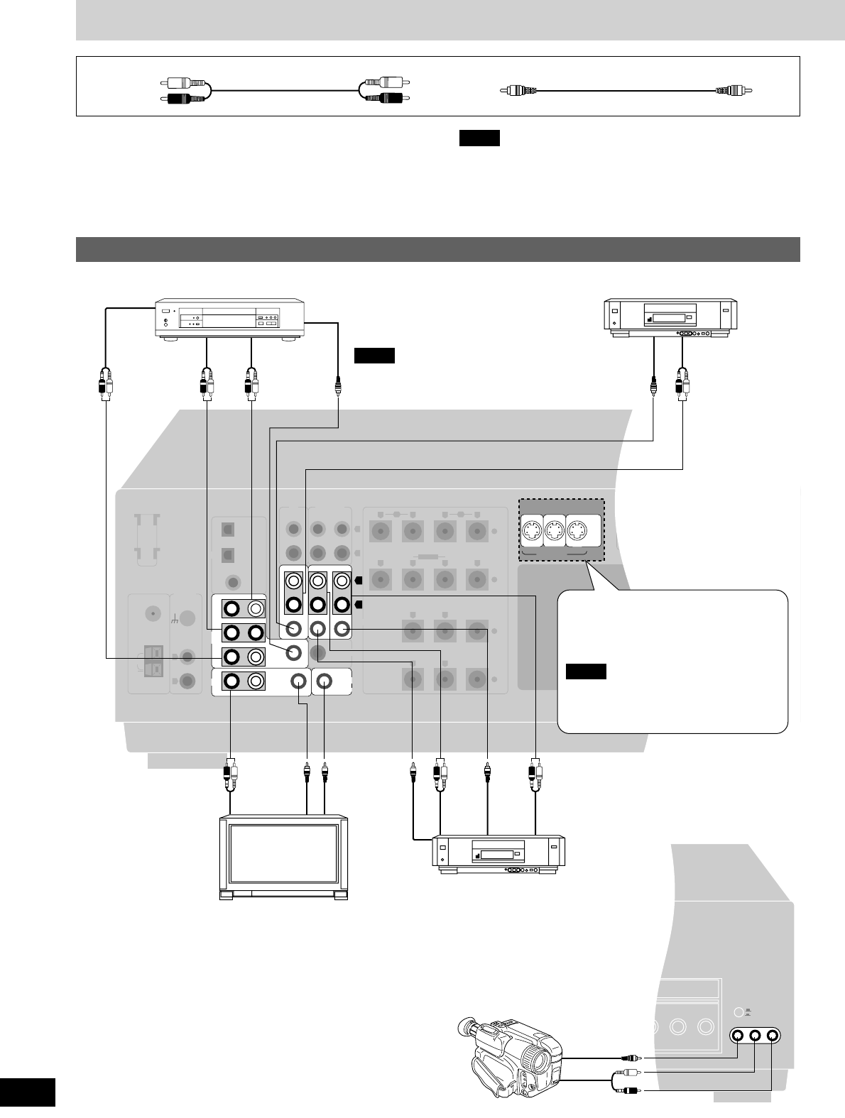
Connections ................................................................................6
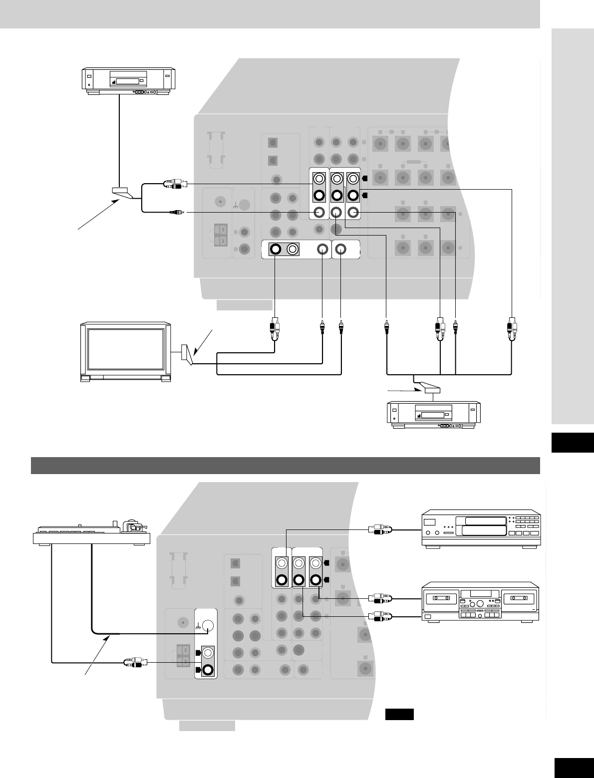
Connecting video equipment.........................................................6
Connecting audio equipment.........................................................7
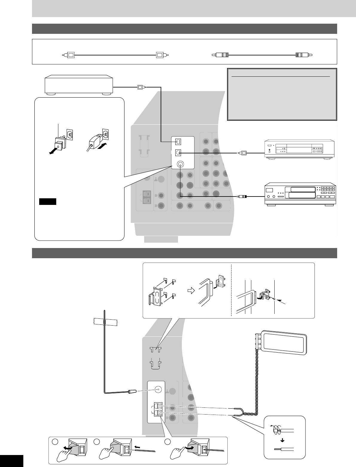
Connecting digital equipment ........................................................8
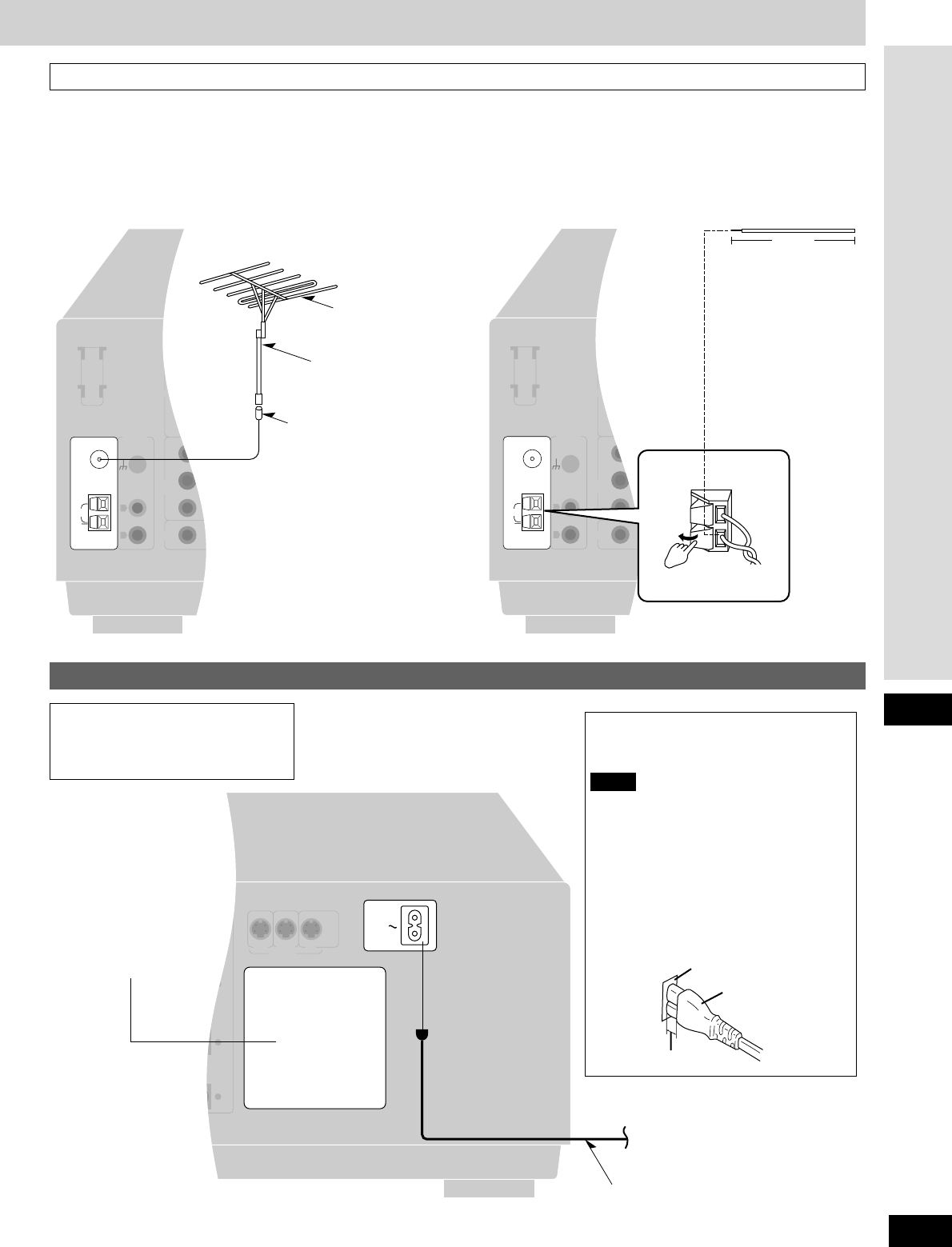
Antenna connections.....................................................................8
Connecting the AC mains lead and other information...................9
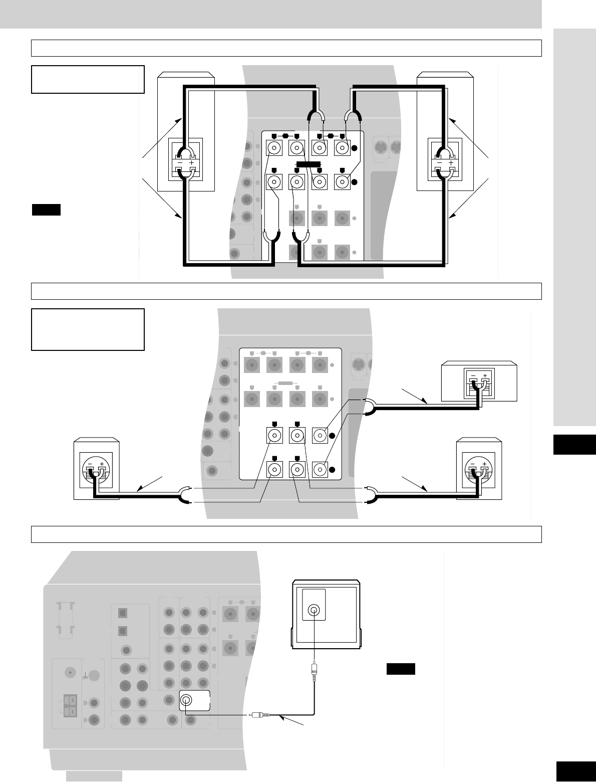
Speaker connections..............................................................10
Placement of speakers................................................................10
Connecting speakers...................................................................10
Customizing your receiver....................................................12
Basic steps ..................................................................................13
Adjusting speaker output level............................................15
DSP sound modes...................................................................16
STEREO mode............................................................................16
SURROUND mode......................................................................16
SFC modes..................................................................................17
Enjoying the sounds...............................................................18
Turning on the VGCA ..................................................................20
Adjusting the tone........................................................................21
Adjusting the balance ..................................................................21
Using the VCR 3 terminals ..........................................................21
Adjusting the subwoofer level......................................................21
The radio.....................................................................................22
Manual tuning..............................................................................22
Preset tuning ...............................................................................23
RDS broadcasts .......................................................................24
To display RDS information.........................................................24
PTY search..................................................................................24
EON tuning..................................................................................25
PTY displays................................................................................25
Other functions.........................................................................26
Muting the volume .......................................................................26
Using the TAPE MONITOR.........................................................26
When using the unit in a darkened room.....................................26
Using headphones.......................................................................26
Making a recording..................................................................27
Recording on a tape or MD deck or VCR....................................27
Remote control.........................................................................28
Batteries ......................................................................................28
Use ..............................................................................................28
Button guide ................................................................................29
Operating the receiver.................................................................30
Operating a DVD/CD player or MD deck.....................................31
Operating a TV ............................................................................32
Operating a VCR .........................................................................33
Operating a cassette deck...........................................................33
To change the remote control codes...........................................34
Timer function...........................................................................36
The HELP function
...................................................................37
The RESET function
................................................................37
Maintenance
..............................................................................37
Troubleshooting guide
...........................................................38
Specifications ...........................................................................39
These operating instructions are applicable to models
SA-DA20 and SA-DA15, however, are intended primarily for
model SA-DA20.
Use the numbers indicated in parentheses when asking for
replacement parts.
Remote control (EUR7502X60)........................................1
Please check and identify the supplied
accessories.
AC mains lead...................................................................1
AM loop antenna set (RSA0012) .....................................1
(AM loop antenna, antenna holder, screw)
FM indoor antenna (RSA0007-L).....................................1
Batteries............................................................................2
Antenna plug (SJP9009) ..................................................1
(Only for the United Kingdom)
For the United Kingdom
(VJA0733)
For Continental Europe
(RJA0019-2K)
3
RQT5861
Before use
Safety precautions
CAUTION
Do not place anything on top of this unit or block the heat
radiation vents in any way. In particular, do not place tape decks
or CD/DVD players on this unit as heat radiated from it can
damage your software.
NO
Enjoying surround sound
Pages
Connect your equipment
6–9
Position and connect the speakers
10, 11
Change the settings
12–14
Adjust speaker output level
15
Sit back and enjoy the experience
18
Placement
Set the unit up on an even surface away from direct sunlight, high
temperatures, high humidity, and excessive vibration. These
conditions can damage the cabinet and other components, thereby
shortening the units service life.
Do not place heavy items on the unit.
Voltage
Do not use high voltage power sources. This can overload the
unit and cause a fire.
Do not use a DC power source. Check the source carefully when
setting the unit up on a ship or other place where DC is used.
AC mains lead protection
Ensure the AC mains lead is connected correctly and not
damaged. Poor connection and lead damage can cause fire or
electric shock. Do not pull, bend, or place heavy items on the lead.
Grasp the plug firmly when unplugging the lead. Pulling the AC
mains lead can cause electric shock.
Do not handle the plug with wet hands. This can cause electric
shock.
Foreign matter
Do not let metal objects fall inside the unit. This can cause
electric shock or malfunction.
Do not let liquids get into the unit. This can cause electric shock
or malfunction. If this occurs, immediately disconnect the unit from
the power supply and contact your dealer.
Do not spray insecticides onto or into the unit. They contain
flammable gases which can ignite if sprayed into the unit.
Service
Do not attempt to repair this unit by yourself. If sound is
interrupted, indicators fail to light, smoke appears, or any other
problem that is not covered in these operating instructions occurs,
disconnect the AC mains lead and contact your dealer or an
authorized service center. Electric shock or damage to the unit can
occur if the unit is repaired, disassembled or reconstructed by
unqualified persons.
Extend operating life by disconnecting the unit from the power
source if it is not to be used for a long time.
4
RQT5861
(For United Kingdom)
(EB area code model only)
For your safety, please read the following text carefully.
This appliance is supplied with a moulded three pin mains plug for
your safety and convenience.
A 5-ampere fuse is fitted in this plug.
Should the fuse need to be replaced please ensure that the
replacement fuse has a rating of 5-ampere and that it is approved
by ASTA or BSI to BS 1362.
Check for the ASTA mark or the BSI mark on the body of
the fuse.
If the plug contains a removable fuse cover you must ensure that it
is refitted when the fuse is replaced.
If you lose the fuse cover the plug must not be used until a
replacement cover is obtained.
A replacement fuse cover can be purchased from your local dealer.
CAUTION!
IF THE FITTED MOULDED PLUG IS UNSUITABLE FOR THE
SOCKET OUTLET IN YOUR HOME THEN THE FUSE
SHOULD BE REMOVED AND THE PLUG CUT OFF AND
DISPOSED OF SAFELY.
THERE IS A DANGER OF SEVERE ELECTRICAL SHOCK IF
THE CUT OFF PLUG IS INSERTED INTO ANY 13-AMPERE
SOCKET.
If a new plug is to be fitted please observe the wiring code as stated
below.
If in any doubt please consult a qualified electrician.
IMPORTANT
The wires in this mains lead are coloured in accordance with the
following code:
Blue: Neutral, Brown: Live.
As these colours may not correspond with the coloured markings
identifying the terminals in your plug, proceed as follows:
The wire which is coloured Blue must be connected to the terminal
which is marked with the letter N or coloured Black or Blue.
The wire which is coloured Brown must be connected to the
terminal which is marked with the letter L or coloured Brown or Red.
WARNING: DO NOT CONNECT EITHER WIRE TO THE EARTH
TERMINAL WHICH IS MARKED WITH THE LETTER E, BY
THE EARTH SYMBOL OR COLOURED GREEN OR
GREEN/YELLOW.
THIS PLUG IS NOT WATERPROOFKEEP DRY.
Before use
Remove the connector cover.
How to replace the fuse
The location of the fuse differ according to the type of AC mains
plug (figures A and B). Confirm the AC mains plug fitted and follow
the instructions below. Illustrations may differ from actual AC mains
plug.
1. Open the fuse cover with a screwdriver.
Figure A
Figure B
Fuse cover
2. Replace the fuse and close or attach the fuse cover.
Figure A
Fuse
(5 ampere)
Figure B
Fuse
(5 ampere)
Caution for AC Mains Lead
Control reference guide
5
RQT5861
Before use
TUNED
STEREO
MONO
LOW IMP
EONPS PTY RT
kHz
MHz
PRO LOGIC
PROGRAM FORMAT
DIGITAL
WAKE
SLEEP
SOUND MODE
STEREO
SURROUND
SFC
LCR
LS S LFE RS
AB
BI-WIRE
M
RDS
SPEAKERS
A B BI-WIRE
VOLUME
MIN MAX
DIGITAL
TUNING MEMORY
DISPLAY MODE
-
PTY SEARCH
WAKE
BAND
FM MODE
EON RDS
DSP SOUND MODE
VGCA
ON
VIA TONE
MIN MAX MIN MAX L R
BALANCETREBLEBASS
VCR 2
VCR 3
VIDEO IN
L AUDIO IN R
TAPE MONITOR DIGITAL INPUT
PHONES
TIMER
1 3 42 5 6 7 8 9 10 11
13 14 15 18 19 20 2221 23 24 25 26 27 2812
BI-AMP
DVD 6CH INPUT
INPUT SELECTOR
VCR 3
29 30 31 32 33 3534 36
3837 39 40 41 42
MODE
TIME
PTY SELECTOR
16 17
PRESET
SPEAKERS
Main unit
Display section
qq
Standby/on switch [8]........................................................(13)
Press to switch the unit from on to standby mode or vice versa.
In standby mode, the unit is still consuming a small amount of
power.
ww
Standby indicator [^]
When the unit is connected to the AC mains supply, this
indicator lights up in standby mode and goes out when the unit
is turned on.
ee
Speaker select buttons
[SPEAKERS, A, B, BI-WIRE]..........................................(13, 18)
rr
Bi-amp indicator [BI-AMP]...................................................(19)
tt
DVD 6ch input select button [DVD 6CH INPUT].................(19)
yy
VGCA button/indicator [VGCA, ON] ...................................(20)
uu
Volume control [VOLUME] ..................................................(18)
ii
Tape monitor button/indicator [TAPE MONITOR] .............(26)
oo
Digital input indicator [DIGITAL].........................................(18)
!!00
Input selector [INPUT SELECTOR]...............................(13, 18)
!!11
Digital input select button [DIGITAL INPUT]......................(18)
!!22
Timer button [TIMER, -MODE, TIME] ................................(36)
!!33
Headphone jack [PHONES] .................................................(26)
!!44
Tuning/PTY select buttons
[TUNING, 2
, 1, PTY SELECTOR]..................................(22, 24)
!!55
Band select button [BAND] .................................................(22)
!!66
FM mode select/EON button [FM MODE, EON] ...........(22, 25)
!!77
RDS button [RDS].................................................................(24)
!!88
DSP sound mode select button
[DSP SOUND MODE]............................................................(18)
!!99
Memory/PTY search button
[MEMORY, PTY SEARCH]..............................................(23, 24)
@@00
Wake indicator [WAKE] .......................................................(36)
@@11
Preset channel/display mode button
[PRESET, DISPLAY MODE] ...........................................(23, 24)
@@22
Via tone indicator [VIA TONE].............................................(20)
@@33
Display section
@@44
Bass control [BASS] ............................................................(21)
@@99
Tuned indicator [TUNED].....................................................(22)
##00
Stereo indicator [STEREO]..................................................(22)
##11
Monaural indicator [MONO].................................................(22)
##22
RDS indicators [ , PS, PTY, RT, EON] .........................(24)
##33
Display
##44
Sleep indicator [SLEEP] ......................................................(36)
##55
Memory indicator [˜] ..........................................................(23)
##66
Program format indicators
[PROGRAM FORMAT, L, C, R, LS, S, LFE, RS]..............(18)
##77
Wake indicator [WAKE] .......................................................(36)
##88
Low impedance indicator [LOW IMP].................................(14)
##99
Front speaker indicators
[-SPEAKERS-, Å, ı, ]...........................................(18)
$$00
Signal format indicators
[% DIGITAL, , % PRO LOGIC]..................................(18)
$$11
Frequency unit indicators [kHz, MHz] ................................(22)
$$22
DSP sound mode indicators
[SOUND MODE, STEREO, SURROUND, SFC] ...............(18)
BI-WIRE
RDS
Reference pages are given in parentheses.
Refer to Remote control, for a guide to the remote controls
buttons (
a pages 2835).
@@55
Treble control [TREBLE]......................................................(21)
@@66
Balance control [BALANCE] ...............................................(21)
@@77
VCR 3 terminals [VCR 3]........................................................(6)
@@88
VCR 2/VCR 3 select button [l VCR 2, k VCR 3] ...............(21)
VCR 2
VCR 3
VCR 3
VIDEO IN
L AUDIO IN R
VIDEO
OUT
AUDIO
OUT
LOOP ANT
HOLDER
FM
ANT
75
EXT
AM
ANT
GND
OPTICAL 1 (TV)
OPTICAL 2 (DVD)
COAXIAL
REC
(OUT)
PLAY
(IN)
IN IN
FRONT
SURROUND
CENTER
LF HF
+
+
AC INAC OUTLET
A
BI-WIRE
LOOP
SUBWOOFER
OUT
CD TAPE/MD
SPEAKERS
VCR 1 TVDVD
S-VIDEO
PHONO
L
R
R
L
R
L
RLRL
RLRL
RL
RL
B
MONITOR
OUT
IN
IN
IN
IN
OUT
OUT
VCR 2 VCR 1
FRONTRL
SUBWOOFER
IN
CENTER
SURROUND
R
SURROUND
L
RLIN
IN
IN
DVD/
DVD 6CH
TV
MONITOR OUT
TV
DIGITAL IN
AUDIO
OUT
VIDEO
OUT
VIDEO
IN
AUDIO
IN
VIDEO INAUDIO OUT VIDEO OUT
AUDIO OUT
(FRONT L, R)
AUDIO OUT
(SURROUND L, R)
AUDIO OUT
(CENTER,
SUBWOOFER IN
)
VIDEO OUT
AUDIO
OUT
VIDEO
OUT
Connections
6
RQT5861
Connecting video equipment
Stereo phono cable
White (L)
Red (R)
Video connection cable
To connect equipment, refer to the appropriate operating
instructions.
Peripheral equipment and cables sold separately unless otherwise
indicated.
¡Turn off all components before making any connections.
¡Use digital connection to enjoy Dolby Digital or DTS (
\
page 18).
¡Use analogue connection to enjoy sources that cannot be
decoded on this unit and to record a source (
\
pages 16, 19 and
27).
Note
Connect to FRONT L, R if your DVD
player does not have 6 channel output.
Note
The S-VIDEO terminals
Connections through these terminals
provide higher quality pictures than
through the video terminal.
Video signals input into the VIDEO
terminals cannot be output from S-VIDEO
terminals or vice versa.
Note
c TV or monitor
e Video camera, etc.
Connecting to the VCR 3 terminals on the front panel
a DVD player
d VCR
b VCR (for play only)
LOOP ANT
HOLDER
FM
ANT
75
EXT
AM
ANT
GND
OPTICAL 1 (TV)
OPTICAL 2 (DVD)
COAXIAL
REC
(OUT)
PLAY
(IN)
IN IN
FRONT
SURROUND
CENTER
LF HF
+
+
A
BI-WIRE
LOOP
SUBWOOFER
OUT
CD TAPE/MD
SPEAKERS
VCR 1 TVDVD
S-VIDEO
PHONO
L
R
R
L
R
L
RLRL
RLRL
RL
RL
B
MONITOR
OUT
IN
IN
IN
IN
OUT
OUT
VCR 2 VCR 1
FRONT
RL
SUBWOOFER
IN
CENTER
SURROUND
R
SURROUND
L
IN
DVD/
DVD 6CH
MONITOR OUT
TV
DIGITAL IN
RLIN
IN
TV
AUDIO
OUT
AUDIO OUT
VIDEO
OUT
VIDEO
IN
VIDEO
IN
VIDEO
OUT
AUDIO
IN
AV
AUDIO OUT
VIDEO OUT
AV
AV
7
RQT5861
Connections
LOOP ANT
HOLDER
FM
ANT
75
EXT
AM
ANT
GND
OPTICAL 1 (TV)
OPTICAL 2 (DVD)
COAXIAL
FRONT
RL
SUBWOOFER
IN
CENTER
SURROUND
R
SURROUND
L
RLIN
IN
IN
IN
IN
IN
IN
OUT
OUT
VCR 2 VCR 1
REC
(OUT)
PLAY
(IN)
IN IN
FRONT
SURROUND
CENTER
LF HF
+
+
AC OUTLET
A
BI-WIRE
DVD/
DVD 6CH
TV
LOOP
MONITOR OUT
TV
SUBWOOFER
OUT
CD TAPE/MD
SPEAKERS
VCR 1 TVDVD
S-VIDEO
PHONO
L
R
R
L
R
L
RLRL
RLRL
RL
RL
B
MONITOR
OUT
DIGITAL IN
OUTPUT
OUTPUT GND
REC (IN)
PLAY (OUT)
Connecting audio equipment
g Turntable
h Only for turntable with
ground terminal.
i CD player
j Tape or MD deck
If you have a graphic equalizer, connect it
to the TAPE/MD terminals (
\
page 26).
Note
Connection with 21 pin scart cable
f VCR
c TV or monitor
a VCR (for play only)
b 21 pin scart cable
d 21 pin scart cable
e 21 pin scart cable
LOOP ANT
HOLDER
GND
OPTICAL 1 (TV)
OPTICAL 2 (DVD)
COAXIAL
FRONT
RL
SUBWOOFER
IN
CENTER
SURROUND
R
SURROUND
L
RLIN
IN
IN
IN
IN
IN
IN
OUT
OUT
VCR 2 VCR 1
REC
(OUT)
PLAY
(IN)
DIGITAL IN
DVD/
DVD 6CH
TV
MONITOR OUT
TV
SUBWOOFER
OUT
CD TAPE
PHONO
L
R
R
L
R
L
FM
ANT
75
EXT
AM
ANT
LOOP
1 2 3
Connections
8
RQT5861
Antenna connections
AM loop antenna
¡Fit the AM loop antenna holder
(included) onto the rear panel of
this unit and then attach the AM
loop antenna to it (facing in the
direction of best reception).
¡Keep the antenna cord away
from tape decks, DVD players,
and other cords.
FM antenna
Fix the other end of the antenna where
reception is best.
When mounting the antenna
to a column, wall or rack
f
Adhesive tape
e FM indoor antenna (included)
h Screw
(included)
g AM loop antenna (included)
Optical fiber cable Coaxial cable
LOOP ANT
HOLDER
FM
ANT
75
EXT
AM
ANT
GND
FRONT
RL
SUBWOOFER
IN
CENTER
SURROUND
R
SURROUND
L
RLIN
IN
IN
IN
IN
IN
IN
OUT
OUT
VCR 2 VCR 1
REC
(OUT)
PLAY
(IN) IN IN
FRONT
SURROUND
CENTER
LF HF
+
+
A
BI-WIRE
DVD/
DVD 6CH
TV
LOOP
MONITOR OUT
TV
SUBWOOFER
OUT
CD TAPE
SPEAKERS
VCR 1 TVDVD
S-VIDEO
PHONO
L
R
R
L
R
L
RLRL
RLRL
RL
RL
B
MONITOR
OUT
OPTICAL 1 (TV)
OPTICAL 2 (DVD)
COAXIAL
DIGITAL IN
DIGITAL OUT
DIGITAL
OUT
DIGITAL
OUT
Connecting digital equipment
¡Do not bend the optical fiber cable.
¡If the digital optical connector is not
going to be used, be sure to attach
the dust cap to prevent exposure to
dust.
This unit cannot decode Dolby Digital
RF (radio frequency) signals from a
laser disc player.
Note
a Satellite receiver, etc.
Changing the digital input settings
You can change the input settings for the
digital terminals if necessary (for example,
if your CD player doesnt have a coaxial
output terminal). Note the equipment you
have connected to the terminals, then
change the settings (
\
pages 12, 13).
Optical fiber cable connection
d Dust cap
c CD player
b DVD player
IN IN
FRONT
SURROUND
CENTER
LF HF
+
+
AC IN
A
BI-WIRE
VCR 1 TVDVD
S-VIDEO
RLRL
RLRL
RL
RL
B
MONITOR
OUT
LOOP ANT
HOLDER
GND
OPTICAL 1 (TV)
OPTICAL 2 (DVD)
COAXIAL
FRONT
RL
SUBWOOFER
IN
CENTER
SURROUND
R
SURROUND
L
RLIN
IN
IN
IN
IN
IN
IN
OUT
OUT
VCR 2 VCR 1
REC
(OUT)
PLAY
(IN)
DIGITAL IN
DVD/
DVD 6CH
TV
MONITOR OUT
TV
SUBWOOFER
OUT
CD TAPE
PHONO
L
R
R
L
R
L
FM
ANT
75
EXT
AM
ANT
LOOP
LOOP ANT
HOLDER
GND
OPTICAL 1 (TV)
OPTICAL 2 (DVD)
COAXIAL
FRONT
RL
SUBWOOFER
IN
CENTER
SURROUND
R
SURROUND
L
RLIN
IN
IN
IN
IN
IN
IN
OUT
OUT
VCR 2 VCR 1
REC
(OUT)
PLAY
(IN)
DIGITAL IN
DVD/
DVD 6CH
TV
MONITOR OUT
TV
SUBWOOFER
OUT
CD TAPE
PHONO
L
R
R
L
R
L
FM
ANT
75
EXT
AM
ANT
LOOP
512 m
9
RQT5861
Connections
Connecting the AC mains lead and other information
To connect an outdoor antenna
FM outdoor antenna
¡Disconnect the FM indoor antenna.
¡The antenna should be installed by a competent technician.
AM outdoor antenna
¡Run a piece of vinyl wire horizontally across a window or other
convenient location.
¡Leave the loop antenna connected.
¡Disconnect the antenna when the unit is not in use. Do not use
the antenna during an electrical storm.
c Vinyl-covered wire
[Only for the United Kingdom]
Antenna plug (included)
a FM outdoor antenna
b 75 coaxial cable
e To household
mains socket
d Cooling fan
The cooling fan operates
at high power output
levels only.
f AC mains lead (included)
AC mains lead
Connect this lead only after all other cables
and cords are connected.
The included AC mains lead is for use with
this unit only. Do not use it with other
equipment.
Insertion of Connector
Even when the connector is perfectly inserted,
depending on the type of inlet used, the front
part of the connector may jut out as shown in
the drawing.
However there is no problem using the unit.
Note
g Appliance inlet
i Approx. 6 mm
h Connector
(FOR THE UNITED KINGDOM ONLY)
READ THE CAUTION FOR THE
AC MAINS LEAD ON PAGE 4
BEFORE CONNECTION.
LOOP ANT
HOLDER
FM
ANT
75
GND
EXT
AM
ANT
GND
OPTICAL
OPTICAL
OPTICAL
FRONT
RL
SUBWOOFER
IN
CENTER
SURROUND
R
SURROUND
L
RLIN
IN
IN
IN
IN
IN
IN
OUT
OUT
VCR 2 VCR 1
REC
(OUT)
PLAY
(IN) IN IN
FRONT
SURROUND
CENTER
LF HF
+
+
AC IN AC OUTLET
A
BI-WIRE
DIGITAL
CD
DVD
TV
DVD/
DVD 6CH
TV
LOOP
MONITOR OUT
TV
SUBWOOFER
OUT
CD TAPE/MD
VCR 1 TVDVD
S-VIDEO
PHONO
L
R
R
L
R
L
RLRL
RLRL
RL
RL
B
SPEAKERS
OPTICAL
OPTICAL
OPTICAL
FRONT
RL
SUBWOOFER
IN
CENTER
SURROUND
R
SURROUND
L
RLIN
IN
IN
IN
IN
IN
IN
OUT
OUT
VCR 2 VCR 1
REC
(OUT)
PLAY
(IN)
IN IN
SURROUND
CENTER
LF HF
+
+
AC OUTLET
A
BI-WIRE
DIGITAL
CD
DVD
TV
DVD/
DVD 6CH
TV
MONITOR OUT
TV
SUBWOOFER
OUT
CD TAPE
SPEAKERS
VCR 1 TVDVD
S-VIDEO
NO
R
L
R
L
RLRL
RLRL
RL
RL
B
MONITOR
OUT
FRONT
HF
LF
HF
LF
11
RQT5861
Connections
Front speakers (bi-wiring connection)
Center and surround speakers
Subwoofer
g Center speaker
f Surround speaker (right)
e Speaker cable
k Active subwoofer
This receiver does not have an amplifier for
the subwoofer.
To connect a passive subwoofer
¡Connect another amplifier and connect
the subwoofer to it.
Or
¡Connect a passive subwoofer that has
front speaker terminals.
(See the operating instructions of the
speaker system for details.)
Note
i Speaker cable
j Surround speaker (left)
Speaker impedance:
Center: 6-16
Surround: 6-16
h Speaker cable
a Front speaker
(right)
b Speaker cables
c Front speaker
(left)
d Speaker
cables
Speaker impedance:
BI-WIRE: 6-16
When using bi-wiring connection
¡Use speakers designed for bi-wiring
that have a combined impedance of
616 .
¡Be sure to press [BI-WIRE] to turn on
the BI-WIRE indicator (\ page 18).
Note
l Monaural connection cable
35
RQT5861
Remote control
PANASONIC
AKAI
ALBA
BAUR
BLAUPUNKT
BRANDT
BUSH
DAEWOO
DUAL
FERGUSON
FINLUX
FISHER
FUNAI
GOLDSTAR
GOODMANS
GRUNDIG
HITACHI
ICE
01, 29, 30, 31
07, 11, 28, 36, 37
05, 11, 12
32
28, 36
26, 41
02, 05, 10, 11, 12, 32,
38
11, 12, 32
32
11, 12
11, 12, 22, 23, 24, 25,
40
37
02, 38
11, 12
11, 12, 25, 32
28, 36
01, 09, 26, 41
21, 39
INNO HIT
ITT/NOKIA
JVC
KENDO
LOEWE
LOEWE OPTA
LUXOR
MATSUI
MITSUBISHI
NOKIA
NORDMENDE
OCEANIC
ORION
PHILIPS
PHONOLA
RADIOLA
ROADSTAR
SABA
34
05, 07, 37
18
40
14, 33
32
37
02, 05, 06, 07, 10, 11,
12, 25, 37, 38
14, 19, 28, 36
05, 07, 37
26, 41
27, 35
02, 03, 05, 10, 11, 12,
38
11, 12, 13, 15
11, 12
11, 12
39
26, 41
SALORA
SAMSUNG
SANYO
SCHNEIDER
SEG
SELECO
SHARP
SIEMENS
SINUDYNE
SONY
THOMSON
THORN
TOSHIBA
UNIVERSUM
WHITE WESTIN HOUSE
07, 37
11, 12, 15, 21, 25, 34,
39
07, 17, 25, 37
11, 12
39, 40
11, 24
17, 20
11, 12, 17, 28, 36
02, 05, 11, 12, 22, 24,
38, 40
16
05, 26, 41
06, 08, 11, 12, 14, 16,
25, 32
03, 04, 06, 08
39
11, 12, 22, 40
TV codes
PANASONIC
AKAI
ALBA
BAIRD
BLAUPUNKT
BUSH
DAEWOO
FERGUSON
FISHER
GOLDSTAR/LG
GOODMANS
GRUNDIG
HCM
HITACHI
ITT
ITT/NOKIA
01, 29, 30
06, 08, 16, 17, 19, 37
02, 06, 23
08, 10, 37
01, 26, 29, 30, 33
02, 09, 23
15
31
05, 07, 10, 11, 12
03, 04, 36, 37
02, 03, 18, 23, 27, 33
02, 23, 26, 28, 32, 33
02, 23
13, 14
08, 10, 11, 37
18, 27, 37
JVC
KENDO
LOEWE
LUXOR
MATSUI
METZ
MITSUBISHI
NEC
NOKIA
NORDMENDE
OKANO
ORION
PHILIPS
PHONOLA
RFT
20, 21
08, 09, 37
03, 32
08, 10, 11, 17, 19, 37
03, 05, 09
01
17, 19, 21, 32
04, 21, 36, 37
08, 10, 11, 18, 22, 27,
37
20, 21
06
05, 09
22, 32, 33, 34, 35
32
33
ROADSTAR
SABA
SALORA
SAMSUNG
SANYO
SCHAUB LORENZ
SCHNEIDER
SEG
SHARP
SIEMENS
SONY
THOMSON
THORN
TOSHIBA
UNIVERSUM
02, 03, 18, 23, 27
21
08, 11, 17, 19, 37
15, 16, 18, 27
07, 10, 11
10
02, 03, 18, 23, 27, 32
02, 18, 23, 27
22
03, 10, 11, 32
24, 25, 26
21
10
15, 17, 19, 32
03, 08, 32, 37
VCR codes
PANASONIC
DENON
FERGUSON
HITACHI
JVC
KENWOOD
MITSUBISHI
NORDMENDE
01
01, 17
02
11
09
15
06
02
PHILIPS
PIONEER
RAITE
RCA
SABA
SAMPO
SAMSUNG
SHARP
04, 16
03
13
02
02
14
10
08
SONY
TECHNICS
THOMSON
TOSHIBA
YAMAHA
ZENITH
05
01
02
04
01
07, 12
DVD player codes
35


Need help? Post your question in this forum.

Forumrules


Report abuse

Libble takes abuse of its services very seriously. We're committed to dealing with such abuse according to the laws in your country of residence. When you submit a report, we'll investigate it and take the appropriate action. We'll get back to you only if we require additional details or have more information to share.

Product:

For example, Anti-Semitic content, racist content, or material that could result in a violent physical act.

For example, a credit card number, a personal identification number, or an unlisted home address. Note that email addresses and full names are not considered private information.

Forumrules

To achieve meaningful questions, we apply the following rules:

Register

Register getting emails for Technics SA-DA20 at:


You will receive an email to register for one or both of the options.


Get your user manual by e-mail

Enter your email address to receive the manual of Technics SA-DA20 in the language / languages: English as an attachment in your email.

The manual is 0,99 mb in size.


You will receive the manual in your email within minutes. If you have not received an email, then probably have entered the wrong email address or your mailbox is too full. In addition, it may be that your ISP may have a maximum size for emails to receive.

Others manual(s) of Technics SA-DA20

Technics SA-DA20 User Manual - English - 76 pages

Technics SA-DA20 User Manual - English - 72 pages


The manual is sent by email. Check your email

If you have not received an email with the manual within fifteen minutes, it may be that you have a entered a wrong email address or that your ISP has set a maximum size to receive email that is smaller than the size of the manual.

The email address you have provided is not correct.

Please check the email address and correct it.

Your question is posted on this page

Would you like to receive an email when new answers and questions are posted? Please enter your email address.


Info