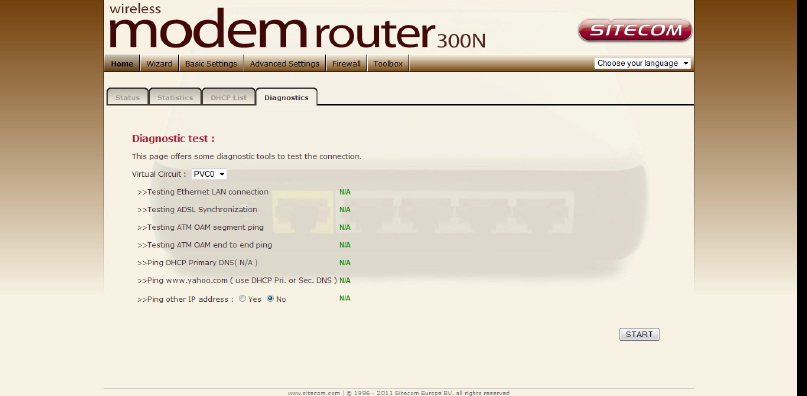
ATM VC
• Virtual Circuit: VPI (Virtual Path Identifier) and VCI (Virtual Channel
Identifier) define a virtual circuit.
• VPI: The valid range for the VPI is 0 to 255. Enter the VPI assigned to
you. This field may already be configured.
• VCI: The valid range for the VCI is 32 to 65535. Enter the VCI assigned to
you. This field may already be configured.
• ATM QoS: Select CBR to specify fixed (always-on) bandwidth for voice or
data traffic. Select UBR for applications that are non-time sensitive, such
as e-mail. Select VBR for burst traffic and bandwidth sharing with other
applications.
• PCR: Divide the DSL line rate (bps) by 424 (the size of an ATM cell) to
find the Peak Cell Rate (PCR). This is the maximum rate at which the
sender can send cells.
• SCR: The Sustain Cell Rate (SCR) sets the average cell rate (long-term)
that can be transmitted.
• MBS: Maximum Burst Size (MBS) refers to the maximum number of cells
that can be sent at the peak rate. Type the MBS, which is less than 65535
Encapsulation:
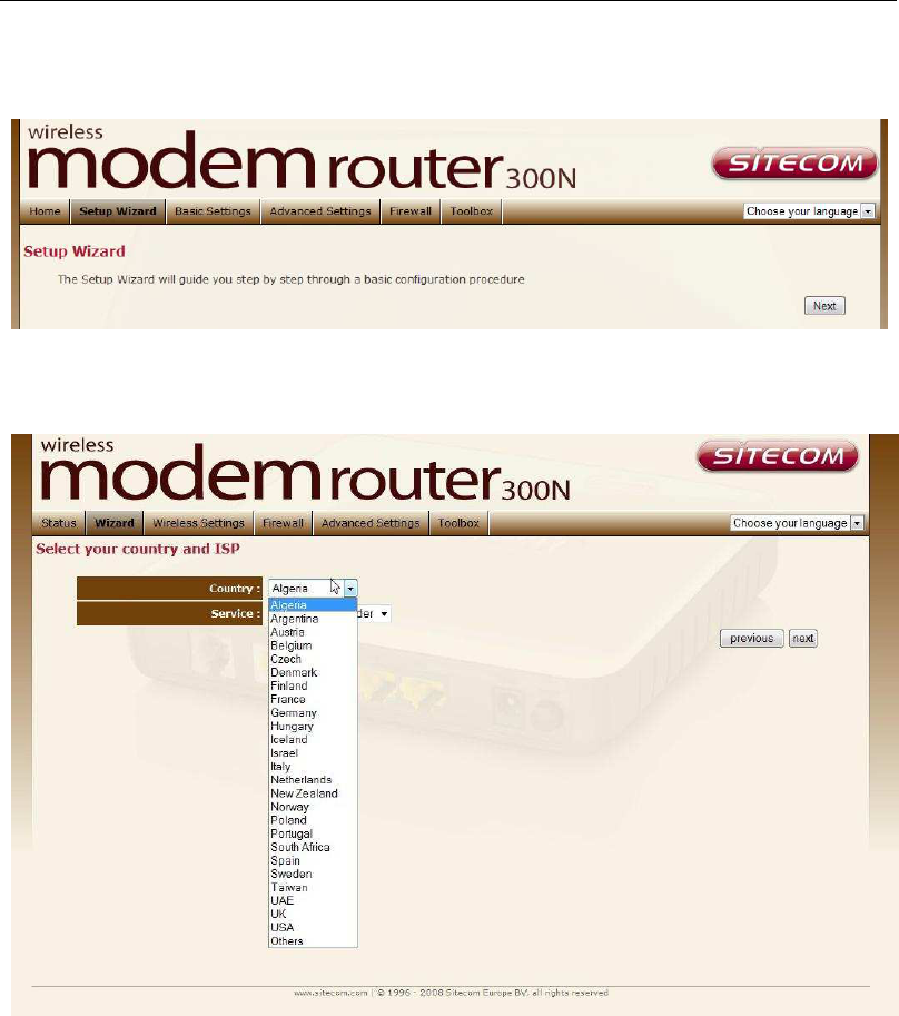
• ISP: Select the encapsulation type your ISP uses from the Encapsulation
list.
Choices vary depending on what you select in the Mode field.
If you select Bridge in the Mode field, select 1483 Bridged IP.
If you select Routing in the Mode field, select PPPoA, 1483 Bridged IP, 1483
Router IP or PPPoE.
PPPoE/PPPoA
• User Name: Enter the user name exactly as your ISP assigned.
• Password: Enter the password associated with the user name above.
• Encapsulation: select Bridge in the Mode field, select either PPPoA or
RFC 1483.
• select Routing in the Mode field, select PPPoA, RFC 1483, ENET ENCAP or
PPPoE.
• Multiplex: Select the method of multiplexing used by your ISP. Choices are
VC or LLC.
• Connection: The schedule rule(s) have priority over your Connection
settings.
• Always on: Select Always on Connection when you want your connection
up all the time.
• Connect on Demand: Select Connect on Demand when you don't want
the connection up all the time and specify an idle time-out in the Max Idle
Timeout field
• Get IP Address: Choose Static or Dynamic
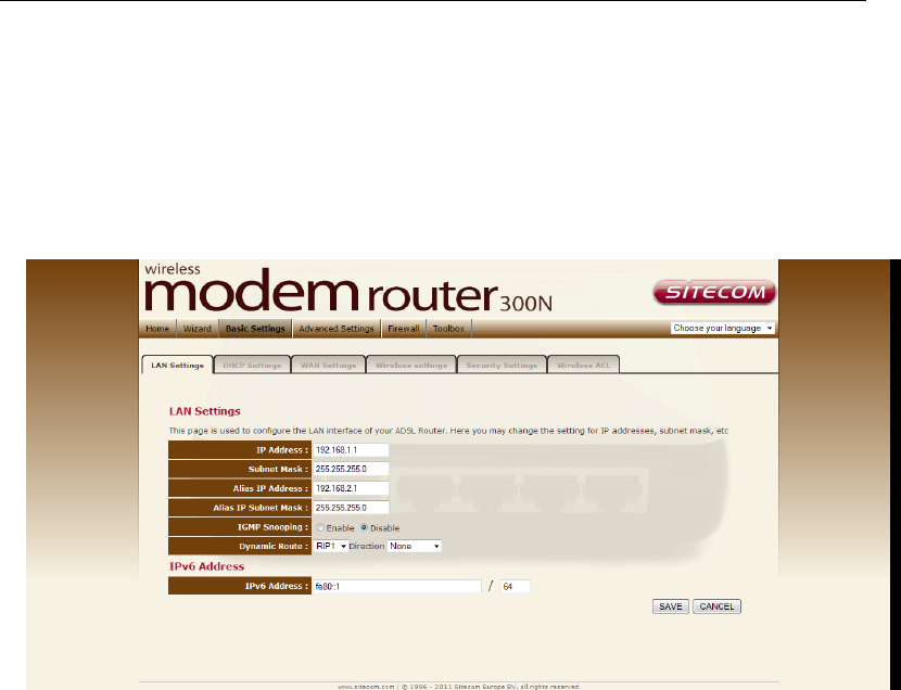
• Static IP Address: Enter the IP address of ADSL Router in dotted
decimal notation, for example, 192.168.1.254 (factory default).
• IP Subnet Mask: The default is 255.0.0.0. User can change it to other
such as 255.255.255.0.Type the subnet mask assigned to you by your ISP
(if given).
• Gateway: You must specify a gateway IP address (supplied by your ISP)
when you use 1483 Bridged IP in the Encapsulation field in the
previous screen.