527724
2
Zoom out
Zoom in
Previous page
1/43
Next page
Broadband Router
DC-207
Full Manual
Copyright
The contents of this publication may not be reproduced in any part or as
a whole, stored, transcribed in an information retrieval system, trans-
lated into any language, or transmitted in any form or by any means,
mechanical, magnetic, electronic, optical, photocopying, manual, or
otherwise, without the prior written permission.
Trademarks
All product, company, brand names are trademarks or registered trade-
marks of their respective companies. They are used for identification
purpose only. Specifications are subject to be changed without prior
notice.
FCC Interference Statement
This equipment has been tested and found to comply with the limits for
a Class B digital device pursuant to Part 15 of the FCC Rules. These
limits are designed to provide reasonable protection against radio inter-
ference in a commercial environment. This equipment can generate, use
and radiate radio frequency energy and, if not installed and used in
accordance with the instructions in this manual, may cause harmful
interference to radio communications. Operation of this equipment in a
residential area is likely to cause interference, in which case the user, at
his own expense, will be required to take whatever measures are neces-
sary to correct the interference.
CE Declaration of Conformity
This equipment complies with the requirements relating to electromag-
netic compatibility, EN 55022/A1 Class B
1. Introduction
Congratulations on your purchase of this outstanding broadband router.
This product is specifically designed for Small Office and Home Office
needs. It provides a complete SOHO solution for Internet surfing, and is
easy to configure and operate even for non-technical users. Instructions
for installing and configuring this product can be found in this manual.
Before you install and use this product, please read this manual carefully
for fully exploiting the functions of this product.
1.1 Functions and Features
Router Basic functions
Broadband modem and NAT Router
Connects multiple computers to a broadband (cable or DSL) modem or
an Ethernet router to surf the Internet.
Auto-sensing Ethernet Switch
Equipped with a 4-port auto-sensing Ethernet switch.
Printer sharing
Embedded a print server to allow all of the networked computers to
share one printer.
Built-in USB(parallel) host to connect to USB (parallel)printer for printer
sharing
WAN type supported
The router supports some wan types, Static ,Dynamic, PPPOE ,PPTP ,
Dynamic IP with Road Runner.
Firewall
All unwanted packets from outside intruders are blocked to protect your
Intranet.
DHCP server supported
All of the networked computers can retrieve TCP/IP settings automati-
cally from this product.
Web-based configuring
Configurable through any networked computer’s web browser using
Netscape or Internet Explorer.
Virtual Server supported
Enables you to expose WWW, FTP and other services on your LAN to be
accessible to Internet users.
User-Definable Application Sensing Tunnel
User can define the attributes to support the special applications requir-
ing multiple connections, like Internet gaming, video conferencing,
Internet telephony and so on, then this product can sense the applica-
tion type and open multi-port tunnel for it.
DMZ Host supported
Lets a networked computer be fully exposed to the Internet; this func-
tion is used when special application sensing tunnel feature is insuffi-
cient to allow an application to function correctly.
Statistics of WAN Supported
Enables you to monitor inbound and outbound packets
Security functions
Packet filter supported
Packet Filter allows you to control access to a network by analyzing the
incoming and outgoing packets and letting them pass or halting them
based on the IP address of the source and destination.
Domain Filter Supported
Let you prevent users under this device from accessing specific URLs.
URL Blocking Supported
URL Blocking can block hundreds of websites connection by simply a
keyword.
VPN Pass-through
The router also support vpn pass-through.
Advanced functions
System time Supported
Allow you to synchronize system time with network time server.
E-mail Alert Supported
The router can send its info by mail.
Dynamic dns Supported
At present,the router has 3 ddns.dyndns,TZO.com and dhs.org.
SNMP Supported
Because SNMP this function has many versions, anyway, the router
supports V1 and V2c.
Routing Table Supported
Now, the router supports static routing and two kinds of dynamic routing
RIP1 and RIP2.
Schedule Rule supported
Customers can control some functions, like virtual server and packet
filters when to
Access or when to block.
Other functions
UPNP (Universal Plug and Play)Supported
The router also supports this function. The applications: X-box, Msn
Messenger.
2. Hardware installation
2.1 Panel Layout
2.1.1 Front Panel
M1&M2 System status indicators, Green. M1 is flashed once per
second to indicate system is alive. When system is
busy, M2 is lighted.
WAN/Link Link status indicators, Green. The LED flickers when the
corresponding port is sending or receiving data
LAN/Speed
WAN/Speed
10/100 status indicators, Green. The LED flickers when
the corresponding port is transmitting or receiving data
in 10 or 100Mbps.
LAN/Link Link status indicators, Green. The LED flickers when the
corresponding port is sending or receiving data
RESET To reset system settings to factory defaults, please
follow the steps:
Power off the device,
Press the reset button and hold,
Power on the device,
Keep the button pressed about 5 seconds,
Release the button,
Watch the M1 and M2 LEDs, they will flash 8 times and
then M1 flash once per second.
2.1.2. Rear Panel
Port Description
5VDC Power inlet: DC 5V, 1.5A (minimum)
WAN the port where you will connect your cable (or DSL)
modem or Ethernet router.
Port 1-4 the ports where you will connect networked computers
and other devices.
PRINTER Printer Port
2.2 Procedure for Hardware Installation
1. Decide where to place your Broadband Router
You can place your Broadband Router on a desk or other flat surface, or
you can mount it on a wall. For optimal performance, place your Broad-
band Router in the center of your office (or your home) in a location that
is away from any potential source of interference, such as a metal wall
or microwave oven. This location must be close to power and network
connection.
2. Setup LAN connection
Wired LAN connection: connects an Ethernet cable from your computer’s
Ethernet port to one of the LAN ports of this product.
Figure 2-3 Setup of LAN and WAN connections for this product.
3. Setup WAN connection
Prepare an Ethernet cable for connecting this product to your cable/xDSL
modem or Ethernet backbone. Figure 2-3 illustrates the WAN connec-
tion.
4. Connecting this product with your printer (optional)
Use the printer cable to connect your printer to the printer port of this
product. (Optional)
5. Power on
Connecting the power cord to power inlet and turning the power switch
on, this product will automatically enter the self-test phase. When it is in
the self-test phase, the indicators M1 will be lighted ON for about 10
seconds, and then M1 will be flashed 3 times to indicate that the self-
test operation has finished. Finally, the M1 will be continuously flashed
once per second to indicate that this product is in normal operation.
3. Network settings and software instal-
lation
To use this product correctly, you have to properly configure the network
settings of your computers and install the attached setup program into
your MS Windows platform (Windows 95/98/NT/2000).
3.1 Make Correct Network Settings of Your
Computer
The default IP address of this product is 192.168.123.254, and the de-
fault subnet mask is 255.255.255.0. These addresses can be changed on
your need, but the default values are used in this manual. If the TCP/IP
environment of your computer has not yet been configured, you can
refer to Appendix A to configure it. For example,
configure IP as 192.168.123.1, subnet mask as 255.255.255.0 and
gateway as 192.168.123.254, or more easier,
configure your computers to load TCP/IP setting automatically, that is,
via DHCP server of this product.
After installing the TCP/IP communication protocol, you can use the
ping command to check if your computer has successfully connected to
this product. The following example shows the ping procedure for Win-
dows 95 platforms. First, execute the ping command
ping 192.168.123.254
If the following messages appear:
Pinging 192.168.123.254 with 32 bytes of data:
Reply from 192.168.123.254: bytes=32 time=2ms TTL=64
a communication link between your computer and this product has been
successfully established. Otherwise, if you get the following messages,
Pinging 192.168.123.254 with 32 bytes of data:
Request timed out.
There must be something wrong in your installation procedure. You have
to check the following items in sequence:
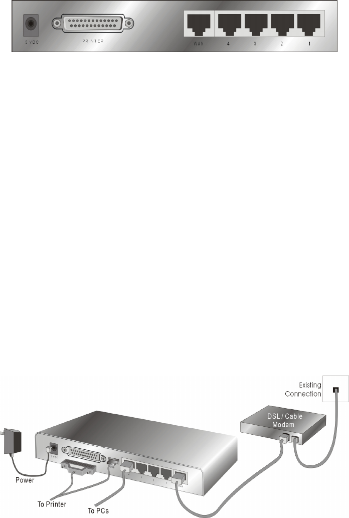
Is the Ethernet cable correctly connected between this product and your
computer?
Tip: The LAN LED of this product and the link LED of network card on
your computer must be lighted.
Is the TCP/IP environment of your computers properly configured?
Tip: If the IP address of this product is 192.168.123.254, the IP address
of your computer must be 192.168.123.X and default gateway must be
192.168.123.254.
3.2 Install the Software into Your Computers
Skip this section if you do not want to use the print server function of
this product.
Notice: If you are using Windows 2000/XP, please refer to Chap-
ter 5 Printer - 5.3 Configuring on Windows 2000 and XP
Platforms. It is not necessary to setup any program and
the print-server can work.
Insert the installation CD-ROM into the CD-ROM drive. The fol-
lowing window will be shown automatically. If it isn’t, please run
“install.exe” on the CD-ROM.
Click on the INSTALL button. Wait until the following Welcome
dialog to appear, and click on the Next button.
Select the destination folder and click on the Next button. Then,
the setup program will begin to install the programs into the des-
tination folder .Step 4: When the following window is displayed,
click on the Finish button.
Select the item to restart the computer and then click the OK
button to reboot your computer.
After rebooting your computer, the software installation proce-
dure is finished.
Now, you can configure the NAT Router (refer to Chapter 4) and
setup the Print Server (refer to Chapter 5).
4. Configuring the router
This product provides Web based configuration scheme, that is, config-
uring by your Web browser, such as Netscape Communicator or Internet
Explorer. This approach can be adopted in any MS Windows, Macintosh
or UNIX based platforms.
4.1 Start-up and login
Activate your browser, and disable the proxy or add the IP address
of this product into the exceptions. Then, type this product’s IP
address in the Location (for Netscape) or Address (for IE) field and press
ENTER. For example: http://192.168.123.254.
After the connection is established, you will see the web user interface of
this product. There are two appearances of web user interface: for gen-
eral users and for system administrator.
To log in as an administrator, enter the system password (the factory
setting is ”admin”) in the System Password field and click on the Log
in button. If the password is correct, the web appearance will be
changed into administrator configure mode. As listed in its main menu,
there are several options for system administration.
4.2 Status
This option provides the function for observing this product’s working
status:
WAN Port Status.
o If the WAN port is assigned a dynamic IP, there may ap-
pear a “Renew” or “Release” button on the Sidenote
column. You can click this button to renew or release IP
manually.
Statistics of WAN: enables you to monitor inbound and outbound
packets
4.3 Wizard
4.4 Basic settings
4.4.1 Primary setup
LAN IP Address: the local IP address of this device. The computers on
your network must use the LAN IP address of your product as their De-
fault Gateway. You can change it if necessary.
WAN Type: WAN connection type of your ISP. You can click Change
button to choose a correct one from the following four options:
Static IP Address: ISP assigns you a static IP address.
Dynamic IP Address: Obtain an IP address from ISP automati-
cally.
Dynamic IP Address with Road Runner Session Management.(e.g.
Telstra BigPond)
PPP over Ethernet: Some ISPs require the use of PPPoE to con-
nect to their services.
PPTP: Some ISPs require the use of PPTP to connect to their ser-
vices.
4.4.1.1 Static IP Address
WAN IP Address, Subnet Mask, Gateway, Primary and Secondary
DNS: enter the proper setting provided by your ISP.
4.4.1.2 Dynamic IP Address
Host Name: optional. Required by some ISPs, for example,
@Home.
Renew IP Forever: this feature enables this product to renew
your IP address automatically when the lease time is expiring--
even when the system is idle.
4.4.1.3 Dynamic IP Address with Road Runner Session Manage-
ment.(e.g. Telstra BigPond)
LAN IP Address is the IP address of this product. It must be the
default gateway of your computers.
WAN Type is Dynamic IP Address. If the WAN type is not correct,
change it!
Host Name: optional. Required by some ISPs, e.g. @Home.
Renew IP Forever: this feature enable this product renew IP ad-
dress automatically when the lease time is being expired even
the system is in idle state.
4.4.1.4 PPP over Ethernet
PPPoE Account and Password: the account and password your
ISP assigned to you. For security, this field appears blank. If you
don't want to change the password, leave it empty.
PPPoE Service Name: optional. Input the service name if your
ISP requires it. Otherwise, leave it blank.
Maximum Idle Time: the amount of time of inactivity before
disconnecting your PPPoE session. Set it to zero or enable Auto-
reconnect to disable this feature.
Maximum Transmission Unit (MTU): Most ISP offers MTU
value to users. The most common MTU value is 1492.
4.4.1.5 PPTP
My IP Address and My Subnet Mask: the private IP address
and subnet mask your ISP assigned to you.
Server IP Address: the IP address of the PPTP server.
PPTP Account and Password: the account and password your
ISP assigned to you. If you don't want to change the password,
keep it empty.
Connection ID: optional. Input the connection ID if your ISP re-
quires it.
Maximum Idle Time: the time of no activity to disconnect your
PPTP session. Set it to zero or enable Auto-reconnect to disable
this feature. If Auto-reconnect is enabled, this product will auto-
matically connect to ISP after system is restarted or connection is
dropped.
4.4.1.6 Virtual Computers
Virtual Computer enables you to use the original NAT feature, and allows
you to setup the one-to-one mapping of multiple global IP address and
local IP address.
Global IP: Enter the global IP address assigned by your ISP.
Local IP: Enter the local IP address of your LAN PC correspond-
ing to the global IP address.
Enable: Check this item to enable the Virtual Computer feature.
4.4.2 DHCP Server
Press “More>>
The settings of a TCP/IP environment include host IP, Subnet Mask,
Gateway, and DNS configurations. It is not easy to manually configure
all the computers and devices in your network. Fortunately, DHCP
Server provides a rather simple approach to handle all these settings.
This product supports the function of DHCP server. If you enable this
product’s DHCP server and configure your computers as “automatic IP
allocation” mode, then when your computer is powered on, it will auto-
matically load the proper TCP/IP settings from this product. The settings
of DHCP server include the following items:
DHCP Server: Choose “Disable” or “Enable.”
Lease Time: this feature allows you to configure IP’s lease time
(DHCP client).
IP pool starting Address/ IP pool starting Address: When-
ever there is a request, the DHCP server will automatically
allocate an unused IP address from the IP address pool to the re-
questing computer. You must specify the starting and ending
address of the IP address pool.
Domain Name: Optional, this information will be passed to the
client.
Primary DNS/Secondary DNS: This feature allows you to as-
sign DNS Servers
Primary WINS/Secondary WINS: This feature allows you to
assign WINS Servers
Gateway: The Gateway Address would be the IP address of an
alternate Gateway. This function enables you to assign another
gateway to your PC, when DHCP server offers an IP to your PC.
4.4.3 Change Password
You can change Password here. We strongly recommend you to change
the system password for security reasons.
4.5 Security settings
4.5.1 Domain filter
Domain Filter lets you prevent users under this device from accessing
specific URLs.
Domain Filter Enable: Check if you want to enable Domain Fil-
ter.
Log DNS Query: Check if you want to log the action when
someone accesses the specific URLs.
Privilege IP Addresses Range: Setting a group of hosts and
privilege these hosts to access network without restriction.
Domain Suffix: A suffix of URL to be restricted. For example,
".com", "xxx.com".
Action: When someone is accessing the URL met the domain-
suffix, what kind of action you want.
Check drop to block the access. Check log to log these access.
Enable: Check to enable each rule.
Example
In this example:
URL include “www.msn.com” will be blocked, and the action will
be record in log-file.
URL include “www.sina.com” will not be blocked, but the action
will be record in log-file.
URL include “www.google.com” will be blocked, but the action will
not be record in log-file.
IP address X.X.X.1~ X.X.X.20 can access network without restric-
tion.
4.5.2 Packet filter
Packet Filter enables you to control what packets are allowed to pass
the router. Outbound filter applies on all outbound packets. However,
Inbound filter applies on packets that destined to Virtual Servers or DMZ
host only. You can select one of the two filtering policies:
Allow all to pass except those match the specified rules
Deny all to pass except those match the specified rules
You can specify 8 rules for each direction: inbound or outbound. For
each rule, you can define the following:
Source IP address
Source port address
Destination IP address
Destination port address
Protocol: TCP or UDP or both.
Use Rule#
For source or destination IP address, you can define a single IP address
(4.3.2.1) or a range of IP addresses (4.3.2.1-4.3.2.254). An empty
implies all IP addresses.
For source or destination port, you can define a single port (80) or a
range of ports (1000-1999). Add prefix "T" or "U" to specify TCP or UDP
protocol. For example, T80, U53, U2000-2999. No prefix indicates both
TCP and UDP are defined. An empty implies all port addresses. Packet
Filter can work with Scheduling Rules, and give user more flexibility
on Access control. For Detail, please refer to Scheduling Rule.
Each rule can be enabled or disabled individually.
4.5.2.1 Inbound Filter:
To enable Inbound Packet Filter click the Inbound filter button and
check box next to Enable in the Inbound Packet Filter field.
Suppose you have SMTP Server (25), POP Server (110), Web Server
(80), FTP Server (21), and News Server (119) defined in Virtual Server
or DMZ Host.
Example 1
(1.2.3.100-1.2.3.149) They are allow to send mail (port 25), receive
mail (port 110), and browse the Internet (port 80)
(1.2.3.10-1.2.3.20) They can do everything (block nothing)
Others are all blocked.
Example 2
4.5.2.2 Outbound Filter:
To enable Outbound Packet Filter click the check box next to Enable in
the Outbound Packet Filter field.
Example 1
(192.168.123.100-192.168.123.149) They are allowed to send mail
(port 25), receive mail (port 110), and browse Internet (port 80); port
53 (DNS) is necessary to resolve the domain name.
(192.168.123.10-192.168.123.20) They can do everything (block noth-
ing)
Others are all blocked.
Example 2
(192.168.123.100-192.168.123.119) They can do everything except
read net news (port 119) and transfer files via FTP (port 21)
Others are allowed
After Outbound Packet Filter setting is configured, click the save
button.
4.5.3 MAC CTRL (MAC address access control)
MAC Address Control allows you to assign different access right for
different users and to assign a specific IP address to a certain MAC ad-
dress.
MAC Address Control: Check “Enable” to enable the “MAC Ad-
dress Control”. All of the settings in this page will take effect only
when “Enable” is checked.
Connection control: Check "Connection control" to enable the
controlling of which wired can connect to this device. If a client is
denied to connect to this device, it means the client can't access
to the Internet either. Choose "allow" or "deny" to allow or deny
the clients, whose MAC addresses are not in the "Control table"
(please see below), to connect to this device.
4.5.3.1 Controltable
"Control table" is the table at the bottom of the "MAC Address Control"
page. Each row of this table indicates the MAC address and the expected
IP address mapping of a client. There are four columns in this table:
MAC Address
MAC address indicates a specific client.
IP Address Expected IP address of the corresponding client. Keep it
empty if you don't care its IP address.
C When "Connection control" is checked, check "C" will
allow the corresponding client to connect to this device.
In this page, we provide the following Combobox and button to help you
to input the MAC address.
You can select a specific client in the “DHCP clients” Combobox, and
then click on the “Copy to” button to copy the MAC address of the client
you select to the ID selected in the “ID” Combobox.
Previous page and Next Page: To make this setup page simple and
clear, we have divided the “Control table” into several pages. You can
use these buttons to navigate to different pages.
4.5.4 Misc.
Remote Administrator Host/Port
In general, only Intranet user can browse the built-in web pages to
perform administration task. This feature enables you to perform ad-
ministration task from remote host. If this feature is enabled, only the
specified IP address can perform remote administration. If the specified
IP address is 0.0.0.0, any host can connect to this product to perform
administration task. You can use subnet mask bits "/nn" notation to
specified a group of trusted IP addresses. For example, "10.1.2.0/24".
NOTE: When Remote Administration is enabled, the web server port will
be shifted to 88. You can change web server port to other port, too.
Administrator Time-out
The time of no activity to logout automatically. Set it to zero to disable
this feature.
Discard PING from WAN side
When this feature is enabled, any host on the WAN cannot ping this
product.
VPN PPTP/IPSec Pass-Through
Please enable this feature, if you need to establish a PPTP or IPSEC
connection that will pass through this device.
4.6 Advanced settings
4.6.1 Virtual Servers
This product’s NAT firewall filters out unrecognized packets to protect
your Intranet, so all hosts behind this product are invisible to the outside
world. If you wish, you can make some of them accessible by enabling
the Virtual Server Mapping.
A virtual server is defined as a Service Port, and all requests to this
port will be redirected to the computer specified by the Server IP.
Virtual Server can work with Scheduling Rules, and give user more
flexibility on Access control. For Detail, please refer to Scheduling
Rule.
For example, if you have an FTP server (port 21) at 192.168.123.1, a
Web server (port 80) at 192.168.123.2, and a VPN server at
192.168.123.6, then you need to specify the following virtual server
mapping table:
Service Port Server IP Enable
21 192.168.123.1 V
80 192.168.123.2 V
1723 192.168.123.6 V
4.6.2 Special Applications
Some applications require multiple connections, like Internet games,
Video conferencing, Internet telephony, etc. Because of the firewall
function, these applications cannot work with a pure NAT router. The
Special Applications feature allows some of these applications to work
with this product. If the mechanism of Special Applications fails to make
an application work, try setting your computer as the DMZ host instead.
Trigger: the outbound port number issued by the application..
Incoming Ports: when the trigger packet is detected, the in-
bound packets sent to the specified port numbers are allowed to
pass through the firewall.
This product provides some predefined settings Select your application
and click Copy to to add the predefined setting to your list.
Note: At any given time, only one PC can use each Special Application
tunnel.
4.6.3 Misc
IP Address of DMZ Host
DMZ (DeMilitarized Zone) Host is a host without the protection of fire-
wall. It allows a computer to be exposed to unrestricted 2-way
communication for Internet games, Video conferencing, Internet teleph-
ony and other special applications.
NOTE: This feature should be used only when needed.
Non-standard FTP port
You have to configure this item if you want to access an FTP server
whose port number is not 21. This setting will be lost after rebooting.
4.6.4 Time
Get Date and Time by NTP Protocol
Selected if you want to Get Date and Time by NTP Protocol.
Time Server
Select a NTP time server to consult UTC time
Time Zone
Select a time zone where this device locates.
Set Date and Time manually
Selected if you want to Set Date and Time manually.
Function of Buttons
Sync Now: Synchronize system time with network time server
4.6.5 Logs
This page support two methods to export system logs to specific desti-
nation by means of syslog(UDP) and SMTP(TCP). The items you have to
setup including:
IP Address for Syslog
Host IP of destination where syslogs will be sent to.
Check Enable to enable this function.
IP addres of Outgoing mailserver
Input the SMTP server IP and port, which are concated with ':'. If you do
not specify port number, the default value is 25.
For example, "mail.your_url.com" or "192.168.1.100:26".
Log or Alart recipient
The recipients who will receive these logs. You can assign more than 1
recipient, using ';' or ',' to separate these email addresses.
4.6.6 DDNS (Dynamic DNS)
To host your server on a changing IP address, you have to use dynamic
domain name service (DDNS).
So that anyone wishing to reach your host only needs to know the name
of it. Dynamic DNS will map the name of your host to your current IP
address, which changes each time you connect your Internet service
provider.
Before you enable Dynamic DNS, you need to register an account on
one of these Dynamic DNS servers that we list in provider field.
To enable Dynamic DNS click the check box next to Enable in the
DDNS field.
Next you can enter the appropriate information about your Dynamic DNS
Server.
You have to define:
Provider
Host Name
Username/E-mail
Password/Key
You will get this information when you register an account on a Dynamic
DNS server.
4.6.7 SNMP
In brief, SNMP, the Simple Network Management Protocol, is a protocol
designed to give a user the capability to remotely manage a computer
network by polling and setting terminal values and monitoring network
events.
Enable SNMP
You must check either Local or Remote or both to enable SNMP function.
If Local is checked, this device will response request from LAN. If Re-
mote is checked, this device will response request from WAN.
Get Community
Setting the community of GetRequest your device will response.
Set Community
Setting the community of SetRequest your device will accept.
IP 1,IP 2,IP 3,IP 4
Input your SNMP Management PC’s IP here. User has to configure to
where this device should send SNMP Trap message.
SNMP Version
Please select proper SNMP Version that your SNMP Management soft-
ware supports.
4.7 Toolbox
4.7.1 Log
You can view the system log by clicking the Log button.
4.7.2 Firmware
You can upgrade firmware by clicking Upgrade button.
4.7.3 Back-up
You can backup your settings by clicking the Backup Setting button
and save it as a bin file. Once you want to restore these settings, please
click Firmware Upgrade button and use the bin file you saved.
4.7.4 Default
You can also reset this product to factory default by clicking the Reset
to default button.
4.7.5 Reboot
You can also reboot this product by clicking the Reboot button.
4.7.6 Misc
MAC Address for Wake-on-LAN
Wake-on-LAN is a technology that enables you to power up a networked
device remotely. In order to enjoy this feature, the target device must
be Wake-on-LAN enabled and you have to know the MAC address of this
device, say 00-11-22-33-44-55. Clicking "Wake up" button will make the
router to send the wake-up frame to the target device immediately.
5. Print server
This product provides the function of network print server for MS Win-
dows 95/98/NT/2000 and Unix based platforms.
5.1 Configuring on Windows 95/98
After you finished the software installation procedure described in Chap-
ter 3, your computer has possessed the network printing facility
provided by this product. For convenience, we call the printer connected
to the printer port of this product as server printer. On a Windows 95/98
platform, open the Printers window in the My Computer menu:
Now, yon can configure the print server of this product:
Find out the corresponding icon of your server printer, for exam-
ple, the HP LaserJet 6L. Click the mouse’s right button on that
icon, and then select the Properties item.
Click the Details item.
Choose the “PRTmate: (All-in-1)” from the list attached at the
Print To item. Be sure that the Printer Driver item is configured
to the correct driver of your server printer.
Click on the button of Port Settings.
Type in the IP address of this product and then click the OK but-
ton.
Make sure that all settings mentioned above are correct and then
click the OK button.
5.2 Configuring on Windows NT platforms
The configuration procedure for a Windows NT platform is similar to that
of Windows 95/98 except the screen of printer Properties.
Compared to the procedure in last section, the selection of Details is
equivalent to the selection of Ports, and Port Settings is equivalent to
Configure Port.
5.3 Configuring on Windows 2000/XP plat-
forms
Windows 2000 and XP have built-in LPR client, users could utilize this
feature to Print.
You have to install your Printer Driver on LPT1 or other ports
before you proceed with the following sequence.
Open Printers and Faxs
Select “Ports” page, Click “Add Port…”
Select “Standard TCP/IP Port”, and then click “New Port…”
Click Next and then provide the following information:
Type address of server providing LPD that is our NAT de-
vice:192.168.123.254
Select Custom, then click “Settings…”
Select “LPR”, type ” lp“ lowercase letter in “Queue Name:” And
enable “LPR Byte Counting Enabled”.
Apply your settings.
Appendix A – TCP/IP setup
Set up TCP/IP
If you are using a Fixed (specified) IP address, the following
changes are required:
The Gateway must be set to the IP address of the DC-202
The DNS should be set to the address provided by your ISP.
Using DHCP
To use DHCP, select the radio button Obtain an IP Address automati-
cally. This is the default Windows setting. Using this is recommended.
By default, the DC-202 will act as a DHCP Server.
Windows 98/ME
Right click the Network Neighbourhood icon on the desktop and click
Properties. The following window will be displayed:
Windows 2000/XP
Right click the My Network Places icon on the desktop and click Prop-
erties. The following window will be displayed:
Right click the Local Area Connection of the correct network card, and
then choose Properties.
If the list that appears on screen does not include a line, such as the one
that has been selected above ("TCP/IP -> network card"), then follow
the steps indicated below for adding this line:
Click on the button "Add"
Double-click on "Protocol"
Select "Microsoft" and thereafter "TCP/IP"
Click on "OK"
Wait a few seconds, so that TCP/IP can be added. Thereafter, click on
"OK" to leave the network properties screen. Restart your PC.
Select the line “TCP/IP -> Network card” as shown above. Click on the
button Properties to obtain a window similar to the following:
Check whether the setting "Obtain an IP address automatically" has
been selected, as is illustrated above. The DHCP server in the broadband
router will now assign an IP address to the PC.
Windows NT
Select Control Panel - Network, and, on the Protocols tab, select the
TCP/IP protocol, as shown below.
Click the Properties button to see a screen like the one below.
Select the network card for your LAN.
Select the appropriate radio button - Obtain an IP address from a DHCP
Server
Restart your PC, even if you have not made any changes.
Macintosh Clients
From your Macintosh, you can access the Internet via the DC-202. The
procedure is as follows.
1. Open the TCP/IP Control Panel.
2. Select Ethernet from the Connect via pop-up menu.
3. Select Using DHCP Server from the Configure pop-up menu. The
DHCP Client ID field can be left blank.
4. Close the TCP/IP panel, saving your settings.
Note:
If using manually assigned IP addresses instead of DHCP, the required
changes are:
Set the Router Address field to the DC-202's IP Address.
Ensure your DNS settings are correct.
Linux Clients
To access the Internet via the DC-202, it is only necessary to set the
DC-202 as the "Gateway".
Ensure you are logged in as "root" before attempting any
changes.
Fixed IP Address
By default, most Unix installations use a fixed IP Address. If you wish to
continue using a fixed IP Address, make the following changes to your
configuration.
Set your "Default Gateway" to the IP Address of the DC-202.
Ensure your DNS (Name server) settings are correct.
To act as a DHCP Client (recommended)
The procedure below may vary according to your version of Linux and X
-windows shell.
5. Start your X Windows client.
6. Select Control Panel - Network
7. Select the "Interface" entry for your Network card. Normally, this will
be called "eth0".
8. Click the Edit button, set the "protocol" to "DHCP", and save this
data.
9. To apply your changes
Use the "Deactivate" and "Activate" buttons, if available.
OR, restart your system.
Internet access
Windows 98/ME/2000
In the Taskbar, click on the Start button and select Settings - Con-
trol Panel - Internet options.
Select the tab page Connections and click on the button Settings.
Select "I want to configure my Internet connection manually" or "I
want to make a connection via a LAN network" and click on "Next
>".
Select "I want to connect via a LAN network" and click on "Next >".
Check carefully that all of the checkboxes in the screen Internet
configuration for a LAN have not been checked.
Continue with the steps in the wizard, until the task is completed.
The configuration is now completed.
Windows XP
In the Taskbar, click on the Start button and select - Settings –
Control Panel - Internet options.
Select the tab Connections and click the Setup button.
When the New Connection Wizard starts, click on Next.
Select Connect to internet and click on Next.
Select Set up my connection manually and click on Next.
Select Connect using a broadband connection that is always on
and click on Next.
Click on Finish to close the Wizard.
In the Taskbar, click on the Start button and select - Settings –
Control Panel - Internet options.
Select the Connections tab and click on the LAN Settings button.
Check carefully that none of the boxes in the Local Area Network
(LAN) Settings window are checked.
The configuration is now completed.
Appendix B – Troubleshooting
Reset to factory Default
There are 2 methods to reset to default.
Restore with RESET button
First, turn off the router and press the RESET button in. And
then, power on the router and hold the RESET button down until
the M1 and or M2 LED (or Status LED) start flashing, then move
away the hand. If LED flashes about 8 times, the RESTORE proc-
ess is completed. However, if LED flashes 2 times, repeat.
Restore directly when the router power on
First, hold the RESET button about 5 seconds(M1 will start flash-
ing about 5 times),move away the hand. The RESTORE process
is completed.
2


Need help? Post your question in this forum.

Forumrules


Report abuse

Libble takes abuse of its services very seriously. We're committed to dealing with such abuse according to the laws in your country of residence. When you submit a report, we'll investigate it and take the appropriate action. We'll get back to you only if we require additional details or have more information to share.

Product:

For example, Anti-Semitic content, racist content, or material that could result in a violent physical act.

For example, a credit card number, a personal identification number, or an unlisted home address. Note that email addresses and full names are not considered private information.

Forumrules

To achieve meaningful questions, we apply the following rules:

Register

Register getting emails for Sitecom DC-207 at:


You will receive an email to register for one or both of the options.


Get your user manual by e-mail

Enter your email address to receive the manual of Sitecom DC-207 in the language / languages: English as an attachment in your email.

The manual is 4,54 mb in size.


You will receive the manual in your email within minutes. If you have not received an email, then probably have entered the wrong email address or your mailbox is too full. In addition, it may be that your ISP may have a maximum size for emails to receive.

Others manual(s) of Sitecom DC-207

Sitecom DC-207 Quick start guide - Dutch - 14 pages


The manual is sent by email. Check your email

If you have not received an email with the manual within fifteen minutes, it may be that you have a entered a wrong email address or that your ISP has set a maximum size to receive email that is smaller than the size of the manual.

The email address you have provided is not correct.

Please check the email address and correct it.

Your question is posted on this page

Would you like to receive an email when new answers and questions are posted? Please enter your email address.


Info