108592
11
Zoom out
Zoom in
Previous page
1/100
Next page
LI 44630
LI 46630
de
en
fr
nl
it
es
pt
Gebrauchs- und
Montageanleitung
Operating and
installation instructions
Mode d’emploi et
notice de montage
Gebruiksaanwijzing en
montagevoorschrift
Istruzioni d’uso
e per il montaggio
Instrucciones de uso
y de montaje
Instruções de serviçio
e de montagem
2
Abb. 1
GAS ELEKTRO
GAZ ELECTR.
KAASU ELETT.
GASS EL.
de
Seite 03–15
en
page 16 28
fr
page 29 41
nl
pagina 42 54
it
pagina 55 67
es
página 68 80
pt
página 81 93
3
Gerätebeschreibung Betriebsarten
Betriebsarten
Abluftbetrieb:
Der Lüfter der Dunstabzugshaube saugt
den Küchendunst an und
leitet ihn durch den Fettfilter ins Freie.
Der Fettfilter nimmt die fettigen
Bestandteile des Küchendunstes auf.
Die Küche bleibt weitgehend frei von
Fett und Geruch.
D
Bei Abluftbetrieb der Dunstabzugs-
haube und gleichzeitigem Betrieb
schornsteinabhängiger Feuerungen
(wie z. B. Gas-, Öl- oder Kohleheizgeräte,
Durchlauferhitzer, Warmwasserbereiter)
muss für ausreichend Zuluft gesorgt
werden, die von der Feuerstätte zur Ver-
brennung benötigt wird.
Ein gefahrloser Betrieb ist möglich, wenn
der Unterdruck im Aufstellraum der
Feuerstätte von 4 Pa (0,04 mbar) nicht
überschritten wird.
Dies kann erreicht werden, wenn durch
nicht verschließbare Öffnungen, z. B. in
Türen, Fenstern und in Verbindung mit
Zuluft-/Abluftmauerkasten oder durch
andere techn. Maßnahmen, wie
gegenseitige Verriegelung o. ä., die
Verbrennungsluft nachströmen kann.
Bei nicht ausreichender Zuluft besteht
Vergiftungsgefahr durch zurückgesaugte
Verbrennungsgase.
Ein Zuluft-/Abluftmauerkasten allein stellt
die Einhaltung des Grenzwertes nicht
sicher.
Anmerkung: Bei der Beurteilung muss
immer der gesamte Lüftungsverbund der
Wohnung beachtet werden. Bei Betrieb von
Kochgeräten, z. B. Kochmulde und Gas-
herd wird diese Regel nicht angewendet.
Wenn die Dunstabzugshaube im Umluftbe-
trieb – mit Aktivkohlefilter – verwendet wird,
ist der Betrieb ohne Einschränkung
möglich.
Umluftbetrieb:
Hierzu muss ein Aktivkohlefilter
eingebaut werden (siehe Filter und
Wartung).
Das komplette Montage-Set sowie
die Ersatzfilter können Sie beim
Fachhandel erwerben.
Die entsprechenden Zubehör-Nummern
finden Sie am Ende dieser Gebrauchs-
anweisung.
Der Lüfter der Dunstabzugshaube saugt
den Küchendunst an und leitet ihn durch
den Fett- und Aktivkohlefilter gereinigt in
die Küche zurück.
Der Fettfilter nimmt die fettigen
Bestandteile des Küchendunstes auf.
Der Aktivkohlefilter bindet die
Geruchsstoffe.
Wird kein Aktivkohlefilter eingebaut,
können keine Geruchsstoffe des
Küchendunstes gebunden werden.
Schalter Licht/Lüfter Filterauszug
Gebrauchsanweisung
4
Vor dem ersten Benutzen
Wichtige Hinweise:
Diese Gebrauchsanweisung gilt für
mehrere Geräte-Ausführungen.
Es ist möglich, dass einzelne
Ausstattungsmerkmale beschrieben
sind, die nicht auf Ihr Gerät zutreffen.
Diese Dunstabzugshaube entspricht den
einschlägigen Sicherheitsbestimmungen.
Reparaturen dürfen nur von Fachkräften
durchgeführt werden.
Durch unsachgemäße Reparaturen
können erhebliche Gefahren für den
Benutzer entstehen.
Unter der Dunstabzugshaube nicht
flambieren.
Brandgefahr am Fettfilter durch
! aufsteigende Flammen.
Über einer Feuerstätte für feste
Brennstoffe (Kohle, Holz und dgl.) ist der
Betrieb der Dunstabzugshaube nur bedingt
gestattet (siehe Montageanweisung).
Gas-Kochmulden / Gas-Herde
Gas-Kochstellen immer sachgemäß
benutzen.
Wichtig:
Die Flammen der Gas-Kochstellen müssen
immer mit Kochgeschirr abgedeckt sein.
Durch die starke Hitzeentwicklung
der offenen Gasflammen könnte die
! Dunstabzugshaube beschädigt werden.
Bevor Sie das neue Gerät benutzen,
lesen Sie bitte sorgfältig die
Gebrauchsanweisung.
Sie enthält wichtige Informationen für Ihre
Sicherheit sowie zum Gebrauch und zur
Pflege des Gerätes.
Bewahren Sie die Gebrauchs- und
Montageanweisung ggf. für einen
Nachbesitzer gut auf.
Ist das Gerät beschädigt, dürfen Sie es
nicht in Betrieb nehmen.
Anschluss und Inbetriebnahme dürfen
nur von einem Fachmann durchgeführt
werden.
Wenn die Anschlussleitung dieses
Gerätes beschädigt wird, muss sie durch
den Hersteller oder seinen Kundendienst
oder eine ähnlich qualifizierte Person ersetzt
werden, um Gefährdung zu
vermeiden.
Verpackungsmaterial ordnungsgemäß
entsorgen (siehe Montageanweisung).
Dunstabzugshaube nur mit
eingesetzten Lampen betreiben.
Defekte Lampen sollten sofort ersetzt
werden, um Überlastung der restlichen
Lampen zu vermeiden.
Dunstabzugshaube nie ohne Fettfilter
betreiben.
Überhitzte Fette oder Öle können sich
leicht entzünden.
Darum Speisen mit Fetten oder Ölen,
z. B. Pommes frites, nur unter Aufsicht
zubereiten.
5
Bedienen der Dunstabzugshaube
Der Küchendunst wird am wirkungs-
vollsten beseitigt durch:
Einschalten der Dunstabzugshaube
bei Kochbeginn.
Ausschalten der Dunstabzugshaube
erst einige Minuten nach Kochende.
Lüfter – Aus –
Beleuchtung
Aus / Ein
Intensivstufe
Lüfterstufen
Lüfter – Aus –
Intensivstufe Reset-Taste mit
Sättigungsanzeige
für Fettfilter
Lüfterstufen
Beleuchtung
Aus / Ein
Ausschalten:
Die Dunstabzugshaube lässt sich auf
verschiedene Arten ausschalten.
Ausschalten 1:
Schiebeschalter auf 0 – Lüfter ausstellen.
Ausschalten 2:
Filterauszug bis Anschlag ein-
schieben. (Schiebeschalter bleibt wie
gewählt).
Zum erneuten Einschalten nur Filter-
auszug ausziehen.
Die Dunstabzugshaube startet mit der
zuletzt gewählten Lüftereinstellung.
Beleuchtung:
Die Beleuchtung kann zu jeder Zeit verwen-
det werden, auch wenn das Gerät ausge-
schaltet oder der Filterauszug eingescho-
ben wird.
Einschalten:
Filterauszug an der Griffleiste
ausziehen.
Gewünschte Lüftereinstellung wählen.
Störungen
Bei eventuellen Rückfragen oder
Störungen, Kundendienst anrufen.
(Siehe Kundendienststellenverzeichnis).
Bei Anruf bitte angeben:
E-Nr. FD
Tragen Sie die Nummern in obige Felder ein.
Die Nummern sind auf dem Typenschild,
nach Abnahme der Fettfilter, im Innenraum
der Dunstabzugshaube zu finden.
6
Filter und Wartung
Fettfilter:
Zur Aufnahme der fettigen Bestandteile
des Küchendunstes sind Metall-
Fettfilter eingesetzt.
Die Filtermatten bestehen aus unbrenn-
barem Metall.
Achtung:
Bei zunehmender Sättigung mit fetthaltigen
Rückständen erhöht sich die
Entflammbarkeit und die Funktion der
Dunstabzugshaube kann beeinträchtigt
werden.
Wichtig:
Durch rechtzeitiges Reinigen der
Metall-Fettfilter wird der Brandgefahr
vorgebeugt, die durch Hitzestau beim
Frittieren oder Braten entstehen kann.
Bei normalem Betrieb (täglich 1 bis 2
Stunden) müssen die Metall-Fettfilter
1 x im Monat gereinigt werden.
Sättigungsanzeige:
Bei Sättigung der Fettfilter blinkt die
Leuchtanzeige.
Spätestens dann Fettfilter reinigen.
Achten Sie darauf, dass dabei die
Fettfilter in regelmäßigem Abstand
(ca. 1 Monat) gereinigt werden.
Reinigen der Metall-Fettfilter:
Das Reinigen kann in der Geschirrspül-
maschine erfolgen. Dabei ist eine leichte
Verfärbung möglich.
Wichtig:
Stark gesättigte Metall-Fettfilter nicht
zusammen mit Geschirr reinigen.
Beim Reinigen von Hand, die Fettfilter in
heißer Spüllauge einweichen.
Danach abbürsten, gut ausspülen und
abtropfen lassen.
Aus- und Einbauen der Metall-Fettfilter:
Achtung: Die Halogenlampen müssen
ausgeschaltet und abgekühlt sein.
1. Ziehen Sie den Filterauszug bis zum
Anschlag aus.
2. Drücken Sie die Rasten am vorderen
Fettfilter ein und nehmen Sie den
Fettfilter ab.
4. Reinigen Sie die Fettfilter.
5. Setzen Sie die gereinigten Fettfilter
wieder ein.
6. Löschen Sie die Anzeige .
Drücken Sie die Taste .
3. Drücken Sie die Rasten am hinteren
Fettfilter ein und nehmen Sie den
Fettfilter ab.
7
Filter und Wartung
Aktivkohlefilter:
Zum Binden der Geruchsstoffe beim
Umluftbetrieb.
Achtung:
Bei zunehmender Sättigung mit fetthaltigen
Rückständen erhöht sich die
Entflammbarkeit und die Funktion der
Dunstabzugshaube kann beeinträchtigt
werden.
Wichtig:
Durch rechtzeitigen Wechsel des
Aktivekohlefilters wird der Brandgefahr
vorgebeugt, die durch Hitzestau beim
Frittieren oder Braten entstehen kann.
Einbauen:
Achtung: Die Halogenlampen müssen
ausgeschaltet und abgekühlt sein.
1. Bauen Sie die Fettfilter aus (siehe Aus-
und Einbauen der Metall-Fettfilter).
2. Setzen Sie den Aktivkohlefilter ein.
3. Rasten Sie die Lasche auf beiden Seiten
ein.
4. Bauen Sie die Fettfilter ein
(siehe Aus- und Einbauen der Metall-
Fettfilter).
Ausbauen:
Achtung: Die Halogenlampen müssen
ausgeschaltet und abgekühlt sein.
1. Bauen Sie die Fettfilter aus.
2. Drücken Sie die Lasche auf beiden
Seiten ein und nehmen Sie den
Aktivkohlefilter nach unten ab.
3. Wechsel des Aktivkohlefilters:
Bei normalem Betrieb (täglich 1 bis 2
Stunden) muss der Aktivkohlefilter
ungefähr 1 x im Jahr ausgetauscht
werden.
Der Aktivkohlefilter ist im Fachhandel
erhältlich (siehe Sonderzubehör auf
der letzten Seite).
Nur Originalfilter verwenden.
Dadurch wird die optimale Funktion
gewährleistet.
4. Bauen Sie die Fettfilter ein.
Entsorgung des alten Aktivkohlefilters:
Aktivkohlefilter enthalten keine
Schadstoffe. Sie können z. B. als
Restmüll entsorgt werden.
8
Reinigen und Pflegen
Dunstabzugshaube durch Ziehen des
Netzsteckers bzw. Ausschalten der
Sicherung stromlos machen.
Beim Reinigen der Fettfilter die
zugänglichen Gehäuseteile von
abgelagertem Fett reinigen.
Dadurch wird der Brandgefahr
vorgebeugt und die optimale Funktion
bleibt erhalten.
Zum Reinigen der Dunstabzugshaube
heiße Spüllauge oder mildes Fenster-
putzmittel verwenden.
Kratzen Sie angetrocknete Ver-
schmutzung nicht ab, sondern weichen
Sie diese mit einem feuchten Tuch auf.
Keine scheuernden Mittel oder
kratzende Schwämme verwenden.
Hinweis: Alkohol (Spiritus) nicht auf
Kunststoffflächen anwenden, es
könnten matte Stellen entstehen.
Vorsicht! Küche ausreichend
belüften, keine offene Flamme.
Die Bedientasten nur mit milder
Spüllauge und einem weichen, feuchten
Tuch reinigen.
Keinen Edelstahlreiniger für die
Bedientasten verwenden.
Edelstahloberflächen:
Verwenden Sie einen milden nicht
scheuernden Edelstahlreiniger.
Reinigen Sie nur in Schliffrichtung.
Edelstahloberflächen nicht mit
kratzenden Schwämmen und nicht mit
sand-, soda-, säure- oder chloridhaltigen
Putzmitteln reinigen!
Aluminium-, Lack- und Kunststoff-
oberflächen:
Verwenden Sie ein weiches, fusselfreies
Fenster- oder Microfasertuch.
Keine trockenen Tücher verwenden.
Verwenden Sie ein mildes Fenster-
reinigungsmittel.
Keine aggressiven, säure- oder laugen-
haltigen Reiniger verwenden.
Keine Scheuermittel verwenden.
Auswechseln der Lampen
1. Schalten Sie die Dunstabzugshaube aus
und machen Sie durch Ziehen des Netz-
steckers oder Ausschalten der Sicherung
die Dunstabzugshaube stromlos.
Die Halogenbirnen werden bei Betrieb
sehr heiß. Auch einige Zeit nach dem Aus-
schalten besteht noch Verbrennungs-
gefahr.
2. Nehmen Sie den Lampenring mit einem
Schraubenzieher oder ähnlichem ab.
3. Tauschen Sie die Halogenbirne aus
(handelsübliche Halogenbirne, 12 Volt,
max. 20 Watt, Sockel G4).
Achtung: Steckfassung.
Zum Anfassen der Birne ein sauberes
Tuch verwenden.
4. Rasten Sie den Lampenring wieder ein.
5. Stellen Sie durch Einstecken des
Netzsteckers oder durch Einschalten der
Sicherung die Stromversorgung wieder
her.
Hinweis: Sollte die Beleuchtung nicht
funktionieren, kontrollieren Sie, ob die
Lampen richtig eingesteckt sind.
9
Montageanweisung:
Wichtige Hinweise
Über Gas-Kochstellen ist die Montage
der Dunstabzugshaube bei einem
Mindestabstand von 650 mm – Abb. 1 –
nur zulässig, wenn folgende Nennwärme-
belastungen (Hs) nicht überschritten
werden:
Gas-Herde
Belastung einer Kochstelle max. 03,0 kW
Belastung aller Kochstellen max. 08,3 kW
Belastung des Backofens max. 03,9 kW
Gas-Kochmulden
Belastung einer Kochstelle max. 03,9 kW
Belastung aller Kochstellen max. 11,3 kW
Gas-Glaskeramikkochfeld
Die Angaben über Nennwärme-
belastung gelten nicht für geschlossene
Gas-Glaskeramikkochfelder.
Unbedingt die Angaben des Kochfeld-
Herstellers beachten.
Herde für feste Brennstoffe
Es gelten sinngemäß die maximalen
Nennwärmebelastungen und der
Mindestabstand wie bei Gas-Herden.
Über einer Feuerstätte für feste
Brennstoffe, von der eine Brandgefahr
(z. B. Funkenflug) ausgehen kann, ist die
Montage der Dunstabzugshaube nur dann
zulässig, wenn die Feuerstätte eine
geschlossene nicht abnehmbare
Abdeckung hat und die länderspezifischen
Vorschriften eingehalten werden.
Diese Einschränkung gilt nicht für Gas-
Herde und Gas-Mulden.
Je kleiner der Abstand zwischen
Dunstabzugshaube und Kochstellen desto
größer ist die Möglichkeit, dass sich durch
aufsteigenden Wasserdampf unten an der
Dunstabzugshaube Tropfen bilden können.
Altgeräte sind kein wertloser Abfall.
Durch umweltgerechte Entsorgung können
wertvolle Rohstoffe wiedergewonnen
werden.
Bevor Sie das Altgerät entsorgen, machen
Sie es unbrauchbar.
Ihr neues Gerät wurde auf dem Weg zu
Ihnen durch die Verpackung geschützt. Alle
eingesetzten Materialien sind umweltver-
träglich und wieder verwertbar. Bitte helfen
Sie mit und entsorgen Sie die Verpackung
umweltgerecht.
Über aktuelle Entsorgungswege informieren
Sie sich bitte bei Ihrem Fachhändler oder
bei Ihrer Gemeindeverwaltung.
Die Dunstabzugshaube ist für Abluft-
und Umluftbetrieb verwendbar.
Die Dunstabzugshaube immer über der
Mitte der Kochstellen anbringen.
Mindestabstand zwischen Elektro-
kochstellen und Unterkante der Dunstab-
zugshaube: 430 mm, Abb. 1.
Zusätzliche Hinweise bei Gas-Koch-
geräten:
Bei der Montage von Gaskochstellen
sind die national einschlägigen gesetzlichen
Bestimmungen (z. B. in Deutschland:
Technische Regeln Gasinstallation TRGI) zu
beachten.
Es müssen die jeweils gültigen Einbau-
vorschriften und die Einbauhinweise der
Gas-Gerätehersteller beachtet werden.
Die Dunstabzugshaube darf nur an
einer Seite neben einem Hochschrank oder
einer hohen Wand eingebaut werden.
Abstand mind. 300 mm.
10
Vor der Montage
Abluftbetrieb
Die Abluft wird über einen Lüftungsschacht
nach oben, oder direkt durch die Außen-
wand ins Freie geleitet.
D
Die Abluft darf weder in einen in Betrieb
befindlichen Rauch- oder Abgaskamin noch
in einen Schacht, welcher der Entlüftung
von Aufstellungsräumen von Feuerstätten
dient, abgegeben werden.
Bei der Ableitung von Abluft sind die
behördlichen und gesetzlichen
Vorschriften (z. B. Landesbauordnungen)
zu beachten.
Bei Abführung der Luft in nicht in Betrieb
befindliche Rauch- oder Abgaskamine ist
die Zustimmung des zuständigen
Schornsteinfegermeisters einzuholen.
D
Bei Abluftbetrieb der Dunstabzugs-
haube und gleichzeitigem Betrieb
schornsteinabhängiger Feuerungen (wie
z. B. Gas-, Öl- oder Kohleheizgeräte,
Durchlauferhitzer, Warmwasserbereiter)
muss für ausreichend Zuluft gesorgt
werden, die von der Feuerstätte zur
Verbrennung benötigt wird.
Ein gefahrloser Betrieb ist möglich, wenn
der Unterdruck im Aufstellraum der
Feuerstätte von 4 Pa (0,04 mbar) nicht
überschritten wird.
Dies kann erreicht werden, wenn durch
nicht verschließbare Öffnungen, z. B. in
Türen, Fenstern und in Verbindung mit
Zuluft-/Abluftmauerkasten oder durch
andere techn. Maßnahmen, wie
gegenseitige Verriegelung o. ä., die
Verbrennungsluft nachströmen kann.
Bei nicht ausreichender Zuluft besteht
Vergiftungsgefahr durch zurückgesaugte
Verbrennungsgase.
Ein Zuluft-/Abluftmauerkasten allein stellt
die Einhaltung des Grenzwertes nicht
sicher.
Anmerkung: Bei der Beurteilung muss
immer der gesamte Lüftungsverbund der
Wohnung beachtet werden. Bei Betrieb von
Kochgeräten, z. B. Kochmulde und Gas-
herd wird diese Regel nicht
angewendet.
Wenn die Dunstabzugshaube im Umluftbe-
trieb – mit Aktivkohlefilter – verwendet wird,
ist der Betrieb ohne Einschränkung
möglich.
Bei Abluftbetrieb sollte in der Dunstab-
zugshaube eine Rückstauklappe eingebaut
werden, wenn sie nicht im Abluftrohr oder
Mauerkasten vorhanden ist.
Ist der Dunstabzugshaube keine
Rückstauklappe beigelegt, kann sie über
den Fachhandel bezogen werden.
Wird die Abluft durch die Außenwand
geleitet, sollte ein Teleskop-Mauerkasten
verwendet werden.
Vor der Montage
Optimale Leistung der Dunstabzugs-
haube:
Kurzes, glattes Abluftrohr.
Möglichst wenig Rohrbögen.
Möglichst große Rohrdurchmesser (am
besten l 150 mm) und große Rohr-
bögen.
Der Einsatz von langen, rauhen
Abluftrohren, vielen Rohrbögen oder
kleineren Rohrdurchmessern führt zu
einer Abweichung von der optimalen
Luftleistung und gleichzeitig zu einer
Geräuscherhöhung.
Rundrohre
Kurzes Abluftrohr:
Innendurchmesser mind. 120 mm,
längeres Abluftrohr:
Innendurchmesser mind. 150 mm.
Flachkanäle müssen einen gleichwer-
tigen Innenquerschnitt wie Rundrohre
haben.
Sie sollten keine scharfen Umlenkun-
gen haben.
l 120 mm ca. 113 cm
2
l 150 mm ca. 177 cm
2
Bei abweichenden Rohrdurchmes-
sern: Dichtstreifen einsetzen.
Bei Abluftbetrieb für ausreichend Zuluft
sorgen.
Abluft direkt nach hinten:
Ist innerhalb des Oberschrankes nur bei
hohen Schränken, je nach Größe des
Abluftrohres möglich.
Dazu Öffnung in der Rückwand des
Oberschrankes, mit Auskerbung für
Elektro-Anschlusskabel herstellen.
11
600
m
in. 293
287
313
195
min.
435
Ø133/170
270
Abluft nach oben:
Das komplette
Montage-Set können
Sie beim Fachhan-
del erwerben.
Die entsprechenden
Zubehör-Nummern
finden Sie auf der
letzten Seite.
1. Dazu Öffnung in der Decke des Ober-
schrankes, mit Auskerbung für Elektro-
Anschlusskabel herstellen.
– Schablone
O
I liegt bei –.
2. Schrankboden – falls vorhanden – über
die gesamte Breite mind. 270 mm tief
ausschneiden.
Anschluss Abluftrohr l 150 mm:
Abluftrohr direkt am Abluftstutzen
befestigen.
Anschluss Abluftrohr l 120 mm:
Beiliegender Reduzierstutzen am
Luftaustritt befestigen.
Löcher am Luftaustritt müssen
abgedichtet sein.
Abluftrohr am Reduzierstutzen
befestigen.
Umluftbetrieb
Mit Aktivkohlefilter, wenn keine
Möglichkeit für Abluftbetrieb vorhanden
ist.
12
Vorbereiten Oberschrank
Diese Dunstabzugshaube ist zum Ein-
bauen in einen Oberschrank mit folgenden
Abmessungen vorgesehen:
Breite: 600 mm
Tiefe: 293 bis 350 mm
Höhe: mind. 435 mm.
Bei Schranktiefen von mehr als 293 mm
kann die Dunstabzugshaube nach hinten
versetzt werden, um z. B. ein Gewürzbord
vor der Dunstabzugshaube zu ermöglichen.
Dazu die Schablone
O
II entsprechend
weiter hinten anlegen.
Die Stabilität des Schrankes muss
während und nach der Montage
gewährleistet sein.
Auch beim Einbau am Ende der
Küchenzeile.
1. Je zwei Befestigungspunkte – rechts
und links – an den Schrankinnenseiten
anreißen und mit Stichel vorstechen.
Wenn gebohrt wird:
l 2 mm – max. 10 mm tief.
Zum Anreißen der Befestigungspunkte
beiliegende Schablone
O
II verwenden.
2. Beide Befestigungsplatten anschrauben.
3. Schrank mit Tür aufhängen und
ausrichten.
Auf Mindestabstand zwischen Koch-
stellen und Dunstabzugshaube achten!
Abb. 1.
13
3. Mit Schraubendreher (Akkuschrauber)
die beiden Befestigungsschrauben an-
drehen.
4. Wandabdeckung falls erforderlich auf
das benötigte Maß kürzen
(z. B. absägen).
Wandabdeckung mit den beiliegenden
Klipsen vormontieren.
Wandabdeckung am Oberschrank
festschrauben.
5. Netzanschlusskabel aus dem Schrank
herausführen.
6. Rohrverbindung im Oberschrank her-
stellen.
– Bei Bedarf Luftschlauch an der
Schrankdecke befestigen –.
7. Fettfilter wieder einsetzen
(siehe Gebrauchsanweisung).
Hinweis: Das Gehäuse der Dunstabzugs-
haube kann innerhalb des Oberschrankes
verkleidet werden (z. B. mit Spanplatten).
Dabei beachten:
Der Zwischenboden darf nicht auf das
Gehäuse der Dunstabzugshaube
aufgelegt werden.
Verkleidungen nicht am Gehäuse
befestigen.
Zugänglichkeit für Kundendienst
vorsehen.
Einbauen in den Oberschrank
Ausrichtung der Schranktüre
kontrollieren, bei Bedarf neu einstellen.
1. Fettfilter abnehmen
(siehe Gebrauchsanweisung).
2. Dunstabzugshaube von unten in den
Schrank heben, bis beide Befestigungs-
laschen sicher eingerastet sind.
Dunstabzugshaube im Schrank
ausrichten.
Beide Befestigungsschrauben vorsichtig
festziehen.
Kontrollieren, ob die Dunstabzugs-
haube fest im Schrank sitzt.
14
Einbauen in den Oberschrank
Sollte die Dunstabzugshaube im
Schrank nach hinten versetzt eingebaut
sein, können die Anschläge für den
Filterauszug nach vorne verschoben
werden.
Hierzu Schrauben lösen, Anschläge ver-
schieben und Schrauben wieder fest
anziehen.
Abluft Umluft
13,0 13,5
Konstruktionsänderungen im Rahmen der technischen
Entwicklung bleiben vorenthalten.
Gewicht in kg:
2. Griffleiste ausrichten und am Gerät
festschrauben.
Montage der Griffleiste:
An den Filterauszug muss eine
Griffleiste montiert werden.
Die Griffleiste kann eine zum Küchenmöbel
passende Holzleiste, oder eine im Sonder-
zubehör erhältliche Griffleiste sein (siehe
Sonderzubehör auf der letzten Seite).
1. Mit beiliegender Schablone
O
III die
Befestigungspunkte an Holzleiste
anreißen und mit Stichel vorstechen.
Wenn gebohrt wird:
l 2 mm – max. 10 mm tief.
15
Ausbauen aus dem Oberschrank
1. Elektrische Verbindung lösen.
2. Rohrverbindungen lösen.
3. Filter ausbauen.
4. Befestigungsschrauben links und rechts
lösen, bis sich die Dunstabzugshaube
nicht mehr weiter absenkt.
Dunstabzugshaube beim Lösen der
Befestigungsschrauben nicht anheben.
5. Dunstabzugshaube kurz anheben bis
die Befestigungslaschen ausrasten und
das Gerät nach unten absenken.
Befestigungsschrauben können
überstehen.
Beim Anheben der Dunstabzugshaube
den Filterauszug nicht mit Gewalt
einschieben.
6. Vorbereiten für erneuten Einbau:
Befestigungsschrauben links und rechts
eindrehen, bis die Laschen seitlich
ausgeschwenkt sind.
Elektrischer Anschluss
Die Dunstabzugshaube darf nur an eine
vorschriftsmäßig installierte Schutzkontakt-
steckdose angeschlossen werden. Die
Schutzkontaktsteckdose möglichst
zugänglich in der Nähe der Dunstabzugs-
haube anbringen.
Die Schutzkontaktsteckdose sollte über
einen eigenen Stromkreis angeschlos-
sen werden.
Elektrische Daten:
Sie sind auf dem Typenschild nach
Abnahme der Filterrahmen – im Innenraum
des Gerätes – zu finden.
Bei Reparaturen das Gerät generell
stromlos machen.
Länge der Anschlussleitung: 1,30 m.
Bei erforderlichem Festanschluss:
Die Dunstabzugshaube darf nur durch
einen beim zuständigen Elektrizitäts-
Versorgungsunternehmen eingetragenen
Elektro-Installateur angeschlossen werden.
Installationsseitig ist eine Trennvorrichtung
vorzusehen. Als Trennvorrichtung gelten
Schalter mit einer Kontaktöffnung von mehr
als 3 mm und allpoliger Abschaltung.
Dazu gehören LS-Schalter und Schütze.
Diese Dunstabzugshaube entspricht den
EG-Funkentstörbestimmungen.
16
Operating modes
This can be achieved if the combustion air
is able to flow through non-lockable
openings, e.g. in doors, windows and in
conjunction with an air supply/air-intake wall
box or by other technical procedures such
as reciprocal interlocking.
If the air intake is inadequate, there is a
risk of poisoning from combustion gases
which are drawn back into the room.
An air-intake/exhaust-air wall box by itself is
no guarantee that the limiting value will not
be exceeded.
Note: When assessing the overall
requirement, the combined ventilation
system for the entire household must be
taken into consideration. This rule does not
apply to the use of cooking appliances,
such as hobs and ovens.
Unrestricted operation is possible if the
extractor hood is used in recirculating mode
– with activated carbon filter.
Circulating-air mode:
An activated carbon filter must be fitted
for this operating mode (see Filters and
maintenance).
The complete installation set and
replacement filters can be obtained from
specialist outlets.
The corresponding accessory numbers
can be found at the end of these
operating instructions.
The extractor-hood fan extracts the
kitchen vapours which are purified in the
grease filter and activated carbon filter
and then conveyed back into the
kitchen.
The grease filter absorbs the grease
particles in the kitchen vapours.
The activated carbon filter binds the
odorous substances.
If no activated carbon filter is installed,
it is not possible to bind the odorous
substances in the cooking vapours.
Light / fan switches Filter drawer
Description of appliance
Operating instructions:
Operating modes
Exhaust-air mode:
The extractor-hood fan extracts the
kitchen vapours and conveys them
through the grease filter into the
atmosphere.
The grease filter absorbs the solid
particles in the kitchen vapours.
The kitchen is kept almost free of grease
and odours.
D
If the extractor hood is operated in
exhaust-air mode at the same time as a
flue-type heater (e.g. gas, oil or solid-fuel
heater, instantaneous water heater, boiler),
ensure that there is an adequate air
supply which the heater requires for
combustion.
Safe operation is possible provided that the
partial vacuum in the room in which the
heater is installed does not exceed 4 Pa
(0.04 mbar).
17
Before using for the first time
Important notes:
The Instructions for Use apply to several
versions of this appliance. Accordingly,
you may find descriptions of individual
features that do not apply to your
specific appliance.
This extractor hood complies with all
relevant safety regulations.
Repairs should be carried out by
qualified technicians only.
Improper repairs may put the user at
considerable risk.
Do not flambé food directly under the
extractor hood.
Risk of grease filter catching fire due
! to flames.
Restrictions apply to the use of the
extractor hood over a solid-fuel burner
(coal, wood, etc.). (See Installation
instructions).
Gas hobs / gas cookers
Always use gas hobs in a proper and
safe manner.
Important:
The flames from the gas hob must always
be covered by pots or pans.
The intense heat generated by the gas
flames could cause damage to the
! extractor hood.
Before using your appliance for the first
time, please read these Instructions for
Use carefully. They contain important
information concerning your personal
safety as well as on use and care of the
appliance.
Please retain the operating and
installation instructions for a subsequent
owner.
Do not use the appliance if damaged.
The appliance is not intended for use
by young children or infirmed persons
without supervision.
Young children should be supervised to
ensure they do not play with the appliance.
If the connecting cable for this
appliance is damaged, the cable must be
replaced by the manufacturer or his
customer service or a similarly qualified
person in order to prevent serious injury to
the user.
The appliance may be connected to
the mains by a qualified technician only.
Dispose of packaging materials
properly (see Installation instructions).
Light bulbs must always be fitted when
the extractor hood is in use.
Defective bulbs should be replaced
immediately to prevent the remaining bulbs
from overloading.
Never operate the extractor hood
without a grease filter.
Overheated fat or oil can easily catch
fire.
If you are cooking with fat or oil, e.g. chips,
etc., never leave the cooker unattended.
18
Operating the extractor hood
Cooking vapours are best eliminated
by:
Switching on the extractor hood when
you start cooking.
Only switching off the extractor hood
a few minutes after you have finished
cooking.
Fan on / off
Light
on / off
Intensive setting
Fan settings
Fan on / off
Intensive setting Reset button with
saturation display
for grease filter
Fan settings
Light
on / off
Switching off:
The extractor hood can be switched off in
various ways.
Switch-off 1:
Sliding switch to 0 – switch off fans.
Switch-off 2:
Push in filter drawer to stop. (Sliding
switch remains as selected).
To switch on the extractor again, just
pull out the filter unit.
The extractor hood will start at the most
recent fan setting.
Light:
The light can be switched on at any time
even when the appliance is off or the filter
drawer is inserted.
Switching on:
Take hold of filter drawer handle and pull
out the drawer.
Select the required fan setting.
Faults
If you have any queries or the appliance is
faulty, please call customer service
(see list of customer service units).
Please give the following details when you
call:
Product no. (E-Nr.) Serial no. (FD)
Enter the numbers in the above box. The
numbers can be found on the rating plate
inside the extractor hood following removal
of the filter screen.
19
4. Clean the filters.
5. Insert the clean filters back into the hood.
6. Cancel the in the display.
Press the button.
Grease filters:
Metal-mesh filters are used to trap the
grease particles in the cooking vapours.
The filter mats are made from non-
combustible metal.
Caution:
As the filter becomes more and more
saturated with grease, there is an increased
risk of fire and the function of the extractor
hood may be impaired.
Important:
Clean the metal-mesh grease filters at
regular intervals to prevent the risk of fire
from the accumulation of heat when
deep-fat frying or roasting.
If used in normal mode (daily 1 to 2
hours), the metal-mesh grease filter must
be cleaned 1x a month.
Saturation indicator:
When the grease filter is saturated, the
indicator starts flashing.
You should now change the grease filter if
you have not already done so.
Ensure that the grease filters are cleaned
at regular intervals (approx. 1 month).
Cleaning the metal-mesh grease filters:
The filters can be cleaned in a
dishwasher. However, they may become
slightly discoloured.
Important:
Do not wash highly saturated metal-
mesh grease filters with other utensils.
If cleaning the filters by hand, soak them in
a hot soap solution. Then brush the filters,
rinse thoroughly and leave to drain.
Filters and maintenance
Removing and inserting the metal-mesh
grease filters:
Warning: The halogen bulbs must be
switched off and cool.
1. Pull the filter drawer all the way out.
2. Depress both catches at the front of the
grease filter and remove the grease filter.
3. Depress the catches at the rear of the
grease filter and remove the grease filter.
20
3. Engage the catches at both sides.
4. Insert the metal-mesh grease filters (see
”Removing and inserting the metal-mesh
grease filters”).
Removing the filter:
Warning: The halogen bulbs must be
switched off and cool.
1. Remove the metal-mesh filters.
2. Depress the catches on both sides of
the filter and remove the activated
carbon filter.
3. Replacing the activated carbon filter:
A replacement filter can be obtained
from any authorized dealer
(see optional accessories).
Use original filters only.
This will ensure maximum
performance.
4. Insert the grease filters.
Disposing of the old activated carbon
filter:
Activated carbon filters do not contain
any pollutants and can be disposed of
with domestic refuse.
Filters and maintenance
Activated carbon filter:
For neutralizing odours in recirculating
mode.
Caution:
As the filter becomes more and more
saturated with grease, there is an increased
risk of fire and the function of the extractor
hood may be impaired.
Important:
Change the activated carbon filter promptly
to prevent the risk of fire from the
accumulation of heat when deep-fat frying
or roasting.
Inserting the filter:
Warning: The halogen bulbs must be
switched off and cool.
1. Remove the metal-mesh filters
(see "Removing and inserting the metal-
mesh grease filters").
2. Insert the activated carbon filter.
21
Cleaning and care
Isolate the extractor hood by pulling out
the mains plug or switching off the fuse.
When cleaning the grease filters, remove
grease deposits from accessible parts of
the housing. This prevents the risk of fire
and ensures that the extractor hood
continues operating at maximum
efficiency.
Clean the extractor hood with a hot soap
solution or a mild window cleaner.
Do not scrape off dried-on dirt but wipe
off with a damp cloth.
Do not use scouring agents or abrasive
sponges.
Note: Do not use alcohol (spirit) on
plastic surfaces, as dull marks may
appear.
Caution: Ensure that the kitchen is ade-
quately ventilated. Avoid naked flames!
Clean the operating buttons with a mild
soapy solution and a soft, damp cloth only.
Do not use stainless-steel cleaner to clean
the operating buttons.
Stainless steel surfaces:
Use a mild non-abrasive stainless steel
cleaner.
Clean the surface in the same direction
as it has been ground and polished.
Do not use any of the following to clean
stainless steel surfaces: abrasive sponges,
cleaning agents containing sand, soda, acid
or chloride!
Aluminium and plastic surfaces:
Use a soft, non-linting window cloth or
micro-fibre cloth.
Do not use dry cloths.
Use a mild window cleaning agent.
Do not use aggressive, acidic or caustic
cleaners.
Do not use abrasive agents.
4. Re-insert the bulb ring.
5. Restore the power by inserting the mains
plug or switching on the fuse.
Note: If the light does not function, check
that the bulbs have been inserted correctly.
Replacing the light bulbs
1. Switch off the extractor hood and pull
out the mains plug or switch off the
electricity supply at the fuse box.
When switched on, the halogen bulbs
become very hot. Even for some time after
the bulbs have been switched off there is
still a risk of burns.
2. Remove the bulb ring with a screwdriver
or similar tool.
3. Replace the halogen light bulb
(conventional halogen bulb, 12 Volt,
max. 20 Watt, G4 bulbholder).
Caution: Plug-in bulbholder.
Take hold of the bulb with a clean cloth.
22
Important information
Installation Instructions:
The installation of the extractor hood
above gas cooking devices, at a
minimum height of 650 mm – Fig. 1 – is
permitted provided that the following
nominal heat loads (Hs) are not exceeded:
Gas cookers
Load of one hotplate max. 03.0 kW
Load of all hotplates max. 08.3 kW
Load of the oven max. 03.9 kW
Gas hobs
Load of one hotplate max. 03.9 kW
Load of all hotplates max. 11.3 kW
Gas ceramic hotplate
The nominal heat load specifications do
not apply to closed gas ceramic hobs.
Always observe the specifications of the
hob manufacturer.
Solid-fuel cookers
The maximum nominal heat loads and
the minimum distance are the same as
for gas cookers.
The extractor hood must not be
installed over a solid fuel cooker – a
potential fire hazard (e.g. flying sparks) –
unless the cooker features a closed,
non-removable cover and all national
regulations are observed.
The smaller the gap between the
extractor hood and hotplates, the greater
the likelihood that droplets will form on the
underside of the extractor hood.
Old appliances are not worthless
rubbish. Valuable raw materials can be
reclaimed by recycling old appliances.
Before disposing of your old appliance,
render it unusable.
You received your new appliance in a
protective shipping carton. All packaging
materials are environmentally friendly and
recyclable. Please contribute to a better
environment by disposing of packaging
materials in an environmentally-friendly
manner.
Please ask your dealer or inquire at your
local authority about current means of
disposal.
The extractor hood can be used in
exhaust air or circulating air mode.
Always mount the extractor hood over
the centre of the hob.
Minimum distance between electric
hob and bottom edge of extractor hood:
430 mm, Fig. 1.
Additional information concerning gas
cookers:
When installing gas hotplates, comply
with the relevant national statutory
regulations (e.g. in Germany: Technische
Regeln Gasinstallation TRGI).
Always comply with the currently valid
regulations and installation instructions
supplied by the gas appliance
manufacturer.
Only one side of the extractor hood
may be installed next to a high-sided unit
or high wall. Gap at least 300 mm.
23
Prior to installation
Exhaust-air mode
The exhaust air is discharged upwards
through a ventilation shaft or directly
through the outside wall into the open.
D
Exhaust air must not be discharged via
a smoke or exhaust gas flue which is
already in use or via a shaft which is used
for ventilating rooms in which fireplaces are
located.
Discharge exhaust air in accordance
with official and statutory regulations
(e.g. national building regulations).
Discharge of air into smoke or exhaust air
flues which are not in use requires the
consent of a heating engineer.
D
If the extractor hood is operated in
exhaust-air mode at the same time as a
flue-type heater (e.g. gas, oil or solid-fuel
heater, instantaneous water heater, boiler),
ensure that there is an adequate air
supply which the heater requires for
combustion.
Safe operation is possible provided that the
partial vacuum in the room in which the
heater is installed does not exceed 4 Pa
(0.04 mbar).
This can be achieved if the combustion air
is able to flow through non-lockable
openings, e.g. in doors, windows and in
conjunction with an air supply/air-intake wall
box or by other technical procedures such
as reciprocal interlocking.
If the air intake is inadequate, there is a
risk of poisoning from combustion gases
which are drawn back into the room.
An air-intake/exhaust-air wall box by itself is
no guarantee that the limiting value will not
be exceeded.
Note: When assessing the overall
requirement, the combined ventilation
system for the entire household must be
taken into consideration. This rule does not
apply to the use of cooking appliances,
such as hobs and gas cookers.
The extractor hood can be used without
restriction in circulating air mode – with an
activated carbon filter.
For exhaust air mode a one-way flap
should be installed in the extractor hood
unless already installed in the exhaust air
pipe or wall box.
If a one-way flap is not enclosed with the
extractor hood, you purchase one from
your dealer.
If the exhaust air is conveyed through
the outside wall, a telescopic wall box
should be used.
24
Before installation
Optimum efficiency of the extractor
hood:
Short, smooth exhaust pipe.
As few bends as possible.
Pipe diameter as large as possible
(ideally 150 mm dia.) and wide pipe
bends.
If long, rough exhaust-air pipes,
many pipe bends or smaller pipe
diameters are used, the air extraction
rate will no longer be at an optimum
level and there will be an increase in
noise.
Round pipes
Short exhaust air pipe:
inside diameter min. 120 mm,
Longer exhaust air pipe:
inside diameter min. 150 mm.
Flat ducts must have an inside
cross-section equivalent to that of the
round pipes.
There should be no sharp bends.
l 120 mm dia. approx. 113 cm
2
l 150 mm dia. approx. 177 cm
2
If pipe diameters differ, insert sealing
strip.
Ensure that there is an adequate air
supply for exhaust air mode.
Exhaust air directed backwards:
Only possible inside tall wall cupboards
depending on the size of the exhaust air
pipe.
Make a hole in the rear panel of the wall
cupboard, cutting out a notch for the
power supply cable.
Exhaust air directed upwards:
The complete
installation set can
be obtained from
specialist outlets.
The corresponding
accessory numbers
can be found at the
end of these opera-
ting instructions.
1. Make a hole in the top of the wall cupbo-
ard, cutting out a notch for the power
supply cable.
– template
O
I enclosed –.
2. If fitted, cut out the cupboard base to a
min. depth of 270 mm over the entire
width.
Connecting a 150 mm exhaust pipe:
Attach the exhaust pipe directly to the air
connector.
Connection of 120 mm l exhaust air
pipe:
Attach enclosed reducing connector to
the air outlet.
Holes in the air outlet must be sealed.
Attach exhaust air pipe to the reducing
connector.
Circulating-air mode
With activated carbon filter if exhaust-air
mode is not possible.
600
m
in. 293
287
313
195
min.
435
Ø133/170
270
25
Preparing the wall cupboard
This extractor hood is designed to be
installed in a wall cupboard with the follo-
wing dimensions:
width: 600 mm
depth: 293 to 350 mm
height: min. 435 mm.
If the cupboard is deeper than 293 mm,
the extractor hood can be moved back,
e.g. to put a spice rack in front of the
extractor hood.
To do this, place the template
O
II further
back.
Ensure that the cupboard is stable both
during and after installation, even if fitted at
the end of a row of kitchen units.
1. Mark two attachment points on both the
right and left inside faces of the cup-
board and make holes with a bradawl.
When you drill:
2 mm diameter – max. 10 mm in depth.
Use the enclosed template
O
II to mark
the attachment points.
2. Screw on both attachment plates
3. Attach the door to the cupboard and
align.
Observe the minimum distance
between hotplates and extractor hood!
Fig. 1.
26
3. Tighten the two fixing screws with a
screwdriver (cordless).
4. If required, shorten the wall cover to the
required dimension (e.g. saw off).
Attach the wall cover with the enclosed
clips.
Screw the wall cover to the wall
cupboard.
5. Feed the mains connection cable out of
the cupboard.
6. Connect the pipes in the wall cupboard.
– If required, attach the air hose to the
cupboard ceiling –.
7. Re-insert grease filter
(see Operating instructions).
Note: The extractor hood housing can be
clad inside the wall cupboard (e.g. with
chipboard).
If so, observe the following:
The intermediate base must not be
placed on the extractor hood housing.
Never attach cladding to the housing.
Provide access for customer service.
Fitting into wall cupboard
Check door alignment and readjust if
necessary.
1. Remove grease filter
(see Operating instructions).
2. Lift the extractor hood into the cupboard
from below until both fixing lugs have
locked firmly into position.
Align the extractor hood in the
cupboard.
Carefully tighten both fastening screws.
Check that the extractor hood is
secure in the cupboard.
27
Fitting into wall cupboard
If the extractor hood is to be installed
further back in the cupboard, the stops
for the filter drawer can be moved
forwards.
To do this, undo the screws, move the
stops and retighten the screws.
2. Align handle moulding and screw to the
appliance.
Exhaust air Circulating air
13,0 13,5
We reserve the right to construction changes within the
context of technical development.
Weight in kg:
Attaching the handle moulding:
A handle moulding must be attached to
the filter drawer.
This handle moulding may be a wooden
strip which matches the kitchen units or a
handle moulding available as an optional
accessory (see optional accessories on the
back page).
1. Using the enclosed template
O
III , mark
the attachment points on the wooden
strip and make holes with a bradawl.
When you drill:
2 mm dia – max. 10 mm in depth.
28
Electrical connection
WARNING: THIS APPLIANCE MUST BE
EARTHED
IMPORTANT: Fitting a Different Plug:
The wires in the power cord are colour-
coded as follows:
Green and Yellow Earth
Blue Neutral
Brown Live
If you fit your own plug, the colours of
these wires may not correspond with the
identifying marks on the plug terminals.
Proceed as follows:
1. Connect the green and yellow (Earth)
wire to the terminal in the plug marked
‘E’ or with the symbol ( ), or
coloured green or green and yellow.
2. Connect the blue (Neutral) wire to the
terminal in the plug marked ‘N’ or
coloured black.
3. Connect the brown (Live) wire to the
terminal marked ‘L’, or coloured red.
The extractor hood may be connected to
a correctly installed earthed socket only.
Attach the earthed socket near the
extractor hood in an accessible position.
The earthed socket should be
connected via its own power circuit.
If appliances do not feature the OFF
delay function, the indicator may start flas-
hing when the extractor hood has been
switched off for several hours via a separa-
te switch, even though the grease filters are
not yet saturated.
(See instructions for use, section on filter
and maintenance).
Electrical specifications:
These can be found on the rating plate
inside the appliance following removal of
the filter frames.
Before carrying out repairs, always
isolate the appliance.
Length of the connection cable: 1.30 m.
If permanent connection is required:
The extractor hood may only be connected
by an electrician registered with the local
electricity board.
A disconnecting device must be provided
on the installation side. Switches with a
contact opening of more than 3 mm and
all-pole disconnection are regarded as
disconnecting devices. These include LS
switches and contactors.
This extractor hood complies with EU
regulations on interference suppression.
1. Disconnect from power.
2. Disconnect pipes.
3. Remove filters.
4. Undo right and left fixing screws until the
extractor hood cannot drop any further.
Do not lift the extractor hood when
undoing the fixing screws.
5. Raise the extractor hood briefly until the
fixing lugs detach and the appliance can
be lowered.
Fastening screws may project.
When raising the extractor hood, do not
force in the filter drawer.
6. Preparing for re-installation:
Screw in the left and right fixing screws
until the lugs are pressed out at the
sides.
Removal from the wall
cupboard
Modes de fonctionnement
On y parvient en présence d'ouvertures non
obturables ménagées par ex. dans les por-
tes, fenêtres et en association avec des
ventouses télescopiques d'admission/
évacuation de l'air à travers la maçonnerie
ou par d'autres mesures techniques telles
qu'un verrouillage réciproque ou assimilé
permettant à l'air d'affluer pour assurer la
combustion.
En cas d'afflux d'air insuffisant, risque
d'intoxication par réaspiration des gaz
de combustion.
La présence d'une ventouse télescopique
d'apport et d'évacuation d'air ne suffit pas
à assurer le respect de la valeur limite.
Remarque: lors de l'évaluation de la situati-
on, toujours tenir compte de l'ensemble
des moyens d'aération du logement. Cette
règle ne vaut généralement pas si vous utili-
sez des appareils de cuisson (table de cuis-
son et cuisinière à gaz).
Si la hotte recycle l'air aspiré au moyen
d'un filtre au charbon actif, son
fonctionnement ne s'assortit d'aucune
restriction.
Air recyclé:
La hotte doit, dans ce cas, être équipée
d'un filtre au charbon actif (voir le filtre et
son entretien).
Vous pouvez vous procurer le kit de
montage complet ainsi que les filtres de
rechange auprès de votre revendeur
spécialisé.
Vous trouverez les numéros de référence
des accessoires correspondants à la fin
de la présente notice d'utilisation.
Le ventilateur de la hotte aspirante aspire
les buées qui traversent le filtre à graisse
et celui à charbon actif avant de revenir
dans la cuisine.
Le filtre à graisse retient les particules
solides en suspension dans les buées de
cuisson.
Le filtre à charbon actif retient les
substances odoriférantes.
Si vous n'incorporez aucun filtre au
charbon actif, impossible de retenir les
odeurs présentes dans les buées de
cuisson.
Commutateur
Lumière/Ventilateur
Tiroir-filtre
Description de l'appareil
Mode d’emploi:
Modes de fonctionnement
Air évacué à l'extérieur:
Le ventilateur de la hotte aspire les
buées de cuisson qui traversent un filtre
à graisse avant de regagner
l'atmosphère extérieure.
Ce filtre retient les particules grasses
solides en suspension dans les buées de
cuisson.
Les particules grasses ne se déposent
plus dans la cuisine, les odeurs de
cuisson disparaissent.
D
Si la hotte évacue l'air à l'extérieur et
si le logement comporte des moyens de
chauffage (tels par ex. des appareils de
chauffage au gaz, au fuel ou au charbon,
chauffe-eau instantanés ou à accumulation)
raccordés à une cheminée, veillez
impérativement à ce que l'apport d'air
soit suffisant pour assurer la marche du
chauffage à combustion.
Un fonctionnement sans risque est possible
si la dépression dans le local où le foyer de
chauffage est implanté ne dépasse pas 4
Pascals (0,04 mbars).
29
30
Avant la première utilisation
Remarques importantes:
La présente notice d'emploi vaut pour
plusieurs versions de l'appareil.
Elle peut contenir des descriptions
d'accessoires ne figurant pas dans votre
appareil.
Cette hotte aspirante est conforme aux
dispositions de sécurité applicables.
Les réparations ne doivent être
effectuées que par un spécialiste.
Des réparations inexpertes
s'assortissent de risques
considérables pour l'utilisateur.
Ne flambez aucun mets sous la hotte.
Les flammes risqueraient d'atteindre le
! filtre à graisse et d'y mettre le feu.
L'utilisation d'une hotte aspirante
au-dessus d'un foyer à combustible solide
(charbon, bois, etc.) n'est autorisée qu'à
certaines conditions (voir la notice de
montage).
Table de cuisson au gaz / Cuisinières à
gaz
Utilisez toujours les foyers au gaz
correctement.
Important:
Les flammes produites par les foyers au
gaz doivent toujours être recouvertes par la
vaisselle de cuisson.
Dans le cas contraire, la hotte aspirante
pourrait être endommagée par la chaleur
intense dégagée par les flammes nues
! du foyer.
Lisez attentivement la présente notice
d'emploi avant d'utiliser votre appareil
pour la première fois. Elle contient des
informations importantes non seulement
pour votre sécurité mais aussi pour
l'utilisation et l'entretien de l'appareil.
Rangez la présente notice de montage
et d'emploi soigneusement pour pouvoir
la remettre à un futur propriétaire de
l'appareil.
Si l'appareil est endommagé, sa mise
en service est proscrite.
Le branchement et la mise en service
ne doivent être effectués que par un
spécialiste.
Si le cordon d'alimentation de cet
appareil a été endommagé, il faut confier
son remplacement au fabricant ou à son
service après-vente, ou encore à une
personne possédant des qualifications
identiques, pour éviter de créer des
risques.
Eliminez les matériaux d'emballage
conformément à la réglementation (voir la
notice de montage).
Ne faites marcher la hotte aspirante
qu'ampoules montées sur leur douille.
Remplacez immédiatement les
ampoules défectueuses pour empêcher
une surcharge des ampoules restantes.
N'utilisez jamais la hotte aspirante sans
filtre à graisse.
Les graisses ou huiles surchauffées
peuvent s'enflammer facilement.
Par conséquent, surveillez toujours les plats
(frites par ex.) qui se préparent à l'aide de
matières grasses ou d'huiles.
31
Utilisation de la hotte aspirante
La méthode la plus efficace pour
supprimer les buées de cuisson consiste à
Enclencher la hotte aspirante en début
de cuisson.
Eteindre la hotte aspirante quelques
minutes après la fin de la cuisson.
Ventilateur
Marche / Arrêt
Eclairage
Marche / Arrêt
Aspiration intensive
Puissances d'aspiration
Ventilateur
Marche / Arrêt
Aspiration intensive
Touche de réinitialisation
avec indicateur de
saturation des filtres à
graisse
Puissances d'aspiration
Eclairage
Marche / Arrêt
Coupure:
Vous pouvez éteindre la hotte aspirante de
plusieurs manières différentes.
Arrêt 1:
Ramenez le curseur sur 0 pour arrêter
les ventilateurs.
Arrêt 2:
Pousser l’élément coulissant du filtre
jusqu’à la butée. (L'interrupteur reste sur
la position choisie auparavant).
Pour réenclencher la hotte, tirez
simplement le tiroir-filtre à vous.
Le ventilateur démarre à la puissance
correspondant à la position actuelle du
curseur.
Eclairage:
Vous pouvez utiliser l'éclairage à tout
moment, même appareil arrêté ou tiroir-filtre
escamoté.
Enclenchement:
Tirez le tiroir-filtre par sa poignée.
Réglez le ventilateur sur la puissance
voulue.
Dérangements
Si vous avez des questions à poser ou en
cas de dérangement, appelez s.v.p. le
service après-vente.
(Voir la liste des agences du service après-
vente).
Lors de votre appel, veuillez mentionner les
numéros suivants:
N° E FD
Inscrivez les numéros correspondants de
votre hotte dans le cadre ci-dessus. Ces
numéros se trouvent sur la plaque
signalétique accessible, une fois le filtre
retiré, à l'intérieur de l'appareil.
32
Retrait et mise en place des filtres à
graisse en métal:
Attention: les ampoules halogènes doivent
s'être éteintes et avoir refroidi.
1. Tirez le tiroir-filtre jusqu'à la butée.
2. Appuyez sur les crans situés sur les
filtres à graisse avant, puis retirez ce
filtre.
4. Nettoyer les filtres à graisse.
5. Une fois nettoyés, remettez les filtres à
graisse en place.
6. Faites s'effacer la mention .
Appuyez sur la touche .
3. Appuyez sur les crans situés sur les
filtres à graisse arrière, puis retirez les
filtres à graisse.
Filtre et entretien
Filtres à graisse:
Vous pouvez utiliser divers filtres pour
retenir les particules grasses en
suspension dans les buées de cuisson.
Ces nattes filtrantes sont en métal
incombustible.
Attention:
Plus elles se saturent en particules grasses
et plus elles risquent de s'enflammer.
D'autre part, leur saturation risque de gêner
le bon fonctionnement de la hotte.
Important:
Prévenez tout risque d'incendie en net-
toyant à temps les filtres à graisse en métal.
Ce risque est dû à l'accumulation de
chaleur pendant la friture ou le rôtissage.
En service normal (1 à 2 heures par jour),
il faudra nettoyer les filtres à graisse
métalliques 1 fois par mois.
Indicateur de saturation:
Lorsque les filtres métalliques sont saturés,
l'indicateur à LEDs se met à clignoter.
Nettoyez les filtres au plus tard à ce
moment-là.
Veillez à nettoyer les filtres à graisse à
intervalles réguliers (env. 1 fois par mois).
Nettoyage des filtres à graisse en métal:
Ces filtres sont nettoyables au lave-
vaisselle. Ils peuvent changer légèrement
de couleur au lavage.
Important:
Ne lavez pas en même temps la vaisselle
et les filtres métalliques fortement
saturés en matière grasse.
Si vous les nettoyez à la main, mettez les
filtres à tremper pendant plusieurs heures
dans de l'eau très chaude additionnée de
produit à vaisselle.
Ensuite, brossez les filtres, rincez-les bien
puis laissez-les goutter.
33
3. Faites encranter les pattes des deux
côtés.
4. Remontez les filtres à graisse en métal
(voir la section intitulée "Retrait et mise
en place des filtres à graisse en métal).
Retrait du filtre:
Attention: les ampoules halogènes doivent
s'être éteintes et avoir refroidi.
1. Retirez les filtres à graisse en métal.
2. Appuyez sur les pattes situées des deux
côtés puis retirez le filtre à charbon actif
par le bas.
3. Changement du filtre à charbon actif:
Vous pouvez vous procurer un filtre à
charbon actif de rechange dans le
commerce spécialisé. Voir la section
sur les accessoires spéciaux.
N'utilisez qu'un filtre d'origine.
Vous garantirez ainsi un fonctionne-
ment optimal de la hotte.
4. Remontez les filtres à graisse.
Mise au rebut du filtre à charbon actif
usagé:
Les filtres à charbon actif ne contiennent
aucune substance nocive. Vous pouvez
les mettre à la poubelles de déchets
résiduels.
Filtre et entretien
Filtre à charbon actif:
Ce filtre sert à retenir les substances
odoriférantes lorsque la hotte recycle l'air.
Attention:
Plus elles se saturent en particules grasses
et plus elles risquent de s'enflammer.
D'autre part, leur saturation risque de gêner
le bon fonctionnement de la hotte.
Important:
Un changement à temps des filtres à
charbon actif prévient le risque d'incendie.
Ce risque est dû à l'accumulation de
chaleur qui se produit pendant une friture
ou la cuisson d'un rôti.
Mise en place du filtre:
Attention: les ampoules halogènes doivent
s'être éteintes et avoir refroidi.
1. Retirez d'abord les filtres à graisse (voir
la section intitulée "Retrait et mise en
place des filtres à graisse en métal).
2. Mettez en place le filtre à charbon actif.
34
Nettoyage et entretien
Avant tout nettoyage et entretien, mettez
d'abord la hotte hors tension en débran-
chant la fiche mâle de la prise de courant
ou en coupant le disjoncteur/fusible.
Lors du nettoyage des filtres à graisse,
nettoyez la graisse qui s'est déposée
dans les endroits accessibles du corps de
hotte. Vous prévenez ainsi les risques
d'incendie et garantissez ainsi un
fonctionnement optimal de la hotte.
Pour la nettoyer, utilisez de l'eau chaude
additionnée de produit à vaisselle ou un
liquide non agressif à laver les fenêtres.
Ne tentez pas de gratter les salissures.
Ramollissez-les avec un essuie-tout
humide.
N'utilisez pas de produits récurants ni
d'éponges à dos abrasif.
Remarque: ne nettoyez pas les surfaces
en plastique avec de l'alcool (à brûler) car
des taches mates pourraient
apparaître.
Prudence: ventilez suffisamment la
cuisine, n'utilisez jamais de flamme nue.
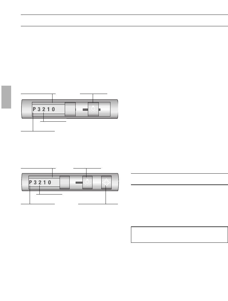
Ne nettoyez les touches de commande
qu'avec de l'eau additionnée d'un peu de
produit à vaisselle. Utilisez un chiffon doux et
humide.
N'utilisez jamais de détergent pour acier pour
nettoyer les touches de commande.
Surfaces en acier inox:
Veuillez utiliser un produit pour l'acier inox
qui le nettoie sans le rayer.
Frottez toujours l'acier inox dans le sens
de son polissage.
Ne nettoyez jamais les surfaces en acier
inox avec des éponges à dos
récurant, et pas non plus avec des déter-
gents à base de sable, soude caustique, aci-
de ou chlore.
Surfaces en aluminium et en plastique:
Utilisez un chiffon doux, ne peluchant pas,
du genre employé pour nettoyer les vitres,
ou un chiffon à microfibres.
N'utilisez pas de chiffons secs.
Utilisez un produit pour vitres mais non
aggressif.
N'utilisez pas de détergents aggressifs,
contenant un acide ou une base.
N'utilisez pas de produits récurants.
4. Réencrantez l'anneau de l'ampoule.
5. Pour remettre la hotte sous tension,
rebranchez la fiche mâle dans la prise de
courant ou remontez le fusible/réarmez
le disjoncteur.
Remarque: si l'éclairage ne fonctionne
pas, contrôlez si les ampoules sont
correctement enfoncées.
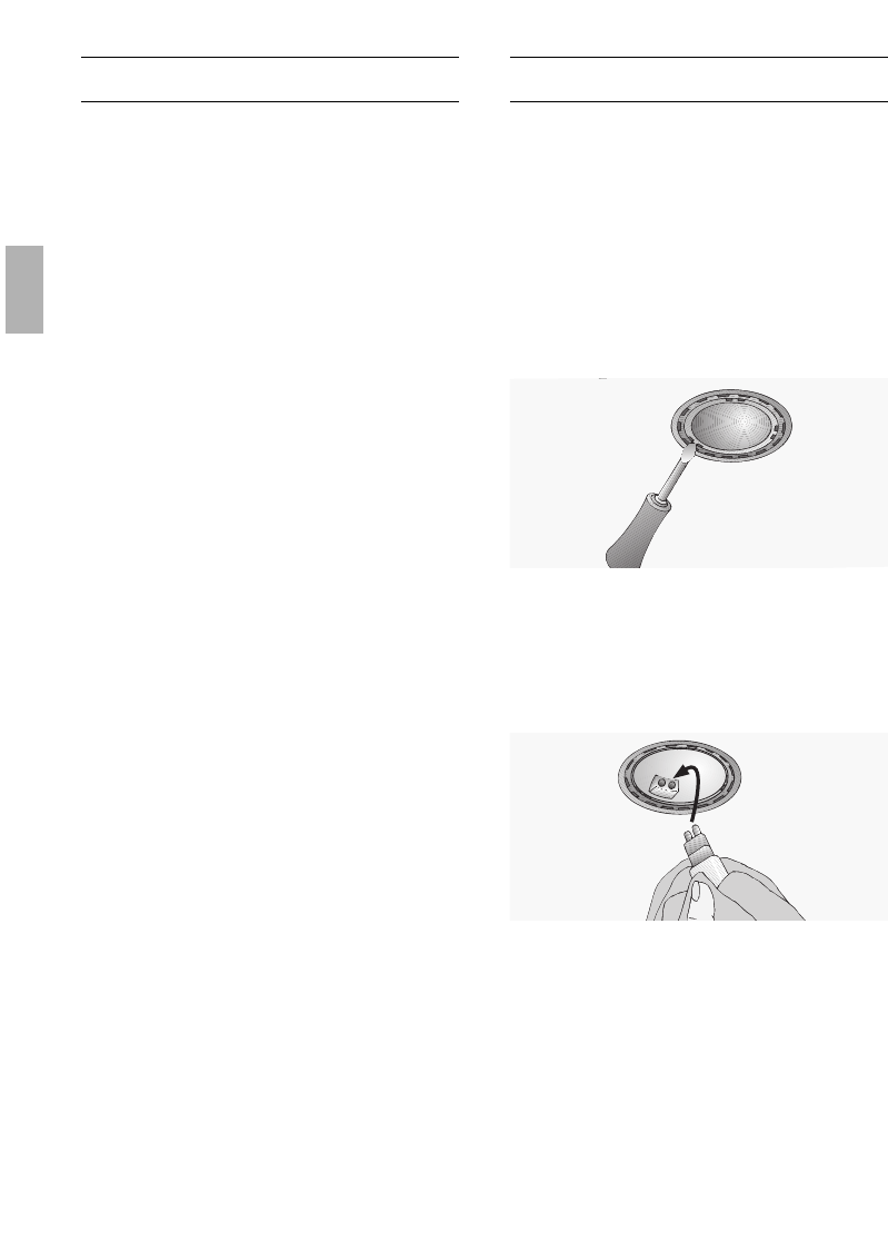
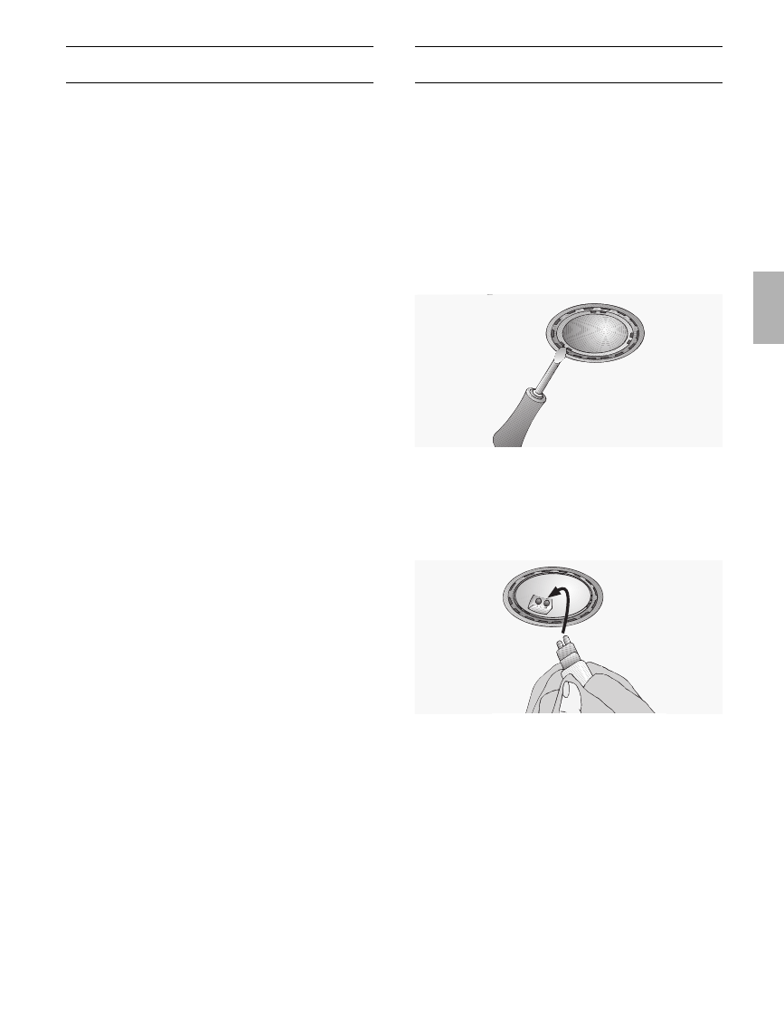
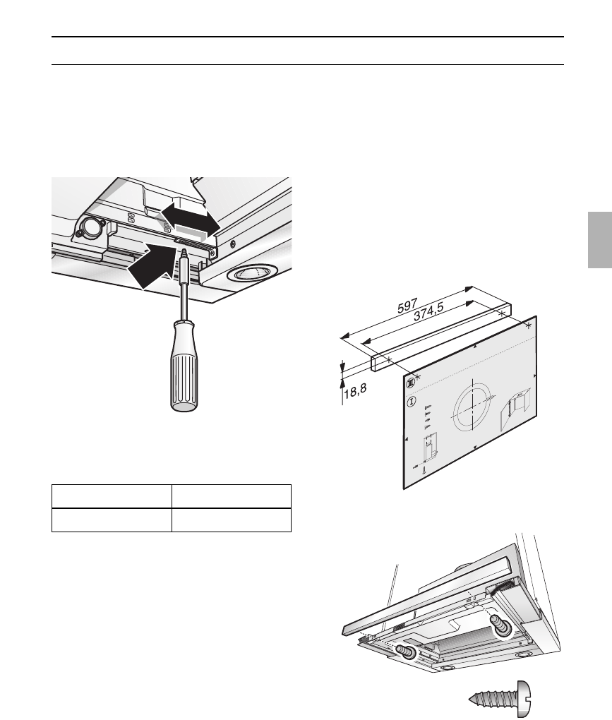
Changer les ampoules halogènes
1. Avant tout nettoyage et entretien, mettez
d'abord la hotte hors tension en
débranchant la fiche mâle de la prise de
courant ou en coupant le isjoncteur/
fusible.
Les ampoules halogènes allumées
deviennent très chaudes. Le risque de vous
brûler demeure, même un moment après
les avoir éteintes.
2. Retirez l'anneau de l'ampoule avec un
tournevis ou assimilé.
3. Changez l'ampoule halogène
(ampoule halogène en vente
habituelle dans le commerce,
12 volts, 20 watts maxi., douille G4).
Attention: douille à enfichage.
Ne saisissez l'ampoule qu'avec un
chiffon propre.
35
Remarques importantes
Notice de montage:
Le montage de la hotte aspirante à la
distance minimum de 650 mm au-dessus
de foyers au gaz – voir fig. 1 – n'est admis
que si les charges thermiques nominales ci-
dessous ne sont pas dépassées:
Cuisinières à gaz
Charge thermique d'un
foyer 3,0 kW maxi.
Charge thermique de tous
les foyers 8,3 kW maxi.
Charge thermique du four 3,9 kW maxi.
Tables de cuisson au gaz
Charge thermique d'un
foyer 3,9 kW maxi.
Charge thermique de tous
les foyers 11,3 kW maxi.
Tables de cuisson vitrocéramique au
gaz
Les charges thermiques nominales
indiquées ci-dessus ne valent pas pour
les tables de cuisson uniformément en
vitrocéramique. Veuillez impérativement
respecter les indications publiées par le
fabricant de la table de cuisson
vitrocéramique.
Cuisinières à combustible solide
Les charges thermiques nominales
maximales et la distance minimum à
respecter valent comme pour les
cuisinières à gaz.
Au-dessus d'un foyer à combustible
solide générateur d'un risque d'incendie (par
projection d'étincelles par ex.), le
montage de la hotte ne sera admis que si ce
foyer est équipé d'un couvercle fermé et
inamovible et si le montage ne
contrevient pas à la réglementation
nationale. Cette restriction ne vaut pas pour
les cuisinières à gaz et les foyers aux gaz.
Plus l'écart est faible entre la hotte
aspirante et les foyers et plus il se pourra
que la vapeur montant des casseroles se
condense et forme des gouttes sur la face
inférieure de la hotte.
Les anciens appareils ne sont pas des
déchets sans valeur.
Leur élimination respectueuse de
l'environnement permet de récupérer de
précieuses matières premières.
Avant de vous débarrasser de l'appareil,
rendez-le inutilisable.
Pour vous parvenir en parfait état, votre
nouvel appareil a été conditionné dans un
emballage qui le protège efficacement.
Tous les matériaux d'emballage utilisés
sont compatibles avec l'environnement et
recyclables. Aidez-nous à éliminer
l'emballage en respectant l'environnement.
Demandez à votre revendeur ou à votre
mairie quelles sont les formes de recyclage
actuellement possibles.
Cette hotte peut évacuer l'air à
l'extérieur ou le recycler.
Fixez toujours la hotte bien centrée
au-dessus des foyers de la table de
cuisson.
L'écart minimum entre les foyers
électriques et le bord inférieur de la hotte
doit être de 430 mm, voir fig. 1.
Remarques supplémentaires
concernant les cuisinières à gaz:
Lors du montage de foyers gaz, veuillez
respecter les dispositions légales en
vigueur dans votre pays (En Allemagne par
ex: les Règles technique TRGI régissant
l'installation du gaz).
Respectez les prescriptions et
consignes d'encastrement en leur version
applicable publiées par les fabricants
d'appareils au gaz.
La hotte aspirante ne pourra cotoyer
que sur un côté un meuble haut ou une
paroi haute. Ecart minimum: 300 mm.
36
L'air vicié est évacué vers le haut par un
conduit d'aération ou directement à l'air
libre par traversée du mur extérieur.
D
L'air vicié ne doit jamais être évacué
vers une cheminée en service, rejetant des
fumées ou des gaz de combustion, ni vers
un conduit servant à l'aération de locaux
dans lesquels se trouvent des foyers à
combustibles solides, liquides et gazeux.
Le mode d'évacuation de l'air vicié
devra être conforme aux arrêtés
municipaux, préfectoraux, et aux
prescriptions légales (par ex. aux
ordonnances publiques applicables au
bâtiment).
Si l'air vicié doit être évacué par des
cheminées d'évacuation des fumées et gaz
de combustion qui ne sont pas en service,
veuillez respecter la réglementation locale et
nationale applicable.
D
Si la hotte évacue l'air à l'extérieur et
si le logement comporte des moyens de
chauffage (tels par ex. des appareils de
chauffage au gaz, au fuel ou au charbon,
chauffe-eau instantanés ou à accumulation)
raccordés à une cheminée, veiller
impérativement à ce que l'apport d'air
soit suffisant pour assurer la marche du
chauffage à combustion.
Un fonctionnement sans risque est possible
si la dépression dans le local où le foyer de
chauffage est implanté ne dépasse pas 4
Pascals (0,04 mbars).
On y parvient en présence d'ouvertures non
obturables ménagées par ex. dans les por-
tes, fenêtres et en association avec des
ventouses télescopiques d'admission/
évacuation de l'air à travers la maçonnerie
ou par d'autres mesures techniques telles
qu'un verrouillage réciproque ou assimilé
permettant à l'air d'affluer pour assurer la
combustion.
En cas d'afflux d'air insuffisant, risque
d'intoxication par réaspiration des gaz
de combustion.
La présence d'une ventouse télescopique
d'apport et d'évacuation d'air ne suffit pas
à assurer le respect de la valeur limite.
Remarque: lors de l'évaluation de la
situation, toujours tenir compte de
l'ensemble des moyens d'aération du
logement. Cette règle ne vaut généralement
pas si vous utilisez des appareils de cuisson
(table de cuisson et cuisinière à gaz).
Si la hotte recycle l'air aspiré au moyen
d'un filtre au charbon actif, son
fonctionnement ne s'assortit d'aucune
restriction.
Si la hotte évacue l'air à l'extérieur,
incorporer un volet anti-refoulement s'il n'y
en a pas déjà un dans le conduit
d'évacuation ou dans la ventouse
télescopique.
Si l'appareil a été fourni sans volet
anti-refoulement, vous pouvez vous le
procurer dans le commerce spécialisé.
Si l'air vicié traverse le mur extérieur,
utilisez une ventouse télescopique.
Avant le montage
Evacuation de l'air à l'extérieur
37
Avant le montage
Pour que la hotte aspirante ait le
meilleur rendement, veillez à ce que:
Le conduit d'évacuation soit court et lisse.
Il ait le moins possible de coudes.
Utilisez des conduits du plus grand
diamètre possible (150 mm ø de
préférence) ainsi que des coudes de fort
diamètre.
L'emploi de conduits d'air vicié
longs, rugueux, formant de nombreux
coudes ou d'un trop petit diamètre
fait descendre le débit d'air en
dessous du débit optimal, tout en
accroissant le bruit d'aspiration.
Conduits ronds
Conduit d’aspiration court:
Diamètre inférieur, 120 mm minimum,
Conduit d’aspiration long:
Diamètre inférieur, 150 mm minimum.
Les conduits plats doivent avoir une
section intérieure équivalente au
diamètre intérieur des conduits ronds.
Les conduits ne doivent comporter
aucun coude prononcé.
l 120 mm = env. 113 cm
2
de section
l 150 mm = env. 177 cm
2
de section
Si les conduits ont des diamètres
différents: utilisez du ruban adhésif à
étancher.
Si la hotte évacue l'air à l'extérieur,
veillez à ce que l'apport d'air soit
suffisant.
Air vicié évacué directement vers
l'arrière:
Ce mode d'évacuation n'est possible qu'à
l'intérieur de placards en appui mural
suffisamment hauts, et suivant la taille du
conduit d'évacuation.
Pour ce faire, ménagez un orifice
circulaire dans la paroi arrière du placard
en appui mural. Dans la circonférence
de l'orifice, prévoyez une entaille par
laquelle passera le câble d'alimentation
électrique.
Air vicié évacué vers le haut:
Vous pouvez vous
procurer le kit de mon-
tage complet auprès
de votre revendeur
spécialisé.
Vous trouverez les
numéros de référence
des accessoires
correspondants dans
la présente notice
d'utilisation.
1. Pour ce faire, ménagez un orifice circulai-
re dans le plafond du placard en appui
mural. Dans la circonférence de l'orifice,
prévoyez une entaille par laquelle passera
le câble d'alimentation électrique.
– Gabarit
O
I accompagnant l'appareil –.
2. Si le placard en appui mural présente un
"plancher", découpez-le sur toute sa
largeur et jusqu'à 270 mm de profondeur.
Branchement d'un conduit à air vicié
de l 150 mm:
Fixez le conduit d'évacuation
directement contre le manchon d'air
vicié.
Branchement du tuyau d'air évacué:
Fixez le manchon réducteur ci-joint
contre l'orifice de sortie d'air.
Il faut étancher les trous situés au niveau
de l'orifice de sortie d'air.
Fixez le tuyau d'air évacué contre le
manchon réducteur.
Mode Air recyclé
Avec filtre à charbon actif, lorsqu'il n'est
pas possible d'évacuer l'air aspiré par la
hotte.
6
0
0
m
in. 293
287
313
195
min.
435
Ø133/170
270
38
Préparation du placard en appui mural
Cette hotte aspirante a été prévue pour
être encastrée dans un placard en appui
mural faisant les dimensions suivantes:
Largeur: 600 mm
Profondeur: entre 293 et 350 mm
Hauteur: 435 mm minimum.
Si le placard fait plus de 293 mm de
profondeur, vous pouvez reculer la hotte
aspirante pour permettre par ex.
l'installation d'un présentoir à épices
devant la hotte.
Pour ce faire, appliquez le gabarit
O
II de
façon correspondante plus en arrière.
La stabilité du placard doit être assurée
pendant et après le montage. Cet impératif
vaut également si l'incorporation de la hotte
a lieu àl'extrémité d'un alignement de
placards.
1. Sur les côtés intérieurs du placard,
marquez les emplacements de quatre
points de fixation: 2 à droite et 2 à
gauche. Amorcez les trous au pointeau.
Percement des trous:
Les trous doivent faire 2 mm de ø et
être profonds de 10 mm maxi.
Pour marquer les emplacements des
points de fixation, utilisez le gabarit
O
II
accompagnant l'appareil.
2. Vissez les deux plaques de fixation.
3. Accrochez le placard avec sa porte puis
ajustez-le par rapport aux autres
placards.
Veillez à ce que la distance minimum
prescrite entre la hotte aspirante et les
foyers soit respectée. Fig. 1.
11


Need help? Post your question in this forum.

Forumrules


Report abuse

Libble takes abuse of its services very seriously. We're committed to dealing with such abuse according to the laws in your country of residence. When you submit a report, we'll investigate it and take the appropriate action. We'll get back to you only if we require additional details or have more information to share.

Product:

For example, Anti-Semitic content, racist content, or material that could result in a violent physical act.

For example, a credit card number, a personal identification number, or an unlisted home address. Note that email addresses and full names are not considered private information.

Forumrules

To achieve meaningful questions, we apply the following rules:

Register

Register getting emails for Siemens LI 46631 at:


You will receive an email to register for one or both of the options.


Get your user manual by e-mail

Enter your email address to receive the manual of Siemens LI 46631 in the language / languages: English, German, Dutch, French, Italian, Portuguese, Spanish as an attachment in your email.

The manual is 14,17 mb in size.


You will receive the manual in your email within minutes. If you have not received an email, then probably have entered the wrong email address or your mailbox is too full. In addition, it may be that your ISP may have a maximum size for emails to receive.

The manual is sent by email. Check your email

If you have not received an email with the manual within fifteen minutes, it may be that you have a entered a wrong email address or that your ISP has set a maximum size to receive email that is smaller than the size of the manual.

The email address you have provided is not correct.

Please check the email address and correct it.

Your question is posted on this page

Would you like to receive an email when new answers and questions are posted? Please enter your email address.


Info