753105
48
Zoom out
Zoom in
Previous page
1/100
Next page
N
L
PE
230V 1N ~ 50Hz
16A
3
L N U1 N
3
N L
r rww
r w
3 4
w
rbb
bb
2
max. 200W
U2 N
3
max. 200W
N L
3
4 Collegamento elettrico
Assicurarsi che i cavi di collegamento posino perfettamente nei morsetti.
I cavi non correttamente fi ssati si surriscaldano e possono causare danni irreparabili e pericolo di incendio.
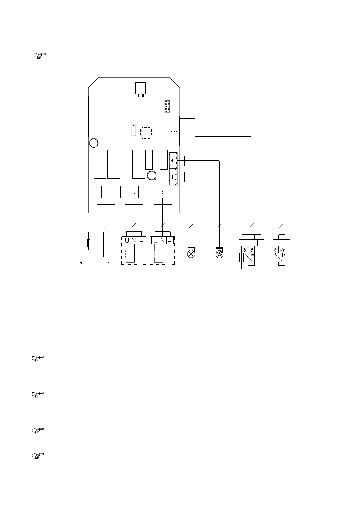
Fig. 5 - Collegamento elettrico
Impianto termico 1 Illuminazione
Sensore temperatura
Sensore a membrana
Rete
Far passare i cavi del sensore attraverso il passaggio nel centro del coperchio. In nessun caso i fi li del
sensore dovranno passare attraverso le aperture applicate nella parte inferiore.
La linea di alimentazione e le uscite per l‘impianto termico e di illuminazione vengono condotte attraverso la
parte inferiore dell‘alloggiamento.
Collegare i cavi al dispositivo di comando come da fi gura 5.
Ricollegare i dispositivi di arresto allentati al punto 3.3.
Avvertenza per il sensore di temperatura: i morsetti contrassegnati con una „r“ sono provvisti di un
ponte. Rimuovere il ponte solo in caso di collegamento di un sensore di temperatura dotato di limitatore
di temperatura di sicurezza. Il sensore fornito in dotazione non è dotato di limitatore di temperatura di
sicurezza.
Avvertenza per il sensore a membrana: il sensore a membrana è solo necessario per il funzionamento
di membrane a raggi infrarossi e piastre di calore a raggi infrarossi. Il sensore a membrana è disponibile
come accessorio. Se si utilizza il dispositivo di comando con membrane o piastre a raggi infrarossi, la
temperatura massima della cabina sarà limitata a 50°C.
Avvertenza per il sensore a membrana: i morsetti br-br sono provvisti di fabbrica di una resistenza.
Rimuoverla in caso di collegamento di un sensore a membrana.
Avvertenza: se si avvia il dispositivo di comando attraverso un segnale esterno (avvio remoto),
si prega di osservare le istruzioni riportate al punto 8 - Avvio remoto
Impianto termico 2
Ventilatore
Istruzioni per il montaggio solo per personale specializzato P. 6/14
WE DO IT FIRST.
48


Need help? Post your question in this forum.

Forumrules


Report abuse

Libble takes abuse of its services very seriously. We're committed to dealing with such abuse according to the laws in your country of residence. When you submit a report, we'll investigate it and take the appropriate action. We'll get back to you only if we require additional details or have more information to share.

Product:

For example, Anti-Semitic content, racist content, or material that could result in a violent physical act.

For example, a credit card number, a personal identification number, or an unlisted home address. Note that email addresses and full names are not considered private information.

Forumrules

To achieve meaningful questions, we apply the following rules:

Register

Register getting emails for Sentiotec IS2 at:


You will receive an email to register for one or both of the options.


Get your user manual by e-mail

Enter your email address to receive the manual of Sentiotec IS2 in the language / languages: English, German, Dutch, French, Italian, Swedish as an attachment in your email.

The manual is 4,21 mb in size.


You will receive the manual in your email within minutes. If you have not received an email, then probably have entered the wrong email address or your mailbox is too full. In addition, it may be that your ISP may have a maximum size for emails to receive.

The manual is sent by email. Check your email

If you have not received an email with the manual within fifteen minutes, it may be that you have a entered a wrong email address or that your ISP has set a maximum size to receive email that is smaller than the size of the manual.

The email address you have provided is not correct.

Please check the email address and correct it.

Your question is posted on this page

Would you like to receive an email when new answers and questions are posted? Please enter your email address.


Info