ANSCHLUSS DES PROJEKTORS
14
An diesen Buchsen liegen die Informationen über die eingestellte Programmquelle an, die auf dem Bildschirm
wiedergegeben werden (Computer 1, Computer 2, Video 1 oder Video 2). Falls Sie als Programmquelle
Computer 2 eingestellt haben, so liegt das an der Computeraudioeingangsbuchse 2 angeschlossene
Audiosignal an den Audiomonitorausgangsbuchsen an.
Verwenden Sie RCA-Audiokabel für den Anschluß.
● Falls der Audioeingang vom Audiogerät in Stereo ist, müssen die Kanäle richtig an der rechten und linken
Buchse angeschlossen werden.
● Falls der Audioeingang des Audiogerätes in Mono ist, so müssen Sie die linke Buchse verwenden.
An dieser Buchse liegen die Informationen über die eingestellte Programmquelle an, die auf dem Bildschirm
wiedergegeben werden (Computer 1 oder Computer 2). Beim Einstellen einer Videoquelle (Video 1 oder Video
2) liegen an dieser Buchse die Informationen von Computer 1 an.
Ein externer Monitor kann an der 15-poligen HDB-Buchse (VGA) des Projektors angeschlossen werden.
● Schließen Sie den Monitor mit dem VGA-Kabel (nicht mitgeliefert) an dieser Buchse an.
■ Serieller Anschluß
9POLIGE
BUCHSE DB
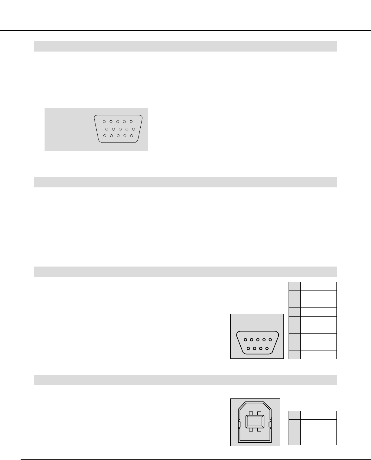
■ USB-Anschluß
15POLIGE
BUCHSE HDB
Anschluß an der Monitorausgangsbuchse (ANALOG HDB, 15-polig)
Anschluß an den Audiomonitorausgangsbuchsen (AUDIO OUT, R und L)
Anschluß am seriellen Anschluß (SERIAL PORT, DB, 9-polig)
Anschluß am UBS-Anschluß 1 und 2 (UBS 1 und 2)
● Für die Steuerung des Projektors mit einem Computer,
müssen Sie ein Kabel (nicht mitgeliefert) vom Computer an
dieser Buchse anschließen.
Dieser Anschluß wird sowohl für die Steuerung des Projektors
mit dem Computer als auch für die Bedienung des Computers
mit der Fernbedienung dieses Projektors verwendet. (Siehe
Seite 49 und 50.)
Verbinden Sie den USB-Anschluß des Computers mit diesem
Anschluß.
Stift/Signal
1 Eingang rot
2 Eingang grün
3 Eingang blau
4 Sensor 2
5 Masse
(Horizontalsynchronisation)
6 Masse (rot)
7 Masse (grün)
8 Masse (blau)
Stift/Signal
9 Nicht verwendet
10 Masse
(Vertikalsynchronisation)
11 Sensor 0
12 Sensor 1
13 Horizontalsynchronisation
14 Vertikalsynchronisation
15 Reserviert
––––––––
R x D
T x D
––––––––
Masse
––––––––
––––––––
––––––––
––––––––
1
2
3
4
5
6
7
8
9
Vcc
Daten –
Daten +
Masse
1
2
3
4