615614
40
Zoom out
Zoom in
Previous page
1/77
Next page
3
ENGLISH
Cool-touch
metal pinkie
switch can be
assigned shift
functionality to
double up on
programmable
commands.
5-position adjustment
to suit all hand sizes.
2-Stage metal trigger
Destroy the enemy with the aid of a
precise and durable, cool-touch trigger.
Two-stages can be programmed with
separate fire functions.
3D Rudder Twist
handle on
joystick for
precise rudder
control; includes
integrated rudder
lock mechanism.
3 toggle switches
Spring loaded and conveniently
positioned on the base for an
extra 6 programmable flight
commands.
Precision centering mechanism
Non-contact technology on x and
y axes and constant spring force
reduce free play, improve control
and increase durability.
3 Fire Buttons
Backlit buttons
conveniently
positioned on
joystick head for
instant access in the
heat of the battle.
Missile Launcher
Flip up the spring-loaded
safety cover to activate
missile launches.
2 x 8-way hat switches
-1 pre-defined as point
of view; select from
multiple view
perspectives and
assign frequently used
commands.
General Features
Backlighting
Illuminated buttons and Multi-Function Display (MFD) - ideal for
low light environments, guaranteed to stand out from the crowd.
Adjust brightness via Windows control panel.
Metal parts
Part metal construction for increased durability and maximum
comfort during extended gameplay.
Mode selector switch
3-position rotary switch with tri-
state LED to indicate program
mode.
SAITEK X52 FLIGHT CONTROL SYSTEM - PRODUCT TOUR
Joystick
X52 manual(ok)(24/11/04) 2004.12.22 9:05 PM Page 3
5
ENGLISH
4
GETTING STARTED
In order for this product to function correctly please install the drivers on the
CD supplied with this product.
INSTALLATION FOR USERS OF WINDOWS¨ XP
A) Drivers Only For Typical Users
1 With your computer switched on, close down any programs that are currently running and insert the Saitek Smart
Technology CD into your CD-ROM drive.
2 When the Introduction Screen appears, click Install Software to continue. If the CD does not run automatically,
select Start from the Windows¨ Taskbar, then Run and type D:\Setup.exe and click OK - where D:\ is the letter of
your CD-ROM drive.
3 When the Welcome screen appears, click Next to continue.
4 After reading the Disclaimer, select the I accept the terms of the Disclaimer option and click Next to continue.
5 At the Driver Setup screen, if you havenÕt already done so, plug in your controller and click on Next.
6 At the Driver Setup screen, click Next to test your controller.
7 When the Saitek Controller screen appears, try out all your controllerÕs buttons and controls to show that it is
working properly. When you have finished, click OK. For more information on the use of the control panel, please
see the Maintaining your Controller Settings section of this manual.
8 At the Software Setup screen, select Do not install the SST Programming Software and click Next. The
Programming Software can be installed at a later date by following instruction (B). below
9 At the Registration screen, select Check this box to register now and follow the on-screen instructions, or you
can choose to select this option later.
10 Click on Finish to complete the installation.
Multi-Function Display (MFD) screen indicates:
Mode and shift state
Mode state is determined by mode selector on the head of the stick.
User defined Text area
- indicates name of command assigned to button when activated.
- supplies name of profile in use and enables on-the-fly profile
selection. Profile can also be changed during gameplay by pressing
clutch button and scrolling though available profiles moving the point-
of-view hat switch up and down. Move the same button left to clear
current profile or right to activate profile.
Multi Time Displays
Time zone (set origin and destination local times in control panel)
Formattable date/month/time
Stopwatch for flight time
Throttle
2 Fire Buttons
Conveniently positioned on
throttle head for instant
access in the heat of the battle.
Progressive throttle control
Super smooth action with metal tension
adjustment and detents for programming idle
(0-20%) and afterburner (80-100%) settings.
Mouse controller,
which can also
function as a hat
switch.
8-way hat switch:
Select from multiple view
perspectives and assign
frequently used commands.
Two rotaries provide axes
for pitch, trim and yaw
settings.
Clutch (I) Button
Initiates 'safe mode' to allow
on-the-fly profile selection,
or to display button
functionality on MFD without
activating commands.
Smooth-action
thumb slider
provides axes for
pitch, trim and
yaw settings or
zoom in/out view.
Scroll wheel positioned on rear
of throttle for index finger
activation; includes built-in
button.
Left mouse button.
X52 manual(ok)(24/11/04) 2004.12.22 9:05 PM Page 4
7
ENGLISH
6
7 When the Controller Properties screen appears, click Next to view the Test screen.
8 Now try out all your controllerÕs buttons and controls to show that it is working properly. When you have finished, click
OK.
9 At the Programming Software screen, select Typical User and click Next.
10 At the Registration screen, select Register and follow the on-screen instructions or select Register Later and click
Next.
11 Click on Finish to complete the installation.
B) Drivers and Programming Software For Advanced Users
1 Follow points 1 Ð 8 of the install procedure in A), then at the Programming Software screen, select Advanced User
and click Next.
2 At the Programmable Controller Drivers screen, click Update and follow the on-screen instructions.
3 Then at the Installation of programming software successful screen, click Next.
4 At the Registration screen, select Register and follow the on-screen instructions or select Register Later and click
Next.
5 Upon completion of the installation, you have the option to Run Profile Editor, which will give you a view of the 3D
programming environment. If you do not wish to see the Profile Editor at this point, just uncheck the box and click on
Finish to complete the installation.
INSTALLATION FOR USERS OF WINDOWS¨ 98 AND ME
A) Drivers Only For Typical Users
1 With your computer switched on, close down any programs that are currently running and insert the Saitek Smart
Technology CD into your CD-ROM drive.
2 When the Introduction Screen appears, click Install Software to continue. If the CD does not run automatically, select
Start from the Windows¨ Taskbar, then Run and type D:\Setup.exe (where D: is your CD drive) and click OK.
3 When the Welcome screen appears, click Next to continue.
4 After reading and accepting the Disclaimer, click Next to continue.
Note: For your controller to work, you must have a minimum of Microsoft¨ DirectX¨ 8.1 installed on your computer. The
B) Drivers and Programming Software For Advanced Users
1 Follow points 1 Ð 7 of the install procedure in A), then at the Software Setup screen, select Install the SST
Programming Software and click Next.
2 In the following Software Setup screen, click Next and follow the on-screen instructions. At this point you will be
asked to install such features as the Saitek Magic Mouse, HID-compliant mouse, Saitek Magic Keyboard and
HID Keyboard Device (these are what XP calls the various elements of your Saitek controller). Continue to click on
Next and Finish to accept the installation until the Registration screen appears.
3 At the Registration screen, select Check this box to register now and follow the on-screen instructions, or do not
select this option and register later.
4 Upon completion of the installation, you have the option to Run Profile Editor, which will give you a view of the 3D
programming environment. If you do not wish to see the Profile Editor at this point, just uncheck the box and click on
Finish to complete the installation.
INSTALLATION FOR USERS OF WINDOWS¨ 2000
A) Drivers Only For Typical Users
1 With your computer switched on, close down any programs that are currently running and insert the Saitek Smart
Technology CD into your CD-ROM drive.
2 When the Introduction Screen appears, click Install Software to continue. If the CD does not run automatically,
select Start from the Windows¨ Taskbar, then Run and type D:\Setup.exe and click OK - where D:\ is letter of your
CD-ROM drive.
3 When the Welcome screen appears, click Next to continue.
4 After reading the Disclaimer, select the I accept the terms of the Disclaimer option and click Next to continue.
5 At the Device Driver Installation screen, click on Next and follow the on-screen instructions.
6 When prompted, plug your controllerÕs USB connector into your computer, then click on Configure.
X52 manual(ok)(24/11/04) 2004.12.22 9:05 PM Page 6
MAINTAINING YOUR CONTROLLER SETTINGS
Your Saitek X52 Flight Control System (FCS) is supplied ready for use. However, we want you to use it in the way that
suits you best. We've therefore included the facility for you to change various settings on your stick and throttle units.You
can, for example, vary the brightness of the LED buttons, check your stick is working correctly or change the way the
date is displayed on your Multi-Functional Display (MFD).
You change your controller settings in the Saitek X52 Flight Stick properties window. There are two ways you can open
this window. Either:
¥ Double-click on the Game Controllers icon in the Control Panel and then click Properties in the Game Controllers
window that is displayed. Or,
¥ If the SST programming software has been installed, right-click on the Saitek X52 Flight Stick profiler icon in your
task bar and select Control Panel from the popup list of options displayed.
The Saitek X52 Flight Stick properties window consists of five separate tabs. You can view and change various controller
settings in each tab. The settings you can change are described in the following sections.
Testing your controller
You can make sure that the various features of your controller are working correctly. You do this in the Test tab of the
Saitek X52 Flight Stick properties window.
To test your controllers, follow the steps below:
9
ENGLISH
8
installer will automatically recognize if this software needs to be added, and will allow you to install it directly from the
Saitek Product Companion CD, if necessary.
If you are asked to install Microsoft¨ DirectX¨ 8.1, click Install and follow the on-screen instructions, and then restart
your computer when prompted. Make sure that you leave the Saitek CD in the drive when restarting. After this
software has been installed, you will automatically be taken to the installation to continue with the next step.
5 Follow the on-screen instructions and select Yes, I want to restart my computer now when prompted.
6 After the restart, at the Device Driver Installation screen, click on Next and follow the on-screen instructions.
7 When prompted, plug your USB connector into your computer.
8 When the Controller Properties screen appears, click Next to view the Test Screen.
9 Now try out all your controller buttons and controls to show that it is working properly. When you have finished, click
OK.
10 At the Programming Software screen, select Typical User and click Next.
11 At the Registration screen, select Register my Saitek controller online, click Next and follow the on-screen
instructions or select Register Later and click Next.
12 Click on Finish to complete the installation.
B) Drivers and Programming Software For Advanced Users
1 Follow points 1 Ð 9 of the install procedure in A), then at the Programming Software screen, select Advanced User
and click Next.
2 At the Programmable Controller Drivers screen, click Update and follow the on-screen instructions. At this point
you will be asked to insert your Windows¨ CD, however, DO NOT do this, just click on OK. At the next screen, type
C:\windows\system into the prompt and click OK and follow the on-screen instructions.
3 At the Installation of programming software successful screen, click Next.
4 At the Registration screen, select Register my Saitek controller online, click Next and follow the on-screen
instructions or select Register Later and click Next.
5 Upon completion of the installation, you have the option to Run Profile Editor, which will give you a view of the 3D
programming environment. If you do not wish to see the Profile Editor at this point, just uncheck the box and click on
Finish to complete the installation.
X52 manual(ok)(24/11/04) 2004.12.22 9:05 PM Page 8
Testing axes
You can test the following axes and controls:
Feature Explanation
X/Y Axes Move the flight stick backwards and forwards or from left to right. The + symbol
moves in the X/Y Axes box, to show the drivers are picking up the stick
movement correctly.
Twist The vertical gray line represents the center point of the flight stick. Rotate the
flight stick clockwise or anti-clockwise. This is the rudder that enables you to
change direction outside the X and Y axes. If the drivers are detecting the
movement correctly a red band is displayed on either side of the center point line.
Throttle Move the throttle up or down to increase or decrease your acceleration. A red
band shows the current rate of acceleration, ranging from 0% (no red) to the
maximum acceleration at 100% (the box is filled with red).
Rotary 1 and 2 Rotate the rotary controls on the throttle unit. These are user-defined via the SST
programming software or within each game. They range from 0% (no red) to 100%
(the box is filled with red). You may, for example, use them to control fuel mixture
or radar gain.
Precision Slide Move the slide control on the throttle unit. This is user-defined via the SST
programming software or within each game, and ranges from 0% (no red)
to 100% (the box is filled with red). You may, for example, use it to control
pitch or fuel mixture.
Testing buttons, toggle and mode switches
You can make sure button presses are being detected by the drivers. Press each button on your flight stick or throttle
unit that you want to test, in turn. The corresponding numbered disc lights up in the Buttons panel of the Test tab.
Note: What each button does depends on the game in progress. You can, if you wish, assign functions to individual
buttons using the SST programming software. See the SST programming software manual for details.
The numbered boxes in the Toggle Switches panel illuminate when you press the toggle switches on your flight stick unit.
The three red boxes in the Mode panel indicate which mode is currently selected. The top box represents mode 1, the
middle box mode 2 and the lower box mode 3. Make sure your mode selector switch is working correctly by rotating the
switch to change modes. The corresponding box in the Mode panel illuminates.
11
ENGLISH
1 Click the Test tab.
The controller features that you can test are displayed below.
2 Test each feature as required.
The way you do this varies, depending on what the feature does. It may, for example, involve pressing the
corresponding button, or turning the corresponding rotary control.
The features you can test are explained in the following sections.
10
X52 manual(ok)(24/11/04) 2004.12.22 9:05 PM Page 10
To maintain your deadzones
1 Click the Deadzone tab.
The controls you can create deadzones for are
shown, as follows:
Each axis is represented by a white box that contains
a red line that represents where the control is
currently sitting. Moving the corresponding control
moves the red line. Use this line to determine exactly
where your deadzone must begin and end. Beneath
each box is a sliding scale. You use this to specify the
size of each deadzone.
2 Click on a slider on the sliding scale and drag it
to where you want the deadzone to end. The
area that represents the deadzone is shaded
gray.
3 Use the center sliders to maintain the deadzone
around the center point of an axis. Use the
sliders at either end to create deadzones at
either end of the axis.
Tips: By default, clicking on either the right or the left
slider in the pair moves both sliders. You can change
this if you just want to adjust one side of the deadzone. To do this, right-click anywhere in the white box and select Link
Deadzones from the popup list of options displayed. Repeat this to link the pairs of sliders again.
You can clear existing deadzones for an axis by right-clicking anywhere in the white box and selecting Clear Deadzone.
You can maintain deadzones for the following features of the Saitek X52 FCS:
13
ENGLISH
Testing POVs
Moving the POV controls on your flight stick in the various directions should illuminate the corresponding direction arrows
in the POV panel. POV 1 is used to look around the cockpit. POV 2 can be configured to trigger four or eight different
functions of your choice. See the SST programming software manual for details.
You can also make sure that movements of the Throttle Hat control cause the corresponding direction arrows in the POV
panel to illuminate. As for POV 2, the throttle hat control can be configured to trigger four or eight different functions of
your choice.
Testing the ministick
The ministick on the throttle unit is used to perform actions you would otherwise use your mouse for. Moving the
ministick moves the + symbol in the Mouse X/Mouse Y box.
Maintaining deadzones
You can create deadzones for each range and axis your controller features move in. They reduce interference that may
be caused by unintended movements of the flight stick and other controls. For example, you may want to move your
stick in the X axis only, but find it difficult to avoid moving it in the Y axis as you do so. You can set up a deadzone in the
Y axis so that these minor movements are not detected by the drivers.
What is a deadzone?
A deadzone is a part of the range in which an axis moves that is not detected by the drivers and so has no effect on the
game in progress. It may be around the center point of the range, or at either end.
12
X52 manual(ok)(24/11/04) 2004.12.22 9:05 PM Page 12
Maintaining your LED brightness
The authenticity of the flight control experience
provided by your Saitek X52 FCS is enhanced by a
number of LEDs on the throttle unit and flight stick.
You can control the appearance of these LEDs,
making them brighter or dimmer according to your
preference.
15
ENGLISH
Feature Explanation
X Axis Movements of the stick from left to right or right to left.
Y Axis Movements of the stick from back to front or front to back.
Twist Rotations of the stick clockwise and anti-clockwise.
Throttle Movements of the throttle to increase or decrease your speed.
Rotary 1 Rotations of the small rotary control on the throttle.
Rotary 2 Rotations of the large rotary control on the throttle.
Precision Slide Movements of the slide
control on the throttle.
14
X52 manual(ok)(24/11/04) 2004.12.22 9:05 PM Page 14
To change the brightness of your MFD
1 Click the MFD tab.
A Brightness sliding scale is displayed at the top of the tab.
2 Change the brightness of your MFD by moving the slider along the scale. To move the slider, you can either:
¥ Click and drag the slider along the scale. Or:
¥ Click a point on the scale itself, to move the slider in graduated steps along the scale.
The brightness of your MFD changes as you move the slider. Use this to determine when the slider is in the right place.
Maintaining clock settings
Your MFD can display the current time in any time zone. You can choose the time zones displayed and the format in
which the time for each zone is displayed.
You can have up to three different time zones available on your MFD. Greenwich Mean Time (GMT) is included by
default. You can choose up to two additional time zones. When using your MFD, you switch between the three time
zones, as required.
To change your clock settings
1 Click the MFD tab.
This tab includes three panels in which you change the way time is displayed on your MFD. They are called Clock 1,
Clock 2 and Clock 3.
Note: Clock 1 is set to GMT by default. You cannot change this.
2 Choose additional time zones that you want to be able to view on your MFD in the Clock 2 and Clock 3 panels. You
do this by selecting an option from the corresponding Time Adjustment drop-down list.
Each option is a time relative to GMT, for example GMT +1:00 is GMT plus one hour, and so on. Each time is also
represented by an entry in the phonetic alphabet. For example, GMT is represented by 'Zulu' and GMT +12:00 by
'Mike'.
3 Choose the format you want each time to be displayed in. To do this, either check or uncheck the corresponding 12
Hour Format checkbox.
When the box is unchecked, the time is displayed in 24 hour clock format, i.e. between 00:00 and 23:59. If it is
checked, the time is shown in 12 hour clock format.
4 Click Apply.
You can now view the current times in your chosen time zones on your MFD. See Using the MFD for details.
17
ENGLISH
To maintain LED brightness
1 Click the LEDs tab.
A sliding scale is displayed, which you can use to choose how brightly the LEDs on your stick and throttle are
displayed:
2 Move the slider on the scale to adjust LED brightness. The LEDs change as you move the slider, so you can make
sure they are as you want them to be. You can either:
¥ Click and drag the slider along the scale. Or:
¥ Click a point on the scale itself, to move the
slider in graduated steps along the scale.
Maintaining MFD settings
Your Saitek X52 FCS flight stick unit includes an
MFD, or Multi-Functional Display. You can control the
way information is displayed in your MFD by
changing various settings in the MFD tab:
What is the MFD?
The MFD is a screen that displays a variety of
different information including, for example, the mode
currently selected and today's date. It is part of the
same unit as your throttle. The MFD itself and the
way it works is explained in more detail in Using the
MFD.
16
X52 manual(ok)(24/11/04) 2004.12.22 9:05 PM Page 16
of the driver and software versions that you currently have installed.
To view this information, click the About tab. This tab is shown above:
Using the MFD
The MFD, or Multi-Functional Display, is an integral part of your throttle unit. It displays a variety of information including
button names, the current profile and today's date. It also provides a stopwatch feature.
You can change some of the settings that determine the way your MFD works. For example, you may want to increase
the brightness of the display, or change the way the date is shown.
You do this in the MFD tab of the Saitek X52 Flight Stick Properties
window. See Maintaining MFD settings in the section Maintaining
your controller settings for more information.
Features of the MFD
The MFD is divided into three sections:
¥ The mode section is at the top of the MFD and shows the
currently selected mode. See Working with modes, below.
¥ The center section of the MFD is used to view the names of
buttons on your flight stick and throttle, and to view and change
the current profile. See Working with profile information, below.
¥ The time and date display is at the bottom of the MFD. It can
show the current time in up to three time zones. It also includes
the stopwatch. See Viewing the time and date and Using the
stopwatch, below.
The layout of the MFD is shown right:
The three buttons beneath the MFD are used to change the time
display and to operate the stopwatch.
Working with modes
The Saitek X52 FCS offers extensive opportunities for you to
configure your controller to work the way you want it to. You do this
by creating profiles, using the SST programming software. (See the
SST programming software manual for details.) Within each profile,
19
ENGLISH
18
Maintaining date settings
The current date is displayed in the bottom right-hand corner of your MFD. You can choose how this date is displayed.
You may, for example, prefer to see the month first, followed by day and year.
To change your date settings
1 Click the MFD tab.
The format the date is currently displayed in on your MFD is shown in the Date Settings panel.
2 Select the format you want the date to be displayed in from the drop-down list.
3 Click Apply.
Changing the way your clutch button works
The clutch button on your throttle is used to temporarily
deactivate the buttons in the game in progress. This enables
you to check what each button does without interrupting the
game, and to select a different profile if required. See Viewing
button names in Using the MFD for more information.
To change the way your clutch works, check or uncheck the
Latched Clutch Button checkbox in the Clutch Settings panel
and then click Apply.
When the box is checked, pressing and releasing the clutch
deactivates the buttons in the game in progress. To re-
activate the buttons, you must press and release the clutch
again.
When the box is unchecked, the buttons are deactivated in
the game only as long as the clutch is depressed. When you
release the clutch, pressing buttons once again affects the
game in progress.
Viewing notes and version information
Useful information about the SST programming software,
along with a link by which you can download the latest
version of the software, is provided. You can also view details
X52 manual(ok)(24/11/04) 2004.12.22 9:05 PM Page 18
If you have selected one of the three pinkie modes
described above, the word SHIFT is displayed,
because the pinkie switch is acting as a Shift key.
Working with profile information
You can use the center section of the MFD to view the
names assigned to buttons on your flight stick and
throttle. It also shows the names of the profile and
mode currently selected.
Viewing button names
You can view the names assigned to buttons in the
current mode. You may use the SST programming software to create a number of profiles. Each profile may include up
to six different modes, assigning different functions to individual buttons for use in different games.
If you've created profiles, you can view the names you've given to buttons in the selected mode in the current profile. If
not, the standard name assigned to each button is displayed. The standard name reflects the function assigned to each
button when your Saitek X52 FCS is supplied.
21
ENGLISH
you can create up to six different modes that determine the actions performed when you press buttons on the flight stick
and throttle.
You can use your MFD to view the mode that is currently selected.
Changing the mode
You change the mode by rotating the mode selector switch on your flight stick. As you do this, the MODE number
displayed on the MFD changes to reflect your selection.
Using additional modes
Three modes are available by default. You can increase this to six using the pinkie switch on your flight stick. To do this
you must designate the pinkie switch to perform the same function as the Shift key, using the SST programming
software. You can then select one of the additional modes by holding down the pinkie switch as you rotate the mode
selector switch. When you do this, the word SHIFT is displayed in the mode section of your MFD.
Within each profile, you can use the following modes:
¥ Mode 1
¥ Mode 2
¥ Mode 3
¥ Mode 1 + Pinkie
¥ Mode 2 + Pinkie
¥ Mode 3 + Pinkie
Viewing the current modeThe mode that is currently selected is displayed in the top part of the MFD. This is shown in the following example:
20
X52 manual(ok)(24/11/04) 2004.12.22 9:05 PM Page 20
4 Release the clutch. The way you do this depends on your clutch settings. Either stop pressing the clutch button or press
and release it.
Viewing the time and date
The lower part of the MFD displays the current time and date:
This part of the MFD can also be used as a stopwatch. You toggle between the two features by pressing the Function
button. See Using the stopwatch, below, for more information about this feature.
Viewing the time
You can choose the time zone for which the current time is displayed from up to three available time zones. To move
between the available time zones, press the up (Start/Stop) and down (Reset) buttons.
As you move between the three time zones, a number is displayed in the bottom right corner of the MFD (in place of the
date). This number disappears after a few seconds.
Greenwich Mean Time (GMT) is available by default, and is represented by the number 1. You can choose which other time
zones are available and the format in which each time is displayed. See Maintaining clock settings in the section Maintaining
your controller settings for an explanation of this procedure.
Viewing the dateThe date is displayed in the bottom right-hand corner of the MFD. By default, it is shown in the format
MMDDYY. You can change the date format, for example to DDMMYY. See Maintaining date settings in the section
Maintaining your controller settings for an explanation of this procedure.
Using the stopwatch
The lower part of the MFD can also be used as a stopwatch. You
toggle between the stopwatch and time displays by pressing the
Function button. When the stopwatch is selected, the following is
displayed:
To use the stopwatch
1 Press Start/Stop once. The number of seconds begins to
increase.
2 Press Start/Stop again to stop the timer.
3 Press Reset to clear the time and return to 00:00.
23
ENGLISH
To view the name of a button, press it as you normally would. Its name is displayed in the centreline of the MFD.
If a game is in progress, use the clutch to deactivate the buttons in the game. You can then press them and view their
names without affecting the game. When supplied, the clutch is set up so that you must keep it depressed for as long as
you want the buttons to remain inactive in the current game. You can change the way the clutch button works via the
MFD tab of the Saitek X52 Flight Stick properties window. See Changing the way your clutch button works in Maintaining
your controller settings for details.
Note: You cannot view button names if the Saitek X52 Flight Stick properties window is open.
Changing the current profile
You can use the MFD to change the current profile 'on the fly'. You may, for example, realise that you're not working in
the correct profile for the game in progress.
To change the profile on the fly
1 Press the clutch button. The LEDs on your clutch and on the main POV control on your flight stick begin to flash on
and off. Pressing buttons does not affect the game in progress when the clutch is engaged.
Note: When supplied, the clutch is set up so that you must keep it depressed for as long as you want it to be
engaged. You can change the way the clutch works via the MFD tab of the Saitek X52 Flight Stick properties
window. See Changing the way your clutch button works in Maintaining your controller settings for details.
2 Move the main POV control on your flight stick up (north) or down (south) to scroll through your profiles. As you do
this, the profile names are displayed in the bottom row of the centre section of the MFD.
Note: You can use the MFD to access any folder
on your computer. To open a folder, push the POV
to the right (east). To move up a level, scroll
through the files and folders in the current folder
until [É] is displayed, and then push the POV to
the right (east).
3 Select the profile you want by moving the main
POV control right (east) when the profile's name is displayed on the MFD. It becomes the current profile and its
settings are applied when you resume the game in progress.
Tip: You can clear the current profile by moving the POV left (west). The buttons on your stick and throttle return to their
default settings.
22
X52 manual(ok)(24/11/04) 2004.12.22 9:05 PM Page 22
3 Move the screw until the hand rest and pinkie switch are at the height you want.
4 Place the screw in the position that best suits your preferred height. There are five positions for you to choose from.
5 Tighten the screw in position by turning it clockwise.
ROGER WILCO SOFTWARE
Roger Wilco is a "virtual walkie-talkie" that let's you talk to your friends as you play online games.
Highlights
¥ Simple to use
¥ Sound quality is equivalent or better than a CB radio.
¥ Works with hundreds of Windows games.
¥ Support for web integration and ICQ integration (Windows)
¥ Windows Game Developer Tools.
¥ Built-in channel browser to help you find other chatters
Disclaimer:
Roger Wilco is the property of GameSpy Industries and as such Saitek plc accepts no responsibility for this product. Any
queries relating to this product should be directed to GameSpy Industries.
25
ENGLISH
Note: The timer initially shows minutes and seconds. If the time recorded reaches fifty-nine minutes and fifty-nine
seconds, i.e. 59:59, it changes to show hours and minutes. This means the next reading after 59:59 is 01:00.
Using the rudder lock
You can deactivate the rudder feature on your flight stick by engaging the rudder lock. When you do this, the flight stick
no longer rotates.
To use the rudder lock
1 Position your flight stick unit with the three toggle switches (T1 to T6) facing you. The rudder lock can be seen at the
base of the flight stick, on the left hand side. If you look closer, you will see that it is labelled RLOCK.
2 Pull out the RLOCK switch. You may find the easiest way to do this is by using the thumb on your left hand.
The twist action on the flight stick is now locked and you can no longer rotate it.
You can restore the rudder feature at any time by pushing the RLOCK switch back in.
Adjusting the handle
You can optimise your comfort when using the flight stick by adjusting the height of the hand rest and pinkie switch. If
your hands are small, you can place the hand rest and pinkie switch in the highest position available. This reduces the
distance between the trigger switch and pinkie switch, avoiding the need for you to stretch to reach both. If you have
larger hands, you can maximise this distance and operate the flight stick in greater comfort.
To adjust the handle
1 Position your flight stick unit with the three toggle switches (T1 to T6) facing away from you.
A metal screw is clearly visible about one third of the way up the back of the handle.
2 Loosen the screw by turning it anti-clockwise.
When the screw is loose enough, you can move it freely up and down within its slot on the back of the handle.
Moving the screw also moves the hand rest and pinkie switch.
24
X52 manual(ok)(24/11/04) 2004.12.22 9:05 PM Page 24
27
ENGLISH
26
A WORD ON DRIVER UPDATES
From time to time there may be updates to the driver and programming software for this product. You can check for the
latest software updates by visiting the Saitek website and clicking on Downloads. A drop down menu will appear. Select
Drivers and Software.
FOR WINDOWS¨ XP USERS; DYNAMIC UPDATES:
You can check for Driver updates using Windows update. Click on Start on the bottom left hand corner of your monitor
and then select Windows Update from the menu. Click on Driver Updates then select from any of the update options
that appear in the centre of the window. When you have selected the relevant file to download go to the left hand side of
the window and select Review and Install Updates. Finally click on Install Now from the centre section.
If you are using the SST Programming software then you will need to obtain an updated version to work with the new
drivers that you have downloaded from Windows update. To obtain the new version of the software, open the Game
Controllers icon in Control Panel, select the controller in the window and click Properties. At the top of the Properties
window click the About tab and you will see a link that says ÒClick here to download the SST Programming
SoftwareÓ. Click on the link and Windows will give a download prompt asking if you want to open the file or save it.
Choose to save it to your preferred location on your computerÕs hard disk and the file will start downloading. Once the file
has downloaded, find it on your hard disk and double click on it to install the programming software.
ENABLING YOUR CONTROLLER IN GAME
Most games support game controllers, which you can enable by using a [control] options menu within the Main Menu
of the game itself.
If you are having trouble working out how to do this or if you're unsure whether the game being used supports game
controllers, please refer to the user manual for that game for more help.
NOTE: Even if the game you are using does not support game controllers, it is possible to make the controller work in
that game using the Saitek Smart Technology programming software (only installed if you chose to be an Advanced User
when installing). Using the programming software allows you to program your controller with keyboard and mouse
commands, enabling it to work in those games that only have support for keyboards and mice. For help using this
powerful programming software, consult the Programming Your Saitek Controller with Saitek Smart Technology
Programming Software section in this manual.
IMPORTANT INFORMATION
Important notice for Windows¨ XP users
If you have updated Windows XP to Service Pack 2 the following screen will appear when installing the Saitek Magic
Mouse and Keyboard:
At this point we recommend that you select the No, not this time option and then click on Next to carry on with the
installation.
X52 manual(ok)(24/11/04) 2004.12.22 9:05 PM Page 26
29
ENGLISH
28
PROGRAMMING YOUR SAITEK CONTROLLER WITH SAITEK SMART TECHNOLOGY
PROGRAMMING SOFTWARE
Introducing Saitek Smart Technology Programming Software
Saitek Smart Technology Programming Software (SST) is the software Saitek supplies to configure your Saitek controller
for enhanced functionality. SST delivers a powerful set of features, allowing you to program your device with the ultimate
configuration for total interaction. Despite a level of sophistication previously unseen in the market, and because of the
Saitek Smart Technology inside, the software remains simple and intuitive to use.
Features of Smart Technology Programming Software:
¥ Quick and easy setup in any game
¥ Personalize the controller settings for your favorite games
¥ Configure your controller with an on-screen 3D model and interface
¥ Multiple setup option for each controller - ideal if a controller is used by several people
¥ Program special moves with sophisticated timing features
¥ Special game setups available as ÔProfilesÕ from the Saitek website and on the Smart Technology CD
¥ Download the latest version of Saitek Smart Technology software from the Saitek website
What is a Profile?
A Profile is a custom setup for improved gameplay Ð consisting of a set of commands that are pre-assigned to the
buttons or axes of your controller. We have provided some profiles for popular games on the Product Companion CD
that accompanies your device.These profiles should be copied to the C:\Program Files\Saitek\Software directory on your
PC before use.you can then open them from within the Profile Editor software by clicking File>Oper,at the top of the
window;select the profile you wish to edit and then click Open.
How Do I Program My Controller?
After getting to know your controller, you can start creating your own personal Profiles with the Saitek Smart Technology
programming software (SST). This software has virtually unlimited programming capabilities and allows you to customize
the controller to your exact gaming needs.
The Profile Editor allows you to program the buttons on your controller to perform different actions within your games Ð
this is especially useful if the game you are using does not have its own screen that allows reconfiguring of your buttons.
TROUBLESHOOTING
Q My computer is not recognizing the Saitek Controller Ð whatÕs wrong?
A 1. Have you installed the drivers on the CD supplied with this product?
2. Check the cable connections. Unplug your controller and plug it back in, making certain that it is securely
attached.
3. Have you tested your controller? Please refer to the "How to Test Your Controller" section in this manual for
further information
Q2 The game I am playing does not recognize my controller - what's wrong?
A 1. Ensure that you have conducted the checks in Q1 [above]
2. Does the game you are playing offer support for game controllers? Please refer to the "Enabling Your Controller
in Game" section in this manual for further information.
HOW TO TEST YOUR CONTROLLER
¥ You can do this at any time by Clicking on Start, then Settings and selecting Control Panel in Windows (XP users
may only need to click on Start and then Control Panel)
¥ Look for an icon called either Game Controllers or Gaming Options (XP users may have to click Printers and
Other Hardware first).
¥ Open the Game Controllers/Gaming Options window then the name your controller should show up.
¥ Click on Properties and this will bring up the test screen.
¥ Moving your controller and pressing the buttons should result in a response in this screen; if it's responding in there
then you know that the controller is okay.
X52 manual(ok)(24/11/04) 2004.12.22 9:05 PM Page 28
31
ENGLISH
30
Conditions of Warranty
1 Warranty period is 2 years from date of purchase with proof of purchase submitted.
2 Operating instructions must be followed.
3 Product must not have been damaged as a result of defacement, misuse, abuse, neglect, accident, destruction or
alteration of the serial number, improper electrical voltages or currents, repair, alteration or maintenance by any
person or party other than our own service facility or an authorized service center, use or installation of non-Saitek
replacement parts in the product or the modification of this product in any way, or the incorporation of this product
into any other products, or damage to the product caused by accident, fire, floods, lightning, or acts of God, or any
use violative of instructions furnished by Saitek plc.
4
Obligations of Saitek shall be limited to repair or replacement with the same or similar unit, at our option. To obtain
repairs under this warranty, present the product and proof of purchase (e.g. bill or invoice) to the authorized Saitek
Technical Support Center (listed on the separate sheet packaged with this product) transportation charges prepaid.
Any requirements that conflict with any state or Federal laws, rules and/or obligations shall not be enforceable in that
particular territory and Saitek will adhere to those laws, rules, and/or obligations
.
5 When returning the product for repair, please pack it very carefully, preferably using the original packaging materials.
Please also include an explanatory note.
6 IMPORTANT: To save yourself unnecessary cost and inconvenience, please check carefully that you have read and
followed the instructions in this manual.
7 This warranty is in Lieu of all other expressed warranties, obligations or liabilities. ANY IMPLIED WARRANTIES,
OBLIGATIONS, OR LIABILITIES, INCLUDING BUT NOT LIMITED TO THE IMPLIED WARRANTIES OF
MERCHANTABILITY AND FITNESS FOR A PARTICULAR PURPOSE, SHALL BE LIMITED IN DURATION TO THE
DURATION OF THIS WRITTEN LIMITED WARRANTY. Some states do not allow limitations on how long an implied
warranty lasts, so the above limitations may not apply to you. IN NO EVENT SHALL WE BE LIABLE FOR ANY
SPECIAL OR CONSEQUENTIAL DAMAGES FOR BREACH OF THIS OR ANY OTHER WARRANTY, EXPRESS
OR IMPLIED, WHATSOEVER Some states do not allow the exclusion or limitation of special, incidental or
consequential damages, so the above limitation may not apply to you. This warranty gives you specific legal rights,
and you may also have other rights which vary from state to state.
Getting Started
1 Double-click on the Saitek Smart Technology icon the install left on your desktop.
2 In the Profile Editor, choose the control to which you wish to assign a keyboard command. You do this by left-
clicking on the controlÕs cell in the control list on the right of the screen.
3 With the cursor flashing, type in the key commands and then click on the green tick mark when complete.
4 Repeat this procedure for all the buttons you would like to program and then click File, Save at the top of the
Profile Editor window.
5 Give the profile a name (it is recommended you name it after the game for which the profile is intended) and then
click Save.
6 To enable the profile either click the Profile Now icon at the top of the Profile Editor (it looks like a black and yellow
crosshair) or right-click on the controller icon in your taskbar and select the name of the profile from the pop-up list
of options.
7 You will notice that when a profile is loaded that the controller icon in your taskbar has a green square behind it,
indicating that a profile is currently loaded. If you wish to unload a profile simply right-click on the controller icon and
click Clear Profile from the pop-up list of options.
If you require more detailed assistance with using the SST Programming Software, click on Help at the top of the
Profile Editor and then Manual.
TECHNICAL SUPPORT
CanÕt get your joystick to work Ð donÕt worry, weÕre here to help you!
Nearly all the products that are returned to us as faulty are not faulty at all - they have just not been installed properly.
If you experience any difficulty with this product, please first visit our website www.saitek.com. The technical support
area will provide you with all the information you need to get the most out of your product and should solve any problems
you might have.
If you do not have access to the internet, or if the website cannot answer your question, please contact your local Saitek
Technical Support Team. We aim to offer quick, comprehensive and thorough technical support to all our users so,
before you call, please make sure you have all the relevant information at hand.
To find your local Saitek Technical Support Center, please see the separate Technical Support Center sheet that came
packaged with this product.
X52 manual(ok)(24/11/04) 2004.12.22 9:05 PM Page 30
FRAN‚AIS
FCC Compliance and Advisory Statement
Warning: Changes or modifications to this unit not expressly approved by the party responsible for compliance could
void the userÕs authority to operate the equipment.
This device complies with Part 15 of the FCC Rules. Operation is subject to the following two conditions:
1 This device may not cause harmful interference, and
2 This device must accept any interference received, including interference that may cause undesired operation
NOTE: This equipment has been tested and found to comply with the limits for a Class B digital device, pursuant to Part
15 of the FCC Rules. These limits are designed to provide reasonable protection against harmful interference in a
residential installation. This equipment generates, uses and can radiate radio frequency energy and, if not installed and
used in accordance with the instructions, may cause harmful interference to radio communications. However, there is no
guarantee that interference will not occur in a particular installation. If this equipment does cause harmful interference to
radio or television reception, which can be determined by turning the equipment off and on, the user is encouraged to try
to correct the interference by one or more of the following measures:
¥ Reorient or relocate the receiving antenna
¥ Increase the separation between the equipment and receiver
¥ Connect the equipment into an outlet on a circuit different from that to which the receiver is connected
¥ Consult the dealer or an experienced radio/TV technician for help
Saitek Industries, 2295 Jefferson Street, Torrance, CA 90501, USA
Canadian EMC statement
This Class B digital apparatus complies with Canadian ICES-003.
Cet appareil numŽrique de la classe B est conforme ˆ la norme NMB-003 du Canada.
32
Touche Pinkie (petit
doigt) en mŽtal,
avec dŽtente rapide
capable de remplir
la fonction Shift
(Majuscule) et ainsi
permettre de
doubler le nombre
de vos commandes
programmables.
Ajustement de la prise ˆ 5
positions pour tous les
types de mains.
DŽtente ˆ 2 Žtapes en mŽtal
DŽtruisez vos ennemis ˆ l'aide d'une
dŽtente facile, prŽcise et durable. Les
deux Žtapes peuvent •tre programmŽes ˆ
l'aide de fonctions de tirs distinctes.
Palonnier avec fonction
3D Twist sur le joystick
pour un contr™le prŽcis
du palonnier : avec
mŽcanisme intŽgrŽ de
verrouillage du
palonnier.
3 commutateurs
MontŽs sur ressort et positionnŽs
sur la base pour 6 commandes
programmables supplŽmentaires
en vol.
MŽcanisme de centrage de prŽcision
Technologie de non-contact des axes X et
Y et force constante du ressort pour un
meilleur contr™le et une meilleure durabilitŽ.
Touches 3 tirs
Touches rŽtro-
ŽclairŽes,
positionnŽes de
fa•on judicieuse sur
le haut du joystick,
pour un acc•s
rapide dans le feu
de l'action.
Lance-missiles
Soulevez le clapet de
protection ˆ ressort pour
activer les tirs de
missiles.
2 chapeaux
multidirectionnels ˆ 8
positions - 1 prŽdŽfini
comme point de vue,
sŽlectionnez ˆ partir de
plusieurs angles de
vue et assignez des
commandes
frŽquemment utilisŽes.
CaractŽristiques gŽnŽrales
RŽtro-Žclairage
Touches illuminŽes et affichage multi-fonctions (MFD) : idŽal pour
jouer dans des environnements ˆ la luminositŽ restreinte et se faire
repŽrer au milieu de la foule ! Ajustement de la luminositŽ via un
panneau de configuration Windows.
Parties mŽtalliques
Certaines pi•ces sont en mŽtal pour une meilleure durabilitŽ et un
plus grand confort lors des parties les plus longues.
SŽlecteur de mode
Commutateur rotatif ˆ 3 positions
avec voyant LED tricolore
indiquant le mode sŽlectionnŽ.
CONTROLEUR DE VOL SAITEK X52 - VUE GENERALE DU PRODUIT
JOYSTICK
33
X52 manual(ok)(24/11/04) 2004.12.22 9:05 PM Page 32
DƒMARRER
INSTALLATION POUR LES UTILISATEURS DE WINDOWS¨ XP
A) Pilotes pour des utilisateurs type uniquement
1 L'ordinateur allumŽ, fermez tous les programmes en cours d'exŽcution et insŽrez le CD Saitek Smart Technology
dans votre lecteur de CD-ROM.
2 Lorsque l'Žcran d'introduction appara”t, cliquez sur Installer le logiciel pour continuer. Si le CD ne se met pas en
route automatiquement, sŽlectionner DŽmarrer dans la barre de t‰ches Windows, puis ExŽcuter, puis tapez
D:\Setup.exe (D : Žtant votre lecteur de CD) et cliquez sur OK.
3 Lorsque l'Žcran de bienvenue appara”t, cliquez sur Suivant pour continuer.
4 Apr•s avoir lu l'avertissement, sŽlectionnez I accept the terms of the Disclaimer (J'accepte les termes de cet
avertissement) et cliquez sur Suivant pour continuer.
5 A l'Žcran d'installation du pilote, si vous ne l'avez pas encore fait, veuillez brancher votre contr™leur et cliquer sur
Suivant.
6 Cliquez sur Suivant dans les deux fen•tres suivantes et ˆ l'Žcran de mise ˆ jour des drivers, cliquez sur Suivant
pour tester votre contr™leur
7 Lorsque l'Žcran de contr™le Saitek appara”t, essayez tous les boutons de votre contr™leur, ainsi que les contr™les,
afin de vous assurer qu'ils fonctionnent correctement. Lorsque vous avez terminŽ, veuillez cliquer sur OK.
8 A l'Žcran de configuration du logiciel, sŽlectionnez Ne pas installer le logiciel de programmation SST et cliquez
sur Suivant. Le logiciel de programmation peut •tre installŽ ˆ une date ultŽrieure en suivant l'instruction (B) figurant
ci-dessous.
9 Sur l'Žcran d'enregistrement, sŽlectionner Cocher cette case pour enregistrer maintenant, et suivez les
instructions donnŽes ˆ l'Žcran. Vous pouvez Žgalement choisir de sŽlectionner cette option plus tard.
10 Cliquez sur Terminer pour terminer l'installation.
B) Pilotes et Logiciel de Programmation pour les Utilisateurs AvancŽs
1 Suivez les points 1 ˆ 7 de A). A l'Žcran Configuration du logiciel, sŽlectionnez Installez le logiciel de
programmation SST et cliquez sur Suivant.
2 A l'Žcran Configuration du logiciel, cliquez sur Suivant et suivez les instructions donnŽes ˆ l'Žcran. Vous •tes alors
35
FRAN‚AIS
Le syst•me d'affichage multi-fonctions (MFD) indique :
Le mode de jeu et la fonction Shift (Majuscule)
Le sŽlectionneur de mode sur le dessus du joystick permet de choisir le
mode de jeu.
Zone de texte dŽfinie par l'utilisateur
- indique le nom de la commande assignŽe au bouton lorsqu'elle est activŽe.
- donne le nom du profil utilisŽ et permet de sŽlectionner rapidement un
profil. Les profils peuvent Žgalement •tre modifiŽs pendant la partie en
appuyant sur le bouton d'embrayage et en faisant dŽfiler tous les profils
disponibles en dŽpla•ant le chapeau multidirectionnel vers le haut et vers le
bas. DŽplacez le chapeau vers la gauche pour dŽsŽlectionner ce profil ou
vers la droite pour l'activer.
Affichage multi-horaires
Fuseau horaire (rŽgler l'heure locale ˆ l'origine et ˆ la destination dans le
panneau de configuration)
Le jour, le mois et l'heure peuvent •tre formatŽs
Chronom•tre pour la durŽe de vol
MANETTE DES GAZ
2 touches de tirs
PositionnŽes de fa•on
judicieuse sur le haut du
joystick pour un acc•s
rapide dans le feu de
l'action.
Contr™le progressif de la manette des gaz
Action progressive avec ajustement de la tension et de
la dŽtente pour programmer les phases de ralenti (0-
20%) et de post-combustion (80-100%).
Simulateur de souris,
pouvant Žgalement
fonctionner comme
chapeau
multidirectionnel.
Chapeau multidirectionnel ˆ 8
positions
Pour sŽlectionner diffŽrents
angles de vue et assigner des
commandes frŽquemment
utilisŽes.
Deux molettes pour un contr™le
des axes de tangage, de roulis et
de lacet
Bouton d'embrayage (I)
DŽclenchant le mode sŽcuritŽ
pour sŽlectionner rapidement un
profil ou pour afficher la
fonctionnalitŽ des touches en
affichage multi-fonctions sans
craindre d'activer les commandes.
Glissi•re facile ˆ
actionner du pouce
pour contr™ler les
axes de tangage, de
roulis et de lacet ou
pour effectuer un
zoom avant/arri•re.
Molette de dŽfilement situŽe ˆ
l'arri•re de la manette des gaz
avec activation par l'index et
bouton intŽgrŽ.
Bouton de souris
gauche.
34
X52 manual(ok)(24/11/04) 2004.12.22 9:05 PM Page 34
mon contr™leur Saitek) et suivez les instructions donnŽes ˆ l'Žcran ou sŽlectionnez Register Later (Enregistrer plus
tard) et cliquez sur Suivant.
11 Cliquez sur Terminer pour terminer l'installation.
B) Pilotes et Logiciel de Programmation pour les Utilisateurs AvancŽs
1 Suivez les points 1 ˆ 8 de A). A l'Žcran Programming Software (Logiciel de programmation), sŽlectionnez Advanced
User (Utilisateur avancŽ) et cliquez sur Suivant.
2 A l'Žcran Programmable Controller Drivers (Pilotes du contr™leur programmable), cliquez sur Update (Mise ˆ jour) et
suivez les instructions donnŽes ˆ l'Žcran.
3 A l'Žcran Installation of programming software successful (Installation rŽussie du logiciel de programmation), cliquez
sur Suivant.
4 A l'Žcran Registration (Enregistrement), sŽlectionnez Register (Enregistrer) et suivez les instructions donnŽes ˆ
l'Žcran ou sŽlectionnez Register Later (Enregistrer plus tard) et cliquez sur Suivant.
5 A la fin du processus d'installation, vous aurez la possibilitŽ d'exŽcuter l'Žditeur de profil (Run Profile Editor), ce qui
vous permettra de visualiser en 3D votre environnement de programmation. Si vous ne voulez pas exŽcuter l'Žditeur
de profil, cliquez simplement sur Terminer pour complŽter le processus d'installation.
INSTALLATION POUR LES UTILISATEURS DE WINDOWS¨ 98 ET ME
A) Pilotes pour des utilisateurs type uniquement
1 L'ordinateur allumŽ, fermez tous les programmes actifs et insŽrez le CD Saitek Smart Technology dans votre lecteur
de CD-Rom.
2 Lorsque l'Žcran d'introduction appara”t, cliquez sur Installer le logiciel pour continuer. Si le CD ne se met pas en
route automatiquement, sŽlectionner DŽmarrer dans la barre de t‰ches Windows, puis ExŽcuter, puis tapez
D:\Setup.exe (D : Žtant votre lecteur de CD) et cliquez sur OK.
3 Dans le premier Žcran qui s'affiche, cliquez sur Suivant pour continuer.
4 Apr•s avoir lu et acceptŽ l'avertissement, cliquez sur Suivant pour continuer.
NB : Votre contr™leur ne fonctionnera que si la version 8.1 (ou une version plus rŽcente) de Microsoft¨ DirectX¨ a
ŽtŽ installŽe sur votre ordinateur. Cet assistant d'installation dŽtectera automatiquement si une version de ce logiciel
a dŽjˆ ŽtŽ installŽe. Vous aurez Žgalement la possibilitŽ, si nŽcessaire, d'installer ce logiciel directement ˆ partir du
37
FRAN‚AIS
invitŽ(e) ˆ installer des fonctions telles que la souris Saitek Magic Mouse ou le clavier Saitek Magic Keyboard (c'est
le nom que XP donne aux diffŽrents ŽlŽments de votre contr™leur Saitek). Cliquez toujours sur Suivant, Continuer
de toute fa•on et Terminer pour accepter l'installation jusqu'ˆ ce que vous obteniez le message Installation of
programming software successful (Installation rŽussie du logiciel de programmation).
3 A l'Žcran d'enregistrement, sŽlectionnez Cliquez pour vous enregistrer maintenant et suivez les instructions ˆ
l'Žcran, ou ne sŽlectionnez pas cette option pour vous enregistrer plus tard.
4 A la fin du processus d'installation, vous aurez la possibilitŽ d'exŽcuter l'Žditeur de profil (Run Profile Editor), ce qui
vous permettra de visualiser en 3D votre environnement de programmation. Si vous ne voulez pas exŽcuter l'Žditeur
de profil, cliquez simplement sur Terminer pour complŽter le processus d'installation.
INSTALLATION POUR LES UTILISATEURS DE WINDOWS¨ 2000
A) Pilotes pour des utilisateurs type uniquement
1 L'ordinateur allumŽ, fermez tous les programmes en cours d'exŽcution et insŽrez le CD Saitek Smart Technology
dans votre lecteur de CD-ROM.
2 Quand l'Žcran d'introduction appara”t, cliquez sur Installer le logiciel pour continuer. Si le CD ne dŽmarre pas
automatiquement, sŽlectionnez DŽmarrer dans la barre des t‰ches Windows¨ puis ExŽcuter. Tapez alors
D:\Setup.exe et cliquez sur OK (D:\ correspond ˆ votre lecteur de CD-ROM).
3 Lorsque l'Žcran de bienvenue appara”t, cliquez sur Suivant pour continuer.
4 Apr•s avoir lu l'avertissement, sŽlectionnez I accept the terms of the Disclaimer (J'accepte les termes de cet
avertissement) et cliquez sur Suivant pour continuer.
5 L'Žcran Device Driver Installation (Installation du pilote) s'affiche. Cliquez sur Suivant et suivez les instructions
donnŽes ˆ l'Žcran.
6 Lorsqu'on vous y invite, branchez le connecteur USB de votre contr™leur ˆ votre ordinateur puis cliquez sur
Configure (Configurer).
7 Une fois l'Žcran Controller Properties affichŽ, cliquez sur Suivant pour afficher l'Žcran Test.
8 Essayez maintenant tous les boutons et contr™les de votre contr™leur afin de vŽrifier qu'il fonctionne correctement.
Lorsque vous avez terminŽ, veuillez cliquer sur OK.
9 A l'Žcran Programming Software (Logiciel de programmation), cliquez sur Typical User (Usager typique) puis sur
Suivant.
10 A l'Žcran Registration (Enregistrement), sŽlectionnez Register my Saitek controller online (Enregistrer en ligne
36
X52 manual(ok)(24/11/04) 2004.12.22 9:05 PM Page 36
GESTION DES RƒGLAGES DE VOTRE CONTRïLEUR
Votre simulateur de vol Saitek X52 est fourni pr•t ˆ l'emploi. Cependant, nous voulons que vous l'utilisiez au maximum
de ses potentialitŽs. Pour cette raison, nous avons intŽgrŽ un syst•me vous permettant de modifier les diffŽrents
rŽglages de votre joystick et de votre manette des gaz. Vous pourrez, par exemple, faire varier l'intensitŽ lumineuse des
diodes LED, vŽrifier si votre joystick fonctionne correctement ou modifier la fa•on dont la date est affichŽe sur votre
affichage multi-fonctions (MFD).
Pour cela, il vous suffit de changer les rŽglages de votre contr™leur dans la fen•tre de propriŽtŽs Saitek X52 Flight Stick.
Vous pouvez ouvrir cette fen•tre de deux fa•ons diffŽrentes :
¥ En double-cliquant sur l'ic™ne Contr™leurs de jeu dans le Panneau de configuration puis en cliquant sur PropriŽtŽs
dans la fen•tre Contr™leurs de jeu ainsi affichŽe.
- ou -
¥ Si le logiciel de programmation SST a ŽtŽ installŽ, cliquez ˆ droite sur l'ic™ne de crŽation de profil Saitek X52 Flight
Stick dans votre barre des t‰ches et sŽlectionnez Panneau de configuration dans la liste des options qui s'affiche ˆ
l'Žcran.
La fen•tre de propriŽtŽs Saitek X52 Flight Stick est composŽe de cinq onglets diffŽrents. Vous pouvez visualiser et
changer les diffŽrents rŽglages du contr™leur dans chaque onglet. Les rŽglages que vous pouvez changer sont dŽcrits
dans les sections suivantes.
Tester votre contr™leur
Vous pouvez vous assurer que les diffŽrentes caractŽristiques de votre contr™leur fonctionnent correctement. Pour cela,
cliquez sur l'onglet Test dans la fen•tre de propriŽtŽs Saitek X52 Flight Stick.
Pour tester vos contr™leurs, suivez les Žtapes suivantes :
1 Cliquez sur l'onglet Test.
Les caractŽristiques du contr™leur que vous pourrez tester sont affichŽes, comme indiquŽ ci-dessous :
39
FRAN‚AIS
CD Saitek Product Companion.
Si l'assistant vous invite ˆ installer Microsoft¨ DirectX¨ 8.1, cliquez sur Installer et suivez les instructions donnŽes
ˆ l'Žcran. RedŽmarrez votre ordinateur lorsqu'on vous y invite. VŽrifiez que votre CD Saitek est dans votre
lecteur de CD-Rom avant de redŽmarrer votre ordinateur. Une fois ce logiciel installŽ, l'installation de votre pilote
reprend automatiquement ˆ l'Žtape suivante.
5 Suivez les instructions ˆ l'Žcran et, lorsqu'on vous y invite, sŽlectionnez Oui, je veux redŽmarrer mon ordinateur
maintenant.
6 Apr•s avoir redŽmarrŽ l'ordinateur, l'Žcran d'Installation du pilote du pŽriphŽrique s'affiche. Cliquez sur Suivant
et suivez les instructions donnŽes ˆ l'Žcran.
7 Lorsqu'on vous y invite, connectez votre contr™leur au port USB de votre ordinateur.
8 L'Žcran PropriŽtŽs du contr™leur s'affiche. Cliquez sur Suivant pour afficher l'Žcran Test.
9 Essayez maintenant tous les boutons et contr™les de votre contr™leur afin de vŽrifier qu'il fonctionne correctement.
10 A l'Žcran Logiciel de programmation, sŽlectionnez Utilisateur type puis cliquez sur Suivant.
11 A l'Žcran d'Enregistrement, sŽlectionner Enregistrer en ligne mon contr™leur Saitek, cliquez sur Suivant et
suivez les instructions donnŽes ˆ l'Žcran ou sŽlectionnez Enregistrer plus tard et cliquez sur Suivant.
12 Cliquez sur Terminer pour terminer l'installation.
B) Pilotes et Logiciel de Programmation pour les Utilisateurs AvancŽs
1 Suivez les Žtapes d'installation 1 ˆ 9 de A) puis, ˆ l'Žcran du logiciel de programmation, sŽlectionnez Utilisateur
avancŽ et cliquez sur Suivant.
2 A l'Žcran Pilotes du contr™leur programmable, cliquez sur Mise ˆ jour et suivez les instructions donnŽes ˆ
l'Žcran. Vous •tes alors invitŽ ˆ insŽrer le CD Windows¨. NE PAS insŽrer le CD : cliquez simplement sur OK. A
l'Žcran suivant, tapez C:\windows\system dans l'invitation, cliquez sur OK et suivez les instructions donnŽes ˆ
l'Žcran.
3 A l'Žcran Installation rŽussie du logiciel de programmation, cliquez sur Suivant.
4 A l'Žcran d'Enregistrement, sŽlectionnez Enregistrer en ligne mon contr™leur Saitek, cliquez sur Suivant et
suivez les instructions donnŽes ˆ l'Žcran ou sŽlectionnez Enregistrer plus tard et cliquez sur Suivant.
5 Une fois l'installation terminŽe, vous pourrez alors, si vous le dŽsirez, ExŽcuter l'Editeur de profil, ce qui vous
permettra de visualiser en 3 dimensions votre environnement de programmation. Si vous ne dŽsirez pas exŽcuter
l'Žditeur de profil, il vous suffit de dŽsactiver la case ˆ cocher et de cliquer sur Terminer pour achever l'installation.
38
X52 manual(ok)(24/11/04) 2004.12.22 9:05 PM Page 38
Tester les axes
Vous pouvez les axes et les contr™les suivants :
CaractŽristique Explication
X/Y Axes (Axes X/Y) DŽplacez le joystick vers l'avant et vers l'arri•re ou de gauche ˆ droite.
Le symbole + se dŽplace dans la fen•tre X/Y Axes pour indiquer que
les pilotes dŽtectent correctement les mouvements du joystick.
Twist La ligne grise verticale reprŽsente le point central du manche ˆ balai.
Faites tourner le manche ˆ balai dans le sens des aiguilles d'une
montre et dans le sens inverse. Le palonnier vous permet de changer
de direction en dehors des axes X et Y. Si les pilotes dŽtectent
correctement le mouvement, une bande rouge est affichŽe de
chaque c™tŽ de la ligne de point centrale.
Throttle (Manette des gaz) DŽplacez la manette des gaz vers le haut ou vers le bas pour augmenter
ou diminuer l'accŽlŽration. Une bande rouge indique le pourcentage
actuel d'accŽlŽration, allant de 0% (pas de rouge) ˆ une accŽlŽration
maximale de 100% (le cadre est enti•rement rouge).
Rotary 1 et 2 Faites tourner les commandes rotatives situŽes sur l'unitŽ de la manette
des gaz. Celles-ci sont dŽfinies gr‰ce au logiciel de programmation SST
ou au sein de chaque jeu. Ils vont de 0% (pas de rouge) ˆ 100% (le
cadre est enti•rement rouge). Vous pouvez, par exemple, les utiliser
pour contr™ler le mŽlange de carburant ou l'intensitŽ du radar.
Precision Slide (glissi•re de prŽcision) Faites tourner la commande ˆ glissi•re sur l'unitŽ de la manette des gaz.
Celle-ci est dŽfinie via le logiciel de programmation SST ou au sein de
chaque jeu, et va de 0% (pas de rouge) ˆ 100% (le cadre est
enti•rement rouge). Vous pourrez, par exemple, l'utiliser pour
contr™ler le tangage ou le mŽlange de carburant.
41
FRAN‚AIS
2 Testez les caractŽristiques ˆ Žvaluer. Pour cela, tout dŽpend de la caractŽristique en question et de ses fonctions.
Vous devrez, par exemple, parfois appuyer sur la touche correspondante ou tourner la commande rotative
correspondante.
Les caractŽristiques que vous pouvez tester sont dŽcrites dans les sections suivantes.
40
X52 manual(ok)(24/11/04) 2004.12.22 9:05 PM Page 40
Qu'est-ce qu'une zone morte ?
Une zone morte est une partie de la plage de mouvements dans
laquelle un dŽplacement de l'axe n'est pas dŽtectŽ par les pilotes,
et donc n'a aucun effet sur la partie en cours. Cette zone peut •tre
dŽfinie comme Žtant au centre de la plage, ou ˆ chaque extrŽmitŽ
de celle-ci.
Pour gŽrer vos zones mortes
1 Cliquez sur l'onglet Deadzone (Zone morte).
Les commandes pour lesquelles vous pouvez dŽfinir des zones mortes s'affichent, comme indiquŽ ci-dessous :
Chaque axe est reprŽsentŽ par un encadrŽ blanc contenant une ligne rouge qui reprŽsente l'endroit o• la
commande est actuellement rŽglŽe. En dŽpla•ant la commande correspondante, vous dŽplacerez la ligne rouge.
Utilisez cette ligne pour dŽterminer exactement l'emplacement o• votre zone morte doit commencer et se terminer.
En dessous de chaque encadrŽ, vous trouverez une Žchelle ˆ glissi•re. Vous pourrez l'utiliser pour spŽcifier la taille
de chaque zone morte.
2 Cliquez sur une glissi•re et faites-la glisser ˆ l'endroit o• vous dŽsirez que la zone morte se termine. La zone
reprŽsentant la zone morte est surlignŽe en gris.
3 Utilisez les glissi•res centrales pour maintenir la zone morte autour du point central d'un axe. Utilisez les glissi•res
43
FRAN‚AIS
Tester les touches, les commutateurs et les commutateurs de mode
Vous pourrez vous assurer que lorsque vous appuyez sur une touche ou un bouton, cette action est bien dŽtectŽe par
les pilotes. Appuyez, l'un apr•s l'autre, sur chaque touche de votre joystick ou de votre manette des gaz que vous
dŽsirez tester. Le cercle numŽrotŽ correspondant s'allume dans le panneau Touches de l'onglet Test.
NB : La fonction de chacune des touches dŽpend du jeu utilisŽ. Vous pouvez, si vous le dŽsirez, assigner des fonctions
diffŽrentes pour chaque touche en utilisant le logiciel de programmation SST. Se rŽfŽrer au Manuel de programmation
SST pour de plus amples dŽtails.
Les touches numŽrotŽes dans le panneau Toggle Switches s'allument lorsque vous appuyez sur les commutateurs de
votre joystick.
Les trois encadrŽs rouges dans le panneau Mode indiquent le mode actuellement sŽlectionnŽ. L'encadrŽ supŽrieur
reprŽsente le mode 1, celui du milieu le mode 2 et l'encadrŽ infŽrieur le mode 3. Assurez-vous que le commutateur de
sŽlection de mode fonctionne correctement en faisant tourner le commutateur pour changer de mode. L'encadrŽ
correspondant dans le panneau Mode s'allume alors.
Tester le commutateur Point de vue (POV)
DŽplacez les commandes POV de votre joystick dans diffŽrentes directions et vous verrez (normalement) les fl•ches
correspondantes s'allumer dans le panneau POV. POV 1 sert ˆ regarder autour de vous dans le cockpit. POV 2 peut
•tre configurŽ pour dŽclencher quatre ou huit fonctions diffŽrentes de votre choix. Se rŽfŽrer au Manuel de
programmation SST pour de plus amples dŽtails.
Vous pouvez Žgalement vŽrifier que les mouvements de la commande Throttle Hat (chapeau multi-directionnel) allument
bien toutes les fl•ches dans le panneau POV. Pour POV 2, la commande du chapeau multi-directionnel peut •tre
configurŽe pour dŽclencher quatre ou huit fonctions diffŽrentes de votre choix.
Tester le mini-stick
Le mini-stick sur la manette des gaz sert ˆ effectuer des actions pour lesquelles vous utiliseriez gŽnŽralement la souris.
En dŽpla•ant le mini-stick, le symbole + se dŽplace dans l'encadrŽ Mouse X/Mouse Y.
Gestion des zones mortes
Vous pouvez dŽfinir des zones mortes pour chaque gamme/axe dans lequel/dans laquelle les caractŽristiques de votre
contr™leur se dŽplacent. Ces zones mortes permettront de rŽduire les interfŽrences causŽes par des mouvements non
voulus du manche ˆ balai et des autres commandes. Par exemple, vous prŽfŽrerez peut-•tre dŽplacer votre stick
uniquement sur l'axe X, mais avoir du mal ˆ Žviter, ce faisant, de le dŽplacer sur l'axe Y. Vous pouvez ainsi dŽfinir une
zone morte dans l'axe Y de fa•on ˆ ce que ces petits mouvements ne soient pas dŽtectŽs par les pilotes de jeu.
42
X52 manual(ok)(24/11/04) 2004.12.22 9:05 PM Page 42
Gestion de la luminositŽ des diodes LED
La simulation de vol est rendue d'autant plus crŽdible gr‰ce aux diffŽrentes diodes LED situŽes sur la manette des gaz
et sur le joystick de votre contr™leur de jeu Saitek X52. Vous pouvez modifier l'apparence de ces diodes LED, en rendant
l'intensitŽ lumineuse plus ou moins forte, selon vos prŽfŽrences.
Pour gŽrer la luminositŽ des diodes LED
1 Cliquez sur l'onglet LEDs.
Une commande ˆ glissi•re s'affiche. Utilisez-la pour sŽlectionner l'intensitŽ lumineuse des LED sur votre joystick et
votre manette des gaz :
2 DŽplacez la glissi•re sur l'Žchelle pour ajuster la luminositŽ des diodes. Les diodes LED changent d'aspect lorsque
vous dŽplacez la glissi•re : choisissez donc l'apparence qui vous convient le mieux. Vous pouvez :
45
FRAN‚AIS
situŽes de chaque c™tŽ pour crŽer des zones mortes ˆ chaque extrŽmitŽ de l'axe.
Conseils : Par dŽfaut, vous pourrez dŽplacer les deux glissi•res par paire en cliquant soit sur celle de droite, soit sur
celle de gauche. Vous pouvez changer ce rŽglage si vous voulez uniquement ajuster un c™tŽ de la zone morte.
Pour cela, cliquez ˆ droite n'importe o• dans l'encadrŽ blanc et sŽlectionnez Link Deadzones dans la liste d'options
qui appara”t ˆ l'Žcran. RŽitŽrez cette action pour que les paires de glissi•res soient ˆ nouveau liŽes dans leurs
dŽplacements.
Vous pouvez remettre ˆ blanc la zone morte d'un axe en cliquant ˆ droite n'importe o• dans l'encadrŽ blanc et en
sŽlectionnant Clear Deadzone.
Vous pouvez dŽfinir les caractŽristiques suivantes des zones mortes de votre contr™leur de simulation de
vol Saitek X52 :
CaractŽristique Explication
X Axis Mouvements du joystick de gauche ˆ droite ou de droite ˆ gauche.
Y Axis Mouvements du joystick de l'arri•re ˆ l'avant ou de l'avant ˆ l'arri•re.
Twist Rotation du joystick dans le sens des aiguilles d'une montre et dans le sens inverse.
Throttle Mouvements de la manette des gaz pour augmenter ou diminuer l'accŽlŽration.
Rotary 1 Rotations de la petite commande rotative sur la manette des gaz.
Rotary 2 Rotations de la grande commande rotative sur la manette des gaz.
Precision Slide Mouvement de la commande ˆ glissi•re sur la manette des gaz.
44
X52 manual(ok)(24/11/04) 2004.12.22 9:05 PM Page 44
2 Modifiez la luminositŽ de votre MFD en dŽpla•ant la glissi•re le long de l'Žchelle. Pour dŽplacer la glissi•re, vous
pouvez :
¥ Cliquer et faire glisser la glissi•re le long de l'Žchelle.
- ou -
¥ Cliquer sur un point de l'Žchelle pour dŽplacer la glissi•re par Žtapes graduŽes le long de cette Žchelle.
La luminositŽ de votre MFD change au fur et ˆ mesure que vous dŽplacez la glissi•re. Utilisez cette mŽthode pour
dŽterminer le bon emplacement de la glissi•re.
Gestion des rŽglages de l'horloge
Votre MFD peut afficher l'heure actuelle dans tous les fuseaux horaires. Vous pouvez sŽlectionner les fuseaux horaires
affichŽs et le format dans lequel l'heure de chaque fuseau est affichŽe.
Vous pouvez avoir jusqu'ˆ trois fuseaux horaires diffŽrents sur votre MFD. L'heure du mŽridien de Greenwich (GMT) est
incluse par dŽfaut. Vous pouvez choisir jusqu'ˆ deux fuseaux horaires supplŽmentaires. Lorsque vous utiliserez votre
MFD, vous pourrez basculer d'un fuseau horaire ˆ l'autre, en fonction de vos besoins.
Pour changer les rŽglages de l'horloge
1 Cliquez sur l'onglet MFD.
Cet onglet est composŽ de trois panneaux, dans lesquels vous pourrez changer la fa•on dont l'heure est affichŽe
sur votre MFD. Ceux-ci s'appellent Horloge 1, Horloge 2 et Horloge 3.
NB : L'horloge 1 est rŽglŽe par dŽfaut ˆ l'heure du mŽridien de Greenwich (GMT). Ce rŽglage ne peut pas •tre
modifiŽ.
2 Dans les panneaux Horloge 2 et Horloge 3, sŽlectionnez les fuseaux horaires que vous dŽsirez visualiser dans votre
MFD. Pour cela, sŽlectionnez une option dans le menu dŽroulant Ajustement de Temps correspondant.
Chaque option est exprimŽe en fonction de l'heure du mŽridien de Greenwich, par exemple GMT +1:00 correspond
ˆ l'heure GMT plus une heure, et ainsi de suite. Chaque fuseau horaire est Žgalement reprŽsentŽ par une entrŽe
dans l'alphabet phonŽtique. Par exemple, GMT est reprŽsentŽ par 'Zulu' et GMT +12:00 par 'Mike'.
3 SŽlectionnez le format dans lequel vous dŽsirez afficher chaque fuseau horaire. Pour cela, cochez ou non la case
Format de 12 Heures. Si la case n'est pas cochŽe, l'heure est affichŽe en format 24 heures (c'est-ˆ-dire entre 00:00
et 23:59). Si elle est cochŽe, l'heure est affichŽe en format 12 heures.
4 Cliquez sur OK.
47
FRAN‚AIS
¥ Cliquer et faire glisser la glissi•re le long de l'Žchelle.
- ou -
¥ Cliquer sur un point de l'Žchelle pour dŽplacer la glissi•re par Žtapes graduŽes le long de cette Žchelle.
Gestion des rŽglages de l'affichage multi-fonctions (MFD)
Votre contr™leur de simulation de vol Saitek X52 comprend un MFD, ou Affichage multi-fonctions. Vous pouvez contr™ler
la fa•on dont les informations sont affichŽes dans votre MFD en modifiant les diffŽrents rŽglages dans l'onglet MFD :
Qu'est-ce que le MFD ?
Le MFD est un Žcran qui affiche diffŽrentes informations,
notamment le mode actuellement sŽlectionnŽ ou la date actuelle.
Cela fait partie de la m•me unitŽ que votre manette des gaz. Le
MFD et son fonctionnement sont dŽcrits plus en dŽtail dans la partie
intitulŽe Utilisation du MFD.
Pour changer la luminositŽ de votre MFD
1 Cliquez sur l'onglet MFD.
Une Žchelle ˆ glissi•re intitulŽe Eclat est affichŽe en haut de l'onglet.
46
X52 manual(ok)(24/11/04) 2004.12.22 9:05 PM Page 46
Utilisation du MFD
Le MFD (ou affichage multi-fonctions) fait partie intŽgrante de votre manette des gaz. Il affiche diffŽrentes informations,
notamment le nom des boutons, le profil en cours d'utilisation et la date du jour. Il peut Žgalement fonctionner comme
chronom•tre.
Vous pouvez changer certains rŽglages qui dŽterminent la fa•on dont votre MFD fonctionne. Par exemple, vous voudrez
peut-•tre augmenter la luminositŽ de l'affichage, ou modifier l'affichage de la date. Pour cela, cliquez sur l'onglet MFD
dans la fen•tre de propriŽtŽs Saitek X52 Flight Stick. Pour de plus amples informations, voir le chapitre intitulŽ Gestion
des rŽglages du MFD dans la partie Gestion des rŽglages de votre contr™leur.
CaractŽristiques du MFD
Le MFD est divisŽ en trois parties :
¥ La partie Mode, en haut du MFD, affiche le mode actuellement sŽlectionnŽ. Voir Travailler avec les modes, ci-
dessous.
49
FRAN‚AIS
Vous pouvez maintenant afficher l'heure actuelle dans les fuseaux horaires sŽlectionnŽs dans votre MFD. Voir Utilisation
du MFD pour de.s informations plus dŽtaillŽes.
Gestion des rŽglages des dates
La date actuelle est affichŽe en bas ˆ droite de votre MFD. Vous pouvez rŽgler la fa•on dont la date est affichŽe. Vous
prŽfŽrez peut-•tre voir le mois en premier, suivi du jour et de l'annŽe.
Pour changer les rŽglages de la date
1 Cliquez sur l'onglet MFD.
Le format dans lequel la date est affichŽe sur votre MFD est indiquŽ dans le panneau Date Settings.
2 Pour cela, sŽlectionnez le format dans lequel vous dŽsirez afficher la date dans le menu dŽroulant correspondant.
3 Cliquez sur OK.
Changer la fa•on dont votre bouton d'embrayage fonctionne
Le bouton d'embrayage sur votre manette des gaz est utilisŽ pour dŽsactiver temporairement les boutons dans le jeu en
cours. Ceci vous permet de vŽrifier la fonction de chaque bouton ou touche sans interrompre la partie, et de sŽlectionner
un profil diffŽrent si nŽcessaire. Pour plus d'information, voir Affichage des noms de boutons dans la partie Utilisation du
MFD.
Pour changer la fa•on dont votre embrayage fonctionne, cochez ou non la case Bouton verrouillŽ d'embrayage dans le
panneau Arrangements d'embrayage puis cliquez sur OK.
Une fois la case cochŽe, appuyez sur l'embrayage et rel‰chez-le pour dŽsactiver les boutons dans le jeu en cours. Pour
rŽactiver les boutons, appuyez sur l'embrayage et rel‰chez-le ˆ nouveau.
Lorsque la case est vide, les boutons sont dŽsactivŽs dans le jeu tant que vous n'avez pas appuyŽ sur l'embrayage.
Lorsque vous rel‰chez l'embrayage, le fait d'appuyez ˆ nouveau sur les boutons affecte la partie en cours.
Notes de visualisation et informations sur la version
Des informations utiles sur le logiciel de programmation SST sont fournies, ainsi qu'un lien vers le site Internet o• vous
pourrez tŽlŽcharger la version la plus rŽcente du logiciel. Vous pourrez Žgalement visualiser les dŽtails des versions des
pilotes et du logiciel que vous avez installŽ.
Pour visualiser ces informations, cliquez sur l'onglet About. Cet onglet est indiquŽ ci-dessous :
48
X52 manual(ok)(24/11/04) 2004.12.22 9:05 PM Page 48
enfoncŽe tout en faisant tourner la molette de sŽlection de mode. En faisant cela, le mot SHIFT s'affiche dans la partie
sŽlection de mode de votre MFD.
Dans chaque profil, vous pourrez utiliser les modes suivants :
¥ Mode 1
¥ Mode 2
¥ Mode 3
¥ Mode 1 + Pinkie
¥ Mode 2 + Pinkie
¥ Mode 3 + Pinkie
Affichage du mode actuel
Le mode actuellement sŽlectionnŽ est affichŽ en haut du MFD. Ceci est indiquŽ dans l'exemple suivant :
Si vous avez sŽlectionnŽ l'un des trois modes Pinkie dŽcrits ci-dessus, le mot SHIFT (Majuscule) s'affiche parce la
touche Pinkie fonctionne comme la touche Majuscule.
Travailler avec les informations des profils
La partie centrale du MFD sert ˆ visualiser les noms
assignŽs aux boutons de votre manche ˆ balai et de
votre manette des gaz. Il affiche Žgalement les noms du
profil et du mode actuellement sŽlectionnŽs.
51
FRAN‚AIS
¥ La partie centrale du MFD sert ˆ visualiser les noms des boutons sur votre manche ˆ balai et votre manette des
gaz, et ˆ afficher et changer le profil en cours. Voir Travailler avec les informations des profils, ci-dessous.
¥ La date et l'heure sont affichŽes en bas de l'Žcran MFD. L'heure peut •tre affichŽe dans trois fuseaux horaires
diffŽrents. Cet Žcran comprend Žgalement la fonction chronom•tre. Voir Afficher la date et l'heure et Utilisation du
chronom•tre, ci-dessous.
L'illustration suivante vous donnera une idŽe de l'aspect de l'Žcran MFD.
Les trois boutons en dessous du MFD servent ˆ changer l'affichage
de l'heure et ˆ faire fonctionner le chronom•tre.
Travailler avec les modes
Le contr™leur Saitek X52 vous offre des possibilitŽs tr•s importantes
pour configurer votre contr™leur de la fa•on dont vous dŽsirez qu'il
fonctionne. Vous y parviendrez en crŽant des profils ˆ l'aide du
logiciel de programmation SST. (Se rŽfŽrer au Manuel de
programmation SST pour de plus amples dŽtails) Dans chaque
profil, vous pouvez crŽer jusqu'ˆ six modes diffŽrents qui
dŽterminent les actions rŽalisŽes lorsque vous appuyez sur les
boutons sur le manche ˆ balai et la manette des gaz.
Vous pouvez vous servir du MFD pour afficher le mode actuellement
sŽlectionnŽ.
Changer le mode
Vous pouvez changer le mode en faisant tourner le sŽlecteur de
mode sur votre manche ˆ balai. En faisant cela, le numŽro de
MODE affichŽ sur le MFD change pour reflŽter votre sŽlection.
Utiliser d'autres modes
Trois modes sont disponibles par dŽfaut. Vous pouvez changer ce
nombre jusqu'ˆ six en utilisant la touche Pinkie (petit doigt) sur votre
manche ˆ balai. Pour cela, vous devez assigner ˆ la touche Pinkie
les m•mes fonctions que la touche Shift (Majuscule) en utilisant le
logiciel de programmation SST. Vous pourrez alors sŽlectionner l'un
des modes supplŽmentaires en maintenant la touche Pinkie
50
X52 manual(ok)(24/11/04) 2004.12.22 9:05 PM Page 50
NB : Vous pouvez utiliser le MFD pour accŽder ˆ diffŽrents dossiers de votre ordinateur. Pour ouvrir un dossier,
appuyez ˆ droite (est) sur le POV. Pour accŽder au dossier parent, faites dŽfiler les fichiers et les dossiers dans le
dossier actuel jusqu'ˆ ce que [É] soit affichŽ, puis appuyez ˆ droite (est) sur le POV.
3 SŽlectionnez le profil que vous dŽsirez en dŽpla•ant la commande POV sur la droite (est) lorsque le nom du profil
est affichŽ dans le MFD. Celui-ci devient alors le profil actuel et ses rŽglages sont appliquŽs lorsque vous reprenez
la partie en cours.
Conseil : Vous pouvez remettre ˆ blanc le profil actuel en dŽpla•ant le POV vers la gauche (ouest). Les boutons de
votre joystick et de votre manette des gaz retournent alors ˆ leurs rŽglages par dŽfaut.
4 Rel‰chez l'embrayage. Pour ce faire, tout dŽpend des rŽglages de votre bouton d'embrayage. Soit vous arr•tez
d'appuyer sur le bouton d'embrayage, soit vous appuyez sur ce bouton et vous le rel‰chez.
Affichage de l'heure et de la date
La partie infŽrieure du MFD affiche l'heure actuelle et la date :
Cette partie du MFD peut Žgalement •tre utilisŽe comme chronom•tre. Vous pouvez basculer d'une fonction ˆ l'autre en
appuyant sur Function. Voir Utilisation du chronom•tre, ci-dessous, pour tout complŽment d'informations sur cette
caractŽristique.
Affichage de l'heure
Vous pouvez choisir le fuseau horaire sur lequel l'heure actuelle sera affichŽe. Vous avez le choix entre un maximum de
trois fuseaux horaires. Pour changer de fuseau horaire (parmi ceux disponibles), appuyez sur les boutons Haut
(Start/Stop) et Bas (Reset).
En changeant de fuseau horaire, vous remarquerez qu'un nombre est affichŽ en bas ˆ droite du MFD (ˆ la place de la
date). Ce nombre dispara”t au bout de quelques secondes.
L'heure du mŽridien de Greenwich (GMT) est disponible par dŽfaut. Elle est reprŽsentŽe par le numŽro 1. Vous pouvez
53
FRAN‚AIS
Affichage des noms des boutons
Vous pouvez afficher les noms assignŽs aux boutons dans le mode actuel. Vous pouvez utiliser le logiciel de
programmation SST pour crŽer plusieurs profils. Chaque profil peut inclure jusqu'ˆ six modes diffŽrents, en assignant
diffŽrentes fonctions aux boutons individuels ˆ utiliser dans les diffŽrents jeux.
Si vous avez crŽŽ des profils, vous pourrez afficher les noms que vous avez donnŽs aux boutons dans le mode
sŽlectionnŽ dans le profil en cours. Si ce n'est pas le cas, le nom standard assignŽ ˆ chaque bouton s'affiche. Le nom
standard refl•te la fonction assignŽe ˆ chaque bouton de votre contr™leur de simulation Saitek X52 lors de son achat
initial.
Pour afficher le nom d'un bouton, appuyez sur celui-ci, comme vous le feriez normalement. Son nom s'affiche dans la
ligne centrale du MFD.
Si une partie est en cours, utilisez le bouton d'embrayage pour dŽsactiver les boutons dans la partie. Vous pourrez alors
appuyer sur ces boutons et afficher leur nom sans affecter le jeu. S'il est fourni, le bouton d'embrayage est rŽglŽ de telle
fa•on que vous devrez le garder non enfoncŽ si vous voulez que les boutons restent inactifs dans le jeu en cours. Vous
pourrez changer la fa•on dont le bouton d'embrayage fonctionne ˆ partir de l'onglet MFD dans la fen•tre de propriŽtŽs
Saitek X52 Flight Stick. Pour de plus amples informations, voir le chapitre intitulŽ Gestion des rŽglages de votre
contr™leur dans la partie Gestion des rŽglages de votre contr™leur.
NB : Vous ne pouvez pas afficher les noms des boutons si la fen•tre de propriŽtŽs Saitek X52 Flight Stick est ouverte.
Changer le profil actuel
Vous pouvez utiliser le MFD pour changer rapidement le profil actif. Il se peut, par exemple, que vous rŽalisiez que vous
n'utilisez pas le bon profil pour la partie en cours.
Pour changer rapidement de profil
1 Appuyez sur le bouton d'embrayage. Les diodes LED et sur la commande POV (point de vue) principale sur votre
manche ˆ balai commencent ˆ clignoter. Le fait d'appuyer sur les boutons n'affecte pas la partie en cours lorsque
l'embrayage est enfoncŽ.
NB : Selon les rŽglages d'usine, le bouton d'embrayage est rŽglŽ de fa•on ˆ •tre maintenu non enfoncŽ pour
pouvoir l'engager. Vous pourrez changer la fa•on dont le bouton d'embrayage fonctionne ˆ partir de l'onglet MFD
dans la fen•tre de propriŽtŽs Saitek X52 Flight Stick. Pour de plus amples informations, voir le chapitre intitulŽ
Modifier le fonctionnement de votre bouton d'embrayage dans la partie Gestion des rŽglages de votre contr™leur.
2 DŽplacez la commande POV (point de vue) de votre manche ˆ balai vers le haut (nord) ou vers le bas (sud) pour
faire dŽfiler les diffŽrents profils. Les noms des profils sont alors affichŽs dans la ligne infŽrieure de la partie centrale
du MFD.
52
X52 manual(ok)(24/11/04) 2004.12.22 9:05 PM Page 52
Pour utiliser le verrouillage du palonnier
1 Positionnez votre manche ˆ balai avec les trois commutateurs (T1 ˆ T6) face ˆ vous. Le verrouillage du palonnier
est situŽ sur la base du manche ˆ balai, sur le c™tŽ gauche. Si vous regardez de plus pr•s, vous remarquerez qu'il
est ŽtiquetŽ RLOCK.
2 Tirez le commutateur RLOCK. Pour cela, la fa•on la plus simple consiste ˆ utiliser le pouce de votre main gauche.
L'action de rotation de votre manche ˆ balai est maintenant verrouillŽe et vous ne pourrez plus le faire tourner.
Vous pourrez restaurer la fonction du palonnier ˆ tout moment en enfon•ant ˆ nouveau le commutateur RLOCK.
Ajustement du manche
Pour un meilleur confort d'utilisation du manche ˆ balai, veuillez ajuster la hauteur du repose-main et de la touche Pinkie
(petit doigt). Si vous avez de petites mains, mettez le repose-main et la touche Pinkie (petit doigt) dans la position la plus
haute. Ceci permet de rŽduire la distance entre la g‰chette et la touche Pinkie, vous Žvitant ainsi d'avoir ˆ vous avancer
pour les atteindre toutes les deux. Si vous avez de grandes mains, vous pouvez augmenter cette distance au maximum,
pour utiliser le manche ˆ balai dans les meilleures conditions de confort.
Pour ajuster le manche
1 Mettez le manche ˆ balai avec les trois commutateurs (T1 ˆ T6) dans la direction opposŽe ˆ vous.
Une vis mŽtallique est clairement visible, environ au tiers de la distance en remontant ˆ l'arri•re du manche ˆ balai.
2 Desserrez cette vis en la tournant dans le sens contraire des aiguilles d'une montre.
Lorsque la vis est suffisamment desserrŽe, vous pourrez la dŽplacer librement vers le haut et vers le bas ˆ l'intŽrieur
de sa fente ˆ l'arri•re du manche ˆ balai.
En dŽpla•ant la vis, vous dŽplacerez Žgalement le repose-main et la touche Pinkie (petit doigt).
3 DŽplacez la vis jusqu'ˆ ce que le repose-main et la touche Pinkie (petit doigt) soient ˆ la hauteur voulue.
4 Mettez la vis dans la position convenant le mieux ˆ votre hauteur optimale. Vous avez le choix entre cinq positions
diffŽrentes.
5 Resserrez la vis en position en la tournant dans le sens des aiguilles d'une montre.
55
FRAN‚AIS
sŽlectionner les autres fuseaux horaires disponibles et le format dans lequel l'heure est affichŽe. Voir Gestion des
rŽglages de l'horloge dans la partie Gestion des rŽglages de votre contr™leur pour une explication de cette procŽdure.
Affichage de la date
La date est affichŽe en bas ˆ droite de l'Žcran MFD. Par dŽfaut, la date est affichŽe en format MMJJAA. Vous pouvez
changer le format de la date, par exemple pour sŽlectionner JJMMAA. Voir Gestion des rŽglages de la date dans la
partie Gestion des rŽglages de votre contr™leur pour une explication de cette procŽdure.
Utilisation du chronom•tre
La partie infŽrieure du MFD peut Žgalement •tre utilisŽe comme chronom•tre. Vous pouvez basculer de l'affichage du
chronom•tre ˆ celui de la date en appuyant sur la touche Function. Lorsque le chronom•tre est sŽlectionnŽ, vous verrez
l'affichage suivant :
Pour utiliser le chronom•tre
1 Appuyez une fois sur la touche Start/Stop. Le nombre de secondes commence ˆ dŽfiler.
2 Appuyez ˆ nouveau sur Start/Stop pour arr•ter le chronom•tre.
3 Appuyez sur Reset pour rŽinitialiser le chronom•tre ˆ 00:00.
NB : Au dŽpart, le chronom•tre indique les minutes et les secondes. Si le temps affichŽ atteint 59 minutes et 59
secondes, c'est-ˆ-dire 59:59, l'affichage passera alors aux heures et aux minutes. Donc, apr•s 59:59, vous verrez
s'afficher 01:00.
Utilisation du verrouillage du palonnier
Vous pouvez dŽsactiver la fonction palonnier de votre manche ˆ balai en engageant le verrouillage du palonnier.
Lorsque vous faites cela, le manche ˆ balai ne tournera plus.
54
X52 manual(ok)(24/11/04) 2004.12.22 9:05 PM Page 54
INFORMATION IMPORTANTE
INFORMATION IMPORTANTE POUR LES UTILISATEURS DE WINDOWS¨ XP
Si vous avez effectuŽ une mise ˆ jour Windows XP Service Pack 2, l'Žcran suivant va appara”tre lorsque vous installerez
la souris magique et le clavier :
Lors de cette Žtape, nous recommandons que vous sŽlectionniez l'option No, not this time (Non, pas cette fois-ci) puis
que vous cliquiez sur Suivant afin de poursuivre l'installation.
57
FRAN‚AIS
LOGICIEL ROGER WILCO
Roger Wilco est " talkie-walkie virtuel " qui vous permet de parler ˆ vos amis lorsque vous jouez avec eux ˆ des jeux en
ligne.
Principaux avantages
¥ Facile ˆ utiliser
¥ QualitŽ sonore meilleure ou Žquivalente ˆ celle d'une radio CB
¥ Fonctionne avec des centaines de jeux Windows
¥ Soutien pour une intŽgration web et ICQ (Windows)
¥ Outils de dŽveloppement de jeu Windows
¥ Navigateur de canal intŽgrŽ pour vous aider ˆ trouver d'autres interlocuteurs
Avertissement :
Roger Wilco est la propriŽtŽ de GameSpy Industries et, en tant que tel, Saitek plc n'acceptera aucune responsabilitŽ
pour ce produit. Ainsi, toutes les questions relatives ˆ ce produit devront •tre adressŽes ˆ GameSpy Industries.
56
X52 manual(ok)(24/11/04) 2004.12.22 9:05 PM Page 56
DƒPANNAGE
Q1 Mon ordinateur ne reconna”t pas le contr™leur Saitek : quel est le probl•me ?
1 Avez-vous installŽ les pilotes sur le CD fourni avec ce produit ?
2 VŽrifier les connections du c‰ble. DŽbranchez votre contr™leur et branchez-le ˆ nouveau, en vous assurant qu'il est
solidement attachŽ.
3 Avez-vous testŽ votre contr™leur ? Merci de vous rŽfŽrer ˆ la section " Comment tester votre contr™leur " de ce
manuel pour plus d'informations.
Q2 Le jeu auquel je joue ne reconna”t pas mon contr™leur : quel est le probl•me ?
1 Assurez-vous que vous avez bien effectuŽ les contr™les mentionnŽs dans la Question 1 [ci-dessus].
2 Est-ce que le jeu auquel vous jouez offre un support pour les contr™leurs de jeux ? Merci de vous rŽfŽrer ˆ la
section " Mise en service de votre contr™leur dans le jeu " de ce manuel pour plus d'informations.
COMMENT TESTER VOTRE CONTRïLEUR
1. Vous pouvez effectuer ceci ˆ n'importe quel moment en cliquant sur DŽmarrer, puis sur Param•tres. SŽlectionnez
ensuite Panneau de configuration dans Windows (les utilisateurs de XP ne devront peut-•tre cliquer que sur
DŽmarrer puis sur Panneau de configuration).
2 Recherchez une ic™ne nommŽe soit Contr™leurs de jeu soit Options de jeu (les utilisateurs de XP ne devront peut-
•tre d'abord cliquer que sur Imprimantes et autres matŽriels).
3 Ouvrez la fen•tre Contr™leurs de jeu / Options de jeu : le nom de votre contr™leur de jeu devrait appara”tre.
4 Cliquez sur PropriŽtŽs : l'Žcran de test devrait appara”tre.
PROGRAMMATION DE VOTRE CONTRïLEUR SAITEK Ë L'AIDE DU LOGICIEL SAITEK
SMART TECHNOLOGY
Introduction au logiciel de programmation Saitek Smart Technology
Le logiciel de programmation Saitek Smart Technology (ou SST) est le logiciel fourni avec votre contr™leur pour vous
permettre d'amŽliorer encore plus les fonctionnalitŽs de votre produit Saitek. SST met en effet ˆ votre disposition une
59
FRAN‚AIS
UN MOT SUR LES MISES A JOUR DU PILOTE
De temps ˆ autre, il peut y avoir des mises ˆ jour du pilote et du logiciel de programmation pour ce produit. Vous pouvez
vous tenir informŽ(e) des toutes derni•res mises ˆ jour en vous rendant sur le site Internet de Saitek et en cliquant sur
TŽlŽchargements. Un menu dŽroulant va appara”tre. SŽlectionnez Pilotes + Logiciels.
MISES A JOUR DYNAMIQUES POUR LES UTILISATEURS DE WINDOWS¨ XP
Si vous utilisez le Logiciel de Programmation SST, alors vous devrez vous procurer une version mise ˆ jour qui
fonctionne avec les nouveaux pilotes que vous avez tŽlŽchargŽs sur la mise ˆ jour Windows. Afin dÕobtenir la nouvelle
version du logiciel, ouvrez lÕic™ne Contr™leurs de Jeu dans le Panneau de configuration, sŽlectionnez le contr™leur dans
la fen•tre et cliquez sur PropriŽtŽs. En haut de la fen•tre des PropriŽtŽs, cliquez sur lÕonglet A propos et vous verrez
un lien disant : Cliquez ici pour tŽlŽcharger le Logiciel de Programmation SST. Cliquez sur le lien, et Windows vous
donnera une invite de tŽlŽchargement, vous demandant si vous souhaitez ouvrir le fichier ou lÕenregistrer. Choisissez de
lÕenregistrer ˆ lÕendroit que vous prŽfŽrez sur le disque dur de votre ordinateur, et le fichier va commencer ˆ se
tŽlŽcharger. Une fois le fichier tŽlŽchargŽ, trouvez-le sur votre disque dur et double-cliquez dessus afin dÕinstaller le
logiciel de programmation.
MISE EN SERVICE DE VOTRE CONTRïLEUR DANS LE JEU
La plupart des jeux supportent les contr™leurs de jeu, que vous pouvez mettre en service en utilisant un menu d'options
(de contr™le) que vous trouverez directement dans le menu principal du jeu.
SI vous rencontrez des difficultŽs durant la mise en service, ou si vous n'•tes pas sžr(e) que le jeu que vous utilisez
supporte les contr™leurs de jeu, merci de vous rŽfŽrer au manuel d'utilisation de ce jeu pour une aide plus appropriŽe.
NOTE : M•me si le jeu que vous utilisez ne supporte pas les contr™leurs de jeu, il est possible de faire fonctionner votre
contr™leur dans ce jeu en utilisant le logiciel de programmation Saitek Smart Technology (ce dernier ne sera installŽ que
si vous avez choisi d'•tre un Utilisateur AvancŽ lors de la mise en service). Le fait d'utiliser le logiciel de programmation
vous permet de programmer votre contr™leur ˆ l'aide des commandes du clavier et de la souris, lui permettant ainsi de
fonctionner avec des jeux qui ne supportent en principe que des claviers et des souris. Si vous avez besoin d'aide lors
de l'utilisation de ce logiciel de programmation, consultez dans ce manuel la section Programmation de votre contr™leur
Saitek ˆ l'aide du logiciel Saitek Smart Technology.
58
X52 manual(ok)(24/11/04) 2004.12.22 9:05 PM Page 58
Introduction
1 Double-cliquez sur l'ic™ne Saitek Smart Technology ˆ gauche de votre bureau.
2 Dans l'Editeur de profil, sŽlectionnez les commandes que vous dŽsirez assigner ˆ chaque commande du clavier.
Pour cela, cliquez ˆ gauche sur la cellule de commande dans la liste des commandes situŽe ˆ droite de l'Žcran.
3 Lorsque le curseur clignote, tapez les commandes du clavier. Une fois terminŽ, cochez la case verte.
4 RŽpŽtez l'opŽration pour les autres touches ˆ programmer et cliquez sur Fichier, Enregistrer en haut de la fen•tre
Editeur de profil.
5 Donnez un nom au profil (nous vous recommandons de lui donner le nom du jeu pour lequel le profil est destinŽ)
puis cliquez sur Enregistrer.
6 Pour activer le profil, cliquez sur l'ic™ne Activer le profil maintenant en haut de l'Editeur de profil (l'ic™ne ressemble
ˆ un viseur noir et jaune) ou cliquez ˆ droite sur l'ic™ne de votre contr™leur dans la barre des t‰ches et sŽlectionnez
le nom du profil dans le menu dŽroulant.
7 Vous remarquerez que lorsqu'un profil est chargŽ, l'ic™ne du contr™leur dans votre barre des t‰ches appara”t avec,
derri•re elle, un carrŽ vert. Ceci indique qu'un profil est actuellement chargŽ. Si vous dŽsirez dŽsactiver un profil
dŽjˆ chargŽ, il vous suffit de cliquer ˆ droite sur l'ic™ne du contr™leur et de cliquer sur DŽsactiver le profil dans le
menu dŽroulant.
Si vous souhaitez une aide plus dŽtaillŽe lors de lÕutilisation du Logiciel de Programmation SST, cliquez sur Aide en
haut de lÕƒditeur de Profil, puis sur Manuel.
SUPPORT TECHNIQUE
Je ne peux pas dŽmarrer. Ne vous inquiŽtez pas, nous sommes lˆ pour vous aider !
La plupart des produits qui nous sont retournŽs comme Žtant dŽfectueux ne le sont pas du tout en rŽalitŽ : ils n'ont tout
simplement pas ŽtŽ installŽs correctement.
Si vous rencontrez la moindre difficultŽ avec ce produit, merci de vous rendre tout d'abord sur notre site web
www.saitek.com. La section Support Technique vous fournira toute l'information dont vous avez besoin pour tirer le
meilleur parti de votre produit, et devrait vous aider ˆ rŽsoudre tous les probl•mes que vous pourriez Žventuellement
rencontrer.
Si vous n'avez pas acc•s ˆ Internet, ou si vous ne trouvez pas de rŽponse ˆ votre question sur notre site web, merci de
61
FRAN‚AIS
sŽrie d'outils puissants qui vous permettent de programmer enti•rement votre contr™leur, pour une configuration
personnalisŽe. MalgrŽ un degrŽ de sophistication jusqu'ici inŽgalŽ sur le marchŽ, le logiciel reste cependant simple et
facile ˆ utiliser gr‰ce ˆ la technologie intelligente dŽveloppŽe par Saitek.
Pour un guide complet sur la programmation de votre contr™leur Saitek, veuillez visiter le site web Saitek ˆ l'adresse
suivante : www.saitek.com.
CaractŽristiques du logiciel de programmation Saitek Smart Technology:
¥ Installation rapide et facile, quel que soit le jeu
¥ PossibilitŽ de personnaliser les configurations de votre contr™leur pour vos jeux prŽfŽrŽs
¥ Configuration du contr™leur ˆ l'aide d'une interface graphique et d'un mod•le en 3D
¥ Option "configuration multiple" pour chaque contr™leur : idŽal si le contr™leur est utilisŽ par plusieurs personnes
¥ PossibilitŽ de programmer des mouvements spŽcifiques avec des caractŽristiques de minutage sophistiquŽes
¥ Param•tres de jeux (ou "profils") disponibles sur le site web de Saitek
¥ PossibilitŽ de tŽlŽcharger la mise ˆ jour du logiciel Saitek Smart Technology ˆ partir du site Web de Saitek.
Qu'est-ce qu'un Profil de jeu ?
Un Profil de jeu est un fichier de configuration qui amŽliore votre jouabilitŽ : c'est une sŽrie de commandes qui affecte
aux boutons et manettes de votre contr™leur une action prŽ-programmŽe. Nous avons fourni des profils pour des jeux
populaires sur le CD ÒProduct Companion Ò qui accompagne votre pŽriphŽrique.Vous devriez copier ces profils sur le
rŽpertoire ÒC:\Program Files \Saitek\SoftwareÓ de votre PC avant toute utilisation.Vous pouvez les ouvrir depuis le logiciel
ƒditeur de Profil (Profile Editor) en cliquant sur ÒFile>OpenÓ en haut de la fenŽtre ,sŽlectionner le profil que vous
souhaitez Žditer et cliquer sur ÒOuvrirÓ (Open).
Comment programmer mon contr™leur ?
Une fois familiarisŽ(e) avec votre contr™leur, vous pourrez commencer ˆ crŽer vos propres Profils de jeu ˆ l'aide du
logiciel de programmation Saitek Smart Technology (SST). Ce logiciel vous permet d'utiliser des fonctionnalitŽs de
programmation quasiment illimitŽes et de personnaliser votre contr™leur en fonction de vos besoins prŽcis pour chaque
jeu.
L'Editeur de profil vous permet de programmer toutes les touches de votre joystick de fa•on ˆ ce qu'elles effectuent des
actions spŽcifiques dans chaque jeu. Cette fonctionnalitŽ est particuli•rement utile si le jeu que vous utilisez ne comporte
pas d'Žcran permettant de configurer les touches de votre contr™leur.
60
X52 manual(ok)(24/11/04) 2004.12.22 9:05 PM Page 60
applicables. EN AUCUN CAS NOUS NE POURRONS ETRE TENUS POUR
RESPONSABLES POUR DES DEGATS SPECIFIQUES OU RESULTANT D'UNE INFRACTION A CETTE
GARANTIE OU A TOUTE AUTRE GARANTIE, EXPRESSE OU IMPLICITE, QUELLE QU'ELLE SOIT. Certains Etats
n'autorisent pas l'exclusion ou la restriction des dŽg‰ts accidentels, indirects, spŽciaux ou induits, auquel cas la
restriction ci-dessus ne vous est pas applicable. Cette garantie vous accorde des droits lŽgaux spŽcifiques, et vous
pouvez Žgalement bŽnŽficier d'autres droits variant d'un Etat ˆ l'autre.
63
FRAN‚AIS
bien vouloir contacter l'Žquipe locale du Support Technique Saitek. Notre objectif consiste ˆ offrir un support technique
complet et approfondi ˆ tous nos utilisateurs, donc, avant de nous appeler, merci de bien vouloir vŽrifier que vous avez
toute l'information requise ˆ portŽe de main.
Pour trouver votre Žquipe locale du Support Technique Saitek, merci de vous rŽfŽrer ˆ la feuille " Centre de Support
Technique " qui vous a ŽtŽ fournie dans l'emballage de ce produit.
Conditions de garantie
1 La pŽriode de garantie est de deux ans ˆ compter de la date d'achat, avec soumission d'une preuve d'achat.
2 Les instructions de fonctionnement doivent •tre correctement suivies.
3 Le produit ne doit pas avoir ŽtŽ endommagŽ par une dŽgradation, une utilisation non conforme, une nŽgligence, un
accident, une destruction ou une altŽration du numŽro de sŽrie, l'utilisation de voltages ou courants Žlectriques
inadaptŽs, la rŽparation, la modification ou la maintenance par toute personne ou tiers autre que notre propre
Service Apr•s Vente ou un centre de rŽparation agrŽŽ, l'utilisation ou l'installation de pi•ces de remplacement qui ne
soient pas des pi•ces Saitek, ou la modification du produit de quelque mani•re que ce soit, ou l'introduction de ce
produit dans n'importe quel autre produit, ou des dommages causŽs au produit par un accident, le feu, des
inondations, la foudre, les catastrophes naturelles, ou toute utilisation allant ˆ l'encontre des instructions fournies par
Saitek PLC.
4 Les obligations de Saitek sont limitŽes ˆ la rŽparation ou au remplacement par un produit identique ou similaire, ˆ
notre convenance. Afin d'obtenir la rŽparation d'un produit sous cette garantie, veuillez prŽsenter le produit et sa
preuve d'achat (c'est ˆ dire le ticket de caisse ou une facture) au Centre de Support Technique Saitek agrŽŽ (la liste
vous est fournie sur une feuille sŽparŽe se trouvant Žgalement dans l'emballage du produit), en ayant au prŽalable
payŽ les frais d'envoi. Toute condition en contradiction avec des lois, r•gles et/ou obligations fŽdŽrales ou Žtatiques
ne pourra pas •tre appliquŽe dans ce territoire spŽcifique et Saitek adh•rera ˆ ces lois, r•gles et/ou obligations.
5 Lors du renvoi du produit en vue d'une rŽparation, veillez s'il vous pla”t ˆ l'emballer soigneusement, en utilisant de
prŽfŽrence l'emballage d'origine. Merci Žgalement de bien vouloir inclure une note explicative.
6 IMPORTANT : afin de vous permettre d'Žviter des cožts et des dŽsagrŽments inutiles, merci de vŽrifier
soigneusement que vous avez lu et suivi les instructions figurant dans ce manuel.
Cette garantie agit en lieu et place de toutes les autres garanties, obligations et responsabilitŽs. TOUTES
GARANTIES, OBLIGATIONS OU RESPONSABILITES IMPLICITES, INCLUANT SANS RESTRICTION LES
GARANTIES ET CONDITIONS IMPLICITES DE QUALITE OU D'ADAPTABILITE A UN USAGE SPECIFIQUE,
SONT LIMITEES, EN DUREE, A LA DUREE DE CETTE GARANTIE LIMITEE ECRITE. Certains Etats n'autorisent
pas de restrictions de durŽe de la garantie, auquel cas les restrictions dŽcrites ci-dessus ne vous sont pas
62
X52 manual(ok)(24/11/04) 2004.12.22 9:05 PM Page 62
DEUTSCH
Multifunktionsanzeige-(MFD)-Ansicht zeigt an:
Modus und Einstellung der Umschaltfunktion.
Die Moduseinstellung wird durch die Modusauswahl an der Oberseite des
Joysticks festgelegt.
Benutzerdefiniertes Textfeld
- zeigt den einer Taste zugewiesenen Befehlsnamen an, sofern aktiviert.
- gibt den Namen des verwendeten Einstellungsprofils an und ermšglicht
sofortige Profilumschaltung. Profile kšnnen auch wŠhrend
des Spielvorganges gewechselt werden, indem Sie die Kupplungstaste
drŸcken und durch Auf- und Abbewegung des Rundumblickschalters durch
die verfŸgbaren Profile scrollen. Bewegen Sie dieselbe Taste zum Lšschen
des aktuellen Profils nach links oder zur Aktivierung des Profils nach rechts.
Multizeitanzeigen
Zeitzone (stellen Sie die ursprŸngliche und die Zielortszeit in der
Systemsteuerung ein)
Formatierbare Angabe von Datum/Monat/Zeit
Stoppuhr fŸr die Flugzeit
Schubregler
2 Feuertasten
Praktisch auf der Oberseite des
Schubreglers angebracht - fŸr den
sofortigen Zugriff in der Hitze des
Gefechts.
Stufenloser Schubregler
Superfeinabstimmung dank eines stufenlosen
Schubreglers mit einstellbarer Vorspannung und
Arretierung fŸr Nachbrenner (80-100%) und Leerlauf
(0-20%).
Mauscontroller kann auch
als Rundblickschalter
fungieren.
8-Wege-Rundblickschalter
Zur Auswahl von mehreren
Ansichtsperspektiven und
Zuweisung hŠufig
verwendeter Befehle.
Zwei Drehregler bieten Achsen
fŸr Winkel-, Anpassungs- und
Giereinstellungen
Kupplungstaste (I)
Aktiviert den "Safe Mode" zur
sofortigen Profilauswahl oder zur
Darstellung der
TastenfunktionalitŠt auf der
MFD, ohne die Befehle zu
aktivieren.
PrŠziser
Daumenschieberegler
bietet Achsen fŸr Winkel-,
Anpassungs- und
Giereinstellungen oder
Zoom In/Out-Ansicht.
Drehrad an der Unterseite des
Schubreglers vervollstŠndigt die
MausfunktionalitŠt fŸr Aktivierung
mit dem Zeigefinger; enthŠlt
eingebaute Taste.
Linke Maustaste.
65
SAITEK X52 FLIGHT CONTROL SYSTEM - PRODUCT TOUR
Joystick
Cool-Touch Pinkie-
Switch aus Metall fŸr
den kleinen Finger
zur Zuweisung der
Umschaltfunktion, um
die verfŸgbaren
programmierbaren
Befehle zu
verdoppeln.
5-Positionen-
Griffanpassung fŸr alle
Handgrš§en
2-Stufen-Auslšser aus Metall
Vernichten Sie den Feind mithilfe eines
prŠzisen und dauerhaften Cool-Touch-
Auslšsers. Zwei Stufen kšnnen mit
unterschiedlichen Feuerfunktionen
programmiert werden.
3D-Drehgriff mit
Ruder auf dem Joystick
fŸr die prŠzise
Rudersteuerung mit
Arretiermechanismus.
3 Umschalter
Abgefedert und praktisch am
GehŠuse angeordnet, ermšglichen
sie 6 zusŠtzliche Flugbefehle.
Kontaktlose Technologie auf den
X- und Y-Achsen und konstante
Federkraft reduzieren Freilauf,
verbessern die Steuerung und
verlŠngern die Lebensdauer.
3 Feuertasten
Hintergrundbeleuchtete
Tasten, die praktisch an der
Oberseite des Joysticks
angebracht sind - fŸr den
sofortigen Zugriff in der Hitze
des Gefechts.
Raketenwerfer
Klappen Sie die
abgefederte SchutzhŸlle
hoch, um Geschosse zu
aktivieren.
Zwei 8-Wege Coolie
Hats (einer als
Rundumblickschalter
vordefiniert). Treffen Sie
die Wahl zwischen
verschiedenen
Perspektiven und weisen
Sie hŠufig benutzte
Befehle zu.
Allgemeine Funktionen
Hintergrundbeleuchtung
Beleuchtete Tasten und Multifunktionsanzeige (MFD) - besonders
geeignet bei geringer Beleuchtung, setzt sich garantiert von der
Konkurrenz ab. Helligkeit Ÿber die Windows-Systemsteuerung
anpassbar.
Metallteile
Teilweise Konstruktion aus Metall fŸr verlŠngerte Lebensdauer und
maximalen Komfort bei langer Spieldauer.
Modusauswahlschalter
3-Positionen-Drehschalter mit 3-
Status-LED zur Anzeige des
Programmmodus.
64
X52 manual(ok)(24/11/04) 2004.12.22 9:05 PM Page 64
Sie hier die Option fŸr fortgeschrittene Spieler und klicken Sie Weiter.
2 Im Fenster Treiber klicken Sie auf Update und folgen den Anweisungen. Jetzt werden Sie gefragt, ob Sie
Funktionen wie Saitek Magic Mouse oder Saitek Magic Keyboard installieren wollen (dies sind XP-Namen fŸr einige
Funktionen Ihres Controllers). BestŠtigen Sie mit Weiter bis Sie mit Fertigstellen die Installation abschliessen. Sie
erhalten die Meldung, dass die Installation erfolgreich abgeschlossen wurde.
3 Im Fenster Registrieren wŠhlen Sie bitte Markieren Sie dieses Feld, um sich zu registrieren und folgen sie den
Bildschirmanweisungen. Wenn Sie sich spŠter registrieren mšchten, dann wŠhlen Sie nicht diese Box aus.
4 Nach Abschluss der Installation kšnnen Sie sofort den Profileditor starten - heisst die Programmierung beginnen.
Entscheiden Sie sich dafŸr, nicht sofort zu programmieren, klicken Sie Fertigstellen, um dies zu Ÿbergehen. Ihr
Saitek Controller ist spielbereit.
INSTALLATION UNTER WINDOWS¨ 2000
A) Basisinstallation (nur Treiber)
WICHTIG: Bitte schliessen Sie Ihren Controller ERST NACH DER INSTALLATION an
1 Schalten Sie Ihren PC ein, und schliessen Sie alle laufenden Programme. Legen Sie die Saitek Smart Technology
CD in Ihr CD-ROM-Laufwerk.
2 Wenn das Start-Fenster erscheint, klicken Sie bitte auf Software installieren, um fortzufahren. Startet die CD nicht
automatisch, rufen Sie diese unter Start > AusfŸhren und dann mit Eingabe von D:\Setup.exe auf.
3 Bei der EinfŸhrung, klicken Sie auf Weiter, um zur Installation zu gelangen.
4 Haben Sie die Konditionen gelesen, akzeptieren Sie diese und klicken auf Weiter.
5 Klicken Sie im nŠchsten Fenster auf Weiter, und folgen Sie den Bildschirmanweisungen.
6 Werden Sie dazu aufgefordert, schliessen Sie Ihren Controller Ÿber den USB-Anschluss an den PC und klicken
Konfigurieren.
7 Im Fenster Controller Eigenschaften klicken Sie auf Weiter, um zum Fenster Test zu gelangen.
8 †berprŸfen Sie jetzt alle Tasten und Achsen auf ihre FunktionalitŠt. Ist der Test beendet, bestŠtigen Sie mit OK.
9 Im Fenster Programmierung wŠhlen Sie die Option fŸr normale Nutzung und klicken Weiter.
10 Unter Registrierung kšnnen Sie auswŠhlen, ob Sie sich sofort oder spŠter registrieren wollen. Klicken Sie Weiter.
11 Um die Installation zu beenden, klicken Sie auf Fertigstellen. Ihr Saitek Controller ist nun spielbereit!
67
DEUTSCH
DIE ERSTEN SCHRITTE
Um den korrekten Betrieb dieses Produktes sicherzustellen, installieren Sie bitte die Treiber von der mitgelieferten CD-
ROM. Die Force Effekte werden erst unterstŸtzt, sobald die korrekten Treiber dafŸr installiert wurden.
INSTALLATION UNTER WINDOWS¨ XP
A) Basisinstallation (nur Treiber)
1 Schalten Sie Ihren PC ein, und schlie§en Sie alle laufenden Programme. Legen Sie die Saitek Smart Technology
CD in Ihr CD-ROM-Laufwerk
2 Im Begr٤ungsbildschirm klicken Sie bitte auf Software installieren, um fortzufahren. Wenn die CD nicht
automatisch startet, wŠhlen Sie bitte Start in der Windows MenŸleiste, dann AusfŸhren und hier geben Sie
D:\Setup.exe (ohne AnfŸhrungszeichen) ein und klicken Sie OK. Falls D:\ nicht der Laufwerksbuchstabe Ihres CD
Laufwerks ist Šndern Sie diesen entsprechend.
3 Im Willkommen-Fenster, klicken Sie auf Weiter, um mit der Installation zu beginnen.
4 Haben Sie den Haftungsausschluss gelesen, akzeptieren Sie diesen und klicken Weiter.
5 Wenn das Treiber-Setup Fenster erscheint, schlie§en Sie Ihren Controller an, sofern Sie dies nicht schon getan
haben.
6 Klicken Sie in den folgenden Fenstern auf Weiter, um die Installation fortzusetzen. Nachdem Sie im Fenster
Treiber-Installation auf Weiter klicken, kšnnen Sie Ihren Controller testen.
7 Wenn das Saitek Controller Fenster erscheint, probieren Sie bitte alle Knšpfe und Achsen aus, um zu sehen, ob Ihr
Joystick ordnungsgemŠ§ funktioniert. Nach dem Test klicken Sie bitte auf OK.
8 Im Fenster Software Setup wŠhlen Sie bitte SST Programmier-Software NICHT installieren und klicken Sie auf
Weiter. Sie kšnnen die SST Programmier-Software zu einem spŠteren Zeitpunkt nachtrŠglich installieren. FŸhren
Sie hierzu die Schritte wie im folgenden Abschnitt B) beschrieben aus.
9 Im Fenster Registrieren wŠhlen Sie bitte Markieren Sie dieses Feld, um sich zu registrieren und folgen Sie den
Bildschirmanweisungen. Wenn Sie sich spŠter registrieren mšchten, dann markieren Sie diese Box nicht..
10 Um die Installation zu beenden, klicken Sie auf Fertig stellen. Ihr Saitek Controller ist nun spielbereit!
B) Komplette Installation (Treiber und Programmier-Software)
1 FŸhren Sie die oberen Schritte 1-7 aus bis das Fenster zur Einrichtung der Programmiersoftware erscheint. WŠhlen
66
X52 manual(ok)(24/11/04) 2004.12.22 9:05 PM Page 66
DirectX¨ 8.1 installiert ist, wird die Installation automatisch mit dem nŠchsten Schritt fortfahren.
5 Folgen Sie den Bildschirm-Anweisungen und wŠhlen Sie Ja, ich mšchte den Computer jetzt neustarten, wenn
diese Aufforderung erscheint.
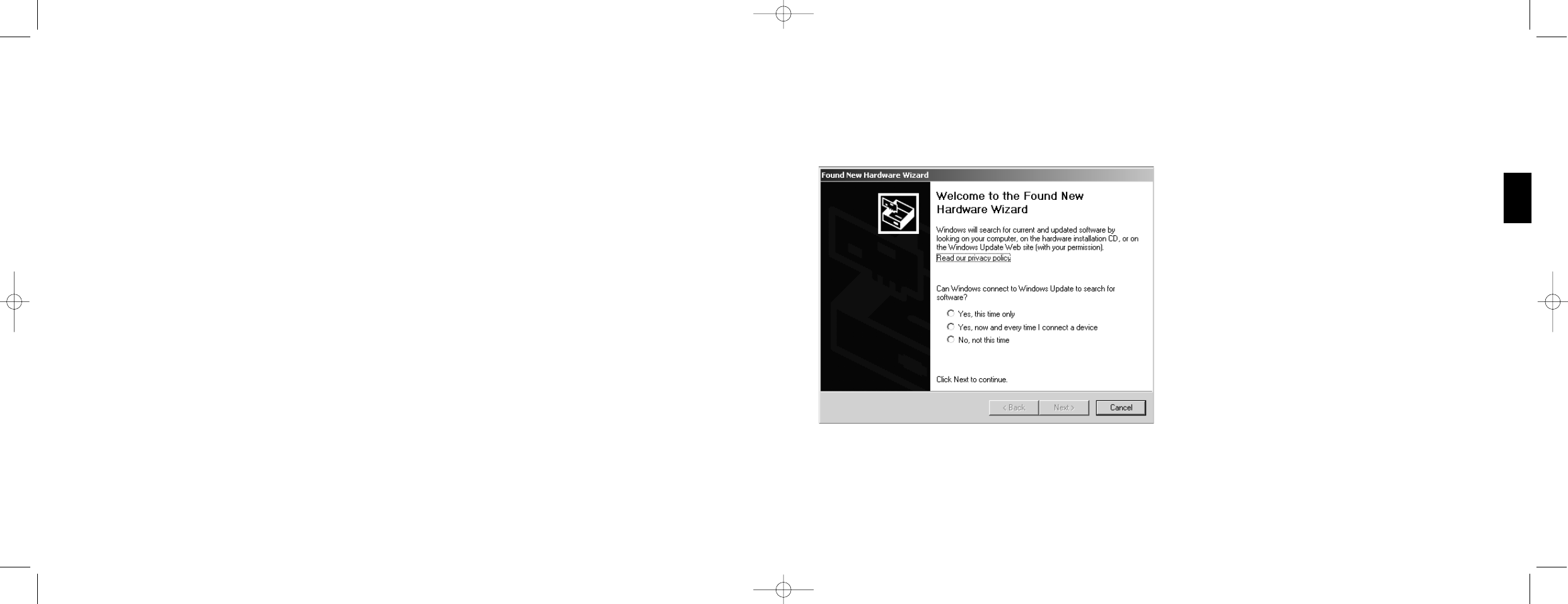
6 Nach dem Neustart erscheint das GerŠtetreiber-Installationsfenster. Klicken Sie auf Weiter und folgen Sie den
Bildschirmanweisungen.
7 Wenn die Installation abgeschlossen ist, stecken Sie bitte Ihren Controller am USB Anschluss Ihres Rechners an.
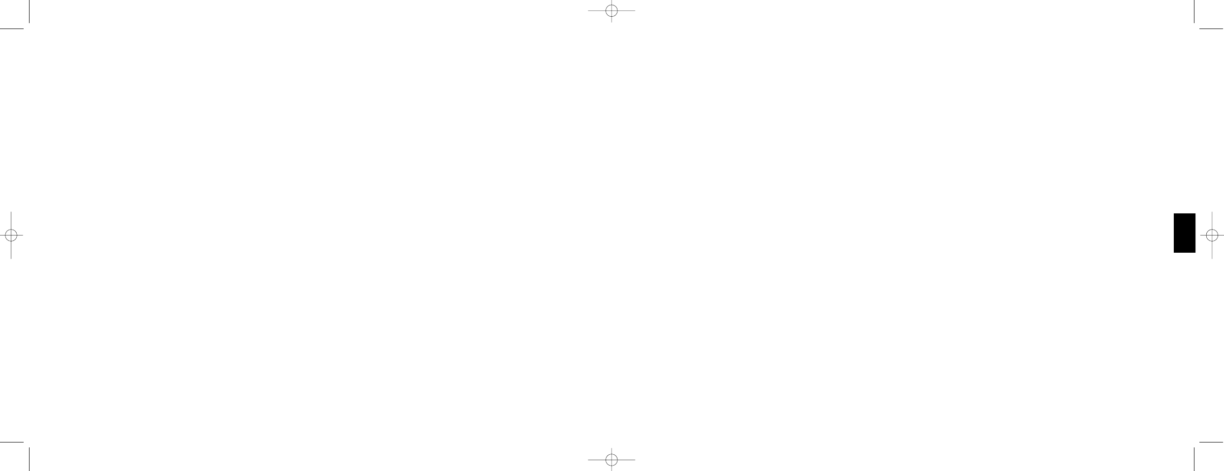
8 Erscheint das Fenster Controller Eigenschaften, klicken Sie bitte auf Weiter, um zum Test-Fenster zu gelangen.
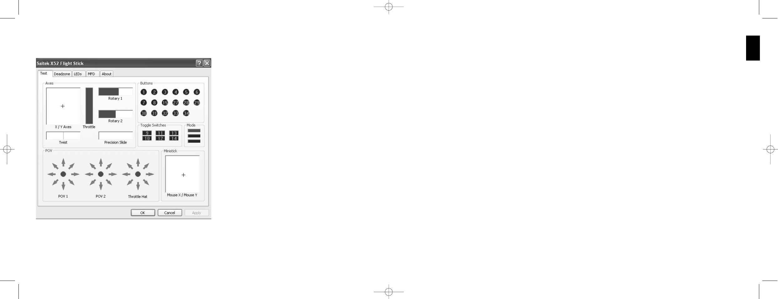
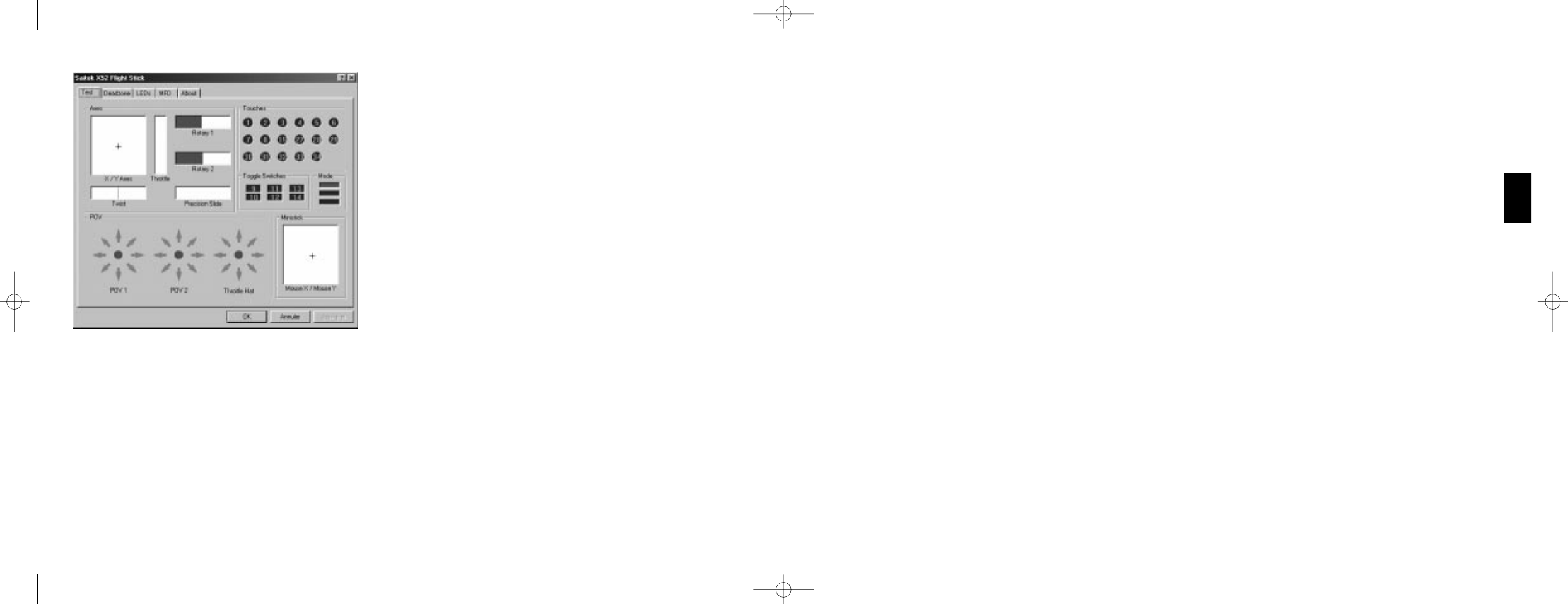
9 †berprŸfen Sie jetzt alle Tasten und Achsen auf ihre FunktionalitŠt. Ist der Test beendet, bestŠtigen Sie mit OK.
10 Im Fenster Programmiersoftware wŠhlen Sie die Option fŸr normale Nutzung und klicken Sie danach auf Weiter.
11 WŠhlen Sie bitte im Registrierungsfenster Registrierung meines Saitek Controllers Online. Klicken Sie dann
Weiter und folgen Sie den Bildschirmanweisungen oder wŠhlen Sie SpŠter Registrieren und klicken Sie Weiter.
12 Klicken Sie anschlie§end auf Fertigstellen, um die Installation zu beenden. Ihr Saitek Controller ist nun fertig
installiert und spielbereit.
B) Komplette Installation (Treiber und Programmier-Software)
Diese Installation wird den entsprechenden Treiber und die Saitek Smart Technology Programmierungssoftware fŸr
Saitek Controller installieren.
1 Folgen Sie Punkt 1 - 9 der Basisinstallation. WŠhlen Sie in dem Programmierungssoftware-Fenster dann
Fortgeschrittene Benutzer aus und klicken Sie Weiter.
2 Im Fenster Treiber klicken Sie Update und folgen Sie den Bildschirmanweisungen. An diesem Punkt werden Sie
aufgefordert, eine Windows¨ CD einzulegen. Folgen Sie NICHT dieser Aufforderung, sondern klicken Sie einfach
auf OK. Im nŠchsten Fenster tippen Sie C:\windows\system ein und klicken Sie OK. Folgen Sie den weiteren
Anweisungen am Bildschirm.
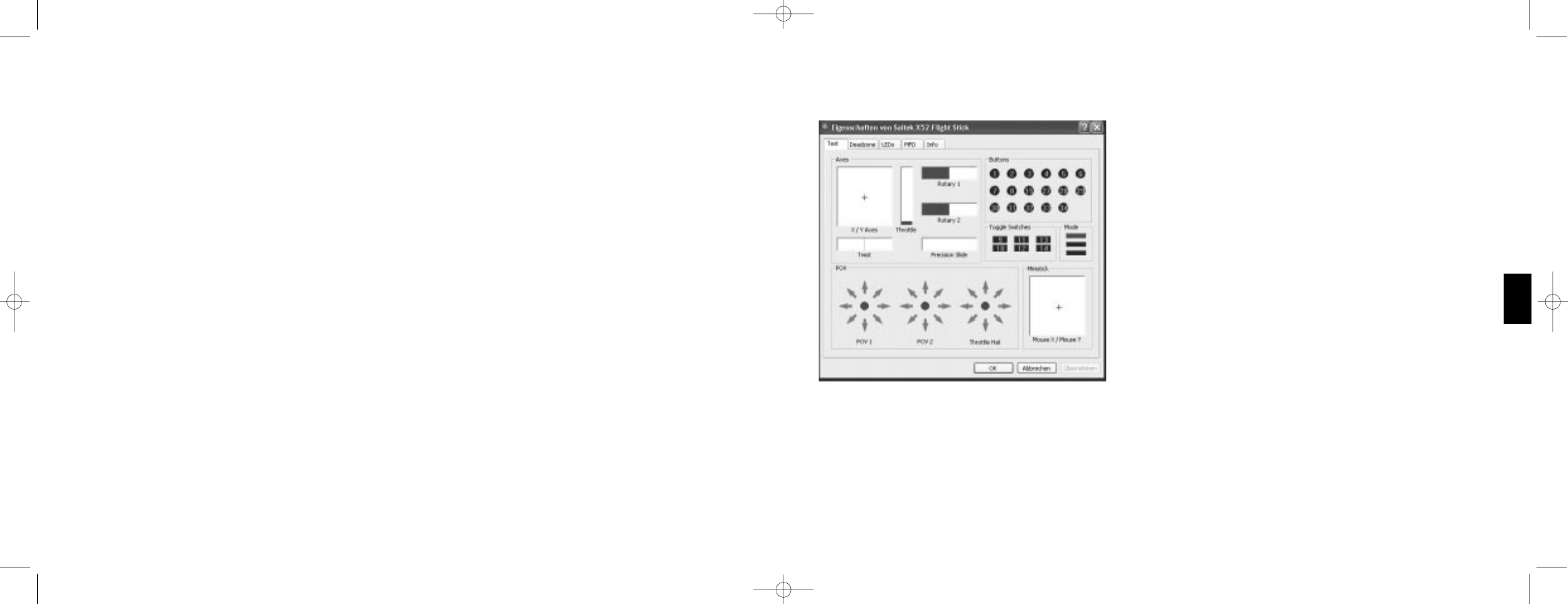
3 Wenn das Fenster Installation der Programmierungssoftware war erfolgreich erscheint, klicken Sie Weiter.
4 WŠhlen Sie bitte im Registrierungsfenster Registrierung meines Saitek Controllers Online. Klicken Sie dann
Weiter und folgen Sie den Bildschirmanweisungen oder wŠhlen Sie SpŠter Registrieren und klicken Sie Weiter.
5 Nach der Installation haben Sie die Option, den Profil-Editor zu starten, der Ihnen die Programmierungsumgebung
Ihres Controllers in einer dreidimensionalen Ansicht zeigt. Wenn Sie dies nicht wŸnschen, entfernen Sie das
HŠkchen in der Box und klicken Sie auf Installation fertigstellen. Ihr Saitek Controller ist nun zum Einsatz bereit.
69
DEUTSCH
B) Komplette Installation (Treiber und Programmier-Software)
1 Folgen Sie den Schritten 1-8 der Basisinstallation, und wŠhlen Sie dann die Option fŸr fortgeschrittene Anwender.
BestŠtigen Sie mit Weiter.
2 Unter Treiber, klicken Sie Update und folgen den Anweisungen.
3 Kommt die Meldung, dass die Installation erfolgreich war, klicken Sie Weiter.
4 Unter Registrierung kšnnen Sie auswŠhlen, ob Sie sich sofort oder spŠter registrieren wollen. Klicken Sie Weiter.
5 Nach Abschluss der Installation kšnnen Sie sofort den Profileditor starten - heisst die Programmierung beginnen.
Entscheiden Sie sich dafŸr, nicht sofort zu programmieren, klicken Sie Fertigstellen, um dies zu Ÿbergehen. Ihr
Saitek Controller ist spielbereit.
INSTALLATION UNTER WINDOWS¨ 98 UND ME
A) Basisinstallation (nur Treiber)
Mit dieser Installation richten Sie NUR Treiber fŸr Ihren Controller ein. Die volle Installation wird separat beschrieben und
richtet Software + Treiber ein
1 Im Begr٤ungsbildschirm klicken Sie bitte auf Software installieren, um fortzufahren. Wenn die CD nicht
automatisch startet, wŠhlen Sie bitte Start in der Windows MenŸleiste, dann AusfŸhren und hier geben Sie
D:\Setup.exe (ohne AnfŸhrungszeichen) ein und klicken Sie OK. Falls D:\ nicht der Laufwerksbuchstabe Ihres CD
Laufwerks ist Šndern Sie diesen entsprechend.
2 Wenn das Start-Fenster erscheint, klicken Sie bitte auf Software installieren, um fortzufahren.
3 Klicken Sie im ersten Fenster auf Weiter, um fortzufahren.
4 Nachdem Sie die Nutzungsbedingungen des Herstellers gelesen haben, klicken Sie bitte auf Weiter, um
fortzufahren.
Hinweis: Sie mŸssen mindestens Microsoft DirectX 8.1 (oder eine neuere Version) auf Ihrem Rechner installiert
haben, damit Ihr Saitek Controller funktionsbereit ist. Die Installationsroutine ŸberprŸft automatisch, ob diese
Software noch installiert werden muss, und wird diese, falls notwendig, direkt von der Saitek Produkt CD laden.
Wenn Sie dazu aufgefordert werden Microsoft DirectX 8.1 zu installieren, klicken Sie bitte auf Installieren, folgen
Sie anschlie§end den Bildschirmanweisungen und starten Sie danach Ihren PC neu. Bitte versichern Sie sich, dass
sich die Saitek CD noch in Ihrem CD-ROM Laufwerk befindet, wenn Sie den PC neustarten. Sobald Microsoft¨
68
X52 manual(ok)(24/11/04) 2004.12.22 9:05 PM Page 68
1 Klicken Sie auf die Test-Leiste.
Die ŸberprŸfbaren Eigenschaften werden folgenderma§en angezeigt:
2 Testen Sie jede Funktion nach Bedarf. Der Testablauf hŠngt von der ausgewŠhlten Funktion ab. Sie mŸssen dabei
z. B. die entsprechende Taste drŸcken oder die entsprechende Drehkontrolle drehen.
Die ŸberprŸfbaren Funktionen werden in den folgenden Abschnitten erklŠrt.
71
DEUTSCH
CONTROLLER-EINSTELLUNGEN VORNEHMEN
Ihr Saitek X52 Flugsteuerungssystem (FCS) wird betriebsfertig geliefert. Damit Sie es jedoch entsprechend Ihren
eigenen WŸnschen einstellen und verwenden kšnnen, haben Sie die Mšglichkeit, verschiedene Einstellungen auf Ihren
Joystick- und Schubreglereinheiten vorzunehmen. Sie kšnnen zum Beispiel die Helligkeit der LED-Tasten anpassen,
ŸberprŸfen, ob Ihr Joystick korrekt funktioniert oder das auf der Multi-Funktionsanzeige (MFD) dargestellte Datumsformat
einstellen.
Sie kšnnen die Anpassung der Controller-Einstellungen in der Einstellungsansicht des Saitek X52-Flight Stick
vornehmen. Sie kšnnen das Fenster auf zweierlei Arten šffnen. Entweder:
¥ Das Game Controllers-Symbol in der Systemsteuerung doppelklicken und dann im angezeigten Game Controllers-
Fenster auf Eigenschaften klicken.
oder
¥ Falls die SST-Programming-Software installiert ist, das Saitek X52-Flight Stick-Profilsymbol in der Taskleiste rechts
anklicken und die Option Systemsteuerung aus der Popup-Liste auswŠhlen.
Das Eigenschaftenfenster des Saitek X52-Flight Sticks besteht aus fŸnf verschiedenen Leisten. Sie kšnnen in jeder
Leiste verschiedene Controller-Einstellungen einsehen und abŠndern. Die vornehmbaren Einstellungen werden in den
folgenden Abschnitten beschrieben.
Controller testen
†ber die Test-Leiste des Eigenschaftenfensters des Saitek X52-Flight Sticks kšnnen Sie sicherstellen, dass die
verschiedenen Funktionen Ihres Controllers funktionieren.
Zur †berprŸfung Ihrer Controller befolgen Sie die Schritte unten:
70
X52 manual(ok)(24/11/04) 2004.12.22 9:05 PM Page 70
Funktionen unter Verwendung der SST-Programming-Software zuweisen. Einzelheiten dazu finden Sie im SST-
Programming-Software-Handbuch.
Die nummerierten Zellen in der Umschalter-Leiste leuchten auf, wenn Sie die Umschalter auf Ihrem Flight Stick drŸcken.
Die drei roten Zellen auf der Modus-Leiste zeigen den ausgewŠhlten Modus an. Die obere Zelle zeigt Modus 1, die
mittlere Zelle Modus 2 und die untere Zelle Modus 3 an. Stellen Sie sicher, dass Ihr Modusauswahlschalter korrekt
funktioniert, indem Sie den Schalter zum Umschalten zwischen den Betriebsarten verwenden. Die entsprechende Zelle
in der Modus-Leiste leuchtet auf.
POVs testen (Point of View / Rundumblickschalter)
Wenn Sie die POV-Steuerungen auf Ihrem Flight Stick in verschiedene Richtungen bewegen, sollten die entsprechenden
Richtungspfeile in der POV-Leiste aufleuchten. POV 1 wird zur Innenansicht des Cockpits verwendet. POV 2 kann dazu
verwendet werden, vier bzw. acht verschiedene Funktionen Ihrer Wahl auszulšsen. Einzelheiten dazu finden Sie im SST-
Programming-Software-Handbuch.
Sie kšnnen auch sicherstellen, dass durch Bewegungen der Rundumblicksteuerung die entsprechenden Richtungspfeile
in der POV-Leiste aufleuchten. Bei POV 2 kann die Rundumblicksteuerung konfiguriert werden, sodass vier oder acht
verschiedene Funktionen Ihrer Wahl ausgelšst werden.
Ministick testen
Der Ministick auf der Schubreglereinheit wird fŸr Funktionen verwendet, die Sie Ÿblicherweise mit der Maus durchfŸhren
wŸrden. Durch die Bewegung des Ministicks erscheint das + Symbol in der Maus X/Maus Y-Zelle.
Einstellen von toten Zonen
Sie kšnnen fŸr jeden Bereich und jede Achse, in denen sich Ihre Controller-Funktionen bewegen, tote Zonen erstellen.
Dadurch werden Stšrungen reduziert, die durch unabsichtliche Bewegungen des Flight Sticks und anderer
Steuerelemente entstehen. Angenommen, Sie mšchten z. B. Ihren Stick nur auf der X-Achse bewegen, aber finden es
schwierig, ihn dabei nicht gleichzeitig auch auf der Y-Achse zu bewegen. Sie kšnnen eine tote Zone auf der Y-Achse
erstellen, damit der Treiber diese kleinen Bewegungen nicht wahrnimmt.
Was ist eine tote Zone?
Eine tote Zone ist ein Teilbereich, in dem sich eine Achse bewegt, ohne von den Treibern erkannt zu werden. Diese
Bewegung hat daher keine Auswirkung auf das aktive Spiel. Die tote Zone kann um den Mittelpunkt des Bereichs oder
an beiden Enden eingestellt werden.
73
DEUTSCH
Achsen testen
Sie kšnnen die folgenden Achsen und Steuerelemente testen:
Funktion ErlŠuterung
X-/Y-Achsen Bewegen Sie den Flight Stick nach hinten und nach vorne bzw. von links
nach rechts. Das + Symbol bewegt sich in der X-/Y-Achsen-Zelle um
anzuzeigen, dass die Treiber die Bewegung des Sticks korrekt registrieren.
Drehung Die vertikale graue Linie stellt den Mittelpunkt des Flight Sticks dar. Drehen
Sie den Flight Stick im oder gegen den Uhrzeigersinn. Das ist das Ruder,
das Ihnen RichtungsŠnderungen au§erhalb der X- und Y-Achsen ermšglicht.
Wenn die Treiber die Bewegung korrekt erkennen, erscheint ein rotes Band
an beiden Seiten der Mittelpunktlinie.
Schubregler Bewegen Sie den Schubregler zur Erhšhung oder Verringerung der
Beschleunigung nach oben oder unten. Ein rotes Band zeigt die aktuelle
Beschleunigungsstufe an, von 0 % (kein Rot) bis zur maximalen
Beschleunigung bei 100 % (die Zelle ist rot ausgefŸllt).
Drehregler 1 und 2 Drehen Sie die Drehregler der Schubregler-Einheit. Diese werden
Ÿber die SST-Programming-Software oder wŠhrend jedes Spiels
benutzerdefiniert. Sie reichen von 0 % (kein Rot) bis 100 % (die Zelle ist rot
ausgefŸllt). Sie kšnnen sie z. B. zur Einstellung des Treibstoffgemisches
oder zur RadarverstŠrkung verwenden.
PrŠzisionsschieber Bewegen Sie den PrŠzisionsschieber auf der Schubregler-Einheit. Die
Funktion wird Ÿber die SST-Programming-Software oder wŠhrend jedes
Spiels benutzerdefiniert und reicht von 0 %(kein Rot) bis 100 % (die Zelle ist ~
rot ausgefŸllt). Sie kšnnen ihn z. B. zur Einstellung der Propellersteigung
oder des Treibstoffgemisches verwenden.
Testschalter, Umschalter und Modusauswahlschalter
Sie kšnnen ŸberprŸfen, ob das DrŸcken der Tasten von den Treibern erkannt wird. DrŸcken Sie nacheinander jede zu
ŸberprŸfende Taste auf Ihrem Flight Stick oder auf der Schubreglereinheit. Die entsprechende nummerierte Scheibe
leuchtet in der Schalter-Leiste auf der Test-Leiste auf.
Hinweis: Die Funktion jeder Taste hŠngt vom aktuellen Spiel ab. Sie kšnnen nach Wunsch einzelnen Tasten bestimmte
72
X52 manual(ok)(24/11/04) 2004.12.22 9:05 PM Page 72
¥ Der mittlere Bereich der MFD wird dazu verwendet, die Bezeichnungen der Tasten auf Ihrem Flight Stick und
Schubregler anzusehen bzw. um das aktuelle Profil anzusehen und zu verŠndern. Siehe Arbeiten mit
Profilinformation unten.
¥ Die Zeit- und Datumsanzeige befindet sich unten auf der MFD. Die aktuelle Zeit wird in bis zu drei Zeitzonen
angezeigt. Ferner enthŠlt sie die Stoppuhr. Siehe Zeit und Datum ansehen und Stoppuhr verwenden unten.
Das Layout der MFD wird in der folgenden Abbildung dargestellt:
Die drei Tasten unterhalb der MFD dienen zur Einstellung der
Zeitanzeige und Bedienung der Stoppuhr.
Arbeiten mit Betriebsmodi
Das Saitek X52 bietet Ihnen umfangreiche
Konfigurationsmšglichkeiten, damit Ihr Controller entsprechend Ihren
Vorlieben funktioniert. Dies ist durch die Erstellung von Profilen
unter der Verwendung der SST-Programming-Software mšglich.
(Weitere Informationen finden Sie in der Anleitung der SST-
Programming-Software). In jedem Profil kšnnen Sie bis zu sechs
verschiedene Betriebsmodi einstellen, die die auf Tastendruck auf
dem Flight Stick und Schubregler auszufŸhrenden AblŠufe festlegen.
Sie kšnnen Ihre MFD zum Ansehen des aktiven Betriebsmodus
verwenden.
Betriebsmodus Šndern
Sie kšnnen den Betriebsmodus durch Drehen der Modusauswahl
auf Ihrem Flight Stick Šndern. Dabei Šndert sich die angezeigte
BETRIEBSMODUS-Nummer entsprechend auf der MFD.
ZusŠtzliche Betriebsmodi verwenden
Drei Betriebsmodi sind in der Grundeinstellung verfŸgbar. Mithilfe
des Pinkie-Switch auf dem Flight Stick (fŸr den kleinen Finger)
kšnnen Sie diese auf sechs Modi erweitern. Dazu weisen Sie dem
Pinkie-Switch unter der Verwendung der SST-Programming-
81
DEUTSCH
Verwenden der MFD
Die MFD oder Multifunktionsanzeige ist ein wesentlicher Bestandteil Ihrer Schubreglereinheit. Sie zeigt eine Vielzahl von
Informationen an, wie z. B. Tastennamen, aktuelles Profil und Datum. Au§erdem bietet sie eine Stoppuhrfunktion.
Sie kšnnen einige der Einstellungen anpassen, die die Funktionsweise der MFD festlegen. Angenommen, Sie mšchten
z. B. die Helligkeit der Anzeige erhšhen oder das angezeigte Datumsformat Šndern. Diese Einstellung kšnnen sie in der
MFD-Leiste des Fensters Eigenschaften des Saitek X52-Flight Sticks vornehmen. Weitere Informationen finden Sie in
MFD-Einstellungen vornehmen im Abschnitt Controllereinstellungen vornehmen.
Funktionen der MFD
Die MFD ist in drei Teile gegliedert:
¥ Der Betriebsmodus-Teil befindet sich oben auf der MFD und zeigt den ausgewŠhlten Betriebsmodus an. Siehe
Arbeiten mit Betriebsmodi unten.
80
X52 manual(ok)(24/11/04) 2004.12.22 9:05 PM Page 80
40


Need help? Post your question in this forum.

Forumrules


Report abuse

Libble takes abuse of its services very seriously. We're committed to dealing with such abuse according to the laws in your country of residence. When you submit a report, we'll investigate it and take the appropriate action. We'll get back to you only if we require additional details or have more information to share.

Product:

For example, Anti-Semitic content, racist content, or material that could result in a violent physical act.

For example, a credit card number, a personal identification number, or an unlisted home address. Note that email addresses and full names are not considered private information.

Forumrules

To achieve meaningful questions, we apply the following rules:

Register

Register getting emails for Saitek SAITEK X52 FLIGHT CONTROL SYSTEM at:


You will receive an email to register for one or both of the options.


Get your user manual by e-mail

Enter your email address to receive the manual of Saitek SAITEK X52 FLIGHT CONTROL SYSTEM in the language / languages: English, German, French, Italian, Spanish as an attachment in your email.

The manual is 1,31 mb in size.


You will receive the manual in your email within minutes. If you have not received an email, then probably have entered the wrong email address or your mailbox is too full. In addition, it may be that your ISP may have a maximum size for emails to receive.

The manual is sent by email. Check your email

If you have not received an email with the manual within fifteen minutes, it may be that you have a entered a wrong email address or that your ISP has set a maximum size to receive email that is smaller than the size of the manual.

The email address you have provided is not correct.

Please check the email address and correct it.

Your question is posted on this page

Would you like to receive an email when new answers and questions are posted? Please enter your email address.


Info