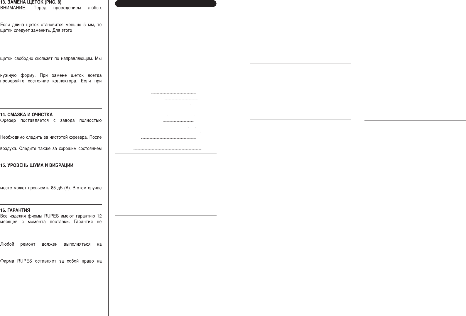
Per fissare l'asta di profondità sulla posizione
desiderata, rilasciare la manopola di regolazione.
Poi, pergarantire il perfetto fissaggio dell'asta,
bloccare con la manopola di fissaggio N (Fig. 4).
REGOLAZIONE DI PRECISIONE. Se si deside-
ra regolare o correggere con precisione la pro-
fondità precedentemente impostata, agire sulla
manopola di regolazione fine O(Fig. 4). Un giro
completo della manopola corrisponde a uno spo-
stamento dell'asta di 1 mm, con una corsa mas-
sima di 5 mm. Ogni segmento dell'indicatore gra-
duato di regolazione fine P (Fig. 4) corrisponde a
un avanzamento di 0,1 mm.
REALIZZAZIONE DI TAGLI PROFONDI. Per
realizzare in sicurezza un taglio molto profondo,
è consigliabile non eseguirlo in una sola passata
ma procedere per tagli successivi, utilizzando i
sei gradini da 3 mm della torretta girevole di pro-
fondità Q (Fig. 4).
Abbassare la macchina fino ad allineare la fresa
alla superficie di appoggio della fresatrice. Con la
manopola di bloccaggio J (Fig. 3), fissare la mac-
china in questa posizione. Allentare la manopola
di fissaggio N (Fig. 4), premere la manopola di
regolazione L (Fig. 4) e girarla fino a far arrivare
l'asta di profondità in fondo al gradino inferiore
della torretta girevole, utilizzando se necessario
la regolazione fine. In questa posizione, girare
l'indicatore di profondità M (Fig. 4) fino a far coin-
cidere il segno di riferimento con la posizione
zero. Questa sarà la posizione di inizio e cioè
quella in cui la fresa entrerà a contatto con il
pezzo da lavorare. Fissare l'asta con la manopo-
la N (Fig. 4), sbloccare la manopola di bloccaggio
e lasciare la macchina in posizione di riposo.
Allentare la manopola di fissaggio N, premere e
girare la manopola di regolazione L spostando
l'asta di regolazione K (Fig. 4) verso l'alto fino a
raggiungere la profondità di taglio desiderata e,
mediante la manopola N, girare di nuovo la tor-
retta Q (Fig. 4) fino a che il gradino più alto si tro-
verà sotto l'asta K (Fig. 4). Realizzare la prima
passata di taglio sul pezzo in lavorazione. Girare
la torretta Q fino al successivo gradino, effettua-
re un'altra passata e così via, fino a raggiungere
la profondità finale desiderata nel momento in cui
si arriva al gradino inferiore.
9. COME BLOCCARE LA
PROFONDITÀ DI FRESATURA
Per l'esecuzione di lavori ripetitivi o per i quali la
profondità di fresatura è sempre la stessa, e nei
casi in cui è meglio evitare che la testa possa
venire sbloccata da una manovra involontaria
della leva di blocco J (Fig. 3), si può fissare la
testa alla profondità desiderata intercalando due
dadi M8 R (Fig. 3) sull'albero filettato, uno sopra
e l'altro sotto il corpo della testa, che permette-
ranno di bloccarla in qualunque punto della
corsa.
ATTENZIONE! Quando si lavora con la profondi-
tà di fresatura bloccata, l'utensile resta per-
manentemente fuori dalla superficie della base e
quindi occorre:
-Aspettare che la macchina si fermi completa-
mente prima di lasciarla, sulla base, su una
superficie piana in modo da liberare l'utensile.
- Togliere i dadi R (Fig. 3), per tornare alle condi-
zioni normali di blocco con la leva J (Fig. 3) al ter-
mine del lavoro.
10. UTILIZZAZIONE DELLE
GUIDE PARALLELE
La guida parallela si usa per la profilatura di bordi
e per il taglio di scanalature di forme diverse, a
seconda delle diverse forme di profili. Per la rifi-
nitura dei bordi e per una maggior vita delle frese
sono particolarmente utili le frese di metallo duro.
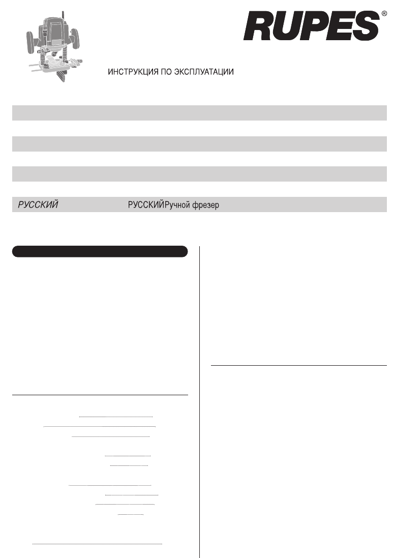
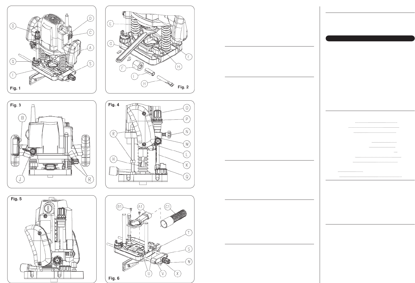
La guida parallela S (Fig. 6) va collocata nelle
aperture della base T (Fig. 6) e fissata mediante
i due pomelli U (Fig. 6).
REGOLAZIONE NORMALE DELLA SQUADRA
– Allentare le manopole U (Fig. 6) della base,
spostare la squadra fino alla misura desiderata e
stringere i pomelli in questa posizione.
REGOLAZIONE DI PRECISIONE - Una volta
sistemata e fissata approssimativamente la
squadra, è possibile effettuare una regolazione di
precisione. Per farlo, allentare la manopola di fis-
saggio della squadra V (Fig. 6), ruotare la mano-
pola di regolazione W (Fig. 6) fino alla misura
desiderata e fissare nuovamente in questa posi-
zione la manopola di fissaggio V (Fig. 6) della
squadra. Un giro completo della manopola di
regolazione corrisponde a uno spostamento
della squadra di 1 mm, con una corsa massima
di 10 mm. L'indicatore graduato di regolazione
fine X (Fig. 6) può muoversi indipendentemente
dalla manopola e ciò permette di posizionare il
segno di riferimentosullozero in qualunque posi-
zione. Dopo aver regolato l'indicatore X (Fig. 6),
quando si gira nuovamente la manopola W (Fig.
6), questa girerà con lui e, sapendo che ogni divi-
sione corrisponde a un avanzamento di 0,1 mm,
ciò indicherà lo spostamento della squadra.
11. UTILIZZAZIONE DEL
PALPATORE DI SAGOMA
4