INTRODUCTION . . . . . . . . . . . . . . . . . . . . . . . . . . . . .3
Additional Technical Help, Support and Service . . . . .3
Application, Export and Modification . . . . . . . . . . . . .4
Meaning of Special Markings . . . . . . . . . . . . . . . . . . .5
Safety Precautions (do not operate without reading) . .5
Introduction to the 9C . . . . . . . . . . . . . . . . . . . . . . . . .7
Contents and Technical Specifications . . . . . . . . . . . .9
Accessories . . . . . . . . . . . . . . . . . . . . . . . . . . . . . . .10
Transmitter Controls &
Switch Identification/Assignments . . . . . . . . . . . . . .11
Charging the Ni-Cd Batteries . . . . . . . . . . . . . . . . . .14
Stick Adjustments . . . . . . . . . . . . . . . . . . . . . . . . . . .15
Adjusting display contrast . . . . . . . . . . . . . . . . . . . .15
Changing mode . . . . . . . . . . . . . . . . . . . . . . . . . . . .15
Radio Installation & Range Checking . . . . . . . . . . . .16
Aircraft Frequencies . . . . . . . . . . . . . . . . . . . . . . . . .17
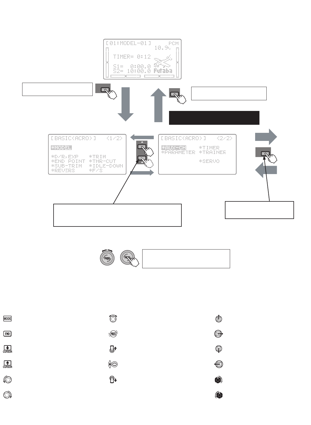
Transmitter Displays and Buttons . . . . . . . . . . . . . . .18
Warning and Error Displays . . . . . . . . . . . . . . . . . . .19
AIRPLANE (ACRO) FUNCTIONS . . . . . . . . . . . . . . . .20
Map of Functions . . . . . . . . . . . . . . . . . . . . . . . . . . .21
Quick Guide to Setting up a 4-channel Airplane . . . .22
ACRO BASIC MENU FUNCTIONS . . . . . . . . . . . . . . . .25
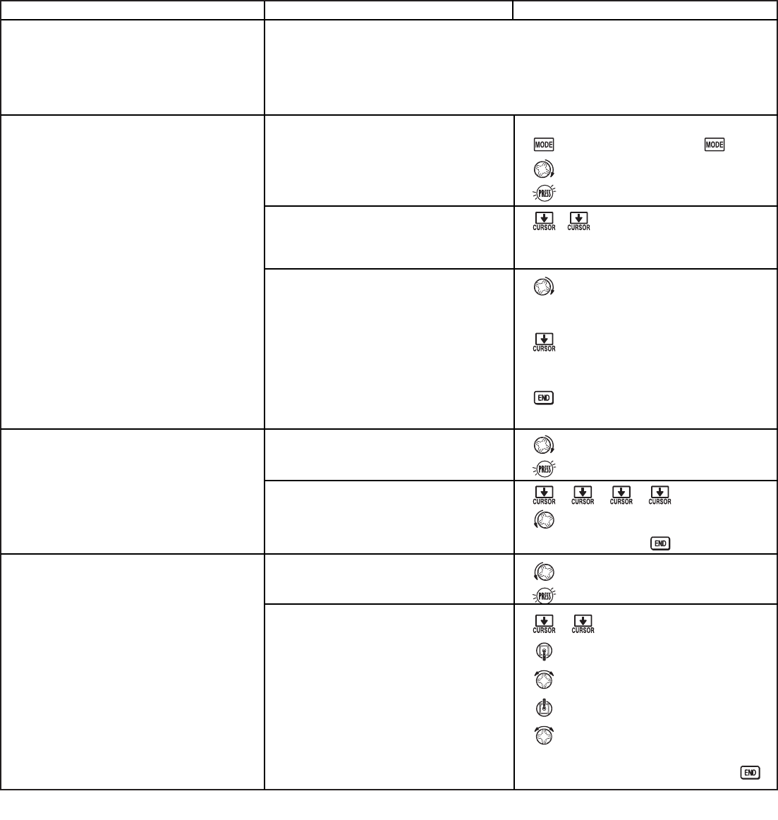
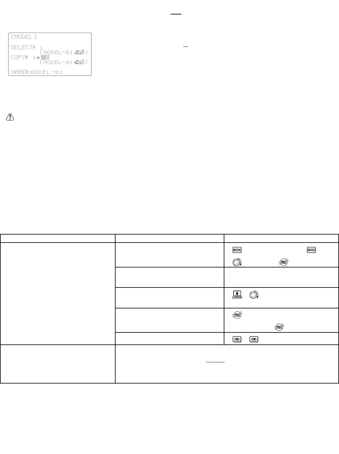
MODEL Submenu: MODEL SELECT, COPY and NAME . .25
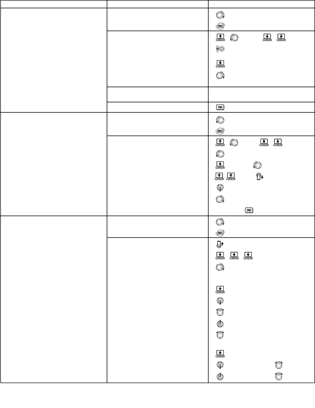
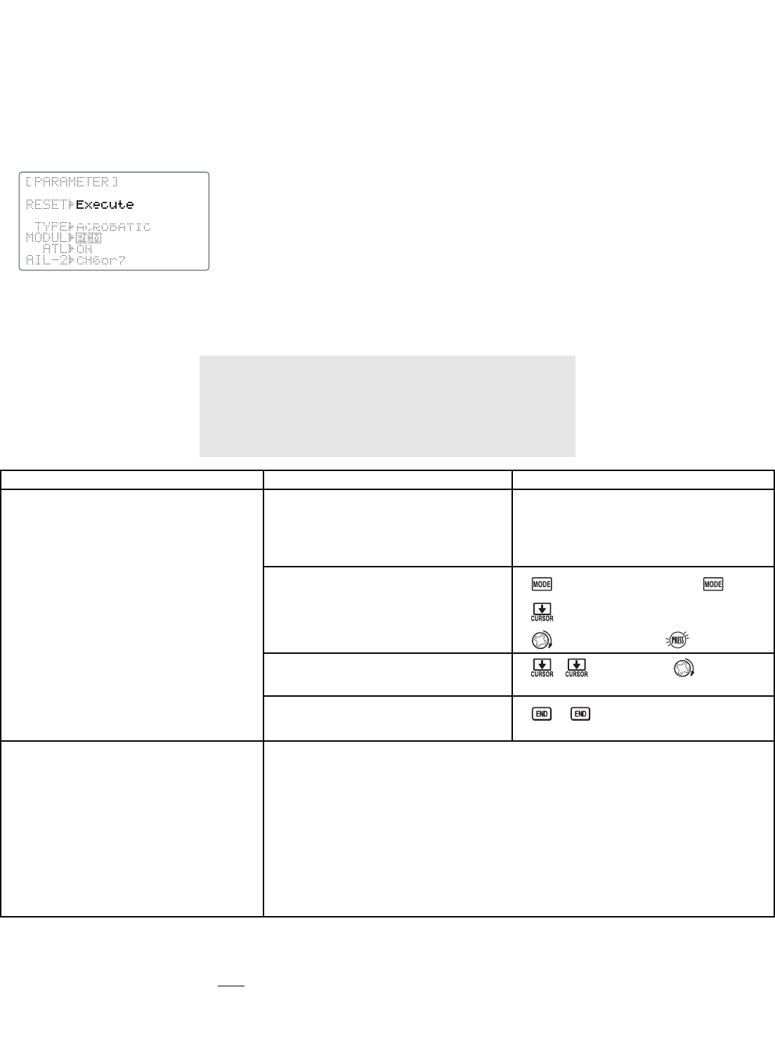
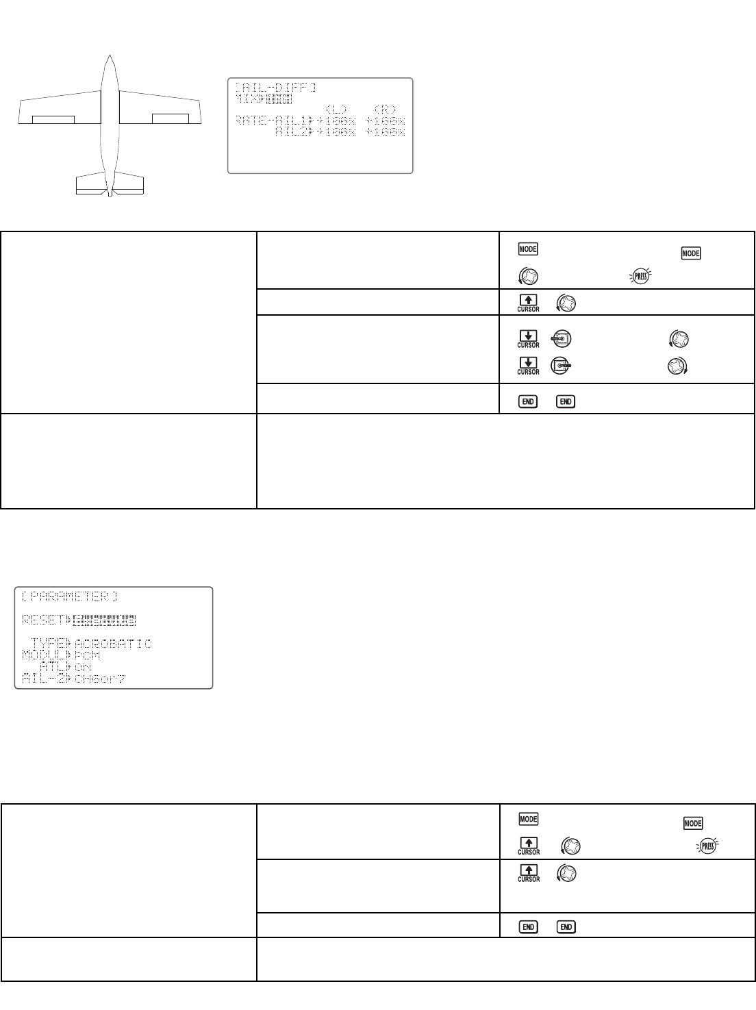
PARAMETER Submenu: TYPE, MODUL, ATL, AIL2,
& RESET . . . . . . . . . . . . . . . . . . . . . . . . . . . . . . . . . .28
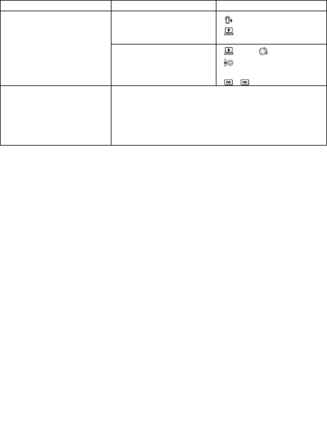
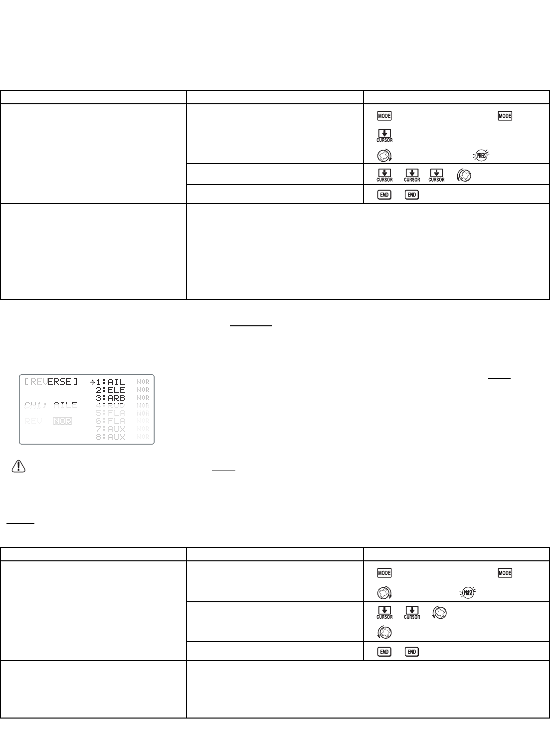
Servo REVERSE . . . . . . . . . . . . . . . . . . . . . . . . . . . . .31
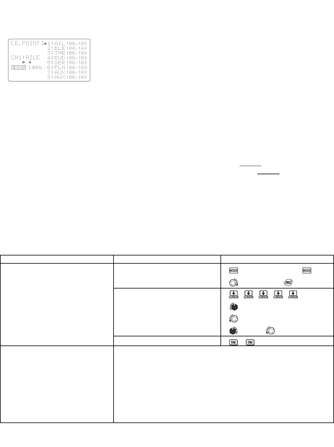
END POINT . . . . . . . . . . . . . . . . . . . . . . . . . . . . . . . .32
Idle Management: IDLE DOWN and THR-CUT . . . . . . . .33
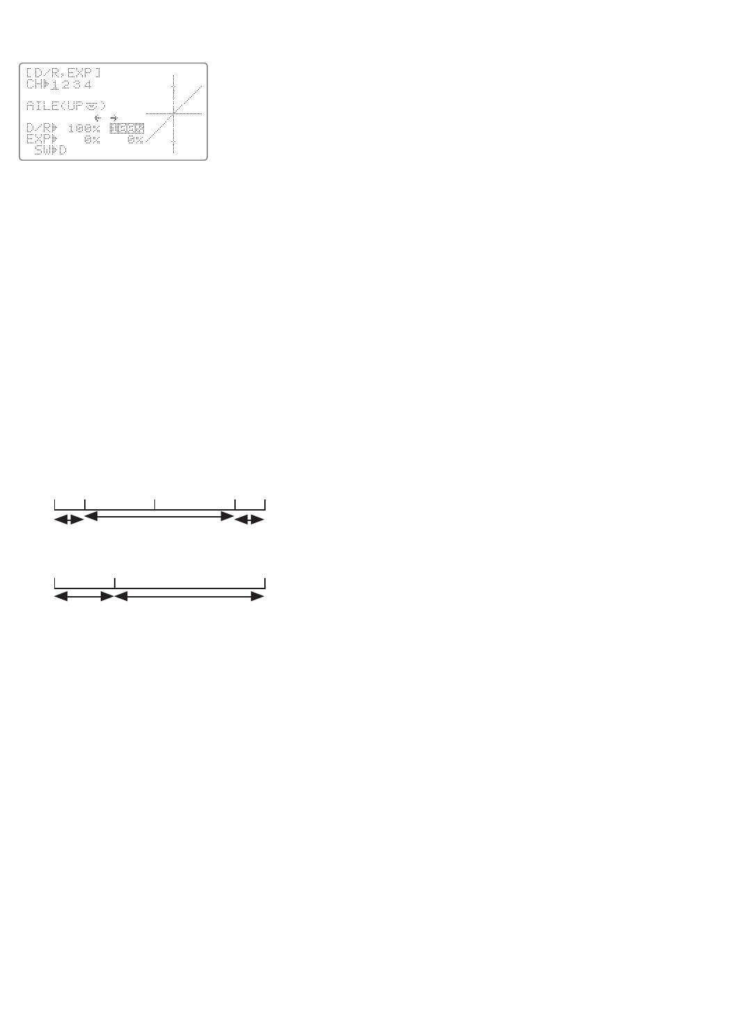
Dual/Triple Rates and Exponential (D/R,EXP) . . . . . .35
TIMER Submenu . . . . . . . . . . . . . . . . . . . . . . . . . . . .38
Auxiliary Channel assignments and
CH9 reverse (AUX-CH) . . . . . . . . . . . . . . . . . . . . . . . .39
TRAINER . . . . . . . . . . . . . . . . . . . . . . . . . . . . . . . . . .40
TRIM and SUB-TRIM . . . . . . . . . . . . . . . . . . . . . . . . . .41
SERVO Display . . . . . . . . . . . . . . . . . . . . . . . . . . . . .42
Fail Safe and Battery FailSafe (F/S) . . . . . . . . . . . . .43
ACRO ADVANCE MENU FUNCTIONS . . . . . . . . . . . . . .44
Wing types . . . . . . . . . . . . . . . . . . . . . . . . . . . . . . . .44
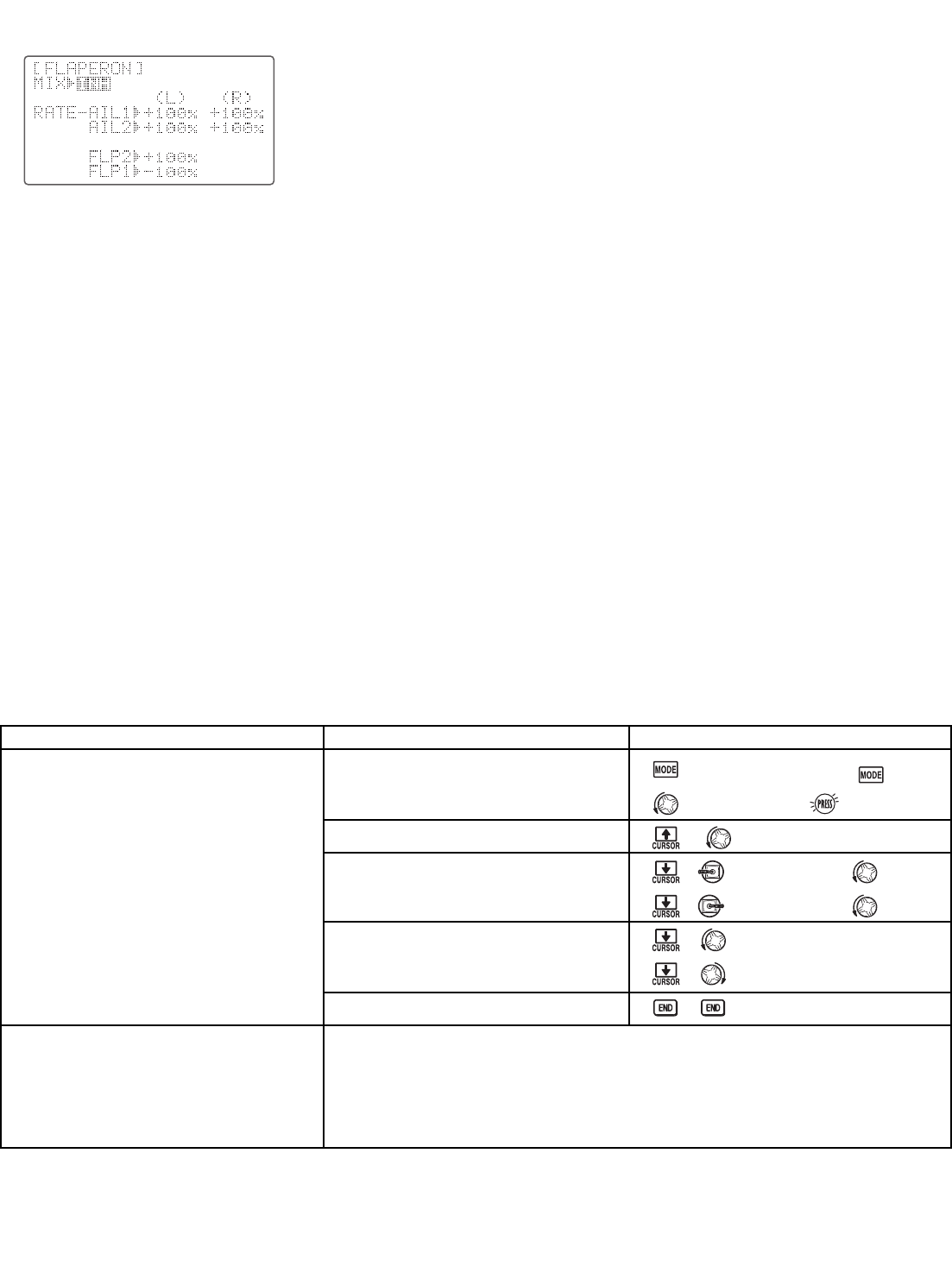
FLAPERON . . . . . . . . . . . . . . . . . . . . . . . . . . . . . .45
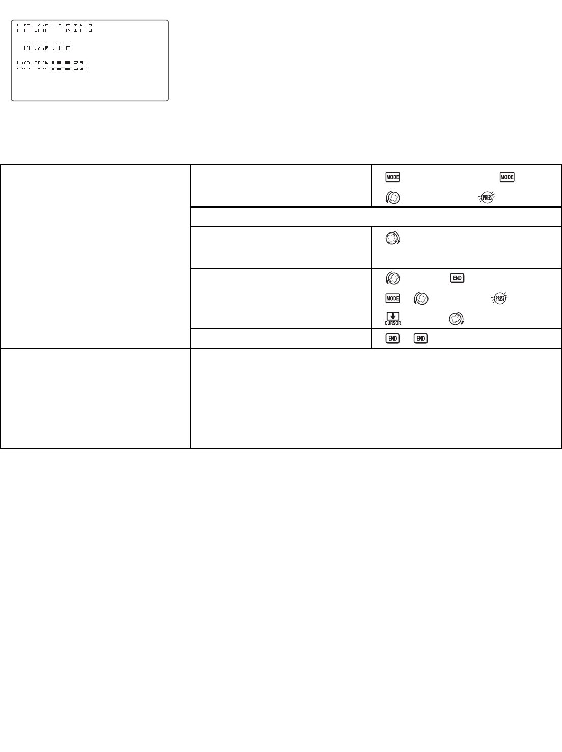
FLAP TRIM . . . . . . . . . . . . . . . . . . . . . . . . . . . . . .46
Aileron Differential (AIL-DIFF) . . . . . . . . . . . . . . .47
Using a 5-channel receiver: AIL-2 . . . . . . . . . . . . .47
ELEVON (see tail types) . . . . . . . . . . . . . . . . . . . . .48
Tail types . . . . . . . . . . . . . . . . . . . . . . . . . . . . . . . . .48
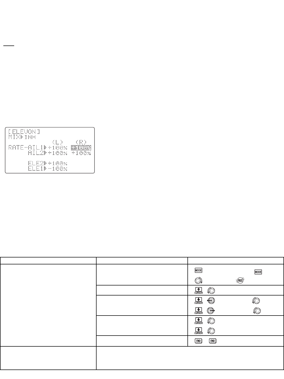
ELEVON . . . . . . . . . . . . . . . . . . . . . . . . . . . . . . . .48
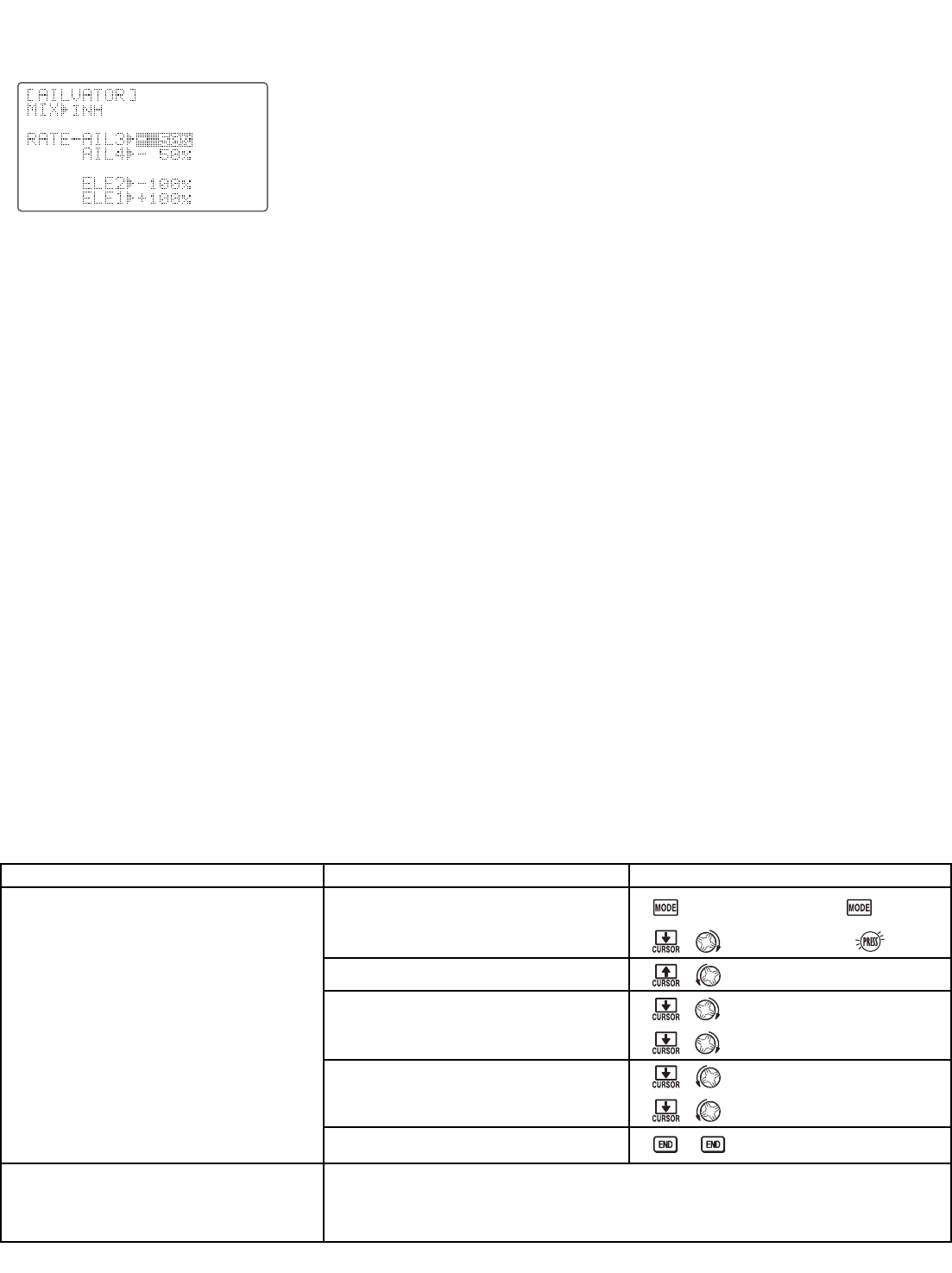
Twin Elevator Servos (AILEVATOR) . . . . . . . . . . . .49
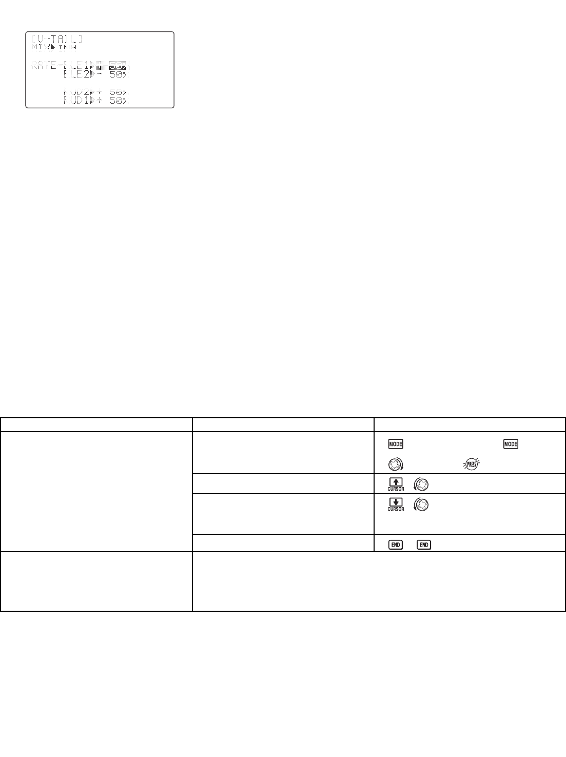
V-TAIL . . . . . . . . . . . . . . . . . . . . . . . . . . . . . . . . . .50
SNAP ROLL . . . . . . . . . . . . . . . . . . . . . . . . . . . . . . . .51
Mixes: definitions and types . . . . . . . . . . . . . . . . . . .53
ELEV-FLAP . . . . . . . . . . . . . . . . . . . . . . . . . . . . . .54
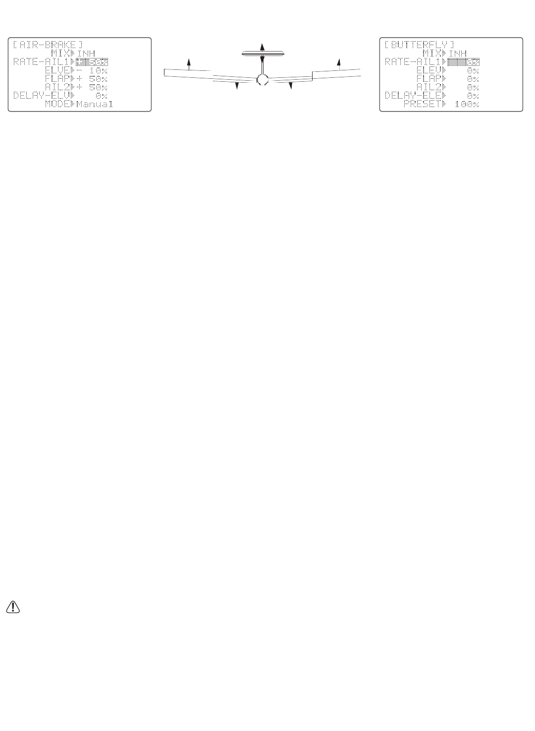
AIRBRAKE/BUTTERFLY (crow) . . . . . . . . . . . . . . . .55
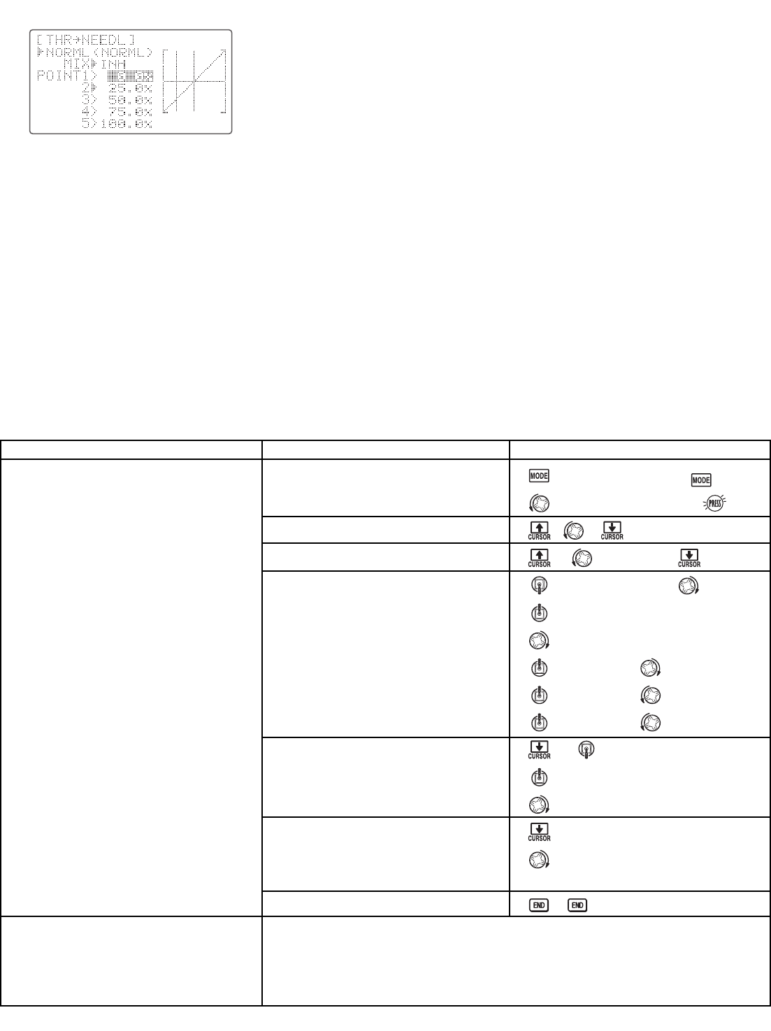
THROTTLE-NEEDLE . . . . . . . . . . . . . . . . . . . . . . . . .56
THROTTLE DELAY . . . . . . . . . . . . . . . . . . . . . . . . . .57
Linear, Prog. mixes 1-5 . . . . . . . . . . . . . . . . . . . . .59
Curve, Prog. mixes 6-7 . . . . . . . . . . . . . . . . . . . . .62
Other Equipment . . . . . . . . . . . . . . . . . . . . . . . . . . . . .64
GLIDER (GLID1FLP/2FLP) FUNCTIONS . . . . . . . . . . .65
Table of contents . . . . . . . . . . . . . . . . . . . . . . . . . . .65
Getting Started with a Basic 4-CH Glider . . . . . . . . .66
GLIDER-SPECIFIC BASIC MENU FUNCTIONS . .68
Model type (PARAMETERS submenu) . . . . . . . . . .68
GLIDER-SPECIFIC ADVANCE MENU FUNCTIONS 69
BUTTERFLY . . . . . . . . . . . . . . . . . . . . . . . . . . . . . .69
FLAP-AILE (GLID2FLP only) . . . . . . . . . . . . . . . . . .70
AILE-FLAP (GLID2FLP only) . . . . . . . . . . . . . . . . . .70
START OFS (Launch/Start Setup) . . . . . . . . . . . . . .71
SPEED OFS (Minimum Drag Setup) . . . . . . . . . . .71
HELICOPTER (SW…) FUNCTIONS . . . . . . . . . . . . .73
Table of contents and reference info for helicopters .73
Getting Started with a Basic Helicopter . . . . . . . . . .74
HELI-SPECIFIC BASIC MENU FUNCTIONS . . . . .77
MODEL TYPE (PARAMETERS submenu) . . . . . . . . . .77
SWASH AFR (swashplate surface direction and travel
correction) (not in SWH1) . . . . . . . . . . . . . . . . . .79
Setting up the Normal Flight Condition . . . . . . .81
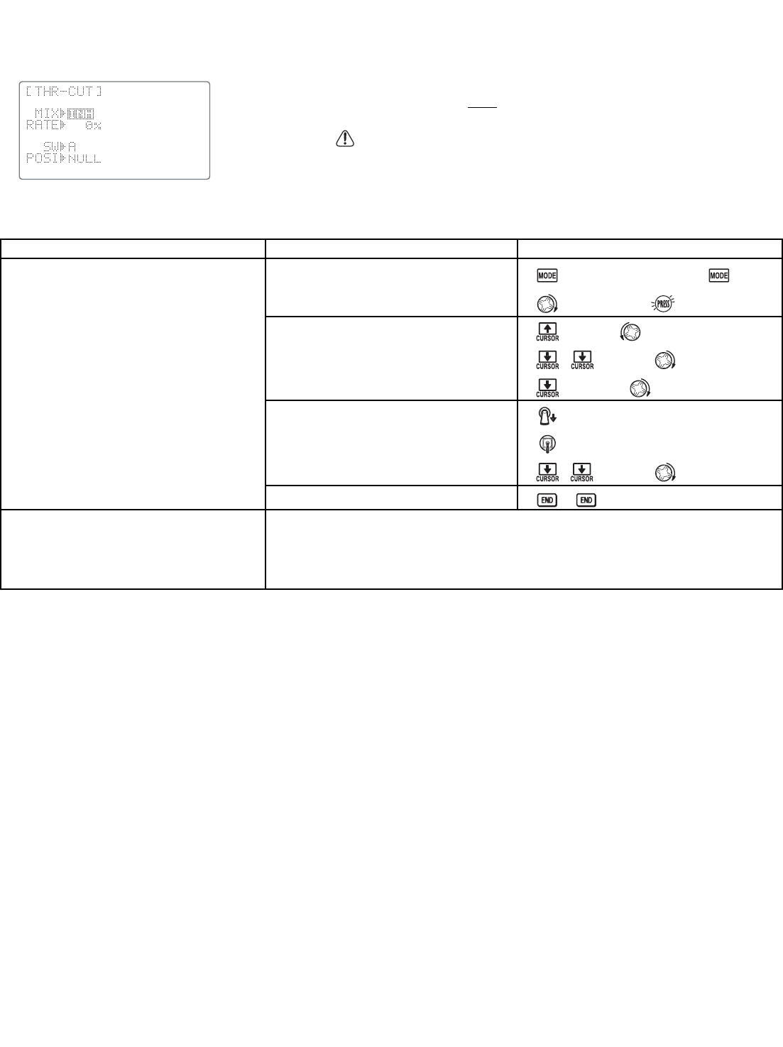
THR-CUT (specialized settings for helicopter specific
models) . . . . . . . . . . . . . . . . . . . . . . . . . . . . . . . .82
HELI-SPECIFIC ADVANCE MENU FUNCTIONS . . .83
THROTTLE HOLD . . . . . . . . . . . . . . . . . . . . . . . . . .83
THR-CURVE, PIT-CURVE and REVO. . . . . . . . . . . . . .84
Idle-ups . . . . . . . . . . . . . . . . . . . . . . . . . . . . . . . .85
Trims/offset . . . . . . . . . . . . . . . . . . . . . . . . . . . . .86
Delay . . . . . . . . . . . . . . . . . . . . . . . . . . . . . . . . .87
Hovering setups . . . . . . . . . . . . . . . . . . . . . . . . . .88
Gyros and governors . . . . . . . . . . . . . . . . . . . . . .89
Glossary . . . . . . . . . . . . . . . . . . . . . . . . . . . . . . . . . . . .94
Note that in the text of this manual, beginning at this point,
any time we are using a feature’s specialized name or
abbreviation, as seen on the screen of the 9C, that name,
feature, or abbreviation will be exactly as seen on the radio’s
screen, including capitalization and shown in a DIFFERENT
TYPE STYLE for clarity. Any time we mention a specific
control on the radio itself, such as moving SWITCH A, KNOB
VR(B), or the THROTTLE STICK, those words will be
displayed as they are here.
2
TABLE OF CONTENTS