744658
2
Zoom out
Zoom in
Previous page
1/24
Next page
*PGI only for France, Belgium & Switzerland
Operating manual
COMO II RAO
COMO II PGI*
2
TABLE OF CONTENTS
1. PREFACE 3
Explanations to symbols .................................................................................................................................................................................................. 3
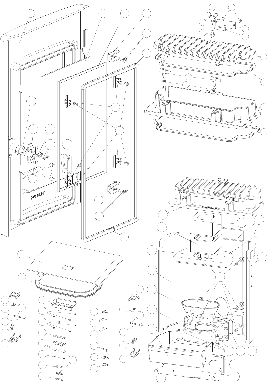
Spare part overview exploded diagram ............................................................................................................................................................4
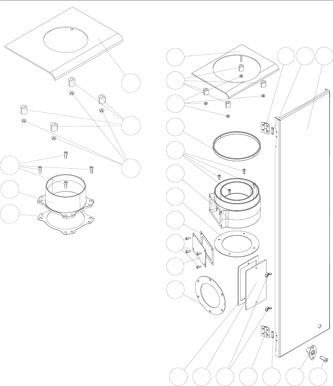
Spare part overview exploded diagram RAO/PGI ....................................................................................................................................6
Spare part overview article numbers ....................................................................................................................................................................7
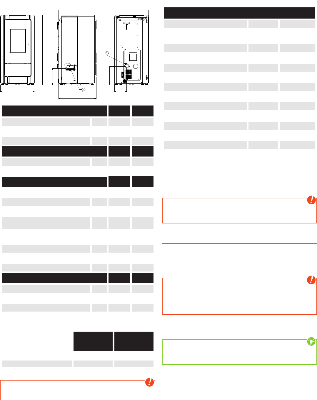
Dimensions of COMO II RAO/PGI .............................................................................................................................................................................. 8
Amount of Fuel .......................................................................................................................................................................................................................... 8
Technical data for COMO II RAO/PGI ...................................................................................................................................................................8
Packaging ...................................................................................................................................................................................................................................... 8
Electrical connection ........................................................................................................................................................................................................... 8
2. INSTALLING THE STOVE 9
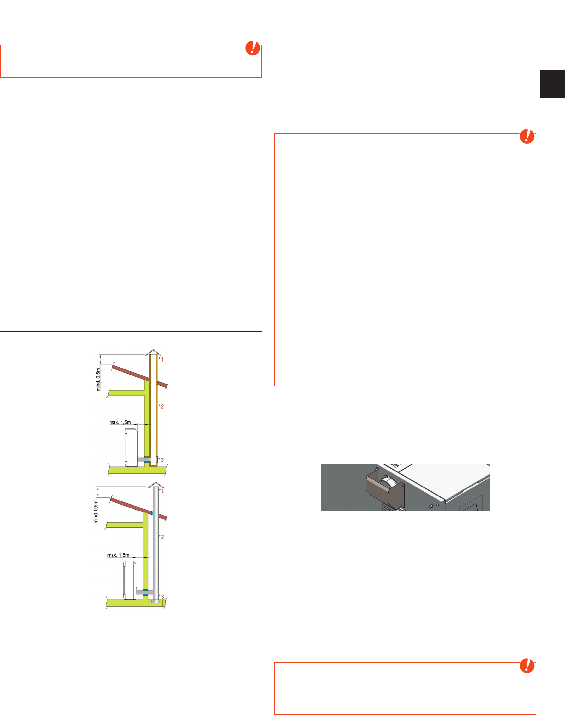
Connection to the chimney ........................................................................................................................................................................................... 9
Connecting to a steel chimney ..................................................................................................................................................................................9
Combustion air ......................................................................................................................................................................................................................... 9
Feeding in external combustion air ....................................................................................................................................................................... 9
3. IMPORTANT INFORMATION 10
General warning and safety information .......................................................................................................................................................10
First heating ...............................................................................................................................................................................................................................10
Safety distances ....................................................................................................................................................................................................................10
Prior to set up .............................................................................................................................................................................................................................11
The correct chimney connection .............................................................................................................................................................................11
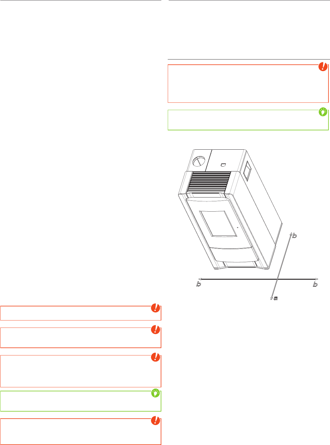
Convection air conduction ............................................................................................................................................................................................11
4. BRIEF INFORMATION ON FUEL  PELLETS 12
What are pellets? ....................................................................................................................................................................................................................12
Wood pellet specification according to ENplus – A1 .............................................................................................................................12
Pellet container refilling during operation ......................................................................................................................................................12
Pellet storage .............................................................................................................................................................................................................................12
5. TECHNOLOGY AND SAFETY FUNCTIONS 13
Operating comfort ............................................................................................................................................................................................................... 13
Top efficiency - lowest emissions ........................................................................................................................................................................... 13
DAR - Dynamic Air Regulation .................................................................................................................................................................................. 13
Pressure monitoring ........................................................................................................................................................................................................... 13
Low-temperature shutdown ....................................................................................................................................................................................... 13
Electrical excess current protection ................................................................................................................................................................... 13
Automatic cleaning cycle .............................................................................................................................................................................................. 13
Component monitoring .................................................................................................................................................................................................. 13
Auger motor monitoring ................................................................................................................................................................................................. 13
Power failure (during heating) .................................................................................................................................................................................. 13
Power failure (during the initial stage) .............................................................................................................................................................. 13
6. ASSEMBLY  DISASSEMBLY CASING 14
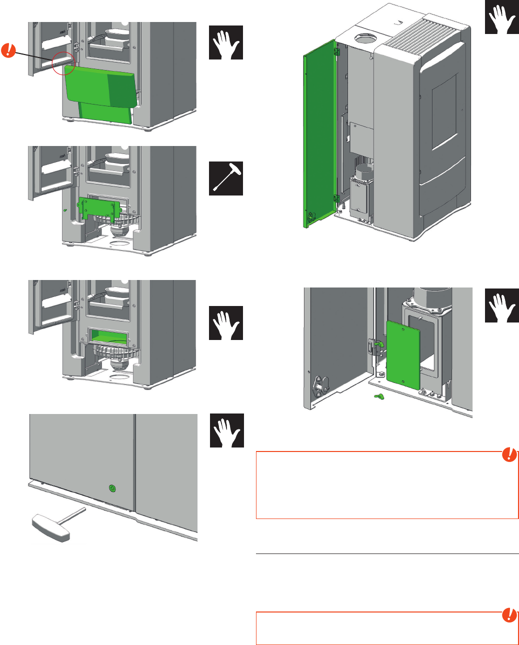
Rear side panel ....................................................................................................................................................................................................................... 14
Stone panels ..............................................................................................................................................................................................................................14
7. COMFORT OPTIONS 15
Room sensor, Radio room sensor ............................................................................................................................................................................15
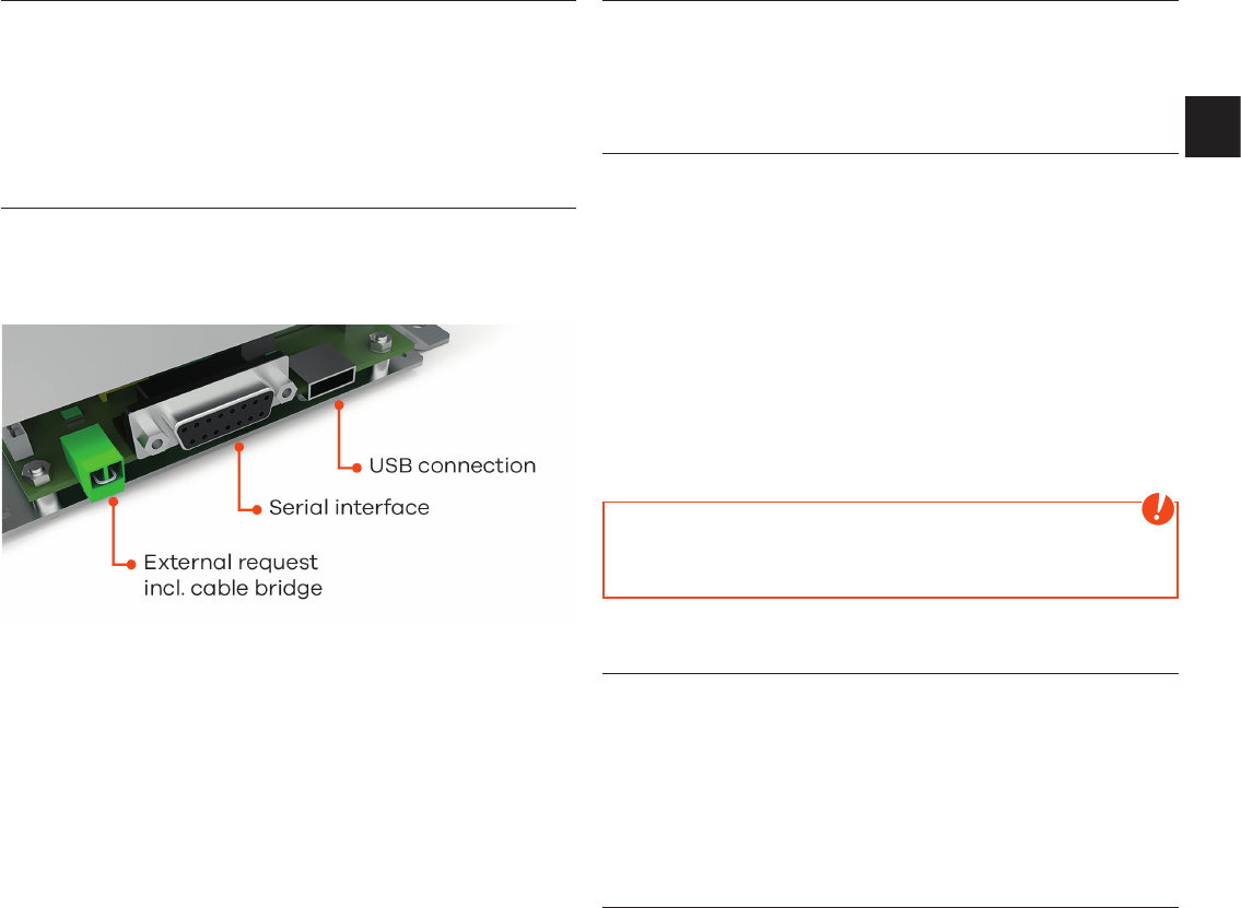
Interface for various options .......................................................................................................................................................................................15
External room thermostat .............................................................................................................................................................................................15
External connection cable bridge ..........................................................................................................................................................................15
Option firenet ............................................................................................................................................................................................................................15
RIKA VOICE ..................................................................................................................................................................................................................................15
|3
2
EN
8. MAINTENANCE 16
Open the combustion chamber door ................................................................................................................................................................ 16
Empty the ash drawer ...................................................................................................................................................................................................... 16
Cleaning the flame temperature sensor ......................................................................................................................................................... 16
Cleaning of the burn pot - daily .............................................................................................................................................................................. 16
Cleaning the door glass .................................................................................................................................................................................................. 16
Cleaning painted surfaces ........................................................................................................................................................................................... 16
9. CLEANING 17
Cleaning the convection air openings ...............................................................................................................................................................17
Combustion air - intake ................................................................................................................................................................................................... 17
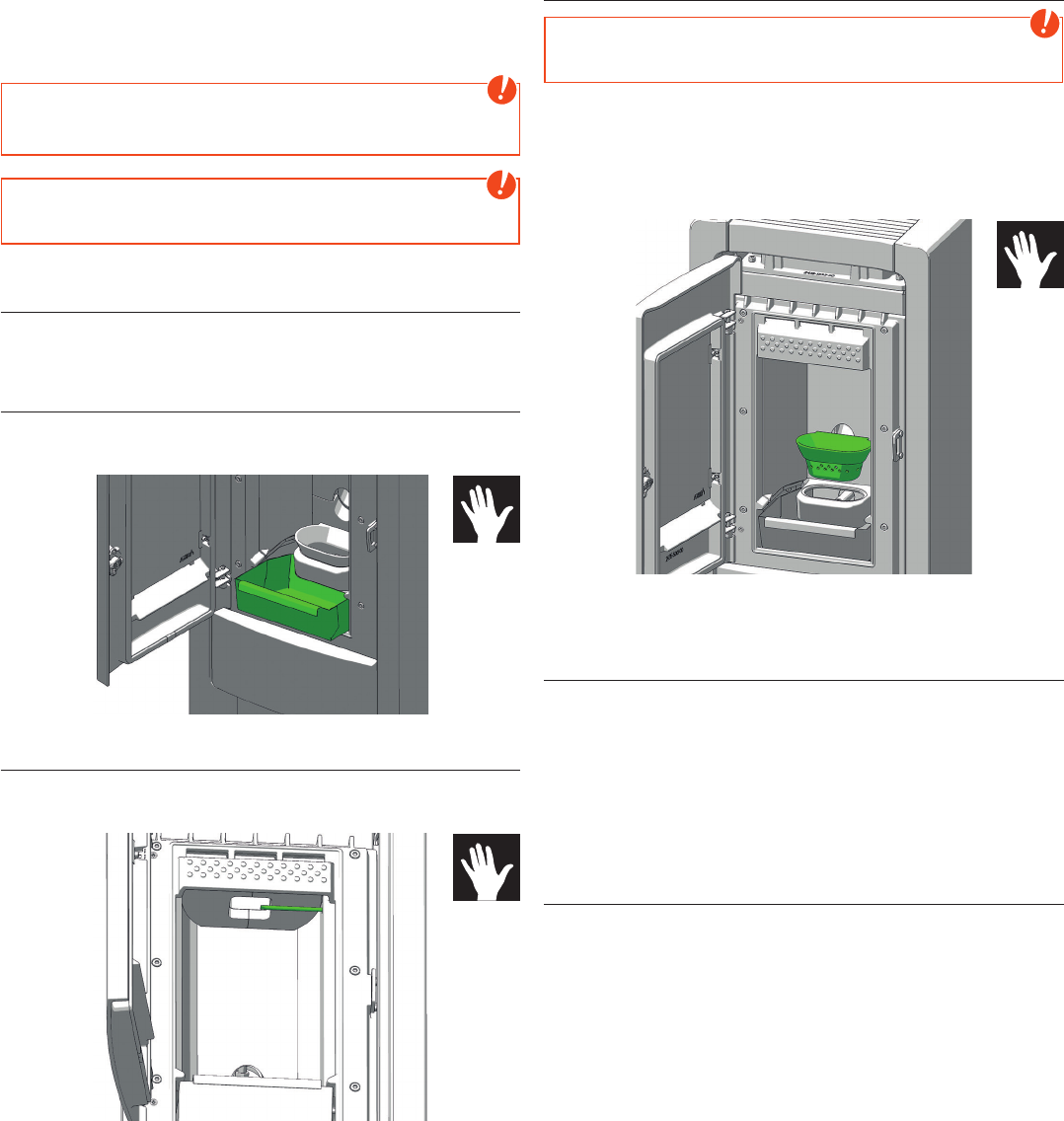
Cleaning the pellet container ..................................................................................................................................................................................... 17
Bearings .........................................................................................................................................................................................................................................17
Checking seals ......................................................................................................................................................................................................................... 17
Cleaning the flue gas channels and flue gas collecting duct ......................................................................................................17
Cleaning the flue pipes ................................................................................................................................................................................................... 18
10. PROBLEMS  POSSIBLE SOLUTIONS 19
Problem 1 ....................................................................................................................................................................................................................................... 19
Problem 2 ...................................................................................................................................................................................................................................... 19
Problem 3 ..................................................................................................................................................................................................................................... 19
11. INSTRUCTIONS FOR COMMISSIONING PROTOCOL 20
Operator instruction .........................................................................................................................................................................................................20
12. GUARANTEE CONDITIONS 22
13. WARRANTY CONDITIONS 22
1. PREFACE
Explanations to symbols
...Important note
#8
...Hex #8
#10
...Hex #10
...Useful tip ...Manually
#4
...Allen key 4
4
Spare part overview exploded diagram
66
65
54
54
72
71
70
53
73
58
58
56
56
55
55
57
57
68
62
69
64
67
62
63
61
62
63
59
60
32
31
28
21
33
34
22
35
36
37
23
30
29
24
25
27
26
20
15
1
6
9
3
2
7
8
4
4
10
12
13
11
5
5
5
45
50
51
47
42
46
41
40
49
43
44
48
|5
4
EN
75
75
84
84
83
82
93
80
98
80
80
85
86
89
90
99
95
94
92
76
76
97
96
77
80
79
78
77
80
87
115
117
119
118
120
121
122
113
110
109
111
112
125
124
123
108
106
107
103
126
130
129
128
104
103
100
101
102
105
114
116
127
6
140
159
158
157
151
151
153
152
152
155
154
144
145
146
143
141
142
147
150
149
148
160
161
162
163
164
165
Spare part overview exploded diagram RAO/PGI
|7
6
EN
Spare part overview article numbers
Note: Please consider the powdercoated parts can differ slightly in colour and colour effects though they are elaborated in high quality.
Nr. Art.Nr. Description
1 Z37899 Front door
B18638 Front door assy
2 Z33701 Front door glass
3 N103693 Flat seal black 8x2
4 L01448 Hinge
5 N111950 Hexagonal screw M05x10
6 N112551
Round sealing strip grey
D11 (1m)
7 L03681 Glass holder
8 N112075 Allen screw
9 N112603 Glass fabric tape adhesive
10 Z37918 Locking bolt
11 L01450 Closure plate
12 L01449 Lock tongue
13 N109985 Allen screw
14 L01998 Closure flap
15 N110032 Hexagonal screw
20 L03424 Ash drawer
21 B17529 Fire trough holder
22 Z35804 Recess
23 Z37318 Firebrick lining front left
24 Z37882 Baffle plate left
25 Z37905 Exhaust duct
26 B18332
Cover combustion
chamber assy
27 Z37237 Exhaust duct
28 Z37142 Cast rear panel
29 Z37928 Baffle plate right
30 Z37319 Firebrick lining right
31 N112170 Hexagon socket screw
32 Z37143 Casting rear wall bottom
33 N103066
Round sealing strip black
D06
34 N111846 Hexagon socket 06x12
35 N100474 Sealing cord black D08
36 L01437 Cleaning opening
B16191 Cleaning opening assy
37 N103964 Hexagonal screw
40 N105378 Hexagonal nut
41 B18352 Hinge black
42 N112386 Swing bolt
43 N112389 Washer
44 N112387 Wing nut
45 N111799 Hexagonal screw
46 Z36922 Holder plate
47 N112390 Cylindrical pin
48 B18331 Cleaning opening assy
49 N100476 Sealing cord black D10
50 Z37131
Combustion chamber
cover
51 N107048 Sealing cord black D10
53 L03691 Bottom hinge left
54 N112240 Self-tapping screw
55 N110501 Circlips
56 Z34854 Hinge shaft
57 N112297 Self-locking nut
58 L02498 Hinge
59 N112600 Container seal
Nr. Art.Nr. Description
60 LB00793 Container lid RAO/PGI
61 Z36111 Cover
62 N112144 Washer
63 N112700 Hexagonal nut M03
64 L01446 Lock washer
65 N112085
Hexagonal countersunk
screw
66 L01502 Lock washer
67 N110461 Double ball catch
68 N111732 Magnetic switch top part
69 N112143 Hexagonal nut M03
70 N112165 Hexagon socket screw
71 N111733
Magnetic switch bottom
part
72 L01445 Switch spacer
73 L03692 Bottom hinge right
75 Z34366 Bolt stone
76 Z37809 Support pad, silicone
77 N108687 Cylinder screw
78 Z38129 Stone holder left
79 Z37932 Soapstone left
Z37933 Stone white left
80 N112240 Self-tapping screw
82 N112134 Self-tapping screw
83 Z37910 Centre sleeve
84 N112490 Levelling screw black
85 Z37901 Front panel top
86 N111948 Hexagon socket screw
87 LB00777 Cleaning opening assy
89 B18640 Convection fin assy
90 N112190 Hexagon socket screw
92 N112484 Door opener
93 L03644
Side casing panel right
back
94 N112502 Self-tapping screw
95 Z35691 Spring plug
96 Z38128 Stone holder right
97 Z37930 Soapstone right
Z37931 Stone white right
98 L01438 Front carrier
99 Z37900 Bottom front panel
100 B16561 Mainboard USB11
101 B16030
Additional motherboard
for motor, incl. cable
102 N112102
Differential pressure
switch
103 N111911 Self-tapping screw
104 L03638 Holder plate
105 N112473
Differential pressure
sensor
106 B19087 Temperature sensor
107 L01954 Pressure bracket
108 B16053 Sensor tube
109 B17166 Ceramic ignition
110 Z36290 Seal for ignition
111 N100169 Washer
112 N111793 Self-tapping screw
113 Z36760 Pressure Pipe
114 N111551 Silicon hose
Nr. Art.Nr. Description
115 Z35183 Friction bearing Di10
116 B16574 Touch-display plug-in
117 B12301 Auger
118 Z35182 Friction bearing Di16
119 Z31674 Centring plate
120 L00797 Motor holder plate
121 N104976 Self-tapping screw
122 Z18997 Rubber buffer
123 N112499 Setscrew with pin
124 Z11915 Lock ring conveyer screw
125 N112030 Screw motor, stepless
126 B16155 Induced draft fan housing
B15913 Induced draft fan assy
127 Z38188 IEC mains socket
128 N105627 Self-tapping screw
129 N110573 Hexagonal screw
130 N111581 Induced draft fan motor
Version RAO/PGI
140 N112015 Flue pipe sealing
141 L03376 Cover air supply
142 N111909 Hexagon socket screw
143 Z37332 Seal
144 Z38122 Seal
145 Z37190 Flange
146 N112694 Hexagon socket screw
147 N112462 Sealing
148 N112142 Flange nut
149 N112530 Spacer
150 LB00795 Cover PGI
151 Z37907 Hinge
152 L03709 Retaining plate
153 LB00791
Side casing panel back left
RAO/PGI
154 Z37903 Locking bolt
155 LB00845 Closure bearing
157 N112077 Wing nut
158 Z37449 Cleaning opening
159 Z37448 Seal
160 Z37830 Pipe adapter seal
161 Z37844 Pipe adapter
162 N112694 Hexagon socket screw
163 LB00794 Cover assy, top flue outlet
164 N112530 Spacer
165 N112142 Flange nut
B18316 Wiring harness
Z38075
Cable for differential
pressure sensor
Z35018
Cable for touch-screen
1,25 m
N111604 Fuse 2,5 A
Z38190 Mains plug
Z34841
Cable for additional
motherboard
E16473 Sealing kit
8
Dimensions of COMO II RAO/PGI
505
556
1033
178
274
97
240
170
100
60
Dimensions RAO PGI
Height [mm] 1033 1033
Width [mm] 505 505
Corpus depth [mm] 555 555
Weight
Weight without shell [kg]  
Weight with stones [kg]  
Flue pipe connection
Flue pipe outlet [mm]  
Connection height [mm]  
Original angle pipe total depth [mm] - -
Original angle pipe distance to rear
wall
[mm] - -
Depth from rear wall to middle of flue
pipe
[mm]  
Original angle pipe side distance [mm]  
Rear connection height [mm] - -
Rear connection side distance [mm] - -
Fresh air connection
Diameter [mm]  
Connection height [mm]  
Side distance [mm]  
Amount of Fuel
Nominal
load
Part load
Amount of fuel ~, kg* ~, kg*
Burn time at full pellet hopper ~18 h* ~57 h*
*Practical values may vary depending on pellet quality.
Note
Pellet consumption depends on the size of the pellets. The larger
the pellets, the slower the feed and vice versa.
Technical data for COMO II RAO/PGI
Technical data
Heating power range [kW] , - 
Room heating capacity (depending
on house insulation)
[m]  - 
Fuel consumption [kg/h] till ,
Pellet container capacity* [l]/[~kg] /~
Electric supply [V]/[Hz] /
Average electrical input [W] ~
Fuse [A] , AT
Efficiency [%] ,
CO
2
[%] ,
CO-emission on 13% OO
2
[mg/m
N
] 
Dust emission [mg/m
N
]
Exhaust [g/s] ,
Exhaust temperature [°C] ,
Chimney draft requirement [Pa]
*The capacity in kg may deviate due to different pellet bulk
densities.
The owner of small firing systems or the person authorised for the
small firing system is to keep the technical documentation and is to
submit it to the authorities or the chimney sweep on request.
Note
Please observe the national and European standards as well as
local regulations concerning the installation and operation of
firing installations!
Packaging
Your first impression is important to us!
The packaging of your new stove provides excellent protection
against damage. However damage to the stove and accessories
may still occur during transport.
Note
Therefore please check your stove on receipt for damage and
completeness! Report any deficiencies to your dealer immediately!
Pay particular attention during unpacking that the stone panels
remain intact. Scratches to the material can easily occur. Stone
panels are excluded from the warrant.
The packaging of your new stove is environmentally neutral to a
great extent.
Tip
The wood used in the packaging has not been surface treated.
The cardboard and film (PE) can be disposed of via the municipal
waste collection for recycling.
Electrical connection
The stove is supplied with an approx. 2 m long connecting cable
with a Euro-plug. This cable is to be connected to a 230 Volt / 50 Hz
socket. The average electrical power consumption is some 20 Watt in
heating operation. And approx. 150 Watt during automatic ignition.
The connection cable must be laid so that there is no contact to any
sharp edges or hot surfaces of the stove.
|9
8
EN
2. INSTALLING THE STOVE
Note
Assembly may only be performed by authorised specialist
companies.
Note
Please observe the regional safety and building regulations. Please
contact your master chimney sweep in this context.
Note
Only use heat-resistant sealing materials as well as corresponding
sealing strips, heat-resistant silicon and rock wool.
Note
Also take care that the flue does not project into the free cross-
section of the chimney.
Note
In case of room-air independent operation the stove pipe
connections must be tightly sealed permanently. Use a heat-proof
silicon to position the stove pipe on the conical supports of the flue
tube nozzles and for insertion in the chimney flue lining.
Note
The stove should not be pushed on unprotected floors.
Tip
Strong corrugated cardboard, cardboard or e.g. old carpet is useful
to assist assembly and as a base. The stove can also be pushed on
this cardboard or carpet.
We recommend original flue pipes from RIKA for proper connection.
Connection to the chimney
Q The device must be connected to a flue that is approved for solid
fuels and is insensitive to moisture. The moisture insensitivity may
vary if the flue calculation results in a dry operation. The chimney
must have a diameter of min. 100 mm for pellet stoves and
130 mm -150 mm for log wood stoves depending on the diameter
of the flue pipes.
Q Avoid long flue pipes to the chimney. The horizontal length of the
flue pipe should not exceed 1.5 metres.
Q Avoid to many bends of the flue gas pipes. There should not be
more than 3 bends in the exhaust pipe.
Q Please use a connection with a cleaning opening.
Q Connections must be made of metal and must meet the
requirements of the standard (install the connections airtight).
Q Before installing a chimney calculation must be made. The
evidence must be performed for single occupancy to EN13384-1
and EN13384-2 for multiple occupancy.
Q The maximum draft of the chimney should not exceed 15 Pa.
Q The derivation of the flue gases must be guaranteed even during
a temporary power outage.
Note
If connecting to multiple connection chimneys and depending on
country regulations, additional safety equipment is required. Your
local chimney sweep will advise you in this case.
Note
Be sure to prevent condensed water from entering via the flue
connection. You may need to have a condensate ring installed -
ask your chimney sweeping expert for more information. Damages
caused by condensate are excluded from manufacturer’s warranty.
Connecting to a steel chimney
The connection must be calculated and shown with EN13384-1
and EN13384-2.
Use only insulated (double) stainless steel tubes (flexible aluminum
or steel tubes are not permitted).
An inspection door for regular inspection and cleaning must be
present.
The flue pipe connection to the chimney has to be air-tight.
Combustion air
Every combustion process requires oxygen from the surrounding air.
This so-called combustion air is removed from the living are in the
case of individual stoves without external air connections.
This air removed must be replaced in the living space. Very tightly
sealed windows and doors in modern flats may mean that too little
air replaces that used. The situation also becomes problematical due
to additional venting in flats (e.g. in the kitchen or WC). If you cannot
feed in external combustion air, then air the room several times a
day to prevent negativce pressure in the room or poor combustion.
Feeding in external combustion air
only for devices which are able to run in room-air independent
operation.
Q Combustion air must be fed to the stove from outside via a sealed
pipe for operation independent of the room air. According to
EnEV, it must be possible to shut off the combustion air pipe. The
open/closed setting must be clearly recognisable.
Q Connect at the air intake either a pipe Ø 125 mm for log wood and
combi stoves, or Ø 50 mm or Ø 60 mm for pellet stoves. Fix it with
a hose clamp (not included!). At pellet stoves with longer intake
pipes than 1 m the diameter should be increased to 100 mm. (see
RIKA range).
Q To ensure sufficient air intake, the intake pipe should not exceed
max. 4 metres and have max. 3 bends.
Q If the line leads outside it must have a windbreak.
Q In extreme cold pay attention to icing on the air intake opening
(check).
Q It is also possible to suction in combustion air directly from
another sufficiently vented room (e.g. cellar).
Q The combustion air pipe must be tightly connected (adhesive or
cement) permanently to the air nozzles of the stove.
Q If you do not use the stove for a long time, please close the
combustion air intake to prevent the stove from moisture.
Note
Please note that problems may arise due to updrafts in the case
of combustion air supply from an integrated chimney ventilation
shaft. If the combustion air flowing downwards is heated it may
rise and thus counter the chimney with a resistance which in turn
reduces the negative pressure in the combustion chamber. The
chimney manufacturer is to guarantee that the resistance for the
combustion air is a maximum 2 Pa even in the least favourable
operating state of the chimney.
If one or more of these conditions does NOT apply, the result is poor
combustion in the stove and negative pressure in the installation
room.
10
3. IMPORTANT INFORMATION
General warning and safety information
Observance of the introductory general warning information is
imperative.
Q Read the entire manual thoroughly before installing and putting
the stove into service. Observe the national provisions and laws
as well as the regulations and rules applicable locally.
Q RIKA stoves should only be installed in rooms with normal humidity
(dry areas according to VDE 0100 Part 200). The furnaces are not
splash water protected and may not be installed in wet areas.
Q Only approved transport equipment with sufficient load carrying
capacity may be used with your heating appliance.
Q Your heating appliance is not suitable for use as a ladder or
stationary scaffolding.
Q The burning of fuel releases heat energy that lead to extensive
heating of the stove surfaces, doors, door and operating handles,
glass, flue pipes and possibly the front wall. Refrain from touching
these parts without appropriate protective clothing or equipment
e.g. heat-resistant gloves or means of operation (operating
handle).
Q Make your children aware of this particular danger and keep
them away from the stove during heating.
Q Only burn approved heating materials.
Q The combustion or introduction of highly flammable or explosive
materials such as empty spray cans etc. in the combustion
chamber and storing them near the stove is strictly prohibited
due to the danger of explosion.
Q No light or inflammable clothing is to be worn when post-heating.
Q Use the heat-resistant gloves supplied to open the doors of your
stove.
Q Make sure that no embers fall out of the combustion chamber
onto inflammable material.
Q Placing non-heat resistant objects on the stove or near it is
prohibited.
Q Do not place clothing on the stove to dry.
Q Laundry racks etc. must be placed at a sufficient distance to the
stove – ACUTE DANGER OF FIRE!
Q When your stove is burning, the use of highly inflammable and
explosive materials in the same or adjacent rooms is prohibited.
Q If the stove is heated in continuous operation, the cleaning
intervals are shorter. Increased wear, especially of the thermally
stressed parts, is the result. Please therefore strictly follow the
requirements for cleaning and maintenance!
Note
Waste and liquids may not be burnt in the stove!
Note
To prevent your stove from overheating of the internal components,
do never cover the convection fins!
Note
CAUTION when filling the pellet container. The opening of the pellet
container is sufficiently dimensioned to ensure easy filling. Take
great care that no pellets drop to the convection fins and the hot
stove body. This can cause a lot of smoke.
Tip
Therefore we recommend refilling the pellet container at a cold
stove.
Note
Your stove will expand and contract during the heating and cooling
phase. This can sometimes lead to slight bending or cracking
noises. This is normal and is no reason for a complaint.
First heating
The stove body, just as various steel parts, cast iron parts and the
flue pipes are painted with a heat resistant paint. During the first
heating the paint dries out completely. This may cause a slight smell.
Touching or cleaning the painted surfaces during the curing should
be avoided. The hardening of the paint is finished after the first
heating with high power.
Safety distances
Note
1. To non-combustible objects
a > 40 cm, b > 10 cm
2. To combustible objects and reinforced concrete load-bearing
walls
a > 80 cm, b > 10 cm
Tip
Please observe a minimum distance of 20 cm behind and sideways
the stove for maintenance.
|11
10
EN
Prior to set up
Floor bearing capacity
Ensure that the substructure is capable of bearing the weight of the
stove prior to set-up.
Note
No modifications may be made to the firing installation. This also
leads to loss of warranty and guarantee.
Floor protection
A glass, sheet steel or ceramic plate is recommended, if the floor is
combustible (wood, carpet, etc.). Please observe the respective local
regulations and rules.
Flue pipe connection
Q Flue pipes pose a particular source of hazard regarding gas leaks
and fire. Get the advice of an authorised specialist company for
the layout and assembly.
Q Please observe the corresponding installation guidelines for walls
panelled with wood when connecting your flue pipes to the stove.
Q Observe the formation of flue gas (atmospheric inversion) and
draughts when the weather is unfavourable.
Q Infeed of too little combustion air can lead to smoke in the rooms
or to flue gas leaks. Hazardous deposits in the stove and chimney
may also occur.
Q If flue gas escapes, let the fire burn out and check whether all the
air inlet openings are free and the flue gas pipes and the stove
pipe are clean. If in doubt notify the master chimney sweep since
draught malfunctions may be connected to your chimney.
The correct chimney connection
There are several ways to connect your stove to the chimney, eg:
*1
*2
*3
*1
*2
*3
1) wind break, 2) chimney, 3) inspection opening
For the selection of the connection and to ensure a proper connection
between the stove and chimney, please read the guide „INSTALLING
THE STOVE“ or ask your local chimney sweep.
Stoves type 1 (BA 1):
Q Suitable for multiple occupancy. (Note the different country
regulations.)
Q These may only be operated with the combustion chamber door
closed.
Q The combustion chamber door is to be kept closed when the
stove is not in operation.
Q Fouling of the chimney i.e. deposits of highly inflammable materials
such as soot and tar and subsequently fire in the chimney may
occur if the chimney is miscalculated and dimensioned wrong.
Q If this occurs, disconnect the mains plug. Phone the fire brigade
and get yourself and other residents out of harm’s way.
Note
Your pellet stove has been tested as a room-air independent stove
according to EN14785. It can be operated room air dependent or
room air independent.
ROOM-AIR INDEPENDENT OPERATION:
The stove is certificated for type FC62x of the approval principles
for the inspection and evaluation of ambient air independent
fireplaces specified by the Deutsches Institut für Bautechnik (DIBT)
(German Institute for Building Technology). Thanks to an air-tight
configuration of the air supply line and flue pipes the stove may be
operated in air-tight rooms and in rooms with room-air installations
(e.g. controlled ventilation and venting systems, extractors etc.).
ROOM-AIR DEPENDENT OPERATION:
In combination with room-air installations (e.g. controlled
ventilation and venting systems (extractors etc.) it must
be ensured that the stove and the room air system are
monitored and safeguarded mutually (e.g. via a differential
pressure controller). The combustion air infeed of approx.
20 m
3
/h must be ensured.
Please observe the respective local regulations and rules in
consultation with your master chimney sweep. For changes after
the printing of this manual, we can not assume any liability. We
reserve the right to change without notice.
Convection air conduction
Only for stoves with MultiAir
The stove is delivered with a cover on the convection air outlet to
prevent direct heat to the wall.
Operation without this cover or without attached convection pipes is
not allowed. If you do though no warranty and no liability is accepted
for damage.
Q The amount of air and temperature is designed to heat one
additional room.
Q Note the regional specific fire safety regulations and clarify the
connection situation with the competent authority
Q The max. temperature of the convection air is 180° C at the air
outlet.
Q The convection air should be as short as possible.
Q Keep the number of deflections as small as possible.
Note
Please pay attention to the national and country-specific building
and fire regulations when connecting the convection air pipes.
Installation and assembly must be performed by a trained
specialist only.
example
12
4. BRIEF INFORMATION ON FUEL  PELLETS
What are pellets?
Wood pellets are a standardised fuel. Every manufacturer must
adhere to certain conditions in order to enable flawless, energy-
efficient heating. Pellets are made from wooden waste, from sawmills
and planning workshops, as well as from residue from forestry
operations. These starting products are crushed, dried, and pressed
into pellet fuel without any bonding agent.
ENplus – Pellets
This ENplus standard sets benchmarks in the European pellet
market. The traceability of pellets is ensured thanks to the use of
identification numbers. The pellet manufacturers’ production
facilities and manufacturing processes are reviewed every year.
A quality assurance system ensures the pellets comply with the
requirements of the new standard and that the conditions for
trouble-free heating are guaranteed
DE 000
Wood pellet specification according to
ENplus – A1
Parameter Measure ENplus-A1
Diameter mm  (±)
)
Length mm ,–
)
Buld density kg/m  
Calorific value MJ/kg  ,
Water content Ma.-%  
Fine fraction (< 3,15 mm) Ma.-%  
Mechanical rigidity Ma.-%  ,
)
Ash content Ma.-%
)
 ,
Ash softening temperature (DT) °C  
Chlorine content Ma.-%
)
 ,
Sulphur content Ma.-%
)
 ,
Nitrogen content Ma.-%
)
 ,
Copper content mg/kg
)
 
Chrome content mg/kg
)
 
Arsenic content mg/kg
)
 
Cadmium content mg/kg
)
 ,
Mercury content mg/kg
)
 ,
Lead content mg/kg
)
 
Nickel content mg/kg
)
 
Zinc content mg/kg
)
 
1) in an anhydrous state
2) diameter must be specified
3) a maximum of 1 % of the pellets may be longer than 40 mm,
max. length is 45 mm
4) the limit value of ≥ 97,7 Ma.-% applies when conducting
measurements with a lignotester (internal control)
Your pellet stove is only approved for the burning of pellets of tested
quality. Please ask your pellet stove dealer for tested fuel and a list of
monitored fuel manufacturers.
Note
Only burn pellets that have been inspected according to
ENplus - A1. Using poor quality or prohibited pellet fuel will have a
negative effect on the function of your pellet stove and can also
lead to the warranty becoming null and void, as well as the product
liability connected with this.
Note
Burning straw, maize, woodchips etc. is not permitted! Observe
waste incineration legislation! Non-observance of these
regulations makes void all warranty and guarantee claims and
may impair the safety of the unit!
Pellet container refilling during operation
Note
CAUTION when filling! Avoid direct contact between the plastic
bag and the hot stove. Immediately remove all pellets that have
fallen on the hot stove or next to the container!
We recommend always having a suitable amount of pellets in the
container to prevent the fire from extinguishing due to a lack of fuel.
Check the level frequently. However the container lid should be kept
closed, except during filling.
If you refill the container during operation (open the container lid),
the fan will speed up and the pellet auger will stop; operation will only
be continued once the container lid is closed again (see operating
instruction TOUCH DISPLAY)
Pellet container capacity: (see TECHNICAL DATA)
Pellet storage
In order to guarantee problem free burning of the wooden pellets, it
is imperative necessary to store the fuel as dry as possible and free
from impurities.
Pellets should not be kept in sacks outdoors or stored in a manner
where they are exposed to the environment. This can lead to
blockages in the screw conveyor.
Note
Screw stoppers are excluded from the warranty.
|13
12
EN
5. TECHNOLOGY AND SAFETY FUNCTIONS
The technological advances in your new combi stove are the result of
years of testing and practical experience. The practical advantages
of your pellet stove are convincing:
Operating comfort
All functions can be regulated using the integrated touch display.
The user-friendly interface permits extremely easy operation.
Top efficiency - lowest emissions
All processes in the stove are fully automated. The parameters
Q Air control
Q Temperature monitoring
Q Pellet dosing
are continuously optimised. This guarantees optimum combustion.
The result are low consumption and very good exhaust gas values
that even undercut the legally permitted limits.
Note
Due to the automated control, you may hear flame fluttering,
falling pellets and sounds from the activation of the electronic
components during operation.
DAR - Dynamic Air Regulation
A differential pressure sensor in the supply air system measures the
air flow. The fan speed is adjusted automatically and guarantees
optimum combustion.
The air pipe of an external supply air pipe can also be monitored in
this way.
Pressure monitoring
The negative pressure in the combustion chamber is continuously
monitored during operation. Below a defined threshold, a correct
operation can not be guaranteed and the unit will switch off with the
fault message „NOT ENOUGH LOW PRESSURE“ for safety reason.
Note
If the stove is used in a habitation together with a kitchen hood or
a ventilation (WC) it might happen that the built-in pressure switch
stops the stove. If using the hood make sure that an adequate
supply of air is ensured.
Low-temperature shutdown
The unit switches off if the stove cools below a minimum temperature.
This switch-off may occur if pellet ignition is delayed.
Electrical excess current protection
The stove has a main fuse (at the rear) to protect against excess
current.
Automatic cleaning cycle
The speed of the flue gas fan is increased every hour for a short
period to blow ash from the burn pot, increasing the operational
safety. The status indicator CLEAN appears on the display.
Only for stoves with turning grids:
Every 6 hours (interval adjustable) an additionally automatic big
cleaning cycle is performed. The stove stops, the automatic cleaning
tilts the grid and then re-ignites the stove. The status indicator BIG
CLEAN appears on the display continuously. The cleaning procedure
with tilting the grid is to convey ash and clinker from the burn pot
into the ash drawer.
Note
This additional function does not replace a manual cleaning
as described in CLEANING and MAINTENANCE, as this is
absolutely necessary to do regularly.
Note
Due to the turning grid there is a certain generation of noise during
the automatic cleaning cycle (START or BIG CLEAN.
Component monitoring
All the electrical components used are continuously monitored
during operation. If a component is defective or can no longer be
actuated correctly, then operation is stopped and a warning or error
message is issued (see MANUAL TOUCH DISPLAY).
Auger motor monitoring
Too long or wet pellets as well as pellets with too high dust content
(see BRIEF INFORMATION ON FUEL PELLETS) can cause
so-called “auger jammers” in the auger channel. This may also
happen if the pellets accumulate in the burn pot and the backlog
reaches into the chute. The auger motor reacts in both cases with
an increased current consumption, which causes the error message:
DISCHARGE MOTOR BLOCKED. The stove will be stopped. Please call
the customer service immediately.
Power failure (during heating)
After a brief power failure, the operating functions that were set
before the power failure, continues. If the power failure lasts longer,
the stove goes to start phase if sufficient temperature or embers are
present. If the power failure lasts too long, the stove goes into the
stop phase. The flue gas fan continues to burn any pellet residues
(approximately 10 minutes). Then it will restart automatically.
Power failure (during the initial stage)
After a brief power failure the boot process continues. If the power
failure lasts longer, the stove is in the stop phase. The flue gas fan
continues to burn any pellet residues (approximately 10 minutes).
Then it will restart automatically.
14
6. ASSEMBLY  DISASSEMBLY CASING
Note
Only work on the unit when the mains plug has been disconnected
and the stove has cooled down completely.
Note
During assembly / dismantling do not allow objects (screws etc.) to
fall into the pellet container – they can block the screw conveyor
and damage the stove.
Note
During any conversion work, take particular care of your fingers
and any panels and stove attachments. Select soft bases to
prevent scratches to your living space furniture and stove panels.
Rear side panel
Open the pellet container lid. In this position it remains open.
Remove the 2 hex screws. Tilt the side panel slightly outwards and
disconnect the display cable. Lift side panel upwards.
Stone panels
Remove the lower front panel by lifting. The front panel is simply
hooked.
Open the pellet container lid. Loosen the 2 hexagon socket screws.
Slide the convection fins backwards and lift it up.
Remove the 2 hex screws. Tilt the side panel slightly outwards and
lift it straight up.
Repeat the process on second side.
Install the removed parts in reverse order.
#8
#4
#8
|15
14
EN
7. COMFORT OPTIONS
Room sensor, Radio room sensor
This option permits control of your stove via room temperature. You
can set both the room temperature and the heating times required.
A room temperature selected by you is observed during the heating
times.
Please see the operating instructions for the option room sensor and
wireless room sensor for more detailed information.
Interface for various options
for various options
The ROOM SENSOR and the WIRELESS ROOM SENSOR are to be
connected to the interface (stove rear) using the connection cable
supplied.
(condition as delivered)
External room thermostat
Your stove has an interface on the rear wall to which you can
connect a customary room thermostat. This requires a 2-pole cable
of 0.5 – 0.75 mm2 cross-section that you have to connect instead of
the cable bridge fitted for delivery.
External connection cable bridge
If the control of your stove is to be assumed by an external room
thermostat, you have to connect your external room thermostat (1)
instead of the standard integrated cable bridge (2).
The connected room thermostat can be operated in either MANUAL
or AUTOMATIC MODE. In both MODES, the current set heat output
is used, in AUTOMATIC MODE the heating times set at the stove
can also be activated.
You can see whether the external demand is currently activated in
the INFO main menu in submenu item Info - inputs.
If your stove receives an external demand to stop operation, it takes
approx. 5 minutes until it switches off. All further settings required to
your thermostat can be taken from the respective room thermostat
operating instructions.
Note
Operation is not possible unless either a cable bridge or an external
room thermostat is connected. The external demand has priority
over all operating modes (MANUALAUTOMATICCOMFORT).
Option firenet
Only for combination and pellet stoves with touch panel version
V2.16 or higher.
The firenet module connects your stove to the Internet. You can
operate the stove with any Internet-enabled device (tablet, PC,
Smartphone ...). So you retrieve the operational status, various
information and make your settings remotely.
For further information, please contact your dealer.
RIKA VOICE
for combi and pellet stoves with touch display, version V2.26 or
above, only and in combination with the RIKA Firenet module and
Amazon Alexa
RIKA VOICE allows you to control your RIKA stove by simply speaking
to it. Power on or off, switching between modes or adjusting the
preferred heat output or room temperature: a few words is all it takes!
More detailed information could be obtained at www.rika.at or from
your dealer.
16
8. MAINTENANCE
The frequency with which the stove requires cleaning and the
maintenance intervals depend on the fuel you use. High moisture
content, ash, dust and chips may more than double the maintenance
required. We would like to point out again that only tested and
recommended pellets may be used as fuel.
Note
Ash may contain embers – only place ash in sheet steel containers.
FIRE RISK! In a cold state, dispose it of in the household waste.
Note
We recommend at least once a year to have all maintenance
carried out by your RIKA dealer.
Open the combustion chamber door
To open or close the combustion chamber door use the included key.
This key can be stored on the back of the stove when not in use.
Empty the ash drawer
Empty the ash drawer regularly. The ash drawer is simply pulled
forward with the combustion chamber door open.
Cleaning the flame temperature sensor
Remove the dust deposits from the sensor at regular intervals. Use a
clean cleaning cloth or newspaper.
Cleaning of the burn pot - daily
Note
Clean the fire trough regularly. Only clean when cold, when embers
are extinguished!
Make sure that the air vents are not blocked with ash or clinker.
Remove the clinker using the supplied brush and vacuum the fire
trough. The fire trough can be easily cleaned inside the stove. After
removing the fire trough the area underneath can be vacuum-
cleaned.
Do not damage the ignition when cleaning with the brush. Vacuum
out the pipe of the ignition.
Cleaning the door glass
If necessary
The viewing window becomes coated in the case of solid fuels,
particularly with the very fine ash of wood pellets, light or dark
depending on the pellet quality (especially with low output). The
glass can be cleaned best with a moist cloth. Stubborn dirt can be
removed with a special cleaner available from your stove dealer.
Usual cleaners containing acid or solvents can be too harsh and
damage the glass.
Cleaning painted surfaces
If necessary
Wipe the painted surfaces with a damp cloth, do not scrub. Do not
use solvent-containing cleaners.
|17
16
EN
9. CLEANING
Tip
Your RIKA dealer will gladly advise you about their service and
maintenance offers.
Depending on pellet consumption, a message prompting cleaning of
the stove appears on the display in regular intervals. This message
can be acknowledged on the Touch Display, while continuing
operation. Perform a cleaning cycle at the next opportunity.
Subsequently, reset the counter in the SETTINGS menu / RESETS
submenu, as per operating instructions of TOUCH DISPLAY.
Tip
The message will only stop reappearing once you have reset the
feed volume in the SETTINGS / Resets menu.
Note
Your stove must be switched off and cooled before any maintenance
work is performed. Only work on the unit when the mains plug has
been disconnected.
Cleaning the convection air openings
Vacuum clean any dust deposits from the convection air openings
at regular intervals.
The stove should be cleaned thoroughly prior to the start of the
heating season to prevent excess odour.
Note
To prevent your stove from overheating of the internal components,
do never cover the convection fins!
Combustion air - intake
If necessary, please also clean the air intake with a hoover.
Note
Only when the stove is cold! You could vacuum out embers – FIRE
RISK!
Cleaning the pellet container
Do not refill the completely empty container immediately; remove
the residues (dust, chippings etc.) from the empty container. The unit
must be disconnected from the mains!
Bearings
(annually)
All built-in bearings (pellet screw) should be checked. Clean or
replace bearings depending on condition.
Checking seals
(annually)
Check the condition of the seals at least once a year. Repair or
replace seals depending on condition.
Note
Only intact seals ensure your stove works perfectly!
Tip
You will find the seals and sealing kit in the spare part overview.
Cleaning the flue gas channels and flue
gas collecting duct
The flue gas channels are situated beneath and beside the
combustion chamber.
Open the pellet container lid. Loosen the 2 hexagon socket screws.
Slide the convection fins backwards and lift them up.
Loosen the wing nut on the lid of the cleaning opening, tilting the
eyescrew sidewards. Open the lid as far as the stop.
Now clean the flues and baffles with the supplied brush. Vacuum the
combustion residues with a vacuum cleaner.
#4
18
Remove the lower front panel by simply lifting. The front panel is
simply hooked.
Remove the cleaning lid.
Vacuum the combustion residues off the flue gas collecting duct,
especially the area to the flue gas fan.
Open the rear side panel with the key for the ombustion chamber
door.
Unscrew the two wing nuts and remove the outer cleaning lid.
Vacuum the combustion residues off the flue gas collecting duct,
especially the area to the flue gas fan.
Install the removed parts in reverse order.
Note
Your stove may suck in false air via incorrectly sealed cleaning
covers; this air may lead to incomplete combustion in the fire
trough and thus piling up of pellets. DANGER of FIRE!
To ensure the proper operation of your pellet stove, replace any
defect (porous, frayed) seals after cleaning and maintenance.
Cleaning the flue pipes
(annually)
Remove the flue pipes. Inspect and clean the chimney connection.
Brush off any soot and dust deposits in the fire and in the flue pipes
and vacuum.
Note
Accumulated fly ash in the flue gas channels may impair the
performance of the stove and pose a safety risk.
#10
|19
18
EN
10. PROBLEMS  POSSIBLE SOLUTIONS
Problem 1
Fire burns with weak, orange flame. Pellets heap up in fire trough,
window soots up.
Cause(s)
Q Insufficient combustion air
Q Poor chimney draught
Q Stove is sooted over inside
Possible solutions
Q Remove any ash or clinker from the fire trough that may block the
air inlets. (see CLEANINGMAINTENANCE)
Q If possible swap to better pellet quality.
Q Check whether flue gas pipes are blocked with ash (see
CLEANINGMAINTENANCE).
Q Check whether the air intake or flue tubes are blocked.
Q Check door and cleaning cover seals for leaks (see CLEANING
MAINTENANCE
Q Clean fan (see CLEANINGMAINTENANCE)
Q Have service performed by authorised specialist company.
Q The window has to be cleaned from time to time (see CLEANING
MAINTENANCE)
Problem 2
Stove smells strongly and smokes outside.
Cause(s)
Q Burning-in phase (taking into service)
Q Stove has accumulated dust and/or dirt
Possible solutions
Q Wait to end of burning-in phase and ventthe room sufficiently.
Q Vacuum off any dust deposits from the convection air openings
at regular intervals
Problem 3
Flue gas discharge when wood is added and during heating phase.
Cause(s)
Q Leaking cleaning openings
Q Chimney draught too low
Q Leaking flue pipe connection
Possible solutions
Q Check seals and replace (fire door, cleaning lid, ..)
Q Check chimney
Q Check connections and if necessary re-seal
Note
Please note that checks on the control system and wiring may
only be performed in unit switched dead. Any repairs may only be
performed by trained specialists.
Tip
If a malfunction message occurs, the cause must first be remedied;
the unit can be put back into operation by acknowledging the
malfunction at the internal unit.
20
11. INSTRUCTIONS FOR COMMISSIONING PROTOCOL
FOR PELLET AND COMBI STOVES
The commissioning protocol is to be treated as a documents and
serves as the basis for the warranty and guarantee terms. It is to
be completed entirely, in particular the stove data and addresses,
the work to be performed is to be ticked off after completion. The
signatories confirm with their signatures that all the items on the list
have been concluded properly.
Note
Please return 1 completed protocol for putting into service to
RIKA Innovative Ofentechnik GmbH, Müllerviertel 20, 4563
Micheldorf, Austria.
Electrical periphery
It is important that the connection socket in the electrical periphery
is earthed. The operability of any room thermostat present must
be checked. The execution of commands is to be established by
phoning in the case of a GSM modem.
Exhaust gas system
The exhaust line, stove and combustion air inlet are part of the
combustion system as a whole; therefore the correct execution must
also be checked. The plug connections should be tight in general
since the system works with excess pressure. The exhaust tube has
a diameter of 100 mm for pellet stove, and of 150 mm for the combi
stove, which is sufficient for short distances. In the case of several
changes in direction, the resistance of the exhaust system can
increase with the flue to such an extent that the combustion quality
suffers and/or noise arises from the greater flow speed. Correct
determination of the chimney draught can only be performed at
nominal thermal output and serves to evaluate the chimney. If the
draught is more than 15 Pa, then a draught limiter should be installed.
Stove functions
These are the basic stove functions that are to be checked and
ticked off. The stove is ready for operation if these functions are
ensured.
Operator instruction
This is one of the most important points in the putting into operation.
It is very important that the operator understands the stove properly
and is prepared to assume responsibility for the basic tasks required
for operational safety.
In particular the connection between special features of a biomass
heating system and his obligations as well as the warranty and
guarantee terms must be explained. e.g. non-tested pellets and screw
blockers, lack of cleaning or maintenance and stove malfunctions.
Thorough instruction can prevent many complaints.
Stove functions
Explanation of the processes in the stove during ignition, normal
operation, cleaning phase etc.
Control
Explain operators possibilities to intervene, empty pellet container,
room thermostat, GSM modem, functions and settings, program
times if necessary. Operating instructions: Handover and reference
to the content to the following points, is a document.
Warranty terms
Difference between warranty (statutory) and guarantee (voluntary),
terms of guarantee, determination of wearing parts, reference to
pellet quality to be used and the consequences of poor quality.
Cleaning instructions
Ash and dust occurs with a biomass heating unit. The fire trough is
to be cleaned regularly with regular heating operation (in the case
of pellet operation, the drilled air holes in particular must be free
of residues). The ash drawer is to be emptied regularly. The flue
gas pipes are to be cleaned once or twice in the heating season
depending on stove type; by a specialist company is best.
Maintenance
Note
We recommend at least once a year to have all maintenance
carried out by your RIKA dealer.
Combustion
All doors must close tightly to prevent intake of false air.
|21
20
EN
Pictures made of ACTUAL condition
Guarantee conditions described
Relay testing (component testing)
Chimney type
Differential pressure sensor (building)
Smooth operation of backfire safety flap checked (combi stove)
Function checkedGSM modem
Surname, forename
User signature
Place, date
Signature & stamp of commissioning technician
Street, number
Post-code, city
E-mail, phone
Retailer stamp
Device type
Serial number
Cladding undamaged? YES
NO
Phone provider
Software version
Display version
Connection socket grounded
Model
Room thermostat
Smooth operation of flues gas flap checked (combi stove) Fire alarm in place? YES NO
Fire-proof floor covering in place? YES NO
Other
BRICKS STAINLESS STEEL FIRECLAY
Chimney diameter Chimney height
Chimney – approved by inspection authority? YES NO
Chimney system
Number of deflector plates Length of smoke pipes
Smoke pipes in connection system WITH
WITHOUT
SEALING LIP
Door/bricks/cladding checked and adjusted(function/gaps)
Pellet quality explained (env. standard/DIN plus/ENplus-A1)
Device function/control explained
Maintenance contract
Soot brush
Thermal gloves
Door opener
Care and maintenance log
available and handed over to the user
User manual explained and handed over
Year of production
Model
FIRENET
YES NO
Proper installation according to installation and user manuals
Room height
Room ventilation
Exhaust hood (outdoor connection)
WC extraction
Comments
Central vacuum cleaning system YES NO
YES NO
YES NO
YES NO
Chimney draft (full load) Outside temperature
Plaster openings YES NO
Cleaning & maintenance interval, maintenance checklist explained
Warranty conditions explained
Stove taken into operation with the client
Stove switched off and handed over
Independently of room air
YES NO
YES NO
Above sea level
INDOOR OUTDOOR
YES NO
www.rika.eu
Dated: 08/07/2020
COMMISSIONING REPORT
for RIKA pellet and combi stoves. Dated 07/2020
ORIGINAL - REMAINS WITH CLIENT
Installation address RIKA retailer
Device data
Electrical peripherals
Inspection of system and safety components
Flue gas line/chimney
Device functions
Initial user instruction
Installation
RIKA Innovative Ofentechnik, 4563 Micheldorf, Müllerviertel 20, Austria, hereby confirms that the provided personal data is exclusively used for in-house purposes, processing
and recording. The client confirms the reception of correct and clear instructions. Our general terms and conditions shall apply.
I consent to the collection, saving and use of my personal data (name, address, e-mail) by RIKA Innovative Ofentechnik GmbH for marketing and information purposes.
This consent can be withdrawn at any time and without any charge and formless under marketing@rika.at.
ATTENTION:
Compliance with national regulations and laws as well as locally applicable rules and regula-
tions is within the responsibility of the specialist contractor commissioned with installation.
22
12. GUARANTEE CONDITIONS
We recommend having the installation performed by a RIKA-certified technician.
These guarantee conditions only apply for the European mainland. For all other countries, the separate conditions of the
importer in the respective country apply. In cases of doubt, or in the case of missing or incorrect translations, the German
version is always the sole valid version.
In the interest of ensuring damage limitation in good time, the guarantee claim should be sent in writing to the RIKA specialist
or contract dealer.
In this event, the following documents must be presented:
Written reason for complaint
Invoice
Installation record
Model name and serial number
RIKA GUARANTEE
5 YEARS
on the welded stove body.
Up to 5 years or 10,000 kg of consumed pellets for pellet stoves.
This relates exclusively to defects in the material and processing, and to the supply of replacement parts free of charge.
Working hours and travel times are not covered by the manufacturer’s guarantee.
The guarantee is conditional on the following:
Only original parts supplied by the manufacturer must be used.
Professional installation of the stove in compliance with the respective operating manual valid at the time of purchase.
The stove must be connected by a professional certified for that type of stove.
The installation is performed by a RIKA-certified technician.
If these points are not complied with, the guarantee claim is void!
Any costs incurred by the manufacturer as a result of an unjustified guarantee claim will be charged back to the claimant.
Likewise excluded from the guarantee is any damage resulting from or caused by non-compliance with the manufacturers
instructions for operating the appliance, e.g. overheating, use of non-approved fuels, unprofessional interference with
the appliance or the flue pipe, a flue suction that is incorrectly adjusted to the appliance or is insufficient or too strong,
condensation water, non-performance of or inadequate maintenance or cleaning, non-compliance with the applicable
building regulations, improper operation by the operator or third parties, transport and handling damage.
STATUTORY WARRANTY PROVISIONS REMAIN UNAFFECTED BY THE GUARANTEE!
13. WARRANTY CONDITIONS
See the respective general terms and conditions of business and warranty conditions of the RIKA dealer.
The warranty does not cover:
1. Wearing parts (normal wear and tear not resulting from a defect)
2. Parts in contact with fire, e.g. glass, combustion troughs, grates, baffle plates, deflectors, combustion chamber cladding
(e.g. refractory clay), ceramics, ignition elements, sensors, combustion chamber sensors and temperature monitors
3. Paint, surface coatings (e.g. handles, cover panels)
4. Seals
5. Natural stone, thermal stone, etc.
valid from: 01.12.2020
|23
22
EN
Electronic Waste
RIKA Innovative Ofentechnik GmbH is ensuring that its products are eco-friendly throughout the product life cycle. This is why our
commitment for electronic products goes beyond the end of their product life cycle. In accordance with the European Directive (2012/19/EU)
Waste Electrical and Electronic Equipment (WEEE) and other local regulations, RIKA supports the setup of take-back systems and recycling
infrastructures.
Old devices can easily be returned to the municipal waste collectors for recycling purposes.
Please observe the national regulations to that end.
The device may not be disposed of in the normal household waste.
In case of doubt as well as missing or incorrect
translations, the German version is the only
valid one. Subject to technical and visual
changes as well as layout and printing errors..
© 2020 | RIKA Innovative Ofentechnik GmbH
Z38157_COMO II_RAO_PGI_EN | 7.12.2020
RIKA Innovative Ofentechnik GmbH
Müllerviertel 20
4563 Micheldorf / AUSTRIA
Tel.: +43 (0)7582/686 - 41, Fax: -43
verkauf@rika.at www.rika.at
2


Need help? Post your question in this forum.

Forumrules


Report abuse

Libble takes abuse of its services very seriously. We're committed to dealing with such abuse according to the laws in your country of residence. When you submit a report, we'll investigate it and take the appropriate action. We'll get back to you only if we require additional details or have more information to share.

Product:

For example, Anti-Semitic content, racist content, or material that could result in a violent physical act.

For example, a credit card number, a personal identification number, or an unlisted home address. Note that email addresses and full names are not considered private information.

Forumrules

To achieve meaningful questions, we apply the following rules:

Register

Register getting emails for Rika Como II PGI at:


You will receive an email to register for one or both of the options.


Get your user manual by e-mail

Enter your email address to receive the manual of Rika Como II PGI in the language / languages: English as an attachment in your email.

The manual is 8,11 mb in size.


You will receive the manual in your email within minutes. If you have not received an email, then probably have entered the wrong email address or your mailbox is too full. In addition, it may be that your ISP may have a maximum size for emails to receive.

Others manual(s) of Rika Como II PGI

Rika Como II PGI Installation Guide - English - 36 pages

Rika Como II PGI User Manual - German - 24 pages

Rika Como II PGI Installation Guide - German, Dutch - 36 pages

Rika Como II PGI User Manual - Dutch - 24 pages

Rika Como II PGI Installation Guide - French, Italian, Swedish, Spanish - 36 pages


The manual is sent by email. Check your email

If you have not received an email with the manual within fifteen minutes, it may be that you have a entered a wrong email address or that your ISP has set a maximum size to receive email that is smaller than the size of the manual.

The email address you have provided is not correct.

Please check the email address and correct it.

Your question is posted on this page

Would you like to receive an email when new answers and questions are posted? Please enter your email address.


Info