9 Index
A
Activating a cooling function, example .......102
Activating a heating cycle, example .........101
Activating cooling function, example ........ 102
Activating heating cycle, example .......... 101
Activating the flow sensor in Smart-Control ....93
C
Change from summer to winter mode ........ 35
Change from winter to summer mode ........ 35
Changeover summer/winter mode .......... 35
Changeover winter/summer mode .......... 35
Changing parameters ..................... 7
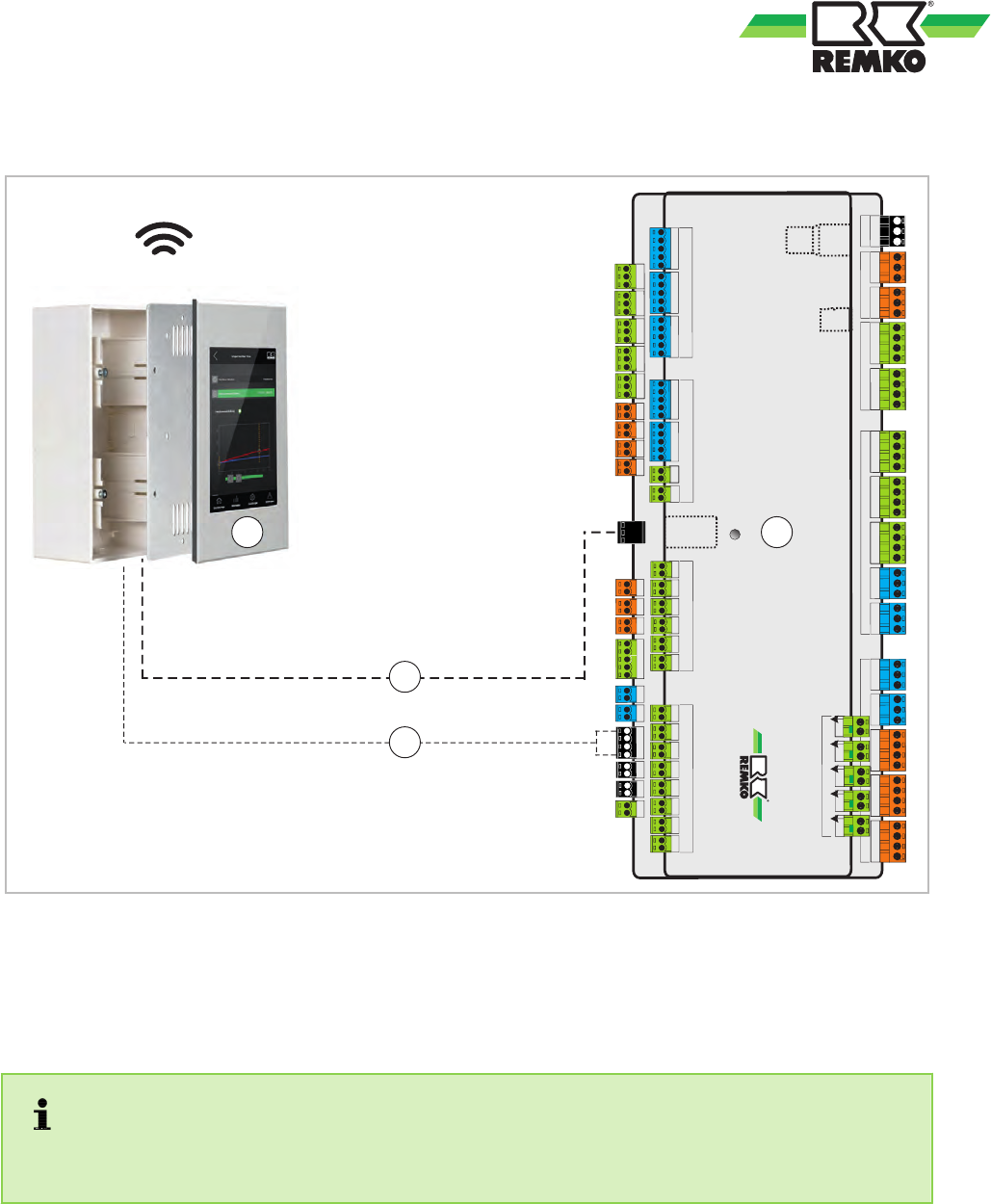
Controls, Overview ....................... 6
D
Disposal of equipment .....................6
E
Emergency-heat operation ................ 47
Enabling the flow sensor in Smart-Control .... 94
Environmental protection ...................6
Expert - setting
Acquisition of the stored energy via the S
09 probe ............................92
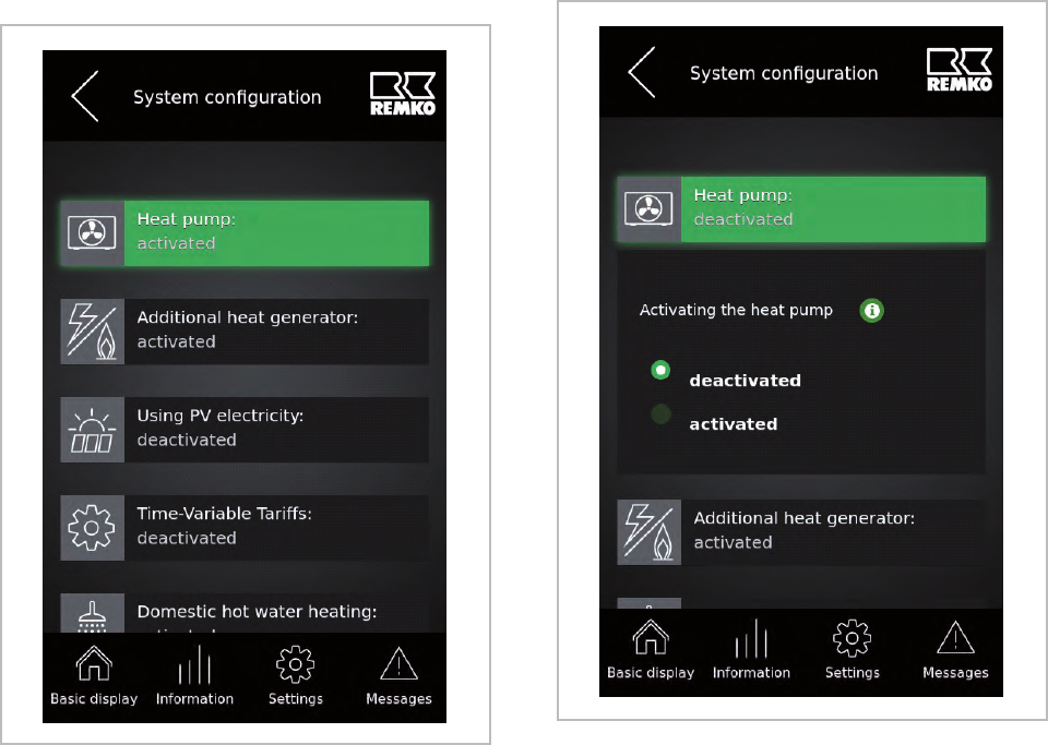
Activating the heat pump ............... 84
Asynchronous speed controller .......... 90
Building time constant ................. 88
Circulation running time ................ 86
Circulation set temperature ............. 86
Circulation type ...................... 86
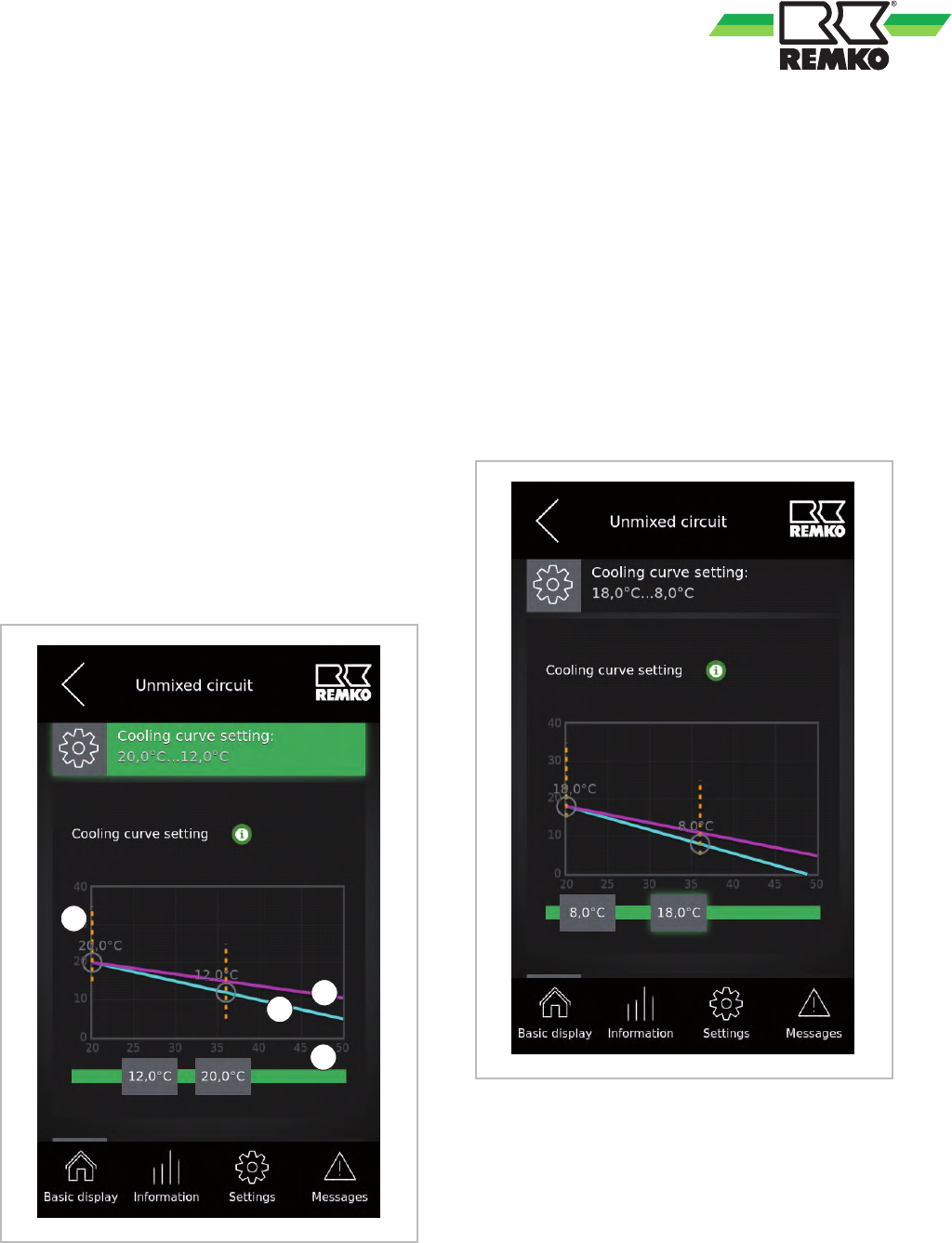
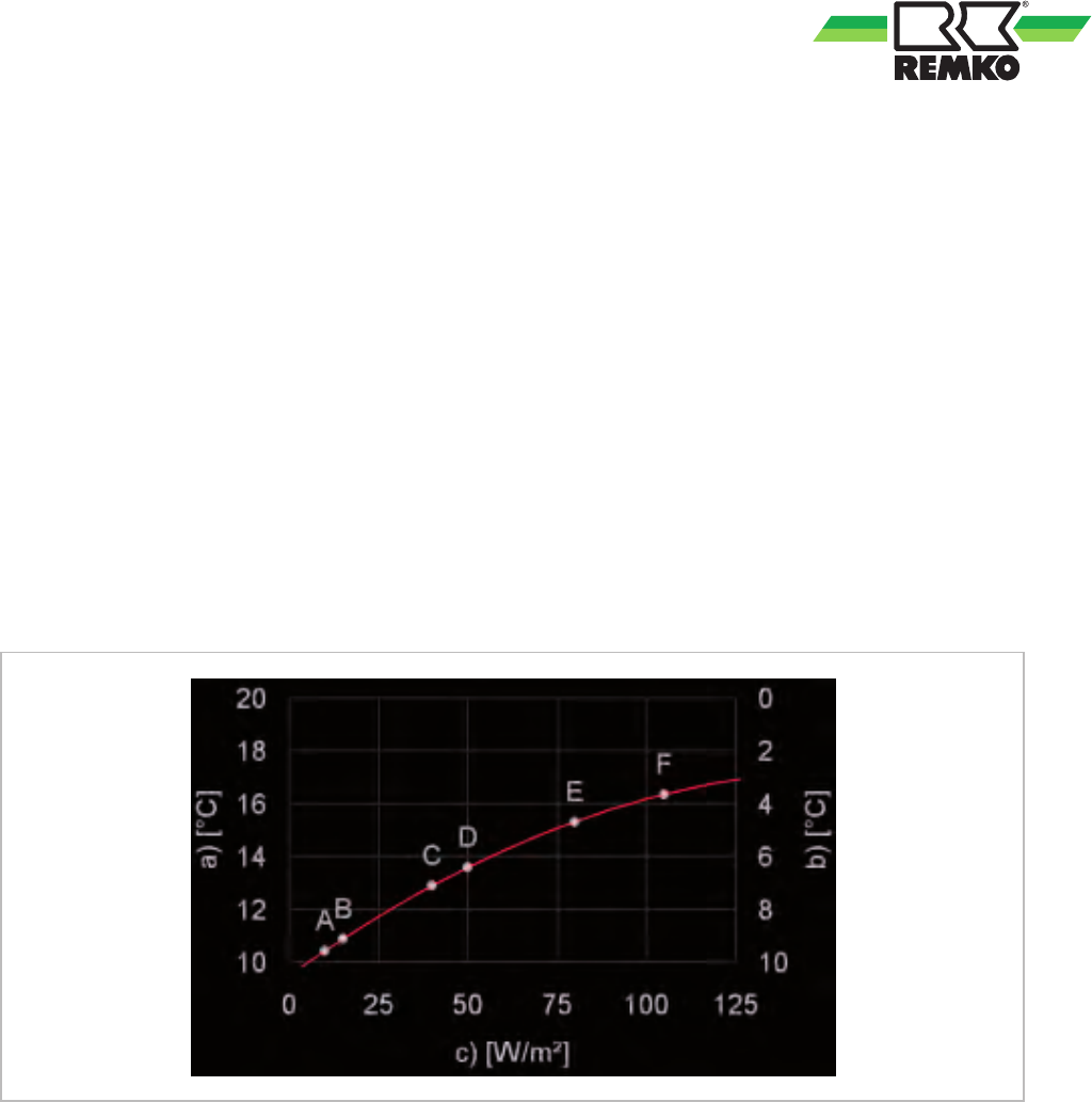
Cooling curves ....................... 31
Country ............................ 82
Country-specific settings ............... 82
Date ............................... 83
Disable switch-on .....................87
Domestic hot-water heating ............. 85
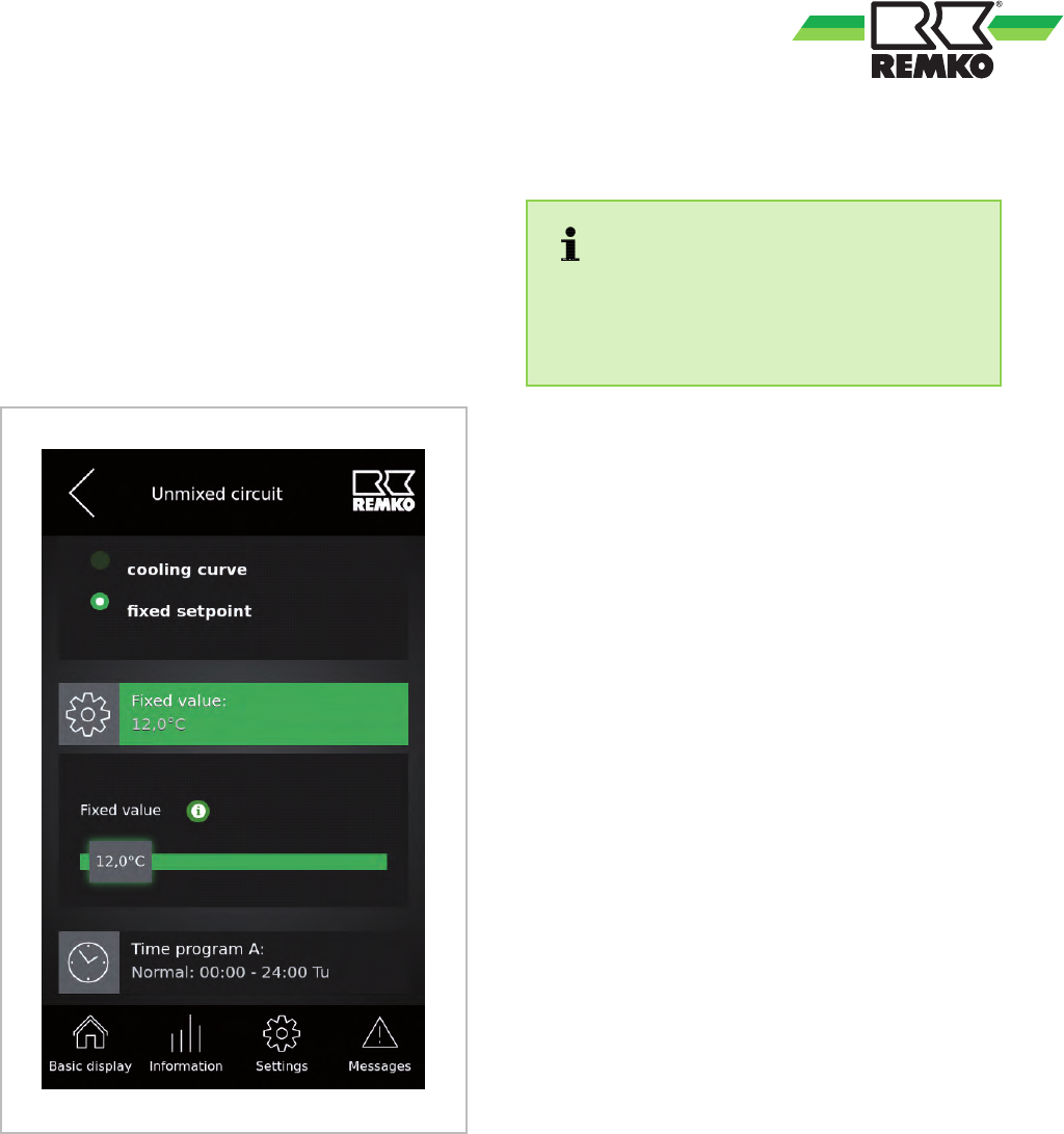
Fixed value control cooling cycle mode .... 33
Fixed-value-control heating cycle mode .... 30
Heat carrier medium ...................92
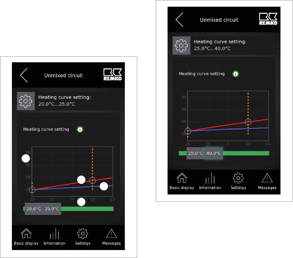
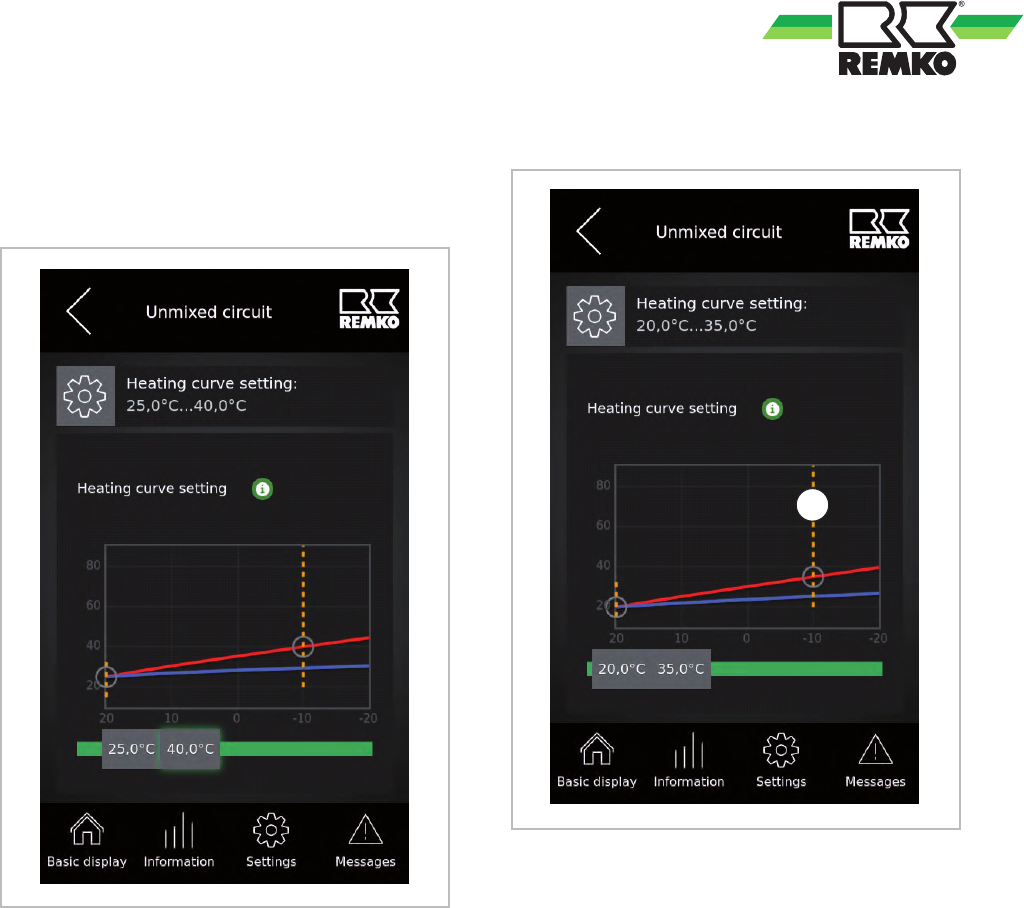
Heating curves ....................... 28
Hot water circulation ...................85
Impulse rate of the solar medium flow rate
probe .............................. 91
Impulse-guided circulation .............. 86
Language ...........................83
Load user settings .................... 84
Manual medium flow rate ............... 91
Medium flow rate probe ................ 90
Operating mode ................... 85, 87
Pump system ........................ 89
Restore counter readings ...............84
Set temperature of the storage tank during
solar charging ....................... 91
Setpoint increase ..................... 88
Solar heat meter ......................90
Solar plant .......................... 89
Solar speed control system ............. 90
Standard heating load ................. 89
Storage tank set temperature ............85
System separation underfloor heating ..... 88
T
emperature-guided circulation .......... 86
Time ...............................84
Time zone for the winter time ............ 83
Unmixed cooling cycle ................. 30
Unmixed heating cycle ................. 87
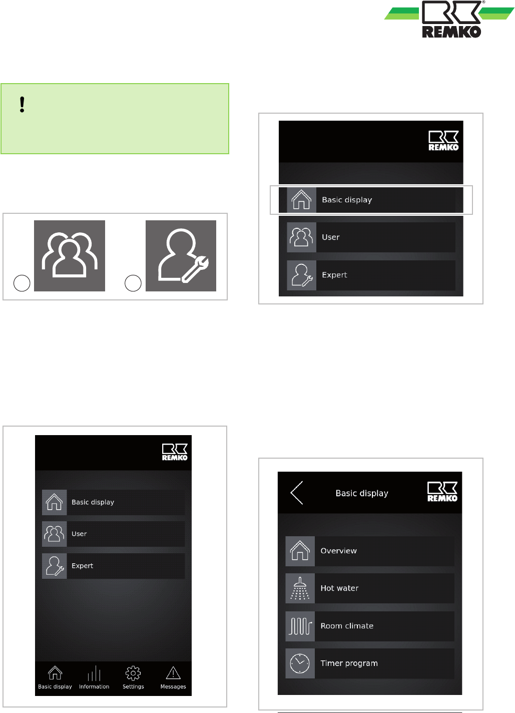
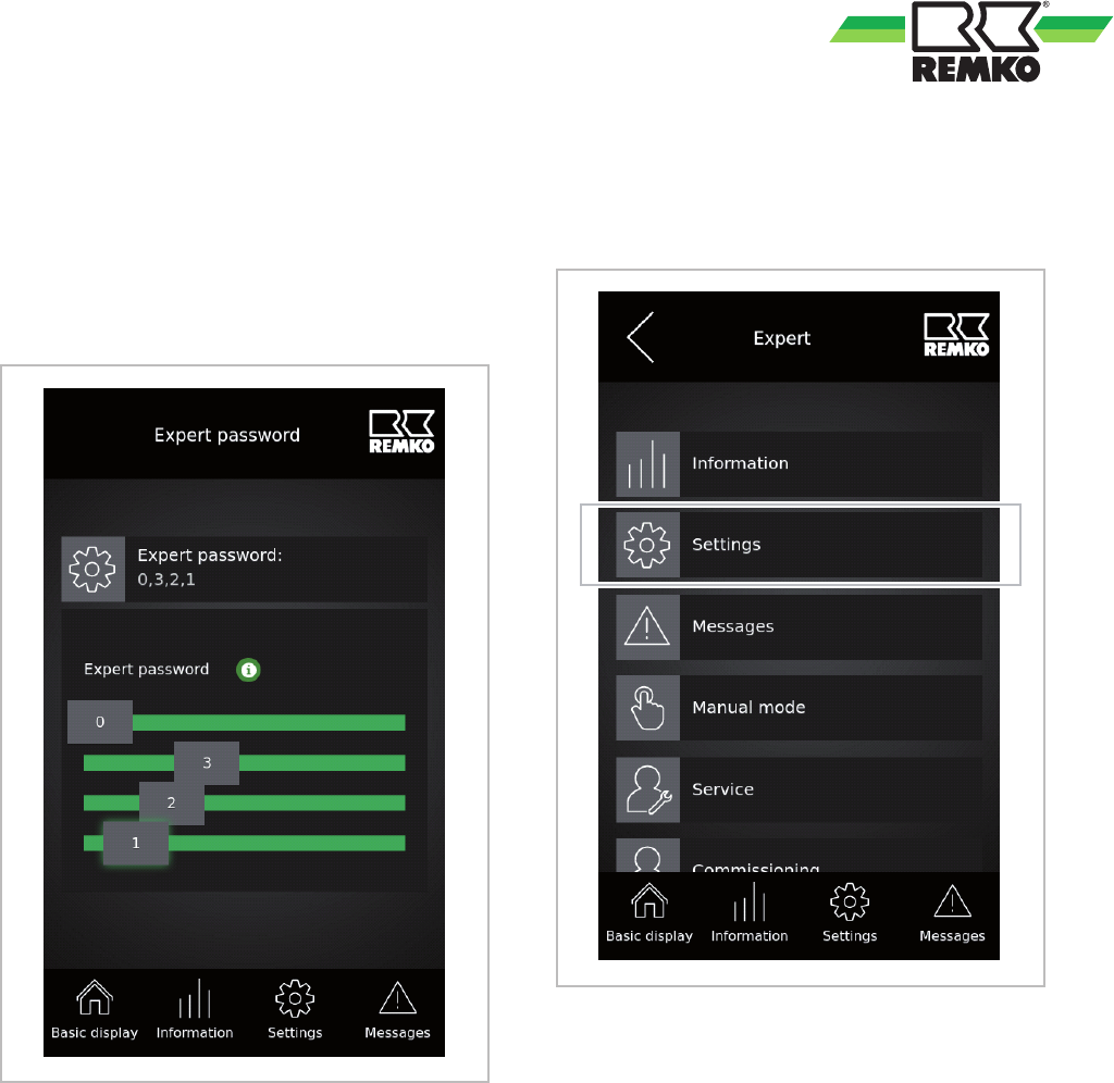
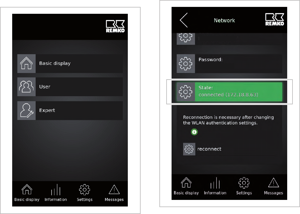
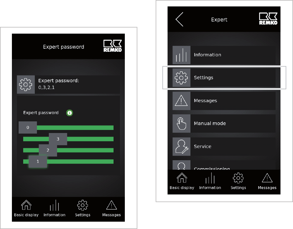
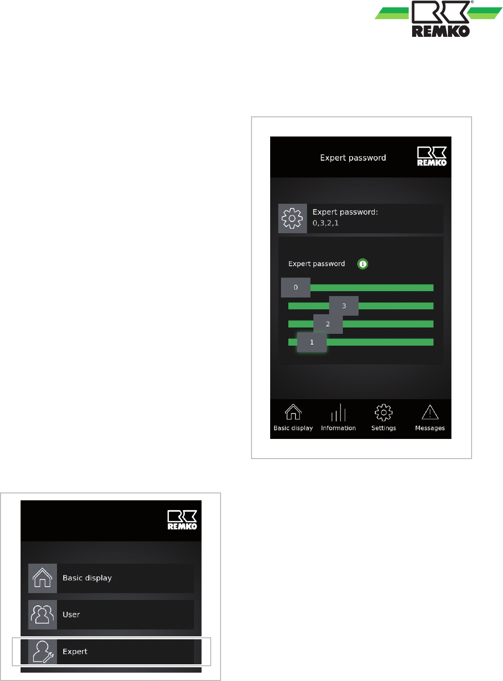
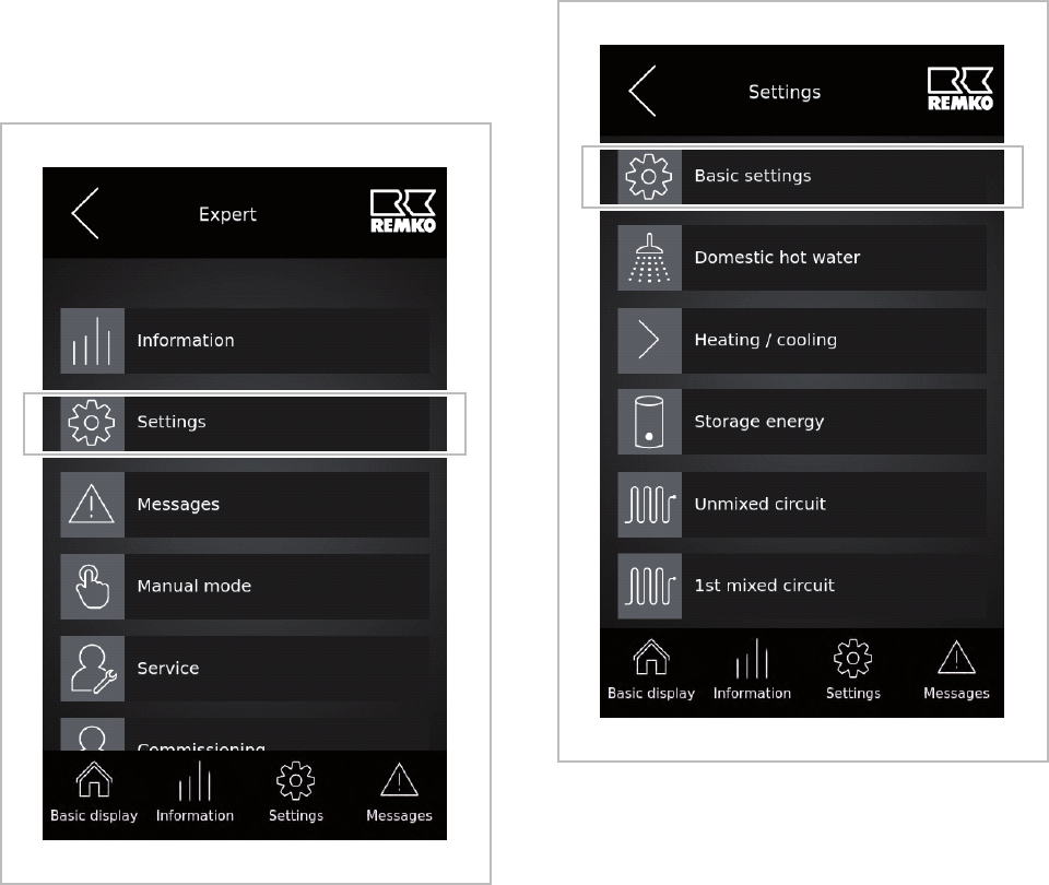
Expert mode, Selecting .................... 7
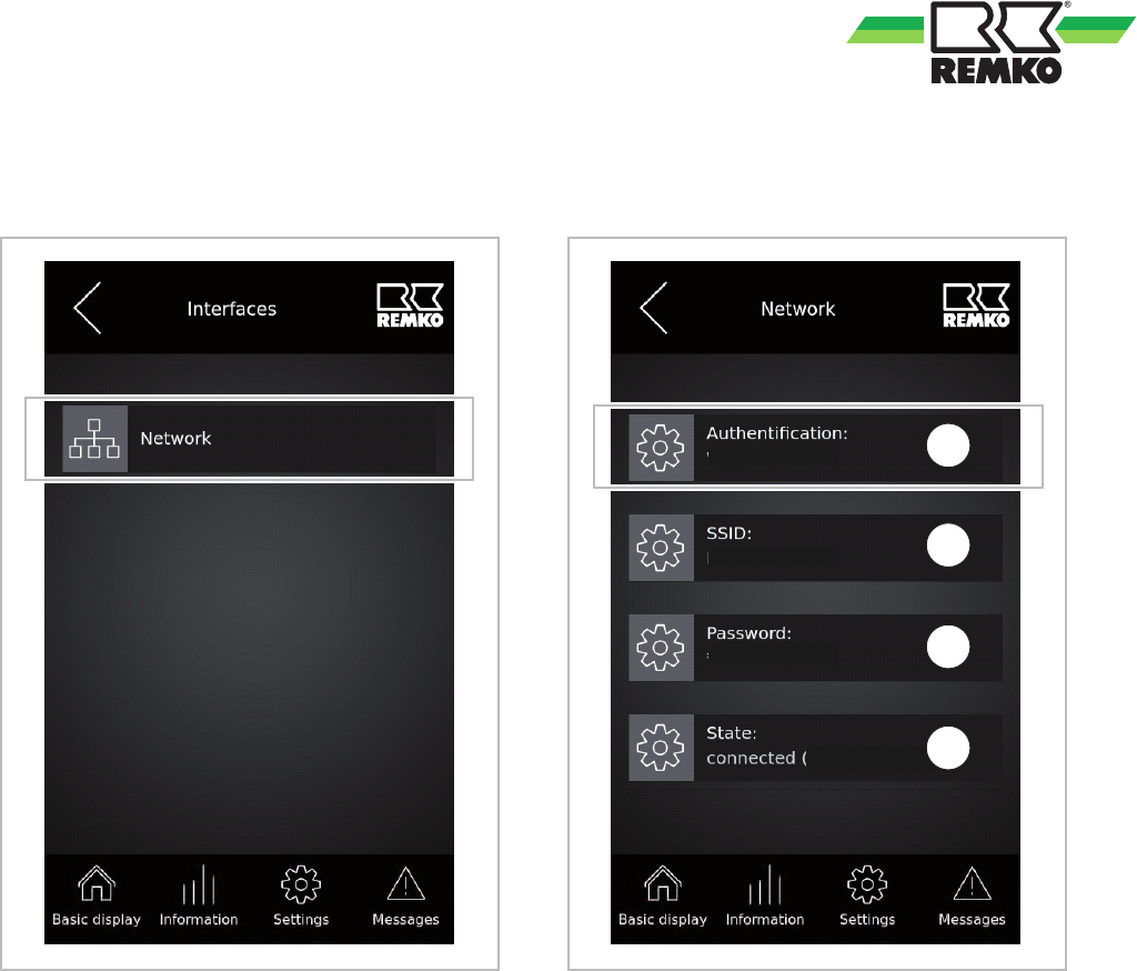
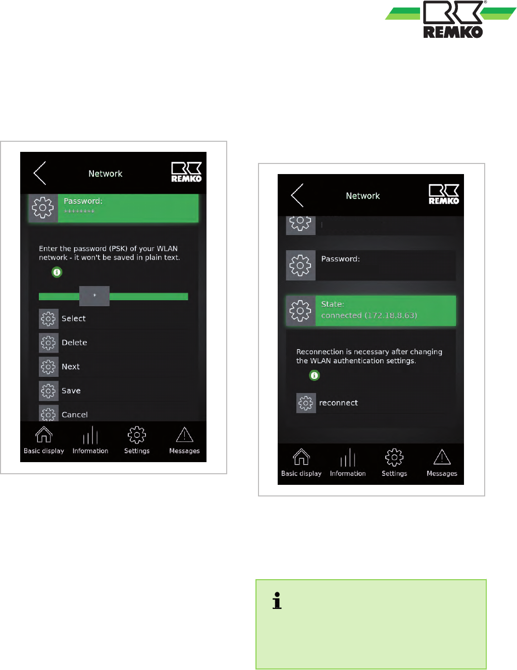
External access .........................39
F
Flow probe
Activating in Smart-Control ..............93
Enabling in Smart-Control .............. 94
Programming in Smart-Control ...........94
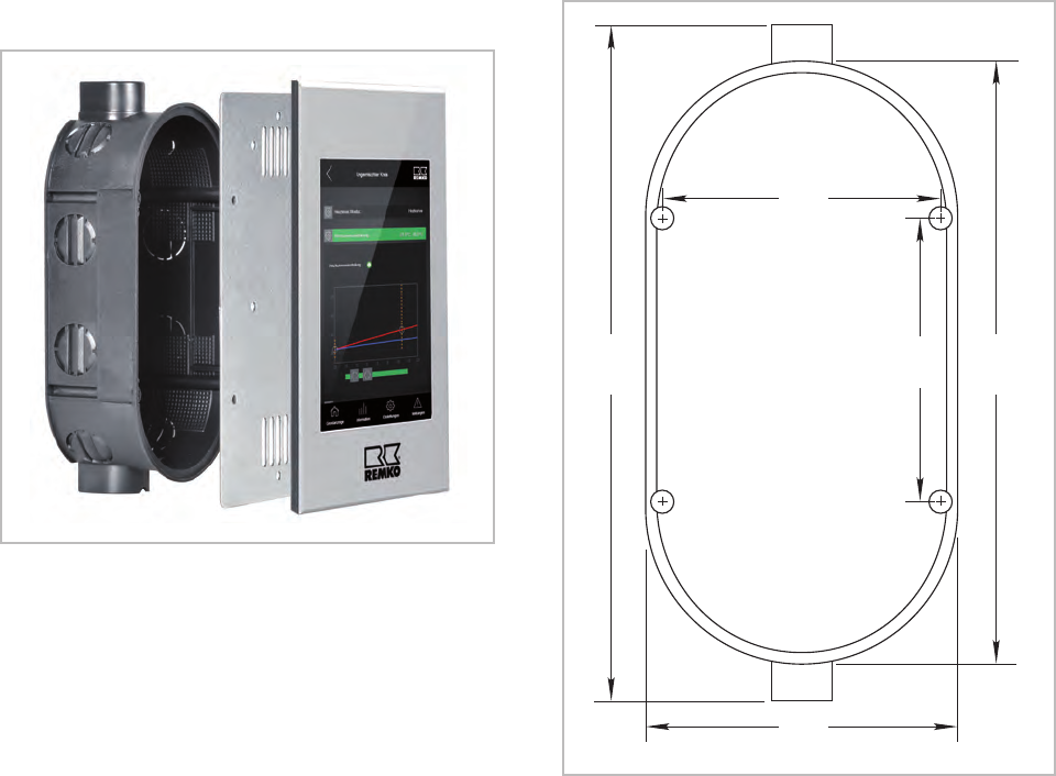
Flush-mounted installation ................114
Function display ......................... 6
H
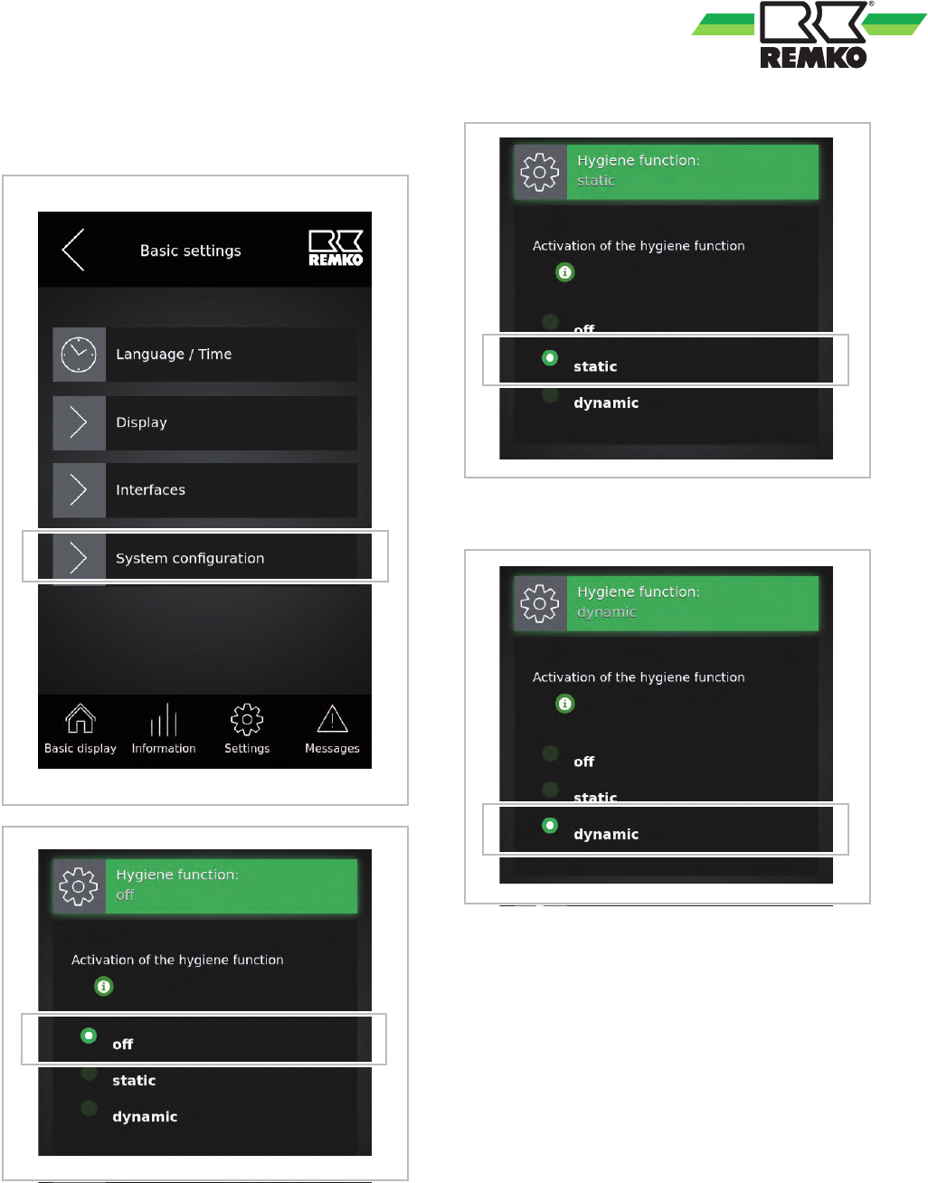
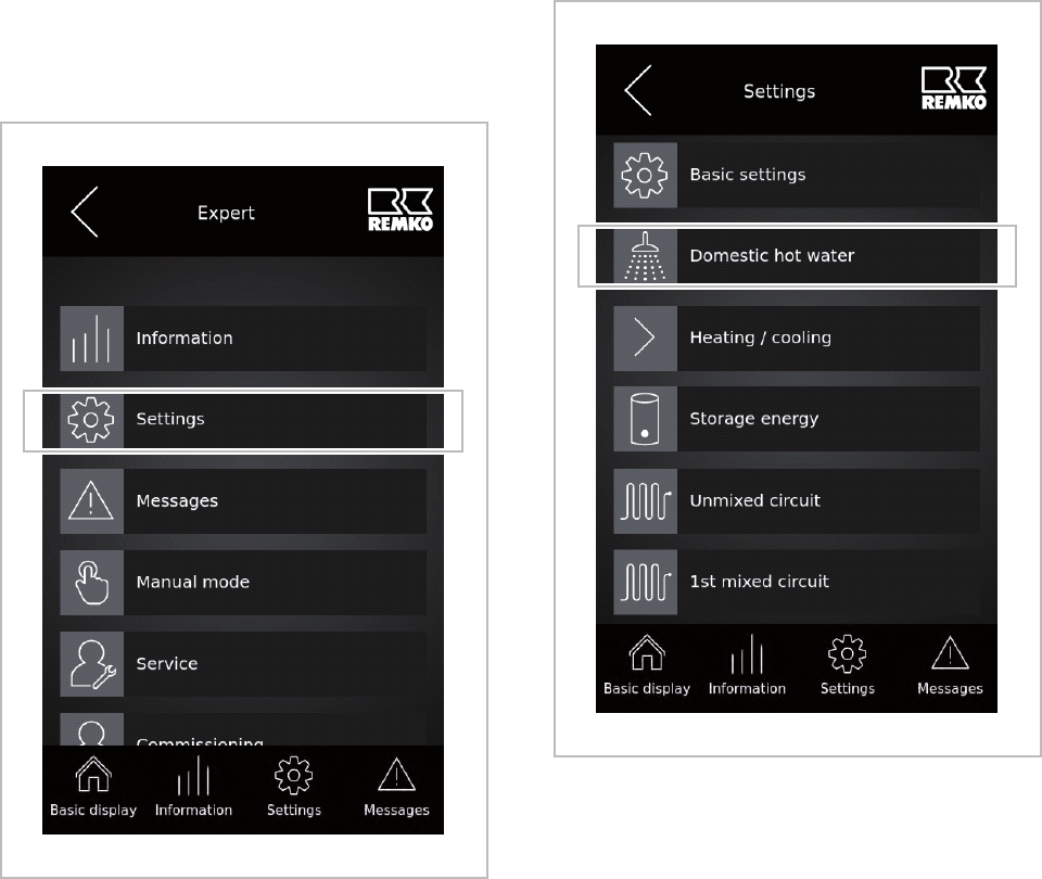
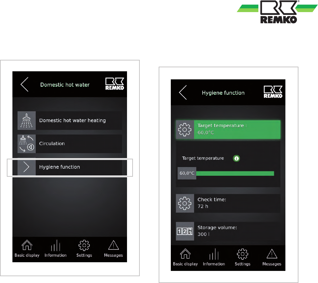
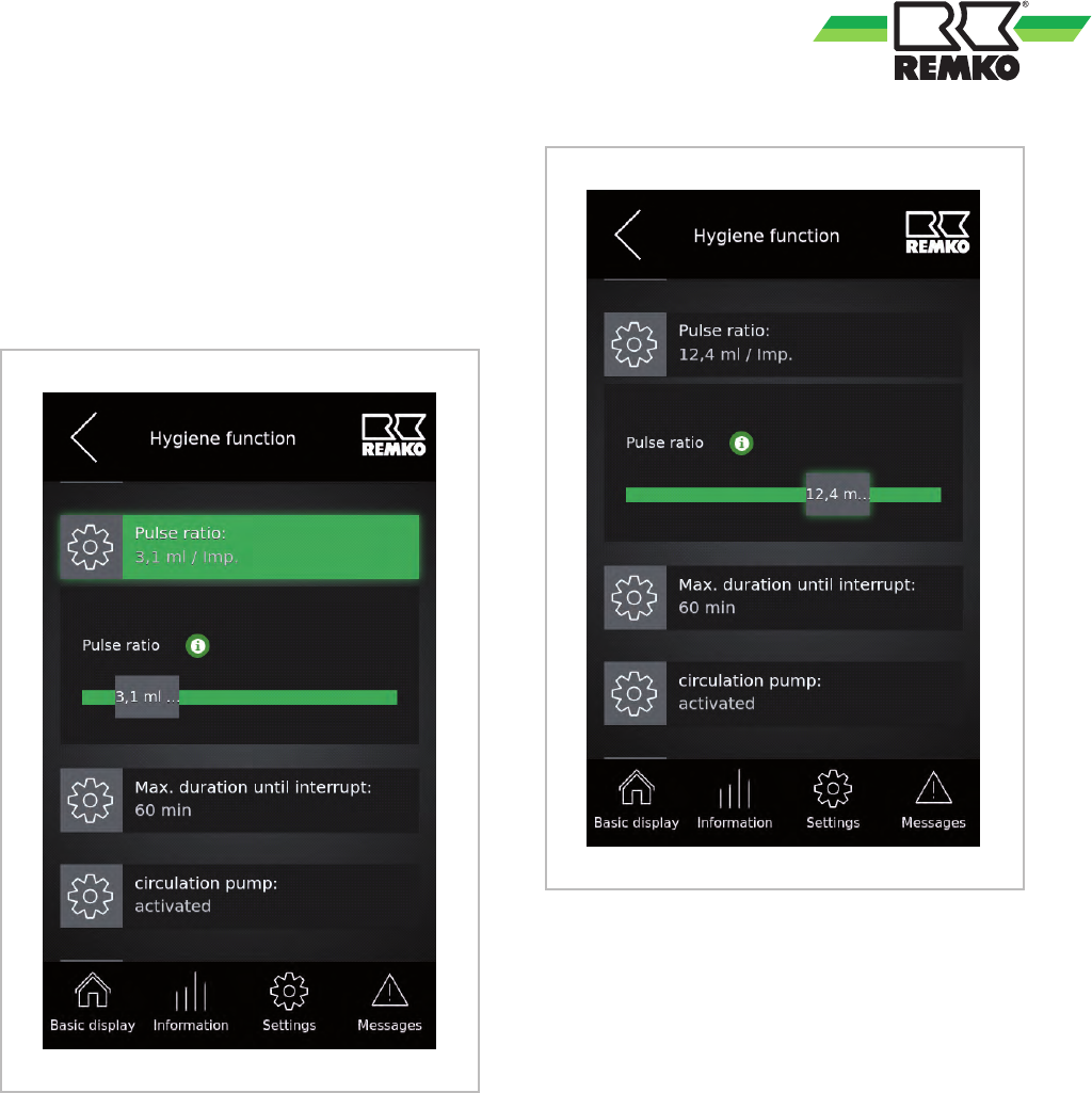
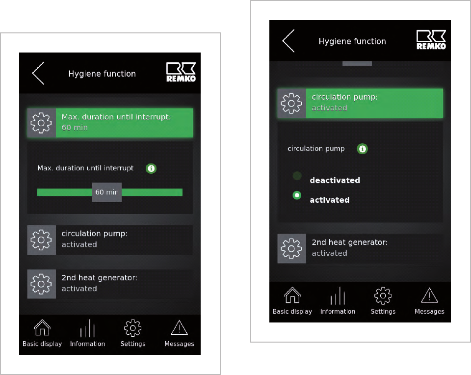
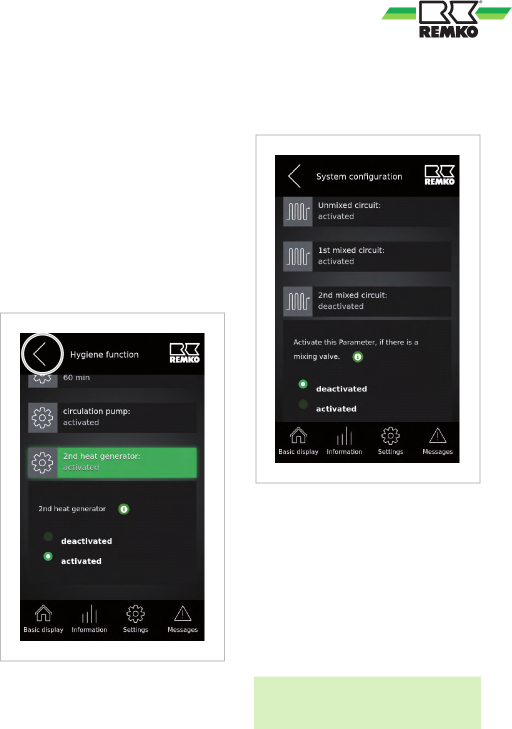
Hygiene function ........................ 93
I
Installation flush-mounted ................ 114
Installation surface-mounted .............. 113
Intended use ............................ 5
L
Legionella function ...................... 93
M
Menu
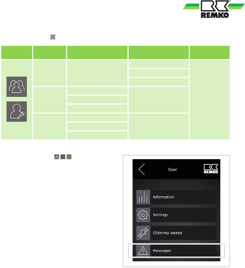
Chimney sweep ...................... 76
Information 19, 20, 21, 22, 23, 53, 54, 55,
56, 57, 58, 59, 60, 61, 62
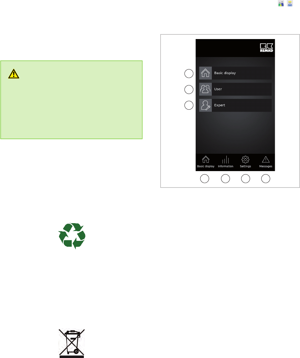
Main menu .......................... 18
Messages ...............27, 77, 78, 79, 81
Settings 24, 25, 26, 27, 63, 64, 65, 66, 67,
69, 70, 71, 72, 73, 74, 75
N
Navigation ..............................7
O
Operation
Expert level ......................... 82
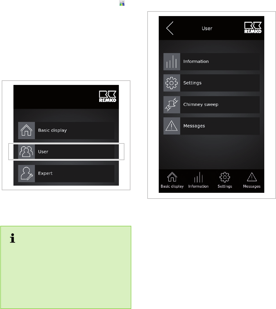
User level ........................ 14, 51
P
Programming the flow sensor in Smart-Control 94
R
Room installation ................... 113, 114
S
Safety
Dangers of failure to observe the safety
notes ............................... 4
General ............................. 4
Identification of notes ................... 4
REMKO Smart-Control Touch
118