This device has left the factory in perfect condition. To maintain this condition and to ensure a risk-free operation the user must observe the
safety instructions and warnings contained in this operation manual.
For reasons of safety and certication (CE) the unauthorised conversion and/or modication of the device is prohibited. Please note that in the
event of damage caused by the manual modication to this device any warranty claims are excluded.
The inside of the device does not contain any parts which require maintenance, with the exception of wear parts that can be exchanged from the
outside. Only qualied staff must carry out maintenance, otherwise warranty does not apply!
The fuse must exclusively be exchanged against fuses of the same class, with the same trigger features and nominal current rating.
Make sure that the power will only be supplied after the device has been fully set up. Always plug in the mains plug last. Ensure that the mains
switch is in the “OFF” position when connecting the device to power.
Only use cables that comply with regulations. Make sure that all jacks and bushes are tightened and correctly hooked up. Refer to your dealer if
you have any questions.
Ensure that when setting up the product the mains cable is not squashed or damaged by sharp edges.
Prevent the mains cable from coming into contact with other cables! Exercise great care when handling mains cables and connections. Never
touch these parts with wet hands!
Connect the power cable exclusively to appropriate shock-proof outlets. The only supply point to be used is a supply outlet in accordance with
specications of the public supply network.
Disconnect the device from the supply outlet when not in use and before cleaning! Be sure to hold the mains plug by the body. Never pull the
mains cord!
Position the device on a horizontal and stable low-ame base.
Avoid any concussions or violent impact when installing or operating the device.
When selecting the location of installation make sure that the device is not exposed to excessive heat, humidity, and dust. Be sure that no cables
lie around openly. You will endanger your own safety and that of others!
Do not rest any containers lled with liquid that could easily spill onto the device or in its immediate vicinity. If, however, uids should access the
inside of the device, immediately disconnect the mains plug. Have the device checked by a qualied service technician before re-use. Damage
caused by uids inside the device is excluded from the warranty.
Do not operate the device under extremely hot (in excess of 35° C) or extremely cold (below 5° C) conditions. Keep the device away from direct
exposure to the sun and heat sources such as radiators, ovens, etc. (even during transport in a closed vehicle). Never cover the cooling fan or
vents. Always ensure sufcient ventilation.
The device must not be operated after being taken from a cold environment into a warm environment. The condensation caused hereby may
destroy your device. Do not switch on or operate the device until it has reached ambient temperature!
Controls and switches should never be treated with spray-on cleaning agents and lubricants. This device should only be cleaned with a damp
cloth. Never use solvents or cleaning uids with a petroleum base for cleaning.
When relocating, the device should be transported in its original packaging.
Devices supplied by voltage should not be left in the hands of children. Please exercise particular care when in the presence of children.
At commercial facilities the regulations for the prevention of accidents as stipulated by the organization of professional associations must be
observed.
At schools, training facilities, hobby and self-help workshops the operation of the device must be monitored with responsibility by trained staff.
Keep this operation manual in a safe place for later reference in the event of questions or problems.
This device is a professional DJ MIDI controller with integrated 4-channel soundcard that can control software. The device should be connected
via USB cable to a computer.
This product is authorised for connection to 100 - 240 V, 60/50 Hz AC via an optional mains adapter (sold separately) and is designed exclusi-
vely for indoor application.
If the device is used for any other purposes than those described in the operation manual, damage can be caused to the product, leading to ex-
clusion of warranty rights. Moreover, any other application that does not comply with the speci ed purpose harbours risks such as short circuit,
re, electrical shock, etc.
The serial number determined by the manufacturer must never be removed to uphold the warranty rights.
20
Check the technical safety of the device regularly for damage to the mains cord or the casing, as well as for wearout of wear parts such as
rotary knobs and sliding faders.
If it is to be assumed that a safe operation is no longer feasible, then the device must be disconnected and secured against accidental use.
Always disconnect the mains plug from the outlet!
It must be assumed that a safe operation is no longer feasible, if the device bears visible defects, if the device no longer functions, following
longer storage under unfavourable conditions or after major transport stress.
21
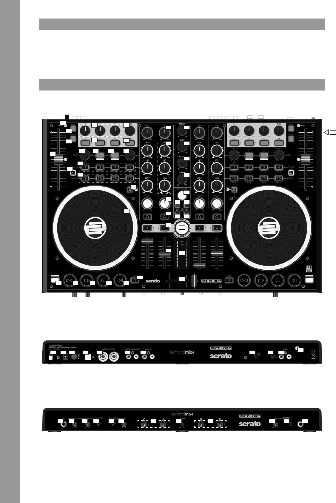
T1Pitch Fader
T2Offset LED
T3Range
T4Keylock
T5Effect Parameter
T6FX On ButtonsEffect Change Button
T7FX Tempo
T8Tap Button
T9Loop Length
T10Adjust Loop BeginningLoop-In Button
T11Adjust Loop EndingLoop-Out Button
T12Adjust Loop
T13Hot Cue ButtonsDelete Hot Cue
T14Slice Button
T15Sample Bank
T16Jog Wheel Mode Buttons
T17Jog Wheel
T18Shift Button
T19Sync Button
T20Cup Button
T21Cue Button
T22Play/Pause Button
T23Deck Select Switch
T24Gain Dial
T25EQ Dial
T26Filter Dial
T27Monitor CUE Button
T28Load ButtonFader Start Button
T29Linefader
T30Master Volume
T31Booth Volume
T32Headphones Volume
T33CUE-Mix Fading
T34Sampler Volume Dial
T35Crates Button
T36View Button
T37Back Button
T38Preparation Button
T39Track NavigationFolder Navigation
T40VU Meter
T41Crossfader
B42Mains Cord Stress Release
B43Mains Connection (DC 6V/1,5A)
B44On/Off Button
B45USB Port
B466.3 mm Master Balanced Output
B47RCA Master Unbalanced Output
B48RCA Booth Unbalanced Output
B49Shift Lock Switch
B50Line/Phono Switch
B51RCA Input 1
B52Grounding Screw
F536.3 mm Jack Microphone Connection
F54Microphone Volume
F55Microphone Equalizer
F56Microphone Routing Switch
F57Input 1 Routing Switch
F58Input 1 Volume
F59Crossfader Deck Assignment Switch
F60Crossfader Curve
F61Headphones Equalizer
F623.5 mm Jack Headphones Connection
F636.3 mm Jack Headphones Connection
S64Kesington Lock
22
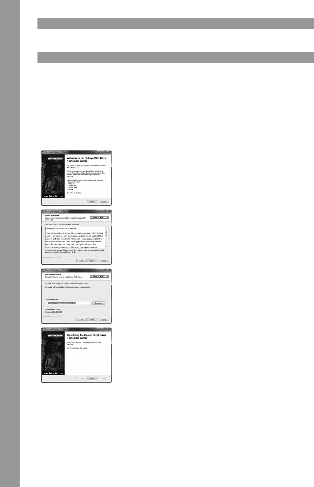
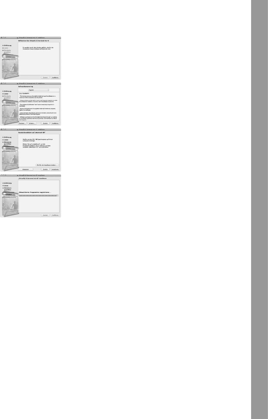
First turn off the device via the On/Off Button -B44- on the rear panel.
Then connect the included USB cable to the connection -B45- on the device‘s rear panel and a free USB port of your computer.
It is necessary to install a driver to guarantee a awless operation under Windows. Under Mac OSX a driver installation is not necessary.
Moreover, make sure that all other programs are closed. Please especially observe the following items.
Insert the included installation CD into your drive. In the folder “Drivers“ select the included ASIO driver and start the installation via a double
Cet appareil a quitté l‘usine de fabrication en parfait état. An de conserver cet état et assurer la sécurité de fonctionnement, l‘utilisateur doit
absolument respecter les consignes de sécurité et les avertissements indiqués dans ce mode d‘emploi.
Pour des raisons de sécurité et de certication (CE), il est interdit de transformer ou modier cet appareil. Tous les dégâts dus à une modica-
tion de cet appareil ne sont pas couverts par la garantie.
Le boîtier ne contient aucune pièce nécessitant un entretien, à l‘exception de pièces d‘usure pouvant être remplacées de l‘extérieur. La mainte-
nance doit exclusivement être effectuée par du personnel qualié an de conserver les droits de garantie !
Les fusibles doivent uniquement être remplacés par des fusibles de même type, dotés de caractéristiques de déclenchement et d‘un ampérage
identique.
Veillez à n‘effectuer le raccordement secteur qu‘une fois l‘installation terminée. Branchez toujours la che secteur en dernier. Vériez que
l‘interrupteur principal soit sur „OFF“ avant de brancher l‘appareil.
Utilisez uniquement des câbles conformes. Veillez à ce que toutes les ches et douilles soient bien vissées et correctement connectées. Si vous
avez des questions, contactez votre revendeur.
Veillez à ne pas coincer ou endommager le cordon d‘alimentation par des arêtes tranchantes lorsque vous installez l‘appareil.
Prenez garde à ce que le cordon électrique n‘entre pas en contact avec d‘autres câbles et soyez prudent lorsque vous manipulez des lignes ou
des prises électriques. Ne touchez jamais ces éléments avec des mains humides!
Insérez uniquement le cordon d‘alimentation dans des prises électriques de sécurité. La source de tension utilisée doit uniquement être une
prise électrique en ordre du réseau d‘alimentation publique.
Débranchez l‘appareil lorsque vous ne l‘utilisez pas ou pour le nettoyer ! Pour débrancher l‘appareil, tirez toujours sur la prise, jamais sur le câble !
Placez l‘appareil sur une surface plane, stable et difcilement inammable. En cas de larsen, éloignez les enceintes de l‘appareil.
Évitez tous les chocs et l‘emploi de la force lors de l‘installation et l‘utilisation de l‘appareil.
Installez l‘appareil dans un endroit à l‘abri de la chaleur, de l‘humidité et de la poussière. Ne laissez pas traîner les câbles pour votre sécurité
personnelle et celle de tiers!
Ne placez jamais des récipients de liquides susceptibles de se renverser sur l‘appareil ou à proximité directe. En cas d‘inltration de liquides
dans le boîtier, retirez immédiatement la che électrique. Faites contrôler l‘appareil par un technicien qualié avant de le réutiliser. La garantie
exclu tous les dégâts dus aux inltrations de liquides.
N‘utilisez pas l‘appareil dans un environnement extrêmement chaud (plus de 35°C) ou froid (sous 5° C). N‘exposez pas l‘appareil directement aux
rayons solaires ou à des sources de chaleur telles que radiateurs, fours, etc. (également valable lors du transport). Veillez à ne pas obstruer les
ventilateurs ou les fentes de ventilation. Assurez toujours une ventilation convenable.
N‘utilisez pas l‘appareil lorsqu‘il est amené d‘une pièce froide dans une pièce chaude. L‘eau de condensation peut détruire votre appareil. Laissez
l‘appareil hors tension jusqu‘à ce qu‘il ait atteint la température ambiante !
Ne nettoyez jamais les touches et curseurs avec des produits aérosols ou gras. Utilisez uniquement un chiffon légèrement humide, jamais de
solvants ou d‘essence.
Utilisez l‘emballage original pour transporter l‘appareil.
Les appareils électriques ne sont pas des jouets. Soyez particulièrement vigilants en présence d‘enfants.
Les directives de prévention des accidents de l‘association des fédérations professionnelles doivent être respectées dans les établissements
commerciaux.
Dans les écoles, instituts de formation, ateliers de loisirs etc. l‘utilisation de l‘appareil doit être effectuée sous la surveillance de personnel
qualié.
Conservez ce mode d‘emploi pour le consulter en cas de questions ou de problèmes.
Cet appareil est un contrôleur MIDI professionnel avec carte son à 4 voies permettant de commander le logiciel. L‘appareil doit pour cela être
raccordé à un ordinateur par un câble USB.
Ce produit est certié pour le branchement sur secteur 100 - 240 V, 60/50 Hz tension alternative par une che secteur optionnelle (non compri-
se dans la fourniture) et est exclusivement conçu pour être utilisé en local fermé.
Toute utilisation non conforme peut endommager le produit et annuler les droits de garantie. En outre, toute utilisation autre que celle décrite
dans ce mode d‘emploi peut être source de courts-circuits, incendies, décharge électrique, etc.
Le numéro de série attribué par le fabricant ne doit jamais être effacé sous peine d‘annuler les droits de garantie.
36
Contrôlez régulièrement le bon état de l‘appareil (boîtier, cordon) et l‘usure éventuelle des molettes et curseurs.
Si vous supposez que l‘appareil ne peut plus être utilisé en toute sécurité, mettez l‘appareil hors-service et assurez-le contre toute réutilisation
involontaire. Débranchez la che électrique de la prise de courant !
La sécurité d‘emploi est susceptible d‘être affectée lorsque l‘appareil est visiblement endommagé, ne fonctionne plus correctement, après un
stockage prolongé dans des conditions défavorable ou après une forte sollicitation de transport.
37
T1Pitch Fader
T2DEL Offset
T3Range
T4Keylock
T5Paramètre d'effet
T6Touches FX OnTouche de changement
d'effet
T7FX Tempo
T8Touche Tap
T9Longueur de boucle
T10Décalage du début d'une
boucle
Touche Loop In
T11Décalage de la n d'une
boucle
Touche Loop Out
T12Décalage de boucle
T13Touches Hot CueEffacer Hot-Cue
T14Touche Slice
T15Banc d'échantillons
T16Touche de mode Jog Wheel
T17Jog Wheel
T18Touche Maj
T19Touche de synchronisation
T20Touche Cup
T21Touche Cue
T22Touche Play/Pause
T23Sélecteur de platine
T24Régleur de gain
T25Régleur EQ
T26Régleur de ltre
T27Touche Monitor-CUE
T28Touche LoadTouche Fader Start
T29Curseur linéaire
T30Volume Master
T31Volume Booth
T32Volume du casque
T33Enchaînement CUE-Mix
T34Régleur de volume du
sampler
T35Touche Crates
T36Touche View
T37Touche Back
T38Touche Preparation
T39Navigation dans la pisteNavigation dans les
dossiers
T40VU-mètre
T41Crossfader
B42Décharge de traction du câble secteur
B43Connecteur du bloc secteur (DC 6 V/1,5 A)
B44Interrupteur marche/arrêt
B45Port USB
B46Sortie Master Balanced 6,3 mm
B47Sortie Master Unbalanced coaxiale
B48Sortie Booth Unbalanced coaxiale
B49Touche Verr. Maj
B50Commutateur Line/Phono
B51Entrée coaxiale 1
B52Vis de mise à la terre
F53Connecteur de microphone jack 6,3 mm
F54Volume du microphone
F55Égaliseur microphone
F56Sélecteur de routage du microphone
F57Sélecteur de routage Entrée 1
F58Volume Entrée 1
F59Crossfader sélecteur de platine
F60Courbe de Crossfader
F61Égaliseur casque
F62Connecteur de casque jack 3,5 mm
F63Connecteur de casque jack 6,3 mm
S64Kesington Lock
38
Commencer par éteindre l‘appareil avec l‘interrupteur marche/arrêt -B56- situé sur la face arrière.
Raccorder ensuite le câble USB fourni au port -B57- situé sur la face arrière de l‘appareil et à un port USB libre de votre ordinateur.
An d‘assurer le bon fonctionnement de l‘appareil sous Windows, l‘installation d‘un pilote est requise. Sous Mac OSX, il n‘est pas nécessaire
d‘installer un pilote. Veiller à fermer tous les autres programmes avant d‘installer le pilote. Respecter strictement les instructions ci-dessous.
Insérer le cédérom d‘installation livré dans votre lecteur. Sélectionner le pilote adapté pour votre système dans le répertoire „Drivers“ et lancer
Libble takes abuse of its services very seriously. We're committed to dealing with such abuse according to the laws in your country of residence. When you submit a report, we'll investigate it and take the appropriate action. We'll get back to you only if we require additional details or have more information to share.
Product:
Forumrules
To achieve meaningful questions, we apply the following rules:
First, read the manual;
Check if your question has been asked previously;
Try to ask your question as clearly as possible;
Did you already try to solve the problem? Please mention this;
Is your problem solved by a visitor then let him/her know in this forum;
To give a response to a question or answer, do not use this form but click on the button 'reply to this question';
Your question will be posted here and emailed to our subscribers. Therefore, avoid filling in personal details.
Register
Register getting emails for Reloop Terminal X4 at:
new questions and answers
new manuals
You will receive an email to register for one or both of the options.
Get your user manual by e-mail
Enter your email address to receive the manual of Reloop Terminal X4 in the language / languages: English, German, French, Spanish as an attachment in your email.
The manual is 0,89 mb in size.
You will receive the manual in your email within minutes. If you have not received an email, then probably have entered the wrong email address or your mailbox is too full. In addition, it may be that your ISP may have a maximum size for emails to receive.
The manual is sent by email. Check your email
If you have not received an email with the manual within fifteen minutes, it may be that you have a entered a wrong email address or that your ISP has set a maximum size to receive email that is smaller than the size of the manual.
The email address you have provided is not correct.
Please check the email address and correct it.
Your question is posted on this page
Would you like to receive an email when new answers and questions are posted? Please enter your email address.