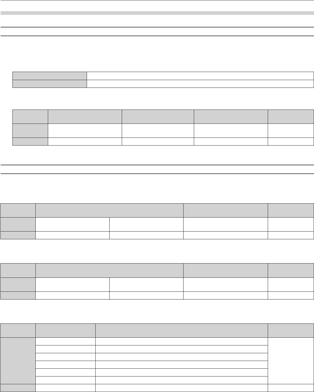
If a problem should occur inside the projector, the light source indicator <LIGHT>/temperature indicator <TEMP> will inform you by lighting or
ashing. Check the status of the indicators and manage the indicated problems as follows.
Attention
fWhen switching off the projector to deal with problems, make sure to follow the procedure in “Switching off the projector” (x page 36).
fCheck the status of the power supply with the power indicator <ON (G)/STANDBY (R)>. (x page 34)
Light source indicator <LIGHT>
Power indicator <ON (G)/STANDBY (R)>
Temperature indicator <TEMP>
Light source indicator <LIGHT>
Indicator status
Lighting in red
(projecting)
Flashing in red
(2 times)
Flashing in red
(3 times)
StatusThe light source may not light properly.The light source does not light up or has suddenly turned off.
Cause―
Solution
Turn the <MAIN POWER> switch to <OFF> (x page 36), and turn it on again.
Note
fIf the light source indicator <LIGHT> still lights or is ashing even turning the <MAIN POWER> switch to <OFF> (x page 36), ask your
dealer to repair the projector.
Temperature indicator <TEMP>
Indicator statusLighting in red
Flashing in red
(1 time)
Flashing in red
(2 times)
Flashing in red
(3 times)
StatusWarm-up status
Internal temperature is
high (warning).
Internal temperature
is high (during
projection).
Internal temperature
is high (standby
warning).
The cooling fan has
stopped.
Cause
fDid you turn on the
power when the
room temperature
was low (0 °C
(32 °F))?
fIs the air intake/exhaust port blocked?
fIs the room temperature high?
fIs [HIGH ALTITUDE MODE] set correctly?
―
Solution
fWait at least ve
minutes in the
current status.
fInstall the projector
in a location
with an ambient
temperature of 0 °C
(32 °F) to 45 °C
(113 °F)
*1
.
fRemove any objects that are blocking the air intake/exhaust port.
fInstall the projector in a location with an ambient temperature of 0 °C
(32 °F) to 45 °C (113 °F)
*1
.
fWhen using the projector at high altitudes between 1 400 m (4 593')
and 2 700 m (8 858') above sea level, set [HIGH ALTITUDE MODE]
(x page 77) to [ON].
fDo not install the projector at high altitudes of 2 700 m (8 858') or
higher above sea level.
fTurn the <MAIN
POWER>
switch to <OFF>
(x page 36), and
consult your dealer.
*1 When using the projector at high altitudes (1 400 m (4 593') – 2 700 m (8 858') above sea level), the operating environment temperature will be 0 °C
(32 °F) – 40 °C (104 °F).
Note
fIf the temperature indicator <TEMP> is still lit or ashing after taking the preceding measures, ask your dealer to repair the projector.
Chapter 5Maintenance — Maintenance
120 - ENGLISH
Maintenance
Before maintaining the projector
fMake sure to turn off the power before maintaining the projector. (x pages 34, 36)
fWhen switching off the projector, make sure to follow the procedures in “Switching off the projector” (x page 36).
Maintenance
Outer case
Wipe off dirt and dust with a soft, dry cloth.
fIf the dirt is persistent, soak the cloth with water and wring it thoroughly before wiping. Dry off the projector with a dry cloth.
fDo not use benzene, thinner, or rubbing alcohol, other solvents, or household cleaners. Doing so may deteriorate the outer case.
fWhen using chemically treated dust cloths, follow the instructions written on its packaging.
Lens front surface
Wipe off dirt and dust from the front surface of the lens with a soft clean cloth.
fDo not use a cloth that is uffy, dusty, or soaked with oil/water.
fSince the lens is fragile, do not use excessive force when wiping the lens.
Attention
fThe lens is made of glass. Impacts or excessive force when wiping may scratch its surface. Please handle with care.
Cleaning inside the projector
Ask your dealer about cleaning inside the projector every 20 000 hours of usage as an estimated duration.
fIf the projector is used in a dusty place, cleaning may be required before the usage time has reached 20 000 hours.
fIf the light source goes off or the brightness reduces noticeably, ask your dealer about replacement of the light source unit.
Chapter 5Maintenance — Troubleshooting
ENGLISH - 121
Troubleshooting
Review the following points. For details, see the corresponding pages.
ProblemsPoints to be checkedPage
Power does not turn on.
fIs the power plug rmly inserted into the outlet?―
fIs the <MAIN POWER> switch set to <OFF>?36
fIs the wall outlet supplying electricity?―
fHave the circuit breakers tripped?―
fIs the temperature indicator <TEMP> or the light source indicator <LIGHT> lit or
ashing?
119
No image appears.
fAre connections to external devices correctly performed?29
fIs the input selection setting correct?41, 85
fIs the [BRIGHTNESS] adjustment setting at a minimum?50
fIs the external device that is connected to the projector working properly?―
fIs the AV mute function in use?40
Image is fuzzy.
fIs the lens focus set correctly?37
fIs the projection distance appropriate?27
fIs the lens dirty?18
fIs the projector installed perpendicular to the screen?―
Color is pale or grayish.
fIs [COLOR] or [TINT] adjusted correctly?50
fIs the external device connected to the projector adjusted correctly?29
fIs the RGB cable damaged?―
Remote control does not
respond.
fAre the batteries depleted?―
fIs the polarity of the batteries set correctly?24
fAre there any obstructions between the remote control and the remote control
signal receiver of the projector?
22
fIs the remote control being used beyond its effective operation range?22
fAre other forms of light, such as uorescent light, affecting the projection?22
fIs the [REMOTE CONTROL] setting in [CONTROL DEVICE SETUP] set to
[DISABLE]?
97
fIs the ID number setting operation correct?24
Buttons on the control
panel do not operate.
fIs the [CONTROL PANEL] setting in [CONTROL DEVICE SETUP] set to
[DISABLE]?
97
Image does not display
correctly.
fIs the [SYSTEM SELECTOR] selection set correctly?53
fIs there a problem with the video tape or other image sources?―
fIs a signal which is not compatible with the projector being input?130
Image from a computer
does not appear.
fIs the cable too long? (Use D-Sub cables that are 10 m (32'10") or shorter.)―
fIs the external video output of the laptop computer set correctly? (Ex.: The external
output settings may be switched by pressing the “Fn” + “F3” or “Fn” + “F10”
simultaneously. Since the method varies depending on the computer type, refer to
the user manual provided with your computer.)
―
Image output from DVI-I
of the computer does not
appear.
fIs the [DVI-I IN] setting set to [EDID3]/[EDID2]?70
fThe graphics accelerator driver of the computer may need to be updated to the
latest version.
―
fThe computer may need to be restarted after performing [DVI-I IN] settings.70
fIs the [DIGITAL/ANALOG] setting in [DVI-I IN] correct?70
Video from HDMI
compatible device does
not appear or it appears
jumbled.
fIs the HDMI cable connected securely?29
fTurn the power of the projector and the external device on and off.―
fIs a signal which is not compatible with the projector being input?130
No audio is coming from
the HDMI compatible
device.
fSet audio of the external device to linear PCM.―
fCheck [AUDIO IN SELECT] of [AUDIO SETTING].89
fIf there is no audio through the HDMI cable connection, use the <AUDIO IN>
terminal.
89
There is no DIGITAL LINK
input audio or video.
fAre the connections between the twisted-pair-cable transmitter and the projector or
an external device correctly done?
―
fIs [DIGITAL LINK MODE] set to [AUTO] or [DIGITAL LINK]? Is it set to
[ETHERNET]?
98
3D function is not working.
fIs the [3D INPUT FORMAT] or [3D MODE] setting of [3D SETTINGS] correct?64
fCheck the 3D eyewear settings.―
fIs a signal which is supported by the projector being input?132
Chapter 5Maintenance — Troubleshooting
122 - ENGLISH
ProblemsPoints to be checkedPage
Left and right images are
reversed (not showing
properly).
fAre the devices synchronized? Check the 3D eyewear settings.―
fChange the [LEFT/RIGHT SWAP] setting of [3D SETTINGS].64
Image in the 3D eyewear
ickers.
fAre you within the reception range? Are there any obstructions between the 3D
eyewear and the IR transmitter? (when using VESA standard 3D eyewear)
―
3D eyewear is not
functioning.
fAre batteries of the 3D eyewear drained? If you use the rechargeable 3D eyewear,
charge it. If you use the battery-powered 3D eyewear, replace the battery.
―
fIs the IR transmitter connected properly? (when using VESA standard 3D eyewear)―
fTurn off the projector and turn it on again. (when using VESA standard 3D eyewear)―
fIs the [3D MODE] setting of [3D SETTINGS] correct?64
Attention
fIf problems persist even after checking the preceding points, consult your dealer.
ENGLISH - 123
Chapter 6 Appendix
This chapter describes specications and after-sales service for the projector.
Chapter 6Appendix — Technical information
124 - ENGLISH
Technical information
PJLink protocol
The network function of this projector supports the PJLink class 1, and the PJLink protocol can be used to perform projector setting and
projector status query operations from a computer.
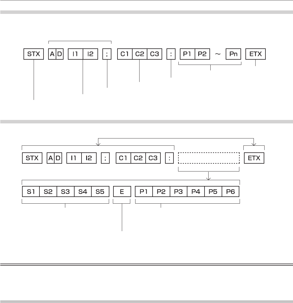
Control commands
The following table lists the PJLink protocol commands that can be used to control the projector.
fx characters in tables are non-specic characters.
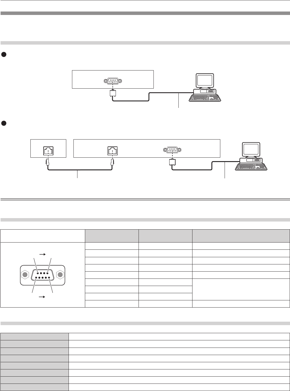
D-Sub 9 p, 1 set, RS-232C compliant, for computer control
<VARIABLE
AUDIO OUT>
terminal
1 set, M3 stereo mini jack (monitor output, with stereo support) 0 V [rms] to 1.8 V [rms] (variable), output
impedance 2.2 kΩ or lower
<AUDIO IN>
terminal
1 set, M3 stereo mini jack 0.5 V [rms], input impedance 22 kΩ or higher
<DIGITAL LINK/
LAN> terminal
1 set, for RJ-45 network, DIGITAL LINK connection, PJLink compatible, 100Base-TX
<3D SYNC>
terminal
1 set, Mini DIN 3 p, for 3D IR transmitter connection
Power cable length3.0 m (118-1/8")
Outer caseMolded plastic
Dimensions
Width: 455 mm (17-29/32")
Height: 137 mm (5-13/32") (with minimum feet length)
Depth: 415 mm (16-11/32") (including lens)
Weight
Approx. 11 k] (24.3 lbs.)
*1
Noise level
*2
When [LIGHT POWER] is set to [NORMAL]: 35 dB
When [LIGHT POWER] is set to [LOW]: 29 dB
Operating environment
Operating environment temperature
*3
: 0 °C (32 °F) to 45 °C (113 °F)
Operating environment humidity: 20 % to 80 % (no condensation)
Remote
control
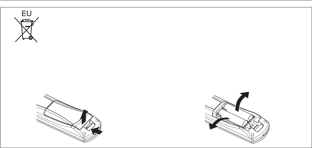
Power supplyDC 3 V (AA/R6/LR6 battery x 2)
Operating rangeWithin 15 m (49'2") (when operated directly in front of signal receiver)
Weight
117 ] (4.1 ozs.) (including batteries)
DimensionsWidth: 48 mm (1-7/8"), Height: 163 mm (6-13/32"), Depth: 24.5 mm (31/32")
*1 Average value. Weight varies for each product.
*2 Measurement, measuring conditions and method of notation all comply with ISO21118 international standards.
*3 When using the projector at high altitudes (1 400 m (4 593') – 2 700 m (8 858') above sea level), the operating environment temperature will be 0 °C
(32 °F) – 40 °C (104 °F). When the ambient temperature becomes 35 °C (95 °F) or higher, the output light may be reduced to protect the projector.
Note
fThe model numbers of accessories and optional components are subject to change without notice.
Chapter 6Appendix — Dimensions
ENGLISH - 135
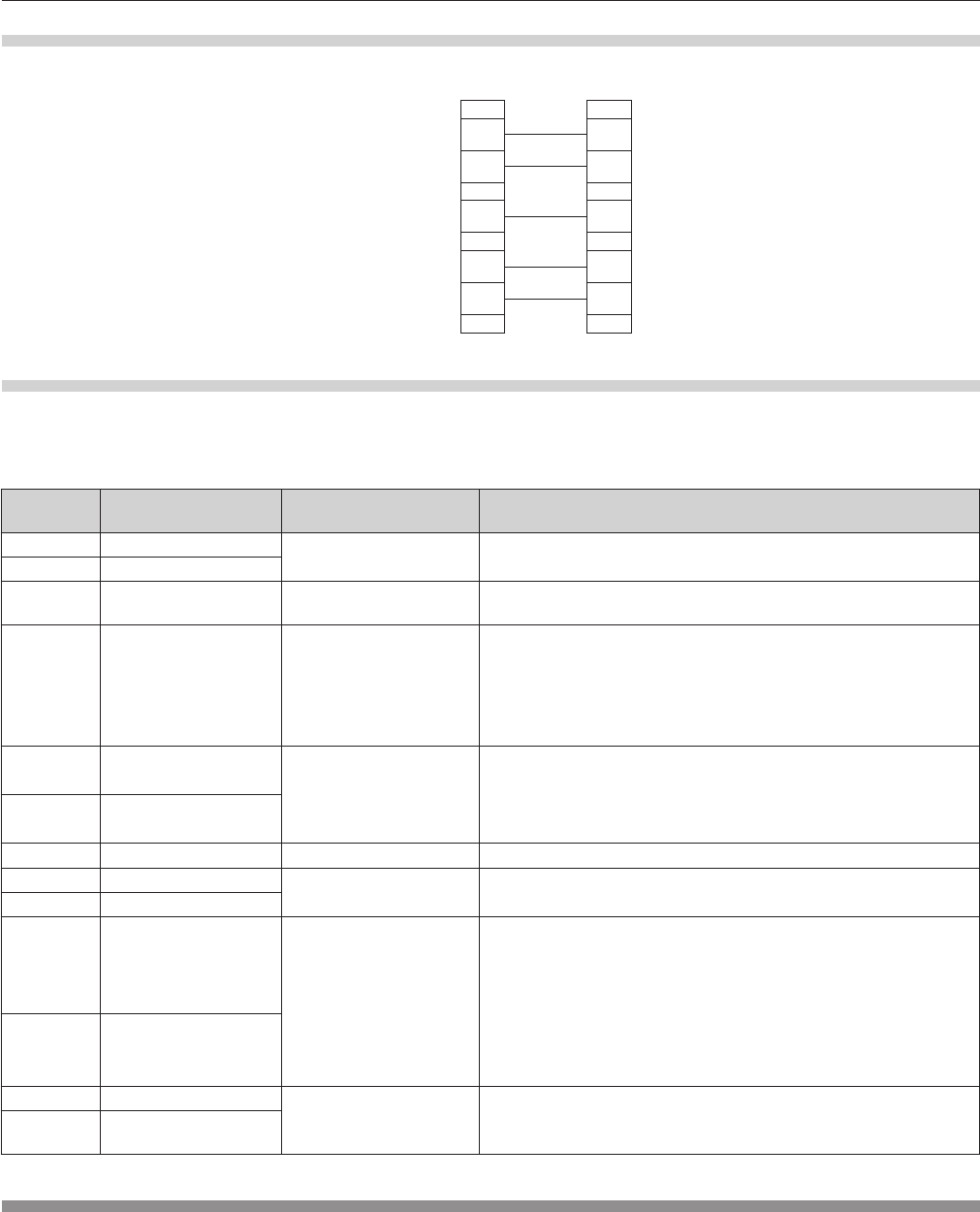
Dimensions
Unit: mm
409 (16-3/32")
415 (16-11/32")
455 (17-29/32")
63.5 (2-1/2")
72 (2-27/32")
72 (2-27/32")
63.5 (2-1/2")
137 (5-13/32")
128.5 (5-1/16")
125 (4-29/32")
* Actual dimensions may differ depending on the product.
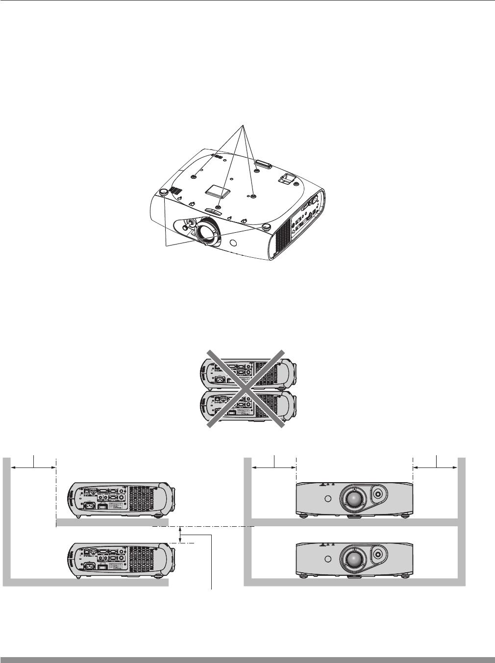
Chapter 6Appendix — Ceiling mount bracket safeguards
136 - ENGLISH
Ceiling mount bracket safeguards
fWhen installing the projector to a ceiling, be sure to use the specied ceiling mount bracket (Model No.: ET-PKR100H (for high ceilings),
Libble takes abuse of its services very seriously. We're committed to dealing with such abuse according to the laws in your country of residence. When you submit a report, we'll investigate it and take the appropriate action. We'll get back to you only if we require additional details or have more information to share.
Product:
Forumrules
To achieve meaningful questions, we apply the following rules:
First, read the manual;
Check if your question has been asked previously;
Try to ask your question as clearly as possible;
Did you already try to solve the problem? Please mention this;
Is your problem solved by a visitor then let him/her know in this forum;
To give a response to a question or answer, do not use this form but click on the button 'reply to this question';
Your question will be posted here and emailed to our subscribers. Therefore, avoid filling in personal details.
Register
Register getting emails for Panasonic PT-RZ470 at:
new questions and answers
new manuals
You will receive an email to register for one or both of the options.
Get your user manual by e-mail
Enter your email address to receive the manual of Panasonic PT-RZ470 in the language / languages: English as an attachment in your email.
The manual is 18,47 mb in size.
You will receive the manual in your email within minutes. If you have not received an email, then probably have entered the wrong email address or your mailbox is too full. In addition, it may be that your ISP may have a maximum size for emails to receive.
The manual is sent by email. Check your email
If you have not received an email with the manual within fifteen minutes, it may be that you have a entered a wrong email address or that your ISP has set a maximum size to receive email that is smaller than the size of the manual.
The email address you have provided is not correct.
Please check the email address and correct it.
Your question is posted on this page
Would you like to receive an email when new answers and questions are posted? Please enter your email address.