fRemove any objects that are blocking the air intake/
exhaust port.
fInstall the projector in a location with the operating
environment temperature between 0 °C (32 °F) and
50 °C (122 °F)
*1
, and ambient humidity between 10 %
and 80 % (no condensation).
fClean or replace the air lter unit. (x page 184)
fTurn the <MAIN POWER>
switch to <OFF>
(x page 63), and
consult your dealer.
*1 The operating environment temperature should be between 0 °C (32 °F) and 45 °C (113 °F) if the projector is used at an altitude between 1 400 m
(4 593') and 4 200 m (13 780') above sea level. When [OPERATING MODE] in the [PROJECTOR SETUP] menu → [OPERATION SETTING] is
set to [ECO], [LONG LIFE1], [LONG LIFE2], or [LONG LIFE3], the operating environment temperature should be between 0 °C (32 °F) and 45 °C
(113 °F), and when the Smoke Cut Filter is used, it should be between 0 °C (32 °F) and 40 °C (104 °F) regardless of the altitude.
When [OPERATING MODE] in the [PROJECTOR SETUP] menu → [OPERATION SETTING] is set to [ECO], [LONG LIFE1], [LONG LIFE2], or
[LONG LIFE3], the projector cannot be used at an altitude of 2 700 m (8 858') or higher above sea level. When the Smoke Cut Filter is used, the
projector cannot be used at an altitude of 1 400 m (4 593') or higher above sea level.
Note
fIf the temperature indicator <TEMP> is still lit or blinking after taking the measures, ask your dealer for repair.
Filter indicator <FILTER>
Indicator statusLighting in redBlinking in red
Status
The lter is clogged.
The temperature inside or outside the projector is abnormally high.
The air lter unit is not
attached.
CausefIs the air lter unit dirty?
fIs the air intake/exhaust
port blocked?
fIs the projector used at
an altitude of 4 200 m
(13 780')
*1
or higher
above sea level?
fIs the air lter unit
attached?
Solution
fClean or replace the air
lter unit. (x page 184)
fRemove any objects that
are blocking the air intake/
exhaust port.
fDo not use the projector
at an altitude of 4 200 m
(13 780')
*1
or higher
above sea level.
fAttach the air lter unit.
*1 When [OPERATING MODE] in the [PROJECTOR SETUP] menu → [OPERATION SETTING] is set to [ECO], [LONG LIFE1], [LONG LIFE2], or
[LONG LIFE3], the projector cannot be used at an altitude of 2 700 m (8 858') or higher above sea level. When the Smoke Cut Filter is used, the
projector cannot be used at an altitude of 1 400 m (4 593') or higher above sea level.
Note
fIf the lter indicator <FILTER> is still lit or blinking after taking the measures, ask your dealer for repair.
Chapter 5Maintenance — Maintenance/replacement
184 - ENGLISH
Maintenance/replacement
Before performing maintenance/replacement
fMake sure to turn off the power before maintaining or replacing the unit. (x pages 54, 63)
fWhen switching off the projector, make sure to follow the procedures in “Switching off the projector”
(x page 63).
Maintenance
Outer case
Wipe off dirt and dust with a soft, dry cloth.
fIf the dirt is persistent, soak the cloth with water and wring it thoroughly before wiping. Dry off the projector with
a dry cloth.
fDo not use benzene, thinner, or rubbing alcohol, other solvents, or household cleaners. Doing so may
deteriorate the outer case.
fWhen using chemically treated dust cloths, follow the instructions written on its packaging.
Lens front surface
Wipe off dirt and dust from the front surface of the lens with a soft clean cloth.
fDo not use a cloth that is uffy, dusty, or soaked with oil/water.
fSince the lens is fragile, do not use excessive force when wiping the lens.
Attention
fThe lens is made of glass. Impacts or excessive force when wiping may scratch its surface. Handle with care.
Air lter unit
Perform maintenance of the air lter unit in the following cases.
fThe air lter is clogged with dust, causing the lter replacement message to appear on the screen and the lter
indicator <FILTER> to light in red.
Attention
fMake sure to turn off the power before performing maintenance on the air lter unit.
fMake sure that the projector is stable, and perform the maintenance in a safe place even if you drop it accidentally.
Removing the air lter unit
Air filter cover fixing screw
Air filter cover
Fig. 1
Tabs on the
projector body
Tabs on the projector
body
Air filter unit
Air filter unit compartment and the
projector’s air intake port
Fig. 2Fig. 3
1) Remove the air filter cover. (Fig. 1)
fUse a Phillips screwdriver to turn the air lter cover screw counterclockwise until it turns freely, and then
remove the air lter cover.
fLoosen the air lter cover xing screw while putting your hand on.
2) Pull out the air filter unit.
fPull out the air lter unit frame from the tabs of the projector body while slightly pressing around the center
of the frame at the front side (with the lens) inward as described with the arrow, and pull out the frame at the
opposite side from the tabs to remove the air lter unit. (Fig. 2)
Chapter 5Maintenance — Maintenance/replacement
ENGLISH - 185
fAfter pulling out the air lter unit, remove large foreign objects and dust from the air lter unit compartment
and the air intake port of the projector body if there are any. (Fig. 3)
Cleaning the air lter unit
Remove the air lter unit beforehand with the previously described procedure of “Removing the air lter unit”.
Fig. 1Fig. 2
1) Wash the air filter unit. (Fig. 1)
i) Soak the air filter unit in cold or warm water and then lightly rinse it.
fDo not use cleaning tools such as brushes.
fWhen rinsing, hold the frame of the air lter unit without putting strong pressure on the lter unit.
ii) Rinse the air filter unit two to three times using fresh water each time.
fInsufcient rinsing may result in odors.
2) Dry the air filter unit. (Fig. 2)
fLet the air lter unit naturally dry off in a well-ventilated place where there is little dust and is not exposed to
direct sunlight.
fDo not dry using drying devices such as dryers.
fAfter the air lter is dried, proceed to “Attaching the air lter unit” (x page 185).
Attaching the air lter unit
Protrusion of the air filter unit
Tabs on the projector body
Tabs on the projector body
Groove on the projector body
Protrusion of the air filter unit
Groove on the projector body
1) Attach the air filter unit to the projector.
fThe air lter unit has no difference between top and bottom, but is two-sided. Match the protrusion position
of the air lter unit with the grooves on the projector body.
fHook the air lter unit frame at the air exhaust port side to the two tabs of the back side of the projector’s air
lter unit compartment and perform Step 2) in “Removing the air lter unit” in the reverse order to attach.
fConrm that the tabs of the air lter unit compartment of the projector body are hooked to the air lter unit
frame.
2) Attach the air filter cover to the projector and use a Phillips screwdriver to tighten the air filter cover
screw.
fAttach the air lter cover by performing Step 1) in “Removing the air lter unit” (x page 184) in the reverse
order.
Attention
fAfter washing the air lter unit, dry it thoroughly before attaching it back to the projector. Attaching a wet unit will cause an electric shock or
malfunction.
fDo not disassemble the air lter unit.
fTake care not to touch the air intake fan in the air lter unit compartment when removing dirt or dust.
Chapter 5Maintenance — Maintenance/replacement
186 - ENGLISH
Note
fMake sure that the air lter unit is properly attached before using the projector. If it is not properly attached, the projector will suck in dirt and
dust causing a malfunction.
fIf you use the projector without attaching the air lter unit, the lter indicator <FILTER> blinks in red and the message appears on the
projected image for approximately 30 seconds.
fReplace the air lter unit with the new optional Replacement Filter Unit (Model No.: ET-EMF330) if it is damaged or if the dirt does not come
off even after washing.
fAir lter replacement is recommended after cleaning the unit two times.
fThe dust-proof properties may be reduced after each cleaning.
Replacing the unit
Air lter unit
If dirt does not come off even after the unit is maintained, it is time for the unit to be replaced.
The Replacement Filter Unit (Model No.: ET-EMF330) is an optional accessory. To purchase the product, consult
your dealer.
Replacing the air lter unit
Attention
fMake sure to turn off the power before replacing the air lter unit.
fWhen attaching the unit, make sure that the projector is stable, and perform the replacement in a safe place even if you drop it accidentally.
1) Remove the air filter unit.
fRefer to “Removing the air lter unit” (x page 184).
2) Attach the optional Replacement Filter Unit (Model No.: ET-EMF330) to the projector.
fThe air lter unit has no difference between top and bottom, but is two-sided. Match the protrusion position
of the air lter unit with the grooves on the projector body.
fRefer to “Attaching the air lter unit” (x page 185).
Attention
fWhen switching on the projector, make sure that the air lter unit is attached. If it is not properly attached, the projector will suck in dirt and
dust causing a malfunction.
fIf you use the projector without attaching the air lter unit, the lter indicator <FILTER> blinks in red and the message appears on the
projected image for approximately 30 seconds.
Note
fThe replacement cycle of the air lter unit varies greatly depending on the usage environment.
Chapter 5Maintenance — Troubleshooting
ENGLISH - 187
Troubleshooting
Review the following points. For details, see the corresponding pages.
ProblemsPoints to be checkedPage
Power does not turn on.
fIs the power plug rmly inserted into the outlet?―
fIs the <MAIN POWER> switch set to <OFF>?63
fIs the wall outlet supplying electricity?―
fHave the circuit breakers tripped?―
fAre the light source indicators <LIGHT1>/<LIGHT2> or the temperature indicator
<TEMP> lighting or blinking?
182
No image appears.
fAre connections to external devices correctly performed?48
fIs the input selection setting correct?70
fIs the [BRIGHTNESS] adjustment setting at a minimum?83
fIs the external device that is connected to the projector working properly?―
fIs the shutter function in use?71
fIf the power indicator <ON (G)/STANDBY (R)> is blinking in red, consult your dealer.―
fIs the lens cover still attached to the lens?55
Image is fuzzy.
fIs the lens focus set correctly?64
fIs the projection distance appropriate?35
fIs the lens dirty?22
fIs the projector installed perpendicular to the screen?―
Color is pale or grayish.
fAre [COLOR] and [TINT] adjusted correctly?83
fIs the external device connected to the projector adjusted correctly?48
fIs the RGB cable damaged?―
Remote control does not
respond.
fAre the batteries depleted?―
fIs the polarity of the batteries set correctly?31
fAre there any obstructions between the remote control and the remote control
signal receiver of the projector?
26
fIs the remote control being used beyond its effective operation range?27
fAre other forms of light, such as uorescent light, affecting the projection?27
fIs the [REMOTE CONTROL] setting in [CONTROL DEVICE SETUP] set to
[DISABLE]?
153
fIs the <REMOTE 2 IN> terminal used for contact control?203
fIs the ID number setting operation correct?74
Menu screen does not
appear.
fIs the on-screen display function turned off (hidden)?118
Buttons on the control
panel do not operate.
fIs the [CONTROL PANEL] setting in [CONTROL DEVICE SETUP] set to
[DISABLE]?
153
fIs the <REMOTE 2 IN> terminal used for contact control?203
Image does not display
correctly.
fIs the [SYSTEM SELECTOR] selection set correctly?88
fIs the [RGB1 INPUT SETTING] setting made correctly?112
fIs there a problem with the video tape or other image sources?―
fIs a signal which is not compatible with the projector being input?206
Image from a computer
does not appear.
fIs the cable too long? (For D-Sub cables, the cable length should be 10 m (32'10")
or shorter.)
―
fIs the external video output on the laptop computer set correctly? (Ex.: The external
output settings may be switched by pressing the “Fn” + “F3” or “Fn” + “F10”
simultaneously. Since the method varies depending on the computer type, refer to
the user manual provided with your computer.)
―
Image output from DVI-D
of the computer does not
appear.
fIs the [EDID SELECT] setting in [DVI-D IN] set to [EDID3] or [EDID2:PC]?113
fThe graphics accelerator driver of the computer may need to be updated to the
latest version.
―
fThe condition may be improved by making the [EDID SELECT] setting in [DVI-D IN]
and then restarting the computer.
113
Video from HDMI
compatible device does
not appear or it appears
jumbled.
fIs the HDMI cable connected securely?48
fTurn the power of the projector and the external device off and on.―
fIs a signal which is not compatible with the projector being input?206
Lens shift cannot be
adjusted.
fPerform [LENS CALIBRATION].140
fIs the Fixed-focus Lens (Model No.: ET-D75LE50) attached?―
Chapter 5Maintenance — Troubleshooting
188 - ENGLISH
ProblemsPoints to be checkedPage
Cannot control the
projector with Art-Net.
fAre the connections between the twisted-pair-cable transmitter and an external
device, and between the twisted-pair-cable transmitter and projector correctly done?
―
fIs [Art-Net SETUP] set to other than [OFF]?159
fAre [NET], [SUB NET], [UNIVERSE], and [START ADDRESS] set correctly?159
The DIGITAL LINK input
image is not displayed.
fAre the connections between the twisted-pair-cable transmitter and the projector or
an external device correctly done?
―
fIs [DIGITAL LINK MODE] set to [AUTO] or [DIGITAL LINK]? Is it set to
[ETHERNET]?
156
fIs a signal which is not compatible with a twisted-pair-cable transmitter being input?―
3D function is not working.
fIs the [3D INPUT FORMAT] setting of [3D SETTINGS] correct?103
fCheck the 3D eyewear settings.―
fIs a signal which is supported by the projector being input?209
Left and right images are
reversed (not showing
properly).
fIs it synchronized? Check the 3D eyewear settings.―
fChange the [LEFT/RIGHT SWAP] setting of [3D SETTINGS].103
Image in the 3D eyewear
ickers.
fAre you within the reception range?―
3D eyewear is not
functioning.
fIs the battery for 3D eyewear dead? Charge the battery for the rechargeable 3D
eyewear. Change the battery for the battery type.
―
fIs the [3D SETTINGS] setting correct?102
Attention
fIf problems persist even after checking the preceding points, consult your dealer.
Chapter 5Maintenance — Self-diagnosis display
ENGLISH - 189
Self-diagnosis display
There is a self-diagnosis display on the side of the projector. Self-diagnosis display will automatically display the
value of the input supply voltage, or details of errors or warnings when they occur. (x page 29)
The following list shows the alphanumeric symbol that is displayed when an error or a warning has occurred and
its details. The input supply voltage is displayed only with the numeric value.
Error/warning displayDetailsMeasure
U04Air lter cloggingfClean the air lter unit.
U11Intake temperature warningfThe operating environment temperature is too
high. Use the projector in an appropriate operating
environment temperature
*1
.
U12Optical module temperature warning
U13Exhaust air temperature warning
fThe operating environment temperature is too
high, or the air exhaust port may be blocked.
Use the projector in an appropriate operating
environment temperature
*1
. Or remove any objects
that are blocking the air exhaust port.
U14Low temperature warning
fThe operating environment temperature is too
low. Use the projector in an appropriate operating
environment temperature
*1
.
U16Light source 1 temperature warning
fThe operating environment temperature is too
high. Use the projector in an appropriate operating
environment temperature
*1
.
U17Light source 2 temperature warning
U21Intake temperature error
U22Optical module temperature error
U23Exhaust air temperature error
fThe operating environment temperature is too
high, or the air exhaust port may be blocked.
Use the projector in an appropriate operating
environment temperature
*1
. Or remove any objects
that are blocking the air exhaust port.
U24Low temperature error
fThe operating environment temperature is too
low. Use the projector in an appropriate operating
environment temperature
*1
.
U25Light source 1 temperature errorfThe operating environment temperature is too
high. Use the projector in an appropriate operating
environment temperature
*1
.
U26Light source 2 temperature error
U76Air lter unit not installedfAttach the air lter unit.
U81Low AC voltage warning (below 90 V)
fThe input supply voltage is low. Use electric
wiring that can sufciently withstand the power
consumption of the projector.
UA0Power supply temperature warning
fThe operating environment temperature is too
high. Use the projector in an appropriate operating
environment temperature
*1
.
UA1FPGA temperature warning
UA4Power supply temperature error
UA5FPGA temperature error
H01Battery replacement for the internal clock
fBattery replacement is required. Consult your
dealer.
H11Intake temperature sensor not present
fIf the display does not clear after switching the
main power off and on, consult your dealer.
H12Optical module temperature sensor not present
H13Exhaust air temperature sensor not present
H14Light source 1 temperature sensor not present
H15Light source 2 temperature sensor not present
H18Clog sensor not present
F00Liquid cooling pump 1 warning
fIf the display does not clear after switching the
main power off and on, consult your dealer.
F01Liquid cooling pump 2 warning
F11Shutter error
F15Luminance sensor error
Chapter 5Maintenance — Self-diagnosis display
190 - ENGLISH
Error/warning displayDetailsMeasure
F50Radiator fan 1 warning
fIf the display does not clear after switching the
main power off and on, consult your dealer.
F51Radiator fan 2 warning
F52Radiator fan 3 warning
F53Radiator fan 4 warning
F54Radiator fan 5 warning
F55Radiator fan 6 warning
F56Exhaust fan 1 warning
F57Exhaust fan 2 warning
F58Intake fan 1 warning
F59Intake fan 2 warning
F61LD 1 driver communication error
F62LD 2 driver communication error
F70Color prism fan 1 warning
F71Color prism fan 2 warning
F72Color prism fan 3 warning
F73Optical engine exhaust fan 1 warning
F74Optical engine exhaust fan 2 warning
F75Circuit intake fan warning
F76LD driver fan warning
F96Lens mounter error
fIf the display does not clear after switching the
main power off and on, consult your dealer.
FA8Light source 1 error
FC8Light source 2 error
FE1Radiator fan 1 error
FE2Radiator fan 2 error
FE3Radiator fan 3 error
FE4Radiator fan 4 error
FE5Radiator fan 5 error
FE6Radiator fan 6 error
FE7Exhaust fan 1 error
FE8Exhaust fan 2 error
FE9Intake fan 1 error
FF0Intake fan 2 error
FF1Color prism fan 1 error
FF2Color prism fan 2 error
FF3Color prism fan 3 error
FF4Optical engine exhaust fan 1 error
FF5Optical engine exhaust fan 2 error
FF6Circuit intake fan error
FF7LD driver fan error
FH0Phosphor wheel 1 error SUB
FH1Phosphor wheel 1 error FPGA
FH2Phosphor wheel 2 error SUB
FH3Phosphor wheel 2 error FPGA
FJ0Liquid cooling pump 1 error
FJ1Liquid cooling pump 2 error
FL1Light source 1 unit error
FL2Light source 2 unit error
*1 Refer to “Operating environment temperature” (x page 212) for the operating environment temperature of the projector.
Note
fThe self-diagnosis display and the details of the malfunction may vary.
fFor errors and warnings that are not described in the table, consult your dealer.
ENGLISH - 191
Chapter 6 Appendix
This chapter describes specications and after-sales service for the projector.
Chapter 6Appendix — Technical information
192 - ENGLISH
Technical information
PJLink protocol
The network function of this projector supports the PJLink class 1, and the PJLink protocol can be used to perform
projector setting and projector status query operations from a computer.
Control commands
The following table lists the PJLink protocol commands that can be used to control the projector.
fx characters in tables are non-specic characters.
CommandControl details
Parameter/response
string
Remark
POWRPower supply control
0Standby
1Power on
POWR?
Power supply status
query
0Standby
1Power on
2Preparing for switching off the projector
3Warm-up
INPTInput selection
11RGB1
12RGB2
INPT?Input selection query
31DVI-D
32HDMI
33DIGITAL LINK
34SDI1
35SDI2
AVMTShutter control30Shutter function disabled (shutter: open)
AVMT?Shutter status query31Shutter function enabled (shutter: closed)
*3 Only supports 480p, 576p, 720/60p, 720/50p, 1080/60i, 1080/50i, 1080/24sF, 1080/24p, 1080/25p, 1080/30p, 1080/50p, and 1080/60p
*4 Dual link HD-SDI, dual link 3G-SDI
Note
fIn the combination of a, if P IN P function is used with the signals of a different frequency, images in the sub window will not be displayed.
fImages in combination of DIGITAL LINK and other inputs cannot be displayed in P IN P.
Chapter 6Appendix — Technical information
ENGLISH - 205
Control device password
To initialize your password, consult your distributor.
Upgrade Kit
If the optional Upgrade Kit (Model No.: ET-UK20) is applied, the following functions are extended.
FunctionStandard statusWhen the Upgrade Kit is applied
Adjustment range of
[VERTICAL KEYSTONE]
Maximum of ±40°
*1
Maximum of ±45°
*1
Adjustment range of
[HORIZONTAL KEYSTONE]
Maximum of ±15°
*1
Maximum of ±40°
*1
Adjustment range of
[CURVED]
Vertical arc, Maximum ±50°
*1
Horizontal arc, Maximum ±50°
*1
Vertical arc, Maximum ±100°
*1
Horizontal arc, Maximum ±100°
*1
[CUSTOM MASKING]Cannot be used.The image is masked in optional form.
[PC CORRECTION] of
[UNIFORMITY]
Cannot be used.Correct the brightness and color unevenness of the
entire screen.
*1 The adjustment range of the menu. Refer to “[GEOMETRY] projection range” (x page 37) for the possible projection range.
Chapter 6Appendix — Technical information
206 - ENGLISH
List of compatible signals
The following table species the video signals compatible with the projector.
fSymbols that indicate formats are as follows.
gV: VIDEO, Y/C
gR: RGB
gY: YC
B
C
R
/YP
B
P
R
gD: DVI-D
gH: HDMI
gS: SDI
Compatible signal
Resolution
(Dots)
Scanning freq.
Dot clock
freq.
(MHz)
Format
Plug and play
*1
Horizontal
(kHz)
Vertical
(Hz)
RGB2
DVI-D
HDMI
EDID1EDID2EDID3
NTSC/NTSC4.43/
PAL-M/PAL60
720 x 480i15.759.9―V―――――
PAL/PAL-N/SECAM720 x 576i15.650.0―V―――――
525i (480i)720 x 480i15.759.913.5R/Y/S
*2
―――――
625i (576i)720 x 576i15.650.013.5R/Y/S
*2
―――――
525i (480i)720 (1440) x 480i
*3
15.759.927.0D/H―――――
625i (576i)720 (1440) x 576i
*3
15.650.027.0D/H―――――
525p (480p)720 x 48331.559.927.0R/Y/D/H―
l
―
ll
625p (576p)720 x 57631.350.027.0R/Y/D/H―
l
―
ll
750 (720)/60p1 280 x 72045.060.074.3R/Y/D/H/S
*2
―
l
―
ll
750 (720)/50p1 280 x 72037.550.074.3R/Y/D/H/S
*2
―
l
―
ll
1125 (1080)/60i
*4
1 920 x 1 080i33.860.074.3R/Y/D/H/S―
l
―
ll
1125 (1080)/50i1 920 x 1 080i28.150.074.3R/Y/D/H/S―
l
―
ll
1125 (1080)/24p1 920 x 1 08027.024.074.3R/Y/D/H/S―
l
―
ll
1125 (1080)/24sF1 920 x 1 080i27.048.074.3R/Y/D/H/S―――――
1125 (1080)/25p1 920 x 1 08028.125.074.3R/Y/D/H/S―
l
―
l
―
1125 (1080)/30p1 920 x 1 08033.830.074.3R/Y/D/H/S―――――
1125 (1080)/60p1 920 x 1 08067.560.0148.5R/Y/D/H/S―
l
―
ll
1125 (1080)/50p1 920 x 1 08056.350.0148.5R/Y/D/H/S―
l
―
ll
2K/24p2 048 x 1 08027.024.074.3S
*5
―――――
2K/24sF2 048 x 1 08027.024.074.3S
*5
―――――
2K/48p2 048 x 1 08054.048.0148.5S
*6
―――――
2K/50p2 048 x 1 08056.350.0148.5S
*6
―――――
2K/60p2 048 x 1 08067.560.0148.5S
*6
―――――
640 x 400
640 x 40031.570.125.2R/D/H―――――
640 x 40037.985.131.5R/D/H―――――
640 x 480
640 x 48031.559.925.2R/D/H
lllll
640 x 48035.066.730.2R/D/H―――――
640 x 48037.972.831.5R/D/H
l
―
lll
640 x 48037.575.031.5R/D/H
l
―
lll
640 x 48043.385.036.0R/D/H―――――
800 x 600
800 x 60035.256.336.0R/D/H
l
―
lll
800 x 60037.960.340.0R/D/H
l
―
lll
800 x 60048.172.250.0R/D/H
l
―
lll
800 x 60046.975.049.5R/D/H
l
―
lll
800 x 600
53.785.156.3R/D/H―――――
832
x 624832 x 62449.774.657.3R/D/H
l
―
lll
Chapter 6Appendix — Technical information
ENGLISH - 207
Compatible signal
Resolution
(Dots)
Scanning freq.
Dot clock
freq.
(MHz)
Format
Plug and play
*1
Horizontal
(kHz)
Vertical
(Hz)
RGB2
DVI-D
HDMI
EDID1EDID2EDID3
1024 x 768
1 024 x 76839.650.051.9R/D/H―――――
1 024 x 76848.460.065.0R/D/H
l
―
lll
1 024 x 76856.570.175.0R/D/H
l
―
lll
1 024 x 76860.075.078.8R/D/H
l
―
lll
1 024 x 76865.581.686.0R/D/H―――――
1 024 x 76868.785.094.5R/D/H―――――
1 024 x 768
*7
81.4100.0113.3R/D/H―――――
1 024 x 768
*7
98.8120.0139.1R/D/H
l
―
lll
1152 x 864
1 152 x 86453.760.081.6R/D/H―――――
1 152 x 86464.070.094.2R/D/H―――――
1 152 x 86467.574.9108.0R/D/H―――――
1 152 x 86477.185.0119.7R/D/H―――――
1152 x 8701 152 x 87068.775.1100.0R/D/H
l
―
lll
1280 x 720
1 280 x 72037.149.860.5R/D/H―――――
1 280 x 72044.859.974.5R/D/H―――――
1 280 x 720
*7
76.3100.0131.8R/D/H―――――
1 280 x 720
*7
92.6120.0161.6R/D/H―――――
1280 x 768
1 280 x 76839.649.965.3R/D/H―――――
1 280 x 76847.859.979.5R/D/H―――――
1 280 x 768
*8
47.460.068.3R/D/H―――――
1 280 x 76860.374.9102.3R/D/H―――――
1 280 x 76868.684.8117.5R/D/H―――――
1280 x 800
1 280 x 80041.350.068.0R/D/H―――――
1 280 x 80049.759.883.5R/D/H―――――
1 280 x 800
*8
49.359.971.0R/D/H―――――
1 280 x 80062.874.9106.5R/D/H―――――
1 280 x 80071.684.9122.5R/D/H―――――
1280 x 9601 280 x 96060.060.0108.0R/D/H―――――
1280 x 1024
1 280 x 1 02452.450.088.0R/D/H―――――
1 280 x 1 02464.060.0108.0R/D/H―――――
1 280 x 1 02472.366.3125.0R/D/H―――――
1 280 x 1 02478.272.0135.1R/D/H―――――
1 280 x 1 02480.075.0135.0R/D/H
l
―
lll
1 280 x 1 02491.185.0157.5R/D/H―――――
1366 x 768
1 366 x 76839.649.969.0R/D/H―――――
1 366 x 76847.759.885.5R/D/H―――――
1400 x 1050
1 400 x 1 05054.150.099.9R/D/H―――――
1
400 x 1 05064.060.0108.0R/D/H―――――
1 400 x 1 05065.260.0122.6R/D/H
l
―
lll
1 400 x 1 05065.360.0121.8R/D/H―――――
1 400 x 1 05078.872.0149.3R/D/H―――――
1 400 x 1 05082.275.0155.9R/D/H―――――
1440 x 900
1 440 x 90046.349.986.8R/D/H―――――
1 440 x 90055.959.9106.5R/D/H―――――
1600 x 900
1 600 x 90046.449.996.5R/D/H―――――
1 600 x 90055.960.0119.0R/D/H
l
―
lll
1600 x 1200
1 600 x 1 20061.849.9131.5R/D/H―――――
1 600 x 1 20075.060.0162.0R/D/H
l
―
lll
1680 x 1050
1 680 x 1 05065.360.0146.3R/D/H―――――
1 680 x 1 05054.150.0119.5R/D/H―――――
1920 x 1080
1 920 x 1 08055.649.9141.5R/D/H―――――
1 920 x 1 080
*8
66.659.9138.5R/D/H―――――
1 920 x 1 080
*9
67.260.0173.0R―――――
Chapter 6Appendix — Technical information
208 - ENGLISH
Compatible signal
Resolution
(Dots)
Scanning freq.
Dot clock
freq.
(MHz)
Format
Plug and play
*1
Horizontal
(kHz)
Vertical
(Hz)
RGB2
DVI-D
HDMI
EDID1EDID2EDID3
1920 x 1200
1 920 x 1 20061.849.9158.3R/D/H―――――
1 920 x 1 200
*8
74.060.0154.0R/D/H
l
―
ll
*10
l
*10
1 920 x 1 200
*9
74.659.9193.3R―――――
*1 Signals with a l in the Plug and play columns are signals described in EDID (extended display identication data) of the projector. If a signal has no
l in the Plug and play columns but has an entry in the Format column, it can be input. For signals without a l in the Plug and play columns, there
are instances when resolution cannot be selected on the computer even though the projector supports them.
*2 Only for single link connection
*3 Pixel-Repetition signal (dot clock frequency 27.0 MHz) only
*4 When a 1125 (1035)/60i signal was input, it is displayed as a 1125 (1080)/60i signal.
*5 Dual link HD-SDI is supported.
*6 Dual link 3G-SDI is supported.
*7 Image is displayed as 3D image in the frame sequential format when [3D INPUT FORMAT] is set to [AUTO]. To display images in 2D, set [3D
INPUT FORMAT] to [NATIVE].
*8 VESA CVT-RB (Reduced Blanking)-compliant
*9 Samples the pixels in the image processing circuit and projects the image.
*10 Only for PT-RZ12K
Note
fA signal with a different resolution is converted to the number of display dots. The number of display dots is as follows.
gPT-RZ12K: 1 920 x 1 200
gPT-RS11K: 1 400 x 1 050
fThe “i” at the end of the resolution indicates an interlaced signal.
fWhen interlaced signals are connected, ickering may occur on the projected image.
fDIGITAL LINK input compatible signal is the same as HDMI input compatible signal.
List of simultaneous input 2D compatible signals
The following table species the simultaneous input (2D) compatible video signals that the projector can project.
2D compatible signal
Resolution
(Dots)
Scanning freq.
Dot clock freq.
(MHz)
HDMI/DVISDI1/SDI2
Horizontal
(kHz)
Vertical
(Hz)
1080/50p1 920 x 1 08056.350.0148.5
ll
1080/60p1 920 x 1 08067.560.0148.5
ll
1366 x 768
1 366 x 76839.649.969.0
l
―
1 366 x 76847.759.885.5
l
―
1400 x 1050
1 400 x 1 05054.150.099.9
l
―
1 400 x 1 05065.360.0121.8
l
―
1920 x 1080
1 920 x 1 08055.649.9141.5
l
―
1 920 x 1 08066.659.9138.5
l
―
1920 x 1200
1 920 x 1 20061.849.9158.3
l
―
1 920 x 1 20074.060.0154.0
l
―
Chapter 6Appendix — Technical information
ENGLISH - 209
List of 3D compatible signals
The following table species the 3D compatible video signals that the projector can project.
fAbbreviations for input formats and 3D formats in the table have the following meanings.
gFP: Frame packing format
gSBS: Side by side format
gTB: Top and bottom format
gLBL: Line by line format
gFS: Frame sequential format
g3G: 3G-SDI Level B simultaneous format
gH-D: HDMI & DVI-D input simultaneous format
gR1-2: RGB1 & RGB2 input simultaneous format
gS1-2: SDI1 & SDI2 input simultaneous format
3D compatible
signal
Resolution
(Dots)
Scanning freq.
Dot clock
freq.
(MHz)
HDMIDVI-D
Horizontal
(kHz)
Vertical
(Hz)
FP
SBS
*1
TBFS
SBS
*1
TBLBLFS
720/60p1 280 x 72045.060.074.3
lll
―
lll
―
720/50p1 280 x 72037.550.074.3
lll
―
lll
―
1080/60i1 920 x 1 080i33.860.074.3
ll
――
ll
――
1080/50i1 920 x 1 080i28.150.074.3
ll
――
ll
――
1080/24p1 920 x 1 08027.024.074.3
lll
―
ll
――
1080/24sF1 920 x 1 080i27.024.074.3――――
ll
――
1080/25p1 920 x 1 08028.125.074.3――――
ll
――
1080/30p1 920 x 1 08033.830.074.3――――
ll
――
1080/60p1 920 x 1 08067.560.0148.5―
ll
―
ll
――
1080/50p1 920 x 1 08056.350.0148.5―
ll
―
ll
――
640 x 480640 x 48031.559.925.2――――
l
―――
800 x 600800 x 60037.960.340.0――――
l
―――
1024 x 768
1 024 x 76839.650.051.9――――
l
―――
1 024 x 76848.460.065.0――――
l
―――
1 024 x 76881.4100.0113.3―――
l
―――
l
1 024 x 76898.8120.0139.1―――
l
―――
l
1152 x 8641 152 x 86453.760.081.6――――
l
―――
1280 x 720
1 280 x 72037.149.860.5――――
l
―――
1 280 x 72044.859.974.5――――
l
―――
1 280 x 72076.3100.0131.8―――
l
―――
l
1 280 x 72092.6120.0161.6―――
l
―――
l
1280 x 768
1 280 x 76839.649.965.3――――
l
―――
1 280 x 76847.859.979.5――――
l
―――
1 280 x 768
*2
47.460.068.3――――
l
―――
1280 x 800
1 280 x 80041.350.068.0――――
l
―――
1 280 x 80049.759.883.5――――
l
―――
1 280 x 800
*2
49.359.971.0――――
l
―――
1280 x 9601 280 x 96060.060.0108.0――――
l
―――
1280 x 1024
1 280 x 1 02452.450.088.0――――
l
―――
1 280 x 1 02464.060.0108.0――――
l
―――
1366
x 768
1 366 x 76847.759.885.5――――
l
―――
1 366 x 76839.649.969.0――――
l
―――
1400 x 1050
1 400 x 1 05054.150.099.9――――
l
―――
1 400 x 1 05064.060.0108.0――――
l
―――
1 400 x 1 05065.260.0122.6――――
l
―――
1 400 x 1 05065.360.0121.8――――
l
―――
1440 x 900
1 440 x 90055.959.9106.5――――
l
―――
1 440 x 90046.349.986.8――――
l
―――
1600 x 900
1 600 x 90046.449.996.5――――
l
―――
1 600 x 90055.960.0119.0――――
l
―――
Chapter 6Appendix — Technical information
210 - ENGLISH
3D compatible
signal
Resolution
(Dots)
Scanning freq.
Dot clock
freq.
(MHz)
HDMIDVI-D
Horizontal
(kHz)
Vertical
(Hz)
FP
SBS
*1
TBFS
SBS
*1
TBLBLFS
1600 x 1200
1 600 x 1 20075.060.0162.0――――
l
―――
1 600 x 1 20061.849.9131.5――――
l
―――
1680 x 1050
1 680 x 1 05065.360.0146.3――――
l
―――
1 680 x 1 05054.150.0119.5――――
l
―――
1920 x 1080
1 920 x 1 08055.649.9141.5――――
l
―――
1 920 x 1 080
*2
66.659.9138.5――――
l
―――
1920 x 1200
1 920 x 1 20061.849.9158.3――――
l
―――
1 920 x 1 200
*2
74.060.0154.0――――
l
―
l
―
*1 Supports half.
*2 VESA CVT RB (Reduced Blanking) compliant
3D compatible
signal
Resolution
(Dots)
Scanning freq.
Dot clock
freq.
(MHz)
RGB1/RGB2SDI1/SDI2
H-D
R1-2
S1-2
Horizontal
(kHz)
Vertical
(Hz)
SBS
*1
TB
LBL
FS
SBS
*1
TB
LBL
3G
720/60p1 280 x 72045.060.074.3
lll
―
lllllll
720/50p1 280 x 72037.550.074.3
lll
―
lllllll
1080/60i1 920 x 1 080i33.860.074.3
ll
――
ll
―
llll
1080/50i1 920 x 1 080i28.150.074.3
ll
――
ll
―
llll
1080/24p1 920 x 1 08027.024.074.3
ll
――
ll
―
llll
1080/24sF1 920 x 1 080i27.024.074.3
ll
――
ll
―
llll
1080/25p1 920 x 1 08028.125.074.3
ll
――
ll
―
llll
1080/30p1 920 x 1 08033.830.074.3
ll
――
ll
―
llll
1080/60p1 920 x 1 08067.560.0148.5
ll
――
ll
――
lll
1080/50p1 920 x 1 08056.350.0148.5
ll
――
ll
――
lll
640 x 480640 x 48031.559.925.2
l
――――――――――
800 x 600800 x 60037.960.340.0
l
――――――――――
1024 x 768
1 024 x 76839.650.051.9
l
――――――――――
1 024 x 76848.460.065.0
l
――――――――――
1 024 x 76881.4100.0113.3―――
l
―――――――
1 024 x 76898.8120.0139.1―――
l
―――――――
1152 x 8641 152 x 86453.760.081.6
l
――――――――――
1280 x 720
1 280 x 72037.149.860.5
l
――――――――――
1 280 x 72044.859.974.5
l
――――――――――
1 280 x 72076.3100.0131.8―――
l
―――――――
1 280 x 72092.6120.0161.6―――
l
―――――――
1280 x 768
1 280 x 76839.649.965.3
l
――――――――――
1 280 x 76847.859.979.5
l
――――――――――
1 280 x 768
*2
47.460.068.3
l
――――――――――
1280 x 800
1 280 x 80041.350.068.0
l
――――――――――
1 280 x 80049.759.883.5
l
――――――――――
1 280 x 800
*2
49.359.971.0
l
――――――――――
1280 x 9601 280 x 96060.060.0108.0
l
――――――――――
1280 x 1024
1 280 x 1 02452.450.088.0
l
――――――――――
1 280 x 1 02464.060.0108.0
l
――――――――――
1366 x 768
1 366 x 76847.759.885.5
l
――――――――――
1 366 x 76839.649.969.0
l
――――――――――
1400 x 1050
1 400 x 1 05054.150.099.9
l
―――――――
ll
―
1 400 x 1 05064.060.0108.0
l
―――――――
ll
―
1 400 x 1 05065.260.0122.6
l
―――――――
ll
―
1 400 x 1 05065.360.0121.8
l
―――――――
ll
―
1440 x 900
1 440 x 90055.959.9106.5
l
――――――――――
1 440 x 90046.349.986.8
l
――――――――――
1600 x 900
1 600 x 90046.449.996.5
l
――――――――――
1 600 x 90055.960.0119.0
l
――――――――――
Chapter 6Appendix — Technical information
ENGLISH - 211
3D compatible
signal
Resolution
(Dots)
Scanning freq.
Dot clock
freq.
(MHz)
RGB1/RGB2SDI1/SDI2
H-D
R1-2
S1-2
Horizontal
(kHz)
Vertical
(Hz)
SBS
*1
TB
LBL
FS
SBS
*1
TB
LBL
3G
1600 x 1200
1 600 x 1 20075.060.0162.0
l
――――――――――
1 600 x 1 20061.849.9131.5
l
――――――――――
1680 x 1050
1 680 x 1 05065.360.0146.3
l
――――――――――
1 680 x 1 05054.150.0119.5
l
――――――――――
1920 x 1080
1 920 x 1 08055.649.9141.5
l
――――――――――
1 920 x 1 080
*2
66.659.9138.5
l
――――――――――
1920 x 1200
1 920 x 1 20061.849.9158.3
l
―――――――
ll
―
1 920 x 1 200
*2
74.060.0154.0
l
―
l
―――――
ll
―
*1 Supports half.
*2 VESA CVT RB (Reduced Blanking) compliant
Note
fDIGITAL LINK input compatible signal is the same as HDMI input compatible signal.
Chapter 6Appendix — Specications
212 - ENGLISH
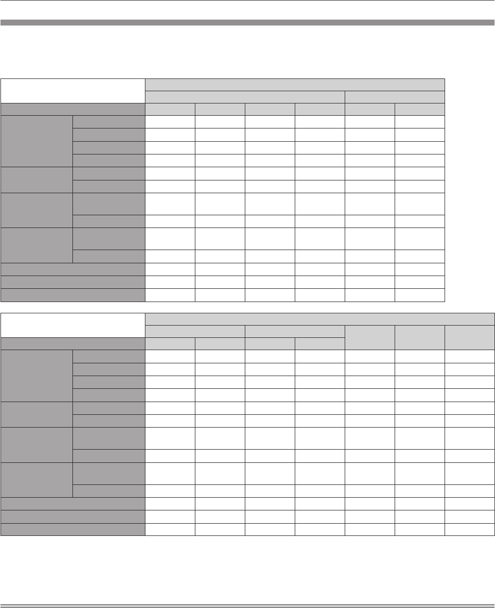
Specications
The specications of the projector are as follows.
Power supply
100 V - 240 V ~ (100 V - 240 V alternating current), 50 Hz/60 Hz
Power consumption
1 200 W (12.0 A - 6.0 A)
When [STANDBY MODE] is set to [ECO]: 0.3 W
When [STANDBY MODE] is set to [NORMAL]: 4 W
DLP chip
Size
PT-RZ12K24.4 mm (0.96") (aspect ratio 16:10)
PT-RS11K24.1 mm (0.95") (aspect ratio 4:3)
Display systemDLP chip x 3, DLP projection system
Number of pixels
PT-RZ12K2 304 000 pixels (1 920 x 1 200 dots)
PT-RS11K1 470 000 pixels (1 400 x 1 050 dots)
LensOptional
Light sourceLaser, 2-bank type
Light output
*1
12 000 lm (ANSI)
Contrast ratio
*1
20 000:1 (when [DYNAMIC CONTRAST] is set to [3])
Color system7 standards (NTSC/NTSC4.43/PAL/PAL-N/PAL-M/SECAM/PAL60)
Projected image size1.78 m (70") to 25.40 m (1 000")
Libble takes abuse of its services very seriously. We're committed to dealing with such abuse according to the laws in your country of residence. When you submit a report, we'll investigate it and take the appropriate action. We'll get back to you only if we require additional details or have more information to share.
Product:
Forumrules
To achieve meaningful questions, we apply the following rules:
First, read the manual;
Check if your question has been asked previously;
Try to ask your question as clearly as possible;
Did you already try to solve the problem? Please mention this;
Is your problem solved by a visitor then let him/her know in this forum;
To give a response to a question or answer, do not use this form but click on the button 'reply to this question';
Your question will be posted here and emailed to our subscribers. Therefore, avoid filling in personal details.
Register
Register getting emails for Panasonic PT-RS11K at:
new questions and answers
new manuals
You will receive an email to register for one or both of the options.
Get your user manual by e-mail
Enter your email address to receive the manual of Panasonic PT-RS11K in the language / languages: English as an attachment in your email.
The manual is 26,64 mb in size.
You will receive the manual in your email within minutes. If you have not received an email, then probably have entered the wrong email address or your mailbox is too full. In addition, it may be that your ISP may have a maximum size for emails to receive.
If you have not received an email with the manual within fifteen minutes, it may be that you have a entered a wrong email address or that your ISP has set a maximum size to receive email that is smaller than the size of the manual.
The email address you have provided is not correct.
Please check the email address and correct it.
Your question is posted on this page
Would you like to receive an email when new answers and questions are posted? Please enter your email address.