597958
7
Zoom out
Zoom in
Previous page
1/108
Next page
Operating Instructions
Camera/VTR
Before operating this product, please read the instructions carefully and save this manual for future use.
Printed in Japan
VQT0N11
F0904W0 -F
@
P
Model No. AJ- P
Model No. AJ- P
2
indicates safety information.
CAUTION
RISK OF ELECTRIC SHOCK
DO NOT OPEN
CAUTION: TO REDUCE THE RISK OF ELECTRIC SHOCK,
DO NOT REMOVE COVER (OR BACK).
NO USER SERVICEABLE PARTS INSIDE.
REFER TO SERVICING TO QUALIFIED SERVICE PERSONNEL.
The lightning flash with arrowhead symbol,
within an equilateral triangle, is intended to
alert the user to the presence of uninsulated
“dangerous voltage” within the product’s
enclosure that may be of sufficient magnitude
to constitute a risk of electric shock to
persons.
The exclamation point within an equilateral
triangle is intended to alert the user to the
presence of important operating and
maintenance (service) instructions in the
literature accompanying the appliance.
CAUTION:
TO REDUCE THE RISK OF FIRE OR SHOCK
HAZARD AND ANNOYING INTERFERENCE,
USE THE RECOMMENDED ACCESSORIES
ONLY.
FCC Note:
This equipment has been tested and found to comply
with the limits for a class A digital device, pursuant to
Part 15 of the FCC Rules. These limits are designed
to provide reasonable protection against harmful
interference when the equipment is operated in a
commercial environment. This equipment generates,
uses, and can radiate radio frequency energy and, if
not installed and used in accordance with the
instruction manual, may cause harmful interference to
radio communications.
Operation of this equipment in a residential area is
likely to cause harmful interference in which case the
user will be required to correct the interference at his
own expense.
Warning:
To assure continued FCC emission limit compliance,
the user must use only shielded interface cables when
connecting to external units. Also any unauthorized
changes or modifications to this equipment could void
the user’s authority to operate it.
ATTENTION:
The product you have purchased is powered by a
nickel cadmium battery which is recyclable. At the
end of it’s useful life, under various state and local
laws, it is illegal to dispose of this battery into your
municipal waste stream.
Please call 1-800-8-BATTERY for information on how
to recycle this battery.
Ni-Cd
RBRC
RBRC
CAUTION:
TO REDUCE THE RISK OF FIRE OR SHOCK
HAZARD, REFER MOUNTING OF THE
OPTIONAL INTERFACE BOARD TO
QUALIFIED SERVICE PERSONNEL.
Replace battery with part No. CR2032 only.
Use of another battery may present a risk of fire or
explosion.
Caution—Battery may explode if mistreated.
Do not recharge, disassemble or dispose of in fire.
WARNING:
OTO REDUCE THE RISK OF FIRE OR SHOCK
HAZARD, DO NOT EXPOSE THIS EQUIPMENT
TO RAIN OR MOISTURE.
OTO REDUCE THE RISK OF FIRE OR SHOCK
HAZARD, KEEP THIS EQUIPMENT AWAY FROM
ALL LIQUIDS—USE AND STORE ONLY IN
LOCATIONS WHICH ARE NOT EXPOSED TO
THE RISK OF DRIPPING OR SPLASHING
LIQUIDS, AND DO NOT PLACE ANY LIQUID
CONTAINERS ON TOP OF THE EQUIPMENT.
The descriptions contained throughout the text of these instructions apply to both the AJ-SDC615 and AJ-SDC905.
However, descriptions which apply solely to the AJ-SDC615 are indicated by ; similarly, descriptions which apply
solely to the AJ-SDC905 are indicated by .
SDC905
SDC615
3
Contents
Chapter 1 General .................................... 5
1-1 Features of the camera unit ...................... 5
1-2 Features of the VTR unit ........................... 6
1-3 System configuration ................................ 7
Chapter 2 Parts and their functions ....... 8
2-1 Power supply and accessory
mounting section ....................................... 8
2-2 Audio function section .............................. 9
2-3 Shooting and recording/playback
function section ....................................... 11
2-4 Menu operation section ........................... 14
2-5 Time code related section ....................... 15
2-6 Warning/status display section .............. 16
2-7 Display window and its displays ............ 16
2-8 Viewfinder section ................................... 18
Chapter 3 Recording and playback ...... 19
3-1 Cassette tapes .......................................... 19
3-2 Basic procedures ..................................... 20
3-3 Scene-to-scene continuity ...................... 22
3-4 NEWS REC function .................. 22
3-5 PRE-RECORDING function ........ 23
3-6 INTERVAL REC function .......................... 23
3-7 RETAKE function ..................................... 25
3-8 Rec-review function ................................. 25
3-9 Normal playback and playback
at different speeds ................................... 25
Chapter 4 Adjustments and settings for
recording ............................... 26
4-1 Adjusting the white balance and
black balance ........................................... 26
4-1-1 Adjusting the white balance ......................... 26
4-1-2 Adjusting the black balance ......................... 28
4-2 Setting the electronic shutter ................. 29
4-2-1 Shutter modes ............................................. 29
4-2-2 Setting the shutter mode and speed ........... 29
4-2-3 Setting the synchro scan mode ................... 30
4-3 Selecting the recording signals and
recording system ..................................... 30
4-3-1 Selecting the recording signals ................... 30
4-3-2 Selecting the recording system ................... 31
4-4 Selecting the audio input signals and
adjusting their recording levels .............. 31
4-4-1 Selecting the audio input signals ................. 31
4-4-2 Adjusting the audio signal recording levels . 31
SDC905
SDC615
4-5 Setting the time data ................................ 32
4-5-1 Setting the user bits ..................................... 32
4-5-2 Setting the internal clock’s date and time .... 33
4-5-3 Setting the time code ................................... 34
4-5-4 Externally locking the time code .................. 34
4-5-5 Setting the UMID information ...................... 35
4-6
Menu displays on the viewfinder screen
....... 36
4-6-1 Menu configuration ...................................... 36
4-6-2 Basic menu operations ................................ 36
4-6-3 Selecting the user menus ............................ 37
4-7 Viewfinder screen status displays ......... 38
4-7-1 Viewfinder lamp displays.............................. 38
4-7-2 Viewfinder screen status display
configuration..................................................38
4-7-3 Selecting the viewfinder screen display
items ............................................................ 38
4-7-4 Display modes and setting
changes/adjustment result messages ......... 44
4-7-5 Setting the marker displays ......................... 44
4-7-6 Setting the camera ID .................................. 44
4-7-7 Mode check screen displays
(MODE CHECK button function) ................. 45
4-7-8 Marker check screen displays
(MARKER SELECT button function) ........... 45
4-7-9 Checking the return video signal on the
viewfinder .................................................... 45
4-8 Menu-driven function setup .................... 46
4-8-1 Setting the USER SW GAIN switching ........ 46
4-8-2 Selecting the video output signals ............... 46
4-8-3 Selecting the F.AUDIO LEVEL
control function ............................................ 47
4-8-4 Allocating functions to the USER MAIN,
USER1 and USER2 buttons ........................ 47
4-8-5 Setting the color temperature manually ....... 48
4-9 Data handling ........................................... 48
4-9-1 Handling the setup card .............................. 48
4-9-2 Setup card operations ................................. 49
4-9-3 How to use the user data ............................ 52
4-9-4 How to use the scene file data .................... 53
4-9-5 How to return the menus settings to the
user standard settings ................................. 56
4-9-6 How to return the menus settings to the
factory standard settings ............................. 56
4-9-7 How to use the lens file data ....................... 56
Chapter 5 Preparation ........................... 57
5-1 Supplying the power ................................ 57
5-1-1 Attaching the battery and setting the
battery type .................................................. 57
5-1-2 Using an AC power supply .......................... 60
5-2 Attaching the viewfinder and adjusting its
position ..................................................... 60
5-3 Attaching the lens and performing the
flange back and white shading
adjustments .............................................. 61
4
Contents
5-4 Audio input signal preparations ............. 66
5-4-1 When using the front microphone ............... 66
5-4-2 When using an external microphone ........... 66
5-4-3 When using a wireless receiver ................... 67
5-4-4 When using an audio component ................ 67
5-5 Mounting the unit on a tripod ................. 68
5-6 Attaching the shoulder strap .................. 68
5-7 Adjusting the position
of the shoulder pad .................................. 68
5-8 Attaching the rain cover .......................... 69
5-9 Connecting the extension control unit
(AJ-EC3P) ................................................. 69
5-10 Attacching the FEONT AUDIO LEVEL
control knob ............................................. 69
Chapter 6 Maintenance and
inspections ........................... 70
6-1 Inspections prior to shooting ................. 70
6-1-1 Preparation for inspections .......................... 70
6-1-2 Inspecting the camera unit .......................... 70
6-1-3 Inspecting the VTR unit ............................... 71
6-1-4 Self-diagnosis function ................................ 72
6-2 Maintenance ............................................. 73
6-2-1 Condensation ............................................... 73
6-2-2 Head cleaning .............................................. 73
6-2-3 Cleaning inside the viewfinder ..................... 73
6-2-4 Phenomena inherent to CCD cameras ....... 73
6-2-5 Replacing the backup battery ...................... 73
6-2-6 Connectors and signals ............................... 74
6-3 Warning system ....................................... 75
6-3-1 Warning description tables .......................... 75
6-3-2 Error codes .................................................. 77
6-3-3 Emergency eject .......................................... 78
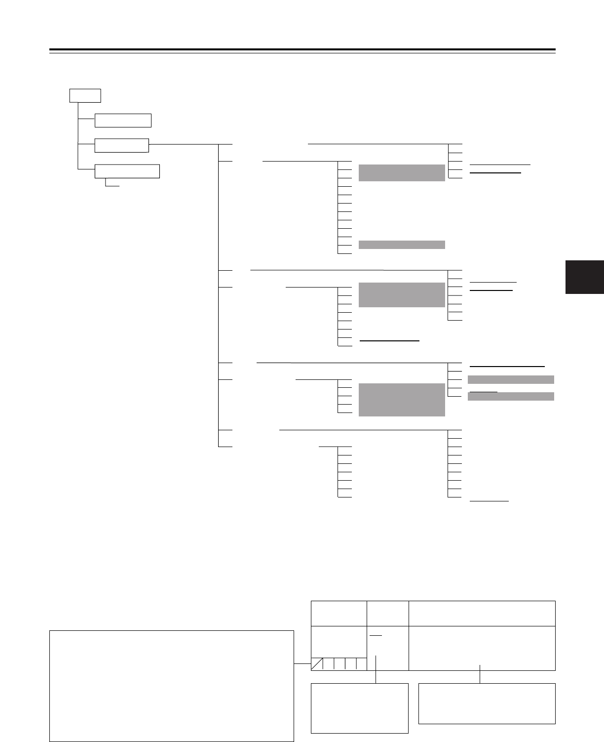
Chapter 7 Menu description tables ...... 79
7-1 Menu configfation .................................... 79
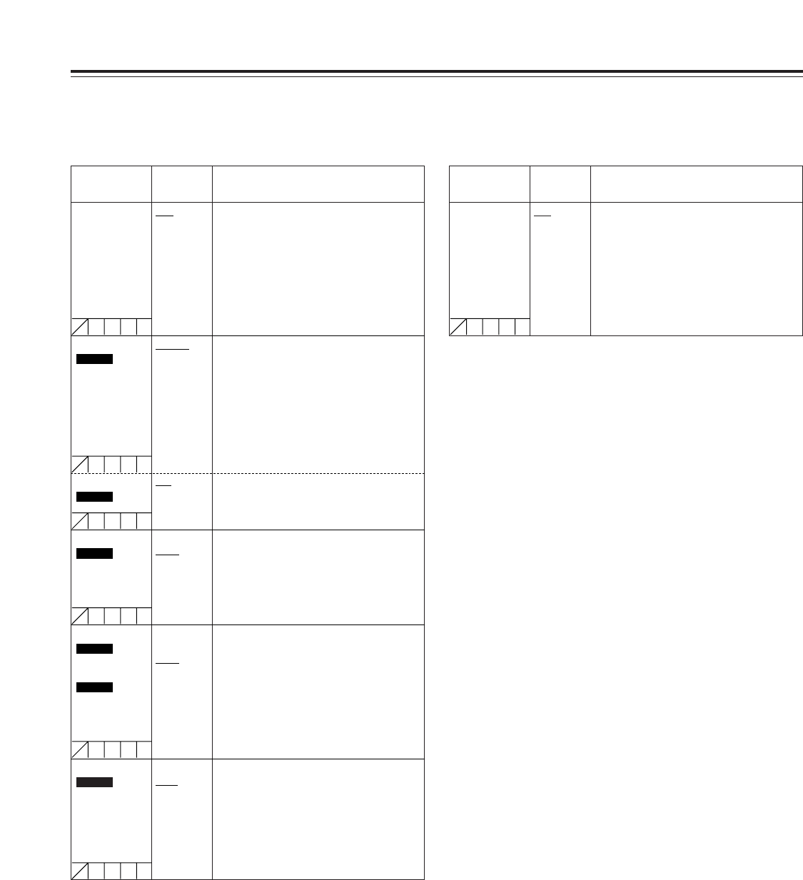
7-2 SYSTEM SETTING .................................... 80
7-2-1 SYSTEM MODE .......................................... 80
7-2-2 OPTION MODE ........................................... 81
7-2-3 REC FUNCTION ......................................... 82
7-2-4 OUTPUT SEL .............................................. 83
7-2-5 GENLOCK ................................................... 83
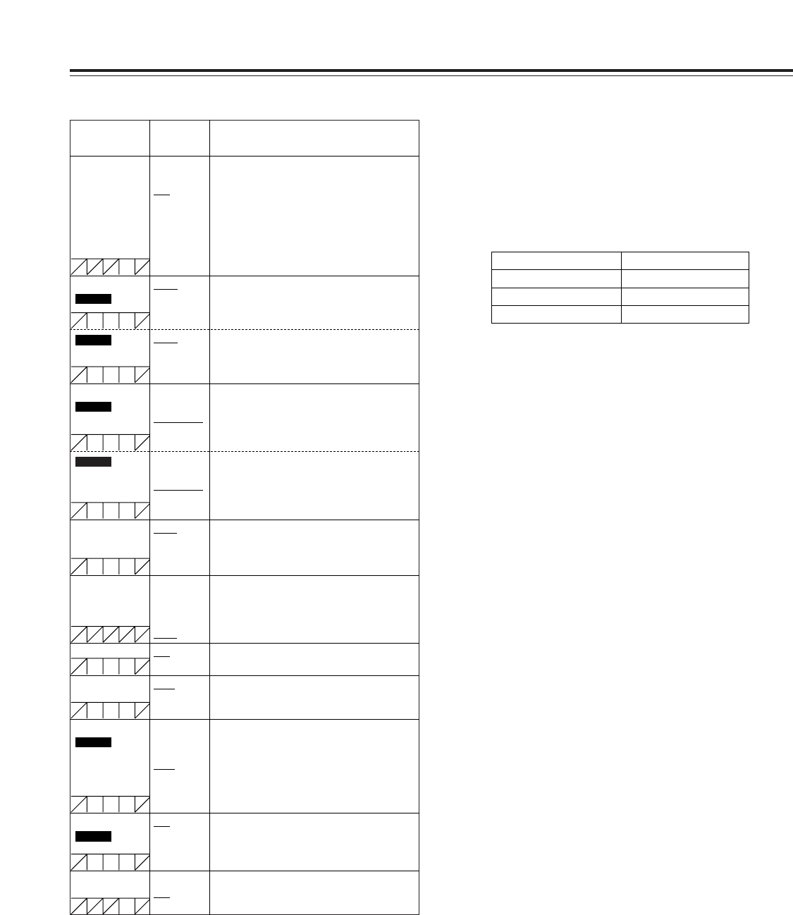
7-3 PAINT ........................................................ 84
7-3-1 ROP ............................................................. 84
7-3-2 MATRIX ....................................................... 84
7-3-3 COLOR CORRECTION .............................. 85
7-3-4 LOW SETTING ............................................ 85
7-3-5 MID SETTING ............................................. 86
7-3-6 HIGH SETTING ........................................... 86
7-3-7 ADDTIONAL DTL ........................................ 87
7-3-8 SKIN TONE DTL ......................................... 87
7-3-9 KNEE/LEVEL .............................................. 88
7-3-10 GAMMA ....................................................... 88
7-3-11 FLARE ......................................................... 88
7-3-12 CAMERA SETTING .................................... 89
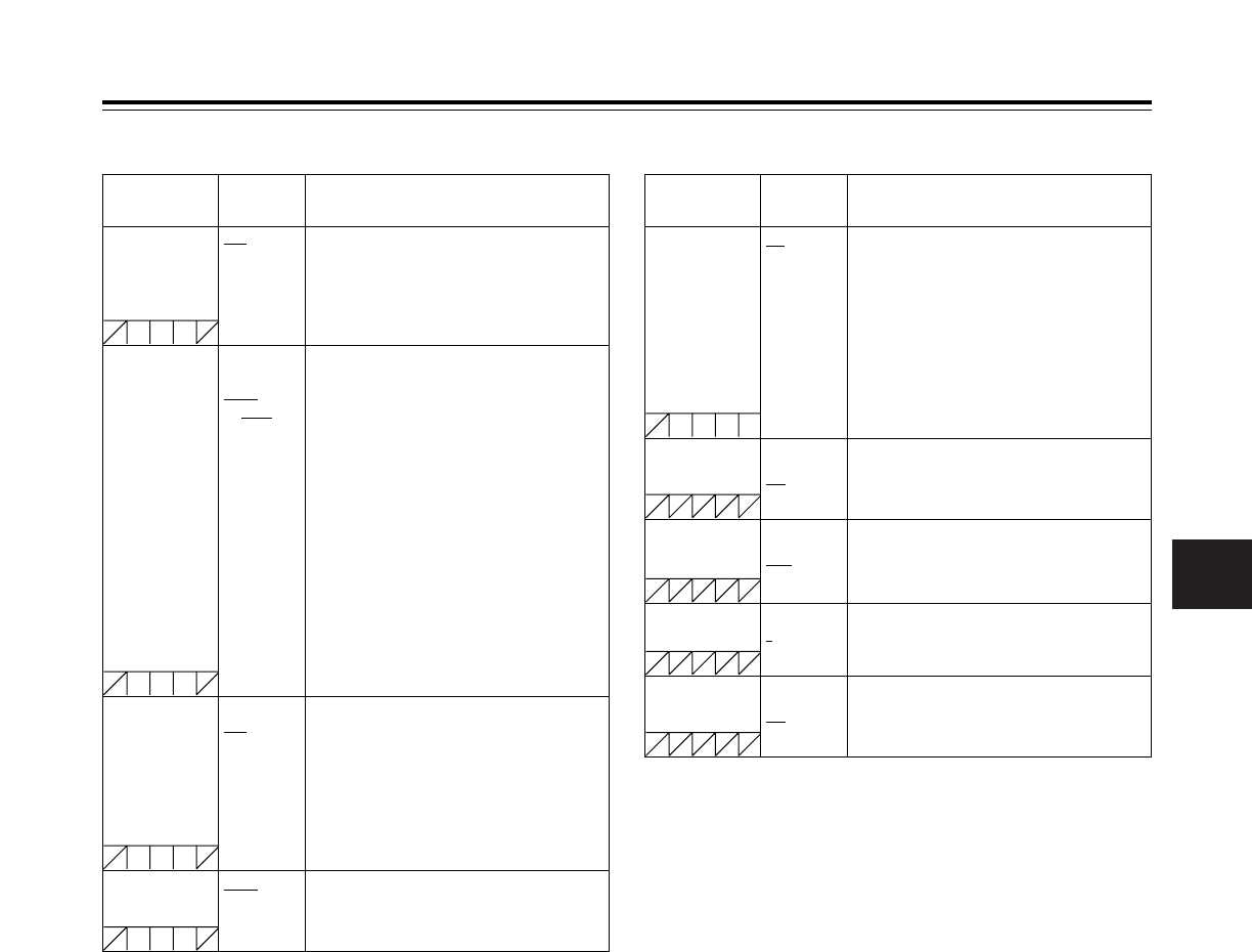
7-4 VF .............................................................. 89
7-4-1 VF DISPLAYS ............................................. 89
7-4-2 VF MARKER ............................................... 90
7-4-3 USER BOX .................................................. 90
7-4-4 VF INDICATOR1 ......................................... 90
7-4-5 VF INDICATOR2 ......................................... 91
7-4-6 MODE CHECK IND ..................................... 91
7-4-7 !LED ............................................................ 91
7-5 OPERATION .............................................. 92
7-5-1 CAMERA ID ................................................ 92
7-5-2 SHUTTER SPEED ...................................... 92
7-5-3 SHUTTER SELECT .................................... 92
7-5-4 USER SW .................................................... 93
7-5-5 SW MODE ................................................... 93
7-5-6 WHITE BALANCE MODE ........................... 94
7-5-7 USER SW GAIN .......................................... 94
7-5-8 IRIS ............................................................. 95
7-6 FILE ........................................................... 95
7-6-1 CARD READ/WRITE ................................... 95
7-6-2 CARD R/W SELECT ................................... 95
7-6-3 LENS FILE .................................................. 96
7-6-4 SCENE ........................................................ 96
7-6-5 INITIALIZE ................................................... 96
7-7 MAINTENANCE ........................................ 96
7-7-1 SYSTEM CHECK ........................................ 96
7-7-2 DIAGNOSTIC .............................................. 96
7-7-3 LENS ADJ ................................................... 96
7-7-4 BLACK SHADING ....................................... 97
7-7-5 WHITE SHADING ....................................... 97
7-8 VTR MENU ................................................ 97
7-8-1 VTR FUNCTION .......................................... 97
7-8-2 BATTERY/TYPE ......................................... 98
7-8-3 BATTERY SETTING1 ................................. 98
7-8-4 BATTERY SETTING2 ............................... 100
7-8-5 MIC/AUDIO1 ............................................. 101
7-8-6 MIC/AUDIO2 ............................................. 102
7-8-7 TC/UB ........................................................ 102
7-8-8 UMID SET/INFO ........................................ 103
7-8-9 VTR DIAG ................................................. 103
7-9 OPTION MENU......................................... 104
7-9-1 OPTION ..................................................... 104
Chapter 8 Specifications ..................... 105
UniSlot
®
is a registered trademark of Ikegami Tsusinki co., Ltd.
Chapter 1 General
1
5
3 CCDs with a 2/3-inch on-chip lens
Aspect ratios of 16:9 and 4:3 are supported.
Storage type high-sensitivity function
The unit comes with a storage type gain increase function.
This is a function that makes it possible to achieve a higher
sensitivity of up to 20 dB above the regular gain increase.
<Note>
Due to the properties inherent to the unit’s CCD image
sensors, the top left part of the screen may become slightly
brighter when the cumulative gain is increased.
Digital zoom function
The unit is equipped with a digital zoom employing function.
This function is particularly useful when zooming further in
on a subject.
12-bit A/D conversion digital signal processing
circuitry
The analog images are processed into digital data by a 12-
bit A/D converter with sampling frequencies of 18 MHz, and
by operating the signal processor using the 36 MHz
frequency, it is possible to reproduce images which are
more finely detailed and achieve improvements in stability
and reliability.
12-axis independent color correction function
Serving as a paint function, this facility enables the colors
for 12 axes to be compensated for independently and is
very useful for creating finely detailed images.
Data control function
When the unit is used on its own, one set of user data and
four sets of scene file data can be registered. Further, by
using an SD card or a Multimedia Card (optional accessory)
as the setup card, up to eight sets of setup data can be
stored.
<Note>
SD card and MultiMedia card used in this unit do not
comply with the SD standard. Do not use cards formatted
using this unit with other camera-recorders. Further, NTFS
and FAT32 formatted cards cannot be used with this unit.
The recommended size for SD cards is 8 MB or more and 4
MB or more for MultiMedia cards.
MARKER SELECT button
At the front of the unit is a button for checking the
information concerning the markers on the viewfinder
screen. This is useful for checking the picture angle, for
instance, during shooting.
ECU supported
The unit supports the AJ-EC3P extension control unit.
Single-action shoulder pad slide function
It is now possible to adjust the position where the unit is
optimally balanced for operation using a single-touch action.
This means that the operator can easily optimize the unit’s
balance when the lens, battery and other peripheral camera
devices have been installed on the unit.
1-1 Features of the camera unit
The models AJ-SDC615 and AJ-SDC905 are camera recorders featuring three CCD image sensors which each have a 2/3-inch
on-chip lens.
The AJ-SDC905 supports both the DVCPRO and DVCPRO50 formats. (The AJ-SDC615 supports only the
DVCPRO format.)
Both camera recorders feature a compact size, light weight, low power consumption, high image quality, high sensitivity,
excellent mobility and outstanding dust-proof and moisture-proof characteristics.
They are ideally suited not only for news gathering but also for a wide range of production applications.
Both their camera and VTR units employ digital signal processing technology to achieve an improved image quality and stability,
and they configure a system which enables data management using setup cards.
An IEEE 1394 connector is provided as a standard feature for increased mobility.
SDC615SDC905
Chapter 1 General
6
DVCPRO and DVCPRO50 formats supported
The VTR unit compresses the images using a component
digital recording system that uses the latest compression
technology, and for the sound it employs non-compression
PCM recording with an excellent signal-to-noise ratio,
frequency band, waveform characteristics and reproduction
characteristics of the finely detailed areas. As a result, both
the picture quality and sound quality are taken to new
heights of excellence.
A choice of recording formats tailored to the application at
hand is offered: the DVCPRO50 format when priority is
required to be given to the picture quality, and the DVCPRO
format when economy is to be given precedence.
DVCPRO format supported
The VTR unit compresses the images using a component
digital recording system that employs the latest
compression technology, and for the sound it uses non-
compression PCM recording with an excellent signal-to-
noise ratio, frequency band, waveform characteristics and
reproduction characteristics of the finely detailed areas. As
a result, both the picture quality and sound quality are taken
to new heights of excellence.
Power-saving management function
In order to reduce its power consumption efficiently, the unit
has a function that shuts down circuitry that is not required
for the particular VTR mode established at the time. This
enables the user to perform operations while conserving
power.
Pre-recording function featured
This function makes it possible to
record the pictures and sound up to 6 seconds ahead of the
point in time when recording is commenced by pressing the
VTR START button or VTR button on the lens. It is
effective in preventing shots from being missed.
Interval REC function provided
This unit is capable of interval shooting.
The AJ-SDC905 makes it possible to conduct
recording in intervals with a minimum recording time in
increments of one frame.
The AJ-SDC615 makes it possible to conduct
recording in intervals with a recording time of 2 seconds or
more.
This is particularly useful for shooting science and nature
programs.
Furthermore, when the unit is used for one-shot recording,
frame-by-frame shooting is easily accomplished.
SDC615
SDC905
SDC905
SDC615
SDC905
NEWS REC function
This function especially supports shooting in the context of
news gathering or documentary filming to ensure that
shutter opportunities are not passed up.
By controlling the start key acknowledgment time, the unit
can continuously record without the user having to interrupt
the recording: this safeguards against the failure to record
those precious moments—a failure that occurs when
recording is resumed after it has been shut down
temporarily.
RETAKE function
This function is for not leaving behind superfluous cuts
when a cut turns out to be no good during the shooting of
news, reports or art programmes. By cutting down on the
time taken for copying onto the work tape, for instance, this
function is very effective in achieving economical operation.
Users should remember to handle this function very
carefully.
Input signals of 2 separate audio channels
supported
The unit enables the audio input signals in two channels to
be selected separately. Further, the level of the signal in
each channel can be monitored on the LCD display window.
Front audio level control
The unit’s front panel is equipped with a control for adjusting
the audio recording level. This is useful when the user is
filming on his or her own and the audio level needs to be
adjusted. It also is possible to cancel the effect of this control.
UniSlot
®
wireless receiver
The unit’s construction supports a slot-in wireless receiver
which is available as an optional accessory.
Built-in DOLBY NR system
The CUE audio recording circuitry contains a Dolby B noise
reduction circuit.
Frame-to-frame continuity
Simply by pressing the VTR START button or VTR button
on the lens, the continuity from one frame to the next is
assured with a precision of +1 frame or less.
Rec-review function
This automatically rewinds the tape for the last 2 to 10
seconds recorded and plays back the recording. This
enables the recording to be monitored without delay.
Dolby noise reduction manufactured under license
from Dolby Laboratories Licensing Corporation.
“DOLBY” and the double-D symbol
Î
are trademarks
of Dolby Laboratories Licensing Corporation.
SDC615
1-2 Features of the VTR unit
26-pin camera
adapter:
AJ-CA905G
26-pin cable:
AJ-C26050G (50 m),
AJ-C26100G (100 m)
Remote control
unit:
AJ-RC905
V-mount type battery plate
NP-1 type battery holder
BP-90 type battery holder
PRO14, TRIM14,
HYTRON50/100/120,
DIONIC90/160
ENDURA50/80, BP-L60/90
NP-L50
BP-H120, HP-90L
Battery
Chapter 1 General
1
7
Microphone kit:
AJ-MC700
UniSlot
®
wireless
microphone receiver:
Sennheiser EK3041
Microphone holder:
AJ-MH700
Lens
(Bayonet type):
Fujinon, Canon
Rain cover:
SHAN-RC700
Soft carry case:
AJ-SC900
(Can not purchase in
some area.)
Hard carry case:
AJ-HT901
AC adapter:
AJ-B75
Devices compliant with
IEEE 1394 standard
Cassette tapes:
AJ-5P23MP
AJ-5P33MP
AJ-P12MP
AJ-P24MP
AJ-P33MP
AJ-P66MP
Cleaning tape:
AJ-CL12MP
Extension control unit:
AJ-EC3P
Viewfinders:
AJ-VF15B
AJ-VF20WB
GPS unit:
AJ-GPS900G
Tripod attachment:
SHAN-TM700
Video camera-recorder:
AJ-SDC615
AJ-SDC905
1-3 System configuration
SD memory cards
Multimedia cards
Built-in time code generator/reader
This enables the time code information to be recorded on
the dedicated sub-code track and played back.
Metadata supported
The unit allows information from the AJ-GPS900G GPS unit
to be recorded on tape as the metadata UMID information.
This is useful when it comes to managing on-tape
information.
DVCPRO (IEEE 1394 digital input/output)
connector provided
The unit is standard equipped with an input/output
connector for signals complying with the IEEE 1394
standard.
This connector can be connected with an external unit using
an IEEE 1394 cable.
Chapter 2 Parts and their functions
8
1 POWER switch
This switch turns the power ON and OFF.
2 Battery mount
This is for attaching the Anton Bauer battery pack.
3 DC IN (external power input) socket (XLR, 4-pin)
When operating this unit using an AC power source, this
socket is connected to the model AJ-B75 AC adapter
(optional accessory).
4 BREAKER switch
If an excessively high current flows inside the unit due to
some problem or other, the circuit breaker is tripped and
the power is automatically turned off to protect the unit.
Push this button in after an inspection has been conducted
or repairs performed inside the unit by a qualified service
person. If there are no problems, the power will come back
on.
5 GPS connector
The connector from AJ-GPS900G, a GPS unit available as
an optional accessory, is connected here.
6 Shoulder belt fittings
The shoulder belt is attached here.
7 Light shoe
Use this to attach the video light, etc.
8 Lens mount (bayonet type)
The lens is attached to this mount.
9 Lens lever
This lever is tightened to secure the lens after it has been
attached to the lens mount.
: Lens mount cap
To remove the cap, push the lens lever 9 up.
Keep the cap in place while the lens is not attached.
; Lens cable/microphone cable clamp
This clamp is for anchoring the lens cable or microphone
cable.
< Tripod mount
Mount the tripod attachment (SHAN-TM700), available as
an optional accessory, when the unit is to be anchored to a
tripod.
= LENS jack (12-pin)
The connecting cord of the lens is connected to this jack.
For further details on the lenses that can be used, refer to
the operating instructions of the lenses concerned.
> Easy-to-adjust shoulder pad
The position of the shoulder pad can be adjusted backward
or forward so that the unit is balanced when it is carried on
the user’s shoulder.
1
34
6
2
5 7
8
9
:
; <=>
6
2-1 Power supply and accessory mounting section
Chapter 2 Parts and their functions
2
9
2-2 Audio function section (input system)
1
2
5
6
9@? ?8
= < > 73; :
4
1 MIC IN (microphone input) jack (XLR, 3-pin)
Connect the microphone (optional accessory) here. The
power for the microphone is supplied from this jack.
2 AUDIO LEVEL CH1/CH2 (audio channel 1 & 2 recording
level adjustment) controls
When the AUDIO SELECT CH1/CH2 switch 3 is set to
MAN, the recording level of audio channels 1 and 2 can be
adjusted using these controls.
The controls come with a locking mechanism. Therefore, to
adjust the recording level, simultaneously push in and turn
the controls.
3 AUDIO SELECT CH1/CH2 (audio channel 1 & 2
automatic/manual level adjustment selector) switch
This is used to select the method for adjusting the
recording levels of audio channels 1 and 2.
AUTO : Set here for automatic adjustment.
MAN : Set here for manual adjustment.
4 AUDIO IN (audio input selector) switch
These are used to select the input signals to be recorded
on audio channels 1 and 2.
FRONT :
The input signals supplied from the microphone which
has been connected to the MIC IN jack 1 are recorded.
W.L. (wireless) :
The input signals from the slot-in wireless microphone
receiver are recorded.
REAR :
The audio input signals supplied from the audio
component which has been connected to the AUDIO IN
CH1/CH2 connectors 5 are recorded.
5 AUDIO IN CH1/CH2 (audio input channel 1 & 2)
connectors (XLR, 3-pin)
An audio component or microphones are connected here.
6 LINE/MIC/+48V (line input/mic input/mic input + 48V)
selector switch
This is used to switch the audio input signals from the
audio component which has been connected to the AUDIO
IN CH1/CH2 connectors 5.
LINE : The audio input signals from the audio component
serving as the line input are selected.
MIC : The audio input signals from the internal power
supply type of microphone are selected. (The
phantom mic power is not supplied from the unit.)
+48V : The audio input signals from the external power
supply type of microphone are selected. (The
phantom mic power is supplied from the unit.)
7 Wireless receiver slot
The UniSlot
®
wireless receiver (optional accessory) can be
attached here.
8 FRONT AUDIO LEVEL (audio recording level
adjustment) control
This enables the recording level of audio channels 1 and 2
to be adjusted. This level can be adjusted regardless of
the setting position of the AUDIO SELECT switch.
When the <MIC/AUDIO1> screen is opened from the VTR
MENU page by performing a menu operation, whether to
enable or disable the operation of this level control can be
set using the FRONT VR CH1 and FRONT VR CH2 setting
items.
O The same signals as for CH1 are recorded on audio track CH3.
Similarly, the same signals as for CH2 are recorded on audio track
CH4.
O The signals are recorded on two channels (CH1 and CH2) when the
DVCPRO format (25 Mbps) is set.
SDC905
The mixed signals of audio channels 1 and 2 are output
to the remote control unit (AJ-RC905).
The signals are output now as is without the adjustment
of their level, etc.
Chapter 2 Parts and their functions
10
2-2 Audio function section (output system)
2 Either STEREO or MIX can be selected as the setting for the MONITOR
SELECT item by opening the <MIC/AUDIO2> screen from the VTR
MENU page by performing a menu operation.
CH1/3 Audio channel 1 Audio channel 3
MONITOR SELECT CH1/2OCH3/4 selector switch
CH1/2 CH3/4
ST
Stereo
2
signals of audio
channels 1 and 2
Stereo
2
signals of audio
channels 3 and 4
CH2/4 Audio channel 2 Audio channel 4
9 AUDIO OUT connector (XLR, 5-pin)
The audio signals recorded on audio channels 1 and 2 or
audio channels 3 and 4 are output from this connector.
With the AJ-SDC905 , the signals to be output
can be selected using the MONITOR SELECT
CH1/2OCH3/4 selector switch.
: MONITOR SELECT (audio channel)
CH1/2OCH3/4 selector switch
This is used to select the audio channels whose signals are
to be output to the speaker, earphone and AUDIO OUT
connector.
CH1/2 : The signals of audio channels 1 and 2 are output.
CH3/4 : The signals of audio channels 3 and 4 are output.
In addition, the channel indications for the audio level
meters appearing in the display window and viewfinder
change when this switch is operated.
MONITOR SELECT (stereo/mix)
STOMIX selector switch
This is used to select the sound which is to be output to the
speaker, earphone and AUDIO OUT connector.
ST: The stereo audio signals of channels 1 and 2 are
output.
MIX: The mixed audio signals of channels 1 and 2 are
output.
; MONITOR SELECT (audio selection)
CH1/3OSTOCH2/4 selector switch
This is linked with the MONITOR SELECT CH1/2OCH3/4
selector switch and used to select the sound which is to be
output from the speaker, earphone and AUDIO OUT
connector.
CH1/3 : The signals of audio channel 1 or 3 are output.
ST : The stereo audio signals of either audio channels
1 and 2 or audio channels 3 and 4 are output.
Using a menu setting, the stereo signals can be
changed to MIX signals.
CH2/4 : The signals of audio channel 2 or 4 are output.
SDC905
SDC615
SDC905
SDC905
CH1 Audio channel 1 Audio channel 1
MONITOR SELECT STOMIX selector switch
ST MIX
1/2
Stereo signals of audio
channels 1 and 2
Mixed signals of audio
channels 1 and 2
CH2 Audio channel 2 Audio channel 2
< MONITOR (volume) control
This is used to adjust the volume of the monitor speaker or
earphone.
= ALARM (warning alarm volume adjustment)
This is used to adjust the volume of the warning alarms
from the earphones which have been connected to the
speaker > or PHONES jack ?.
The warning alarms are not audible when this control is at
its lowest setting.
> Speaker
The EE sound during recording or the playback sound
during playback can be monitored through this speaker.
The warning alarms are output in synchronization with the
flashing or lighting of the warning lamps and warning
displays.
The sound heard from the speaker is automatically cut off
when earphones are connected to the PHONES jack ?.
? PHONES (earphones) jack (mini jack)
This is the earphone (stereo) jack which is used to monitor
the audio signals. When earphones are connected, the
sound from the speaker is automatically cut off. The sound
which is output from the two jacks (front and rear) is the
same.
@ DC OUT (DC power supply) output socket
This normally serves as the DC 12 V output socket. A
current of approximately 1 A can be supplied.
MONITOR SELECT (audio selection)
CH1O1/2OCH2 selector switch
This is linked with the MONITOR SELECT STOMIX
selector switch and used to select the sound which is to be
output from the speaker, earphone and AUDIO OUT
connector.
CH1: The signals of audio channel 1 are output.
1/2: The stereo audio signals of audio channels 1 and 2
are output. The stereo signals can be changed into
mixed signals using the MONITOR SELECT
STOMIX selector switch.
CH2: The signals of audio channel 2 are output.
SDC615
Chapter 2 Parts and their functions
2
11
1 9 84
@
765< >2 = BAC I
?
;
:
3
ª
6
5
1/;
EJECT
/
REW FF
/
STOP PLAY
/
PAUSE
D G H
E F
2-3 Shooting and recording/
playback
function section
Shooting and recording (camera unit)
1 FILTER (filter switching) controls
These are used to select the filter in accordance with the
subjects brightness and color temperature.
1: 3200 K (transparent) 2: 5600 K+1/8 ND
3: 5600 K 4: 5600 K+1/64 ND
2 AUTO W/B (white/black) BAL switch
AWB : The white balance is automatically adjusted. When
the AWB memory selector switch on the side panel
is set to A or B and then the AUTO W/B BAL switch
is operated, the adjustment value is recorded in the
memory. When VAR has been selected as the
setting for AWB A and/or AWB B menus, the value
will be the one set in the menu and this switch will
not function. Note that this switch will also not
function at the PRST position.
ABB : The black balance is automatically adjusted.
If the AUTO W/B BAL switch is held down at the
ABB position for 5 or more seconds, the black
shading is compensated automatically.
<Note>
When white balance or black balance are being
automatically adjusted and the switch is pressed again to
either the AWB side or to the ABB side, the automatic
adjustment for the side pressed will be stopped.
The adjusted value in this case is the value before
automatic adjustment was performed.
3 SHUTTER switch
This is the ON/OFF selector switch of the electronic
shutter.
OFF : The electronic shutter does not operate.
ON : The electronic shutter operates.
SEL : This is used when the electronic shutter speed is to
be changed.
The switch is a non-locking type. The shutter speed
changes each time it is operated. For further details, refer
to 4-2 Setting the electronic shutter.
4 Synchro scan adjustment switches
These switches become effective when the shutter switch
3 is set to ON and SYNCHRO SCAN is selected. They
are used to adjust the synchro scan speed.
When the “–” switch is pressed, the shutter speed is
reduced; conversely, when the + switch is pressed, it is
increased.
During personal computer monitor shooting, etc. adjust
these switches to the positions where the horizontal bar
noise inside the viewfinder is decreased.
5 GAIN selector switch
This is used to select the gain of the video amplifier in
accordance with the lighting conditions prevailing at the
time of the shooting. The gain values for the L, M and H
settings are set ahead of time on the setting menu. Their
factory settings are 0 dB, 9 dB and 18 dB, respectively.
$ Examples of filter selection
Shooting conditions Filter
Sunrise, sunset, inside a studio 1 (3200 K)
Outdoors under cloudy or rainy skies 3 (5600 K)
Outdoors under a clear sky 2 (5600 K+1/8 ND)
or
4 (5600 K+1/64 ND)
Snowscapes, high mountains, seashores
or other perfectly clear scenery
4 (5600 K+1/64 ND)
Chapter 2 Parts and their functions
12
AUTO KNEE function
When shooting with the level set to people or scenes against a high-
brightness background, the background will be whitened out, and the
buildings and scene in the background will be blurred. If the AUTO KNEE
function is activated at times like this, the background will be reproduced
clearly. This function is effective for shooting in the following situations:
When shooting people in the shade under a clear sky
When simultaneously shooting people in a car or indoors and the
outside scenery through a window
When shooting scenes with a strong contrast
6 OUTPUT/AUTO KNEE selector switch
This switch selects the video signals which are to be output
from the camera unit to the VTR unit, viewfinder and/or
video monitor.
CAM. AUTO KNEE ON:
The images shot by the camera are output. The AUTO
KNEE circuit operates.
CAM. AUTO KNEE OFF:
The images shot by the camera are output. The
MANUAL KNEE circuit operates.
BARS:
Color bar signals are output. The AUTO KNEE circuit
does not operate.
7 WHITE BAL (white balance memory selector) switch
This is used to select the method used to adjust the white
balance.
PRST:
Set the switch to this position at times when, for
instance, there is no time to adjust the white balance.
The factory setting for the white balance is 3200K, but
this can be changed to any other value by a menu
setting. For details, refer to 4-8-5 Setting the color
temperature manually.
A or B:
When the AUTO W/B BAL switch 2 is set to AWB, the
white balance is automatically adjusted, and the
adjusted value is stored in memory A or memory B. For
details, refer to 4-1-1 Ajusting the white balance.
As the factory setting, the settings are to be allocated to
the memory. Using a menu setting, it is also possible to
allocate the setting for the auto tracking white balance
(ATW) performed with the automatic tracking system to
memory B or allocate the color temperatures of the
user's choice to memory A and memory B. For details,
refer to 4-8-5 Setting the color temperature manually.
8 MODE CHECK button
Each time this button is pressed, one of the four screen
pages (STATUS screen display, !LED screen display,
FUNCTION screen display and AUDIO screen display) is
selected and displayed on the viewfinder to indicate the
cameras settings.
This does not affect the output signals of the camera.
9 MARKER SELECT button
This is used to select the marker information displays on
the viewfinder screen. Each time it is pressed, the two
marker information display screens set by the menu are
switched in the following sequence: A (A marker display) 5
B (B marker display) 5 OFF (no marker display) 5 A, and
so on repeatedly. Note that when the power is switched
ON, the display on the viewfinder screen immediately
before the power was switched OFF will appear.
For details, refer to 4-7-8 Marker check screen displays.
: USER MAIN, USER 1 and USER 2 buttons
A user setting can be allocated to each of these buttons
using the setting menu. When a button is pressed, the
user setting mode allocated to it is selected.
When the button is pressed again, the selected mode is
released.
For details, refer to 4-8-4 Allocating functions to the USER
MAIN, USER1 and USER2 buttons.
Shooting and recording (VTR unit)
; VTR START/STOP button
When this is pressed, recording starts; when it is pressed
again, recording stops. This button functions in the same
way as the lens VTR button.
< VTR SAVE/STBY (tape protection) switch
This is used to select the power supply mode when the
VTR has temporarily stopped recording (REC PAUSE
mode).
SAVE: This is the tape protection mode. The cylinder is
stopped in the half-loading status.
Less power is consumed than at the STBY
position, and the operating time provided by the
battery is prolonged. Compared with the STBY
position, it takes longer for recording to commence
after the VTR START button ; has been pressed.
When the switch is set to this position, the VTR
SAVE lamp inside the viewfinder lights.
STBY : At this position, recording is commenced as soon
as the VTR START button is pressed.
<Note>
When the prescribed amount of time has elapsed in the
STBY mode, the unit is automatically set to the SAVE
mode. To return the unit to the STBY mode, set the VTR
SAVE/STBY switch to SAVE, and then again to the STBY
position.
Chapter 2 Parts and their functions
2
13
= OUTPUT SEL (output signal selection) switch
This is used to select the signals output from the VIDEO
OUT connector and MON OUT connector.
VTR : In the recording or other EE mode, the camera
images are output from the connectors; in the
playback or other VV mode, it is the VTRs playback
signals which are output.
CAM : The camera images are output at all times.
OFF : The video output is stopped and the power
reduction mode is established.
Furthermore, the audio output signals are synchronized
with the video signals as well.
For details on the video output, refer to 4-8-2 Selecting the
video output signals.
<Notes>
O During recording, the output signals are not switched
even when the position of this switch is changed. They
are switched when the recording operation is stopped.
O When the signals input to the GENLOCK IN connector
or DVCPRO connector are selected as the signals to be
recorded, the switch setting will be the same as at the
VTR position even if the switch is set at the CAM
position.
> VIDEO OUT CHARACTER switch
This is used to control the superimposing of the characters
onto the images which are output from the VIDEO OUT
connector.
ON : The characters are superimposed onto the images.
OFF : The characters are not superimposed onto the
images.
For details on the character types, refer to 4-8-2 Selecting
the video output signals.
? VIDEO OUT (video signal output) connector
This is the video signal output connector. The video
signals linked to the setting of the OUTPUT SEL switch are
output from here.
@ ECU REMOTE (remote control) connector
The AJ-EC3P extension control unit (optional accessory) is
connected here.
A MON OUT (monitor output) connector
This is the connector for outputting the video signal which
is used for monitoring. The video signals linked to the
setting of the OUTPUT SEL switch are output from here.
Whether characters are to be superimposed onto the
images output from the VIDEO OUT connector can be
selected separately using the internal menu.
For details, refer to 4-8-2 Selecting the video output
signals.
B GENLOCK IN connector
The reference signal is input to this connector when
genlock is to be established with the camera unit or when
the time code is to be externally locked. This signal can
also be used as the return signal.
The connector serves as a video input connector for
receiving the video signals from an external unit when the
<SYSTEM MODE> screen is opened from the SYSTEM
SETTING page by performing menu operations and VIDEO
is selected as the REC SIGNAL menu item setting.
<Note>
A standard VBS signal (a composite signal including a
burst signal) should be supplied as the input reference
signal.
C DVCPRO connector (6-pin)
This is the input/output connector for signals which comply
with the IEEE 1394 standard. It can be connected with an
external unit using an IEEE 1394 cable.
<Notes>
O Power is not supplied from the unit.
O Before proceeding to connect or disconnect the DV
cable (IEEE1394), be absolutely sure to turn off the
power of the units that are to be connected or
disconnected using this cable.
O Before proceeding to connect
the unit which uses a 6-pin type
of DV connector, carefully
check the shape of the
connectors on the DV cable
and unit. Connecting a
connector upside down may
damage the parts inside the
camera-recorder and cause
malfunctioning.
Always connect the DV cable to the unit with the 6-pin
type DV connector first.
O When recording signals from an external unit, first check
that video signals are supplied.
O While signals from an external unit are being recorded,
do not operate the external unit or disconnect any of its
cables. This will stop the output, which may result in the
signals not being recognized when recording is
resumed.
O You can connect a digital video unit equipped with a DV
connector and digitally transfer video and audio signals
as well as time codes and other information.
O When a DV cable has been connected to the DV
connector, do not apply any strong external force as this
may damage the connector.
D EJECT button
This is pressed to insert or eject the cassette.
E STOP button
This is pressed to stop the tape travel.
6-pin type
4-pin type
Chapter 2 Parts and their functions
14
2-4 Menu operation section
1 MENU button
This is used to switch the menu ON and OFF.
2 JOG dial button
This is used to select the menu items and perform settings
when the MENU button 1 is at the ON position.
3 Setup card insertion slot
This is where the SD card (optional accessory) or
Multimedia card (optional accessory) is inserted into the
unit.
4 BUSY (operation mode display) lamp
This lamp shows the operation mode of the setup card. It
lights during operation.
<Note>
When this lamp is lighted, refrain from inserting or
removing the card.
F PLAY/PAUSE button
This is pressed to view the playback picture on the
viewfinder screen or using a color video monitor. The
buttons lamp comes on during playback.
When it is pressed during playback, the unit is set to pause
in the playback mode (PLAY PAUSE), and the buttons
lamp flashes. If the unit is left in the pause mode for two
minutes, it automatically changes to the stop (STOP)
mode.
G REW (rewind) button and lamp
When this button is pressed during stop, the tape is
reviewed at high speed. Its lamp lights at this time.
When it is pressed during playback or pause, the tape is
reviewed at approximately 4 times the normal tape speed.
Both the PLAY lamp and REW lamp light at this time.
H FF (fast forward) button and lamp
When this button is pressed during stop, the tape is cued at
high speed. Its lamp lights at this time.
When it is pressed during playback or pause, the tape is
cued at approximately 4 times the normal tape speed.
Both the PLAY lamp and FF lamp light at this time.
I EMERGENCY screw (inside rubber cap)
If the cassette does not eject even when the EJECT button
is pressed, use a screwdriver or similar implement to push
and turn the EMERGENCY screw at the same time: this
will cause the cassette to be ejected.
For details, refer to 6-3-3 Emergency eject.
Chapter 2 Parts and their functions
2
15
3 21
9
64 5
78
2-5 Time code related section
1 GENLOCK IN connector (BNC)
The reference signal is input to this connector when
genlock is to be established with the camera unit or when
the time code is to be externally locked.
2 TC IN connector (BNC)
Supply the time code which will serve as the reference to
this connector when externally locking the time code.
3 TC OUT connector (BNC)
To lock the time code of an external VTR to the units time
code, connect this connector to the time code input (TC IN)
connector on the external VTR.
4 HOLD button
The time data display of the counter display section which
was on the screen at the moment when this button is
pressed is held. (However, the time code generator keeps
running.) When the button is pressed again, the hold
status is released.
It is used, for instance, to find out the time code or CTL
counter value at which a particular scene was shot.
5 RESET button
This is used to reset the time data on the counter display
section to 00:00:00:00. If it is pressed while the TCG
switch 9 is at the SET position, the time code data and
user bits data are respectively reset to 00:00:00:00.
6 DISPLAY switch
This is used to display the time code, CTL or user bits on
the counter display section depending on the setting
positions of this switch and the TCG switch 9.
UB : The user bits are displayed.
TC : The time code is displayed.
CTL : CTL is displayed.
7 + button, “–” button
These are used to increment or decrement by 1 the figure
in the digit which was made to flash by the SHIFT button 8
when the time code or user bits are to be set.
8 SHIFT button
This causes the digit to be set to flash when the time code
or user bits are to be set.
9 TCG (time code selector) switch
This is used to set the running mode of the built-in time
code generator.
F-RUN : Set here to have the time code run all the time
regardless of the VTRs operation.
This position is used to align the time code with
the time or externally lock the time code.
SET : Set here when the time code or user bits are to be
set.
R-RUN : Set here to have the time code run only during
recording. The time code on the tape with scene-
to-scene continuity is recorded continuously.
Chapter 2 Parts and their functions
16
5
1
2
4
3
6
2-6 Warning/status display section 2-7 Display window and its displays
Remaining tape and remaining battery charge and
audio channel level displays
Displays relating to the VTR units operations and
modes
CTL
RF
SERVO
HUMID
SLACK
h
TAPE
EB
Y minM
s
frm
13 24
0
D
VTCG
TIME DATE
P-iREC
SLAVE HOLD W GPS
BATT
EF
OVER OVER
10
OO
40
-dB
30
20
NDF
Remaining tape display
The remaining tape time is displayed using 7 segments.
The remaining tape time indicated by each segment is set to 3 minutes or 5
minutes using TAPE REMAIN/ on the VTR MENU BATTERY/TAPE
screen. Each time the number of minutes set for the segments elapses, one
segment is cleared.
Remaining battery charge display
If a battery with a digital display (% display) is used, all 7 segments up
to the F position light when the 70% or more of the battery charge
remains.
When there is less than 70% of the battery charge remaining, the
segments go out one by one in sequence every time the remaining
charge drops by 10%. It is also possible to set all 7 segments to light at
a 100% battery charge by selecting 100% as the setting for BATT
REMAIN FULL on the <BATTERY/TAPE> screen of the VTR menu.
Audio channel level meter
When the MONITOR SELECT CH1/2OCH3/4 switch is set
to CH1/2, numbers 1 and 2 indicating the audio channels appear, and
the CH1 and CH2 audio levels are displayed. Conversely, when it is
set to CH3/4, numbers 3 and 4 indicating the audio channels appear,
and the CH3 and CH4 audio levels are displayed.
SDC905
CTL
RF
SERVO
HUMID
SLACK
h
TAPE
EB
Y minM
s
frm
13 24
0
D
VTCG
TIME DATE
P-iREC
SLAVE HOLD W GPS
BATT
EF
OVER OVER
10
OO
40
-dB
30
20
NDF
Error code display
(for details, refer to 6-3 Warning system)
Warning displays
RF: Clogged video head
SERVO: Servo disturbance
HUMID: Formation of condensation on the head drum
SLACK: Problem in tape take-up
For details, refer to 6-3 Warning system.
1 Back tally lamp
When the back tally switch 2 is set to ON, this lamp
serves the same function as the front tally lamp in the
viewfinder.
2 Back tally switch
This is used to control the units back tally lamp 1 and rear
tally lamp 6.
ON : The back tally lamp and rear tally lamp operate.
OFF : The back tally lamp and rear tally lamp do not
operate.
3 WARNING lamp
When a problem of some form or other occurs within the
VTR unit, this lamp flashes or lights.
4 LIGHT switch
This controls the lighting of the display window.
Each time it is pressed, the lighting of the display window
5 is set in turn from on to off or vice versa.
5 Display window
This displays the alarms, remaining battery charge, audio
levels, time data, etc. relating to the VTR unit.
6 Rear TALLY lamp
When the back tally switch 2 is set to ON, this lamp
operates in exactly the same way as the back tally lamp.
Chapter 2 Parts and their functions
2
17
CTL
RF
SERVO
HUMID
SLACK
h
TAPE
EB
Y minM
s
frm
13 24
0
D
VTCG
TIME DATE
P-iREC
SLAVE HOLD W GPS
BATT
EF
OVER OVER
10
OO
40
-dB
30
20
NDF
Mode displays
W: Lights when the 16:9 aspect ratio mode is established.
GPS: Lights when signals cannot be received during GPS operation.
GPS : Lights when signals are being received during GPS operation.
P-REC: Lights in pre-recording mode and flashes during the time set for
pre-recording after the tally lamp for recording has turned off.
iREC:Lights during recording when the interval recording mode is
established; flashes during recording standby.
i: Flashes when the interval recording mode has been selected.
Displays relating to the time code
NDF: Lights when the time code is in the non-drop frame mode.
DF: Lights when the time code is in the drop frame mode.
SLAVE: Lights when the time code is locked externally.
HOLD: Lights when the time generator/reader value is being held.
CTL: Lights when CTL is selected by the DISPLAY switch and the
CTL count value is displayed.
TCG: Lights when TC (or UB) is selected by the DISPLAY switch and
the TC (or UB) generator value is displayed.
TC: Lights when TC (or UB) is selected by the DISPLAY switch and
the TC (or UB) reader value is displayed.
VTCG: Lights when UB is selected by the DISPLAY switch and the
VIUB generator value is displayed.
VTC: Lights when UB is selected by the DISPLAY switch and the
VIUB reader value is displayed.
TIME: Lights when UB is selected by the DISPLAY switch and the
values of the hour, minutes and seconds in real time are
displayed.
DATE: Lights when UB is selected by the DISPLAY switch and the
values of the year, month and day are displayed in real time.
No display: Remains off when UB is selected by the DISPLAY switch and
the real-time values of the hour and minutes in the time zone
are displayed.
Time counter display:
The time code, CTL, user bits and real time are displayed.
<Note>
When UB has been selected by the DISPLAY switch, each time the HOLD
button is pressed, the setting is switched in the following sequence: VTCG
(VTC) 5 DATE 5 TIME 5 no display (time zone) 5 TCG (TC) and so on
repeatedly.
Time code-related switch settings and display items
TCG switch position
DISPLAY switch
position
Display item
SET
TC or CTL Time code
F-RUN or R-RUN
UB User bits
CTL CTL
TC Time code
UB User bits
Chapter 2 Parts and their functions
18
2-8 Viewfinder section
ON
OFF
2
8
7;=
<
1
:
9
3645
>
?
@
1 Viewfinder (optional accessory)
While recording or playback is underway, pictures can be
viewed through the viewfinder in black and white. The
warning displays concerning the units operation statuses
and settings, messages, zebra patterns and markers
(safety zone markers and center marker) can also be seen
in the viewfinder.
2 ZEBRA (zebra pattern) switch
This is used to display the zebra pattern in the viewfinder.
ON : The zebra pattern is displayed.
OFF : The zebra pattern is not displayed.
3 TALLY switch
This is used to control the front tally lamp 7.
HIGH: The brightness of the front tally lamp is increased.
OFF : The front tally lamp is turned off.
LOW : The brightness of the front tally lamp is reduced.
4 PEAKING control
This is used to adjust the outlines of the images seen
inside the viewfinder to make focusing easier. Its
adjustment does not affect the output signals of the
camera.
5 CONTRAST control
This is used to adjust the contrast of the picture seen inside
the viewfinder. Its adjustment does not affect the output
signals of the camera.
6 BRIGHT control
This is used to adjust the brightness of the picture seen
inside the viewfinder. Its adjustment does not affect the
output signals of the camera.
7 Front tally lamp
This lamp is activated when the TALLY switch 3 is set to
the HIGH or LOW position, and it lights while the VTR unit
is recording. It also flashes to provide a warning display
like the REC lamp inside the viewfinder. The lamps
brightness (HIGH or LOW) when it is lighted can be
selected using the TALLY switch.
8 Back tally lamp
This lamp lights while the VTR unit is recording. It also
flashes to provide a warning display like the REC lamp
inside the viewfinder.
When the lever is set to OFF, the back tally lamp is hidden.
9 Eyepiece
: Diopter adjustment ring
This is adjusted in line with the camera operators diopter in
such a way that the user can see the image on the
viewfinder screen most clearly.
; Connecting plug
< Locking ring
= Microphone holder
> Viewfinder stopper
This is used to attach and remove the viewfinder.
? Viewfinder left-right position anchoring ring
This is used to adjust the left-right position of the
viewfinder.
@ Viewfinder front-back position anchoring ring
This is used to adjust the front-back position of the
viewfinder.
<Note>
For details, refer to 5-2 Attaching the viewfinder and
adjusting its position.
Chapter 3 Recording and playback
3
19
3-1 Cassette tapes
Loading a cassette tape
1
Set the POWER switch to ON.
<Note>
When condensation has formed inside the unit, the
HUMID display lights. Wait until this display is cleared
before proceeding with the intended operation.
Ejecting the cassette tape
While the power is still on, press the EJECT button to open
the cassette holder, and take out the cassette tape. If another
cassette is not going to be loaded immediately after this tape
is ejected, close the cassette holder.
Ejecting the cassette when the battery has no
charge
First, set the POWER switch to OFF to turn off the units
power.
Then turn the power back on, and immediately hold down the
EJECT button.
The cassette can be removed when there is still some power
left in the battery. However, do not repeat this operation.
To prevent accidental erasure
Set the cassettes tab to SAVE to prevent the recordings on
the tape from being erased accidentally.
2
Press the EJECT button.
The cassette holder opens.
3
Insert the cassette tape and press the part marked with
the arrow to close the cassette holder securely.
<Note>
Check that there is no slack in the tape of the cassette.
REC
SAVE
HUMID display
POWER: ON
EJECT button
Cassette holder
Checking for tape slack
Gently push in the reel using your finger and turn the reel in
the direction of the arrow. If the reel fails to turn, it means
there is no tape slack.
Chapter 3 Recording and playback
20
3-2 Basic procedures
This section describes the basic steps for shooting and
recording.
Before actually departing to shoot scenes, carry out
inspections to ensure that the system is functioning properly.
* For details on how to perform these inspections, refer to 6-1
Inspections prior to shooting.
From providing the power supply to loading the
cassette
Up to performing the switch settings
Provide the power supply, and load the cassette. Next, set
each switch as shown in the figure below, and then proceed
to operate.
1
Attach a fully charged battery pack.
2
Set the POWER switch to ON. Now check that the
HUMID display is not showing and that at least 5
segments of the remaining battery charge display are
lighted.
If the HUMID display is showing, wait until it goes off.
When five or more segments of the remaining battery
charge display have not lighted, first check the battery
setting. If there is nothing wrong with the battery
setting, replace the existing battery pack with a fully
charged battery pack.
3
Check that there are no cables around the cassette
holder or top panel, and then press the EJECT button to
open the cassette holder.
4
After checking the following points, insert the cassette
tape and close the cassette holder.
Position of the accidental erasure prevent tab
Tape slack
1
2
2
3
4
Switch settings for shooting and recording
AUDIO SELECT
CH 1/CH 2:
AUTO
TCG:
F-RUN or R-RUN
OUTPUT:
CAM/AUTO KNEE ON
GAIN:
Normally set to 0 dB; change to
a more suitable value if the
picture is too dark.
Aperture:
Automatic
Chapter 3 Recording and playback
3
21
Procedure for shooting
From adjusting the white balance and black balance
to stopping the recording
1
Select the filter to match the lighting conditions.
2-1
If the white balance has been stored in the memory
ahead of time:
Set the WHITE BAL switch to A or B.
2-2
If the white balance and/or black balance have not
been stored in the memory and there is no time to
adjust the white balance:
Set the WHITE BAL switch to PRST.
The white balance for the filter is achieved in
accordance with the setting position of the FILTER
control (outer).
2
-3
When adjusting the white balance on the spot:
Select the filter to match the lighting conditions, set the
WHITE BAL switch to A or B and adjust the white
balance as follows:
1 Press the AUTO W/B BAL switch to the AWB
position and adjust the white balance.
2 Press the AUTO W/B BAL switch to the ABB
position and adjust the black balance.
3 Press the AUTO W/B BAL switch to the AWB
position and adjust the white balance again.
* For details on how to perform the adjustments, refer to 4-1-1
Adjusting the white balance and 4-1-2 Adjusting the black
balance.
3
Point the camera at the subject, and adjust the focus and
zoom.
4
When the electronic shutter is to be used, set the shutter
speed and operating mode.
* For further details, refer to 4-2 Setting the electronic shutter.
5
Press the VTR START button or lens VTR button to start
recording.
During recording, the REC lamp inside the viewfinder
lights.
6
To stop the recording, press the VTR START button
again.
The REC lamp inside the viewfinder goes off.
From adjusting the white balance and black balance to stopping the recording
132-1, 2, 32-34 5, 6
Tape function buttons
During recording, the tape function buttons (EJECT, REW,
FF, PLAY/PAUSE and STOP) will not work.
Chapter 3 Recording and playback
22
3-3
Scene-to-scene continuity
Maintaining continuity from one scene to the next at an
accuracy of +1 frame or less can be assured simply by
pressing the VTR START button or VTR button on the lens
while the unit is in the rec-pause mode.
If the unit is in a mode other than rec-pause, the point at
which the scene-to-scene continuity is to be maintained must
be located before recording is started.
Scene-to-scene continuity during rec-pause
The scene-to-scene continuity timing is located automatically.
However, the time taken until the start of recording differs
depending on the setting of the VTR SAVE/STBY switch.
When the VTR SAVE/STBY switch is set to SAVE,
recording commences about two seconds after the VTR
START button is pressed.
When the VTR SAVE/STBY switch is set to STBY,
recording commences as soon as the VTR START button is
pressed.
Ensuring scene-to-scene continuity after the power
was turned off while the unit was in the rec-pause
mode
3-4 NEWS REC function
The NEWS REC function is set using the NEWS REC MODE
item after opening the <REC FUNCTION> screen from the
SYSTEM SETTING page by performing menu operations.
By controlling the VTR START button acknowledgment time
during recording (by up to 2 seconds), the time taken for the
unit to transfer from the recording mode to the rec-pause
mode can be delayed.
In other words, by controlling the VTR START button
operation acknowledgment time, the unit can continuously
record without the user having to interrupt the recording: this
safeguards against the failure to record those precious
momentsa failure that occurs when recording is resumed
immediately after it was shut down temporarily.
SDC615
Ensuring scene-to-scene continuity at other times
Proceed as follows either after the tape has been allowed to
run or after the cassette has been ejected or when ensuring
continuity on a tape which has been recorded only in part.
1
Switch the power back on.
2
Press the VTR START button or lens VTR button to start
the recording.
2
1
1
While monitoring the viewfinder screen, press the
PLAY/PAUSE button to play back the tape.
2
At the place on the tape where continuity is to be
maintained, press the PLAY/PAUSE (or STOP) button
again to stop the tape.
3
Press the lens RET button. It takes about two seconds to
complete the preparations for the scene-to-scene
continuity.
4
Press the VTR START button or lens VTR button to start
the recording.
1,2
3
4
It is also possible for the function of the VTR START button
or VTR button on the lens to be allocated to the USER
MAIN, USER1 or USER2 button.
For details, refer to 4-8-4 Allocating functions to the USER
MAIN, USER1 and USER2 buttons.
Real-time video signals
Real-time audio signals
Recording on tape
REC
start
REC
start
REC/
pause
A
A
B
B
C
AC
C
t
When the NEWS REC function is ON
When the NEWS REC function is OFF
t = When this is inside the NEWS REC time setting
Chapter 3 Recording and playback
3
23
3-6 INTERVAL REC function
The AJ-SDC905 enables recording in intervals with
a minimum recording time in increments of one frame to be
conducted.
The AJ-SDC615 enables recording in intervals with
a recording time of 2 seconds or more to be conducted.
In order for this function to be used, it is necessary by
performing menu operations to open the <REC FUNCTION>
screen from the SYSTEM SETTING page, select the interval
recording mode using the INTERVAL REC MODE item, and
set the recording time (REC TIME), interval pause time
(PAUSE TIME) and time required for shooting (TOTAL TAKE
TIME). Upon completion of the settings, the total shooting
time (TOTAL REC TIME) is automatically calculated and
displayed.
The INTERVAL REC MODE item settings are described below.
OFF: Interval recording is not performed.
ON: Interval recording is performed.
ONE SHOT:
One-shot interval recording is performed for the time which
was selected by the REC TIME setting.
Procedure for shooting in the ON modes of
INTERVAL REC
SDC615
SDC905
1
After performing the basic operations for shooting and
recording as set forth in 3-2 Basic procedures, secure
the unit in such a way that it will not move.
2
Press the units VTR START button or the VTR button on the
lens. Interval recording now starts. When the set TOTAL
TAKE TIME has elapsed, recording is ended automatically.
As mentioned in 2-7 Display window and its displays, i
flashes when the INTERVAL REC mode is selected. As
soon as recording starts, iREC lights. During rec-pause,
iREC flashes. Exactly what mode is established in the
unit can be ascertained by observing these displays.
The same displays as the ones in the display window also
appear inside the viewfinder, and the TALLY lamp lights
while recording is underway. Further, when the pause time
has been set to 2 minutes or more, the tally lamp blinks at 5
second intervals to inform the operator. Further, when
pause time has been set to 2 minutes or more, the tally lamp
blinks at 5 second intervals to indicate when recording is
paused. Under these conditions, the tally lamp will also flash
3 seconds before recording starts.
A
A
B
B
C
Real-time video signals
Real-time audio signals
Real-time video signals
Real-time audio signals
What is recorded on the
tape
Previous cut
PRE-REC time set
REC start
(recording start)
REC pause
1
1
2
2
3
3
N
N
t1
t1
t2 t2
t1
t1
t2
t1
N-1
N-1
What is recorded on the tape
iREC start Time base
REC TIME
(recording
time = t1)
TOTAL TAKE TIME
(time required for shooting)
TOTAL REC TIME
(time during which signals are recorded on tape)
PAUSE TIME
(pause time
= t2)
3-5
PRE-RECORDING function
By always storing a few seconds worth (maximum of 6
seconds) of audio and video data shot by the camera, it is
possible to record video and audio signals a number of
seconds before recording is actually started by pressing the
VTR START button or the VTR button on the lens.
In order for this function to be used, it is necessary to open
the <REC FUNCTION> screen from the SYSTEM SETTING
page and set the data storage time in the memory using the
PRE REC MODE item by performing menu operations.
The PRE REC MODE item settings are described below.
OFF: The PRE-RECORDING function is not activated.
0-6SEC: A value from 1 to 6 seconds is set as the length of
time for which the video and audio signals can be
recorded before the VTR START button or VTR
button on the lens is pressed.
SDC905
<Notes>
The data contained in the storage memory becomes
unstable immediately after the power is turned on,
immediately after the PRE REC MODE item setting is
selected or its set time has been changed, and immediately
after playback or rec-review has been performed.
Immediately after any of these operations, therefore, the
video and audio signals will not be pre-recorded for the
duration set when recording is started by pressing the VTR
START button or VTR button on the lens.
The video data and audio data are not stored in the storage
memory while playback or rec-review is being performed.
This means that the pre-recording will not include the video
and audio signals supplied during a playback or rec-review
operation.
Since it will take a few moments for recording to commence
when the unit is in the tape protection mode, the pictures
and sound will not be recorded at the time which has been
set.
The pre-recording function will not work when the
<SYSTEM MODE> screen is opened from the SYSTEM
SETTING page by performing menu operations and 1394 is
selected as the REC SIGNAL menu item setting.
When recording has been started, the time code (TCG)
display may remain in the hold status until it is possible for
the time code (TCR) on the tape to be read.
Chapter 3 Recording and playback
24
When recording is to be suspended at any time
Press the STOP button. Recording is now suspended.
O With the AJ-SDC905 , the tape may continue to
run since the unit will record the images stored in the
memory until the moment when the button is pressed.
When the recording is to be continued
Press the units VTR START button or VTR button on the lens
once more. Interval recording is now started again.
When the INTERVAL REC mode is to be exited
There are two ways to do this.
1) Set the units POWER switch to OFF.
2) Perform a menu operation and select OFF as the
INTERVAL REC MODE item setting.
Procedure for shooting in the ONE SHOT mode
Follow the procedure below for shooting after the settings for
the interval recording mode have been completed.
SDC905
1
After performing the basic operations for shooting and
recording as set forth in 3-2 Basic procedures, secure
the unit in such a way that it will not move.
2
Press the units VTR START button or the VTR button on
the lens. When the set REC TIME has elapsed, the
recording is ended automatically.
As mentioned in 2-7 Display window and its displays, i
flashes when the INTERVAL REC mode is selected. As
soon as recording starts, iREC lights.
When the recording ends, iREC flashes.
The same displays as the ones in the display window also
appear inside the viewfinder, and the TALLY lamp lights
while recording is underway.
When the recording is to be continued
Press the units VTR START button or VTR button on the lens
once more. One-shot recording is now started again.
When the ONE SHOT mode of INTERVAL REC is to
be exited
There are two ways to do this.
1) Set the units POWER switch to OFF.
2) Perform a menu operation and select OFF as the
INTERVAL REC MODE item setting.
Checkpoints common to all INTERVAL REC modes
The interval recording function will not work when the
<SYSTEM MODE> screen is opened from the SYSTEM
SETTING page by performing menu operations and 1394 is
selected as the REC SIGNAL menu item setting.
Sound-related
Whether the sound is to be recorded or not during interval
recording is set by setting ON or OFF for the AUDIO REC
item on the <REC FUNCTION> screen.
Tape function button-related
During interval recording, all the tape function buttons
(EJECT, REW, FF and PLAY/STILL) except STOP do not
work.
Starting recording quickly when unit is in pause mode
Selecting REC as the setting for one of either USER MAIN
or USER1/USER2 buttons in advance enables quick start
recording during pause mode when the set button is
pressed. Measurement of pause mode time is continued
even after quick start recording.
When the units power was turned off during recording
If the units POWER switch was set to the OFF position
during interval recording with the use of the memory, the
tape will continue to run in order to record the video signals
which were stored in the memory until the moment when
the POWER switch was set to OFF, and then the power will
automatically go off.
If the battery was removed, the DC cable was disconnected
or the power supplied through the AC adapter was cut off
during recording, those shots (up to 6 seconds) taken prior
to the moment concerned may not be recorded. Bear this
in mind when the battery is to be replaced.
When the tape has run out during recording
Bear in mind that if the tape has run out and stops during
interval recording with the use of the memory, those shots
(up to 6 seconds) taken prior to the moment when the tape
stopped may not be recorded.
With the AJ-SDC905 , if a PLAY, FF or REW
operation is performed after one-shot recording, the
operation will be performed after the images remaining in
the memory are written on the tape.
While the images are being recorded, the LED of the button
pressed (for play, FF or REW operation) will flash.
Concerning the time code display
When recording has been started, the time code (TCG)
display may remain in the hold status until it is possible for
the time code (TCR) on the tape to be read.
SDC905
SDC905
SDC905
SDC905
Real-time video signals
Real-time audio signals
What is recorded on the tape Previous cut
iREC
start
A
t
A
REC TIME
(recording time = t1)
Time base
Chapter 3 Recording and playback
3
25
3-7 RETAKE function
The RETAKE function ensures continuity with the previous cut
on the tape when shooting is resumed.
It is set by opening the <REC FUNCTION> screen from the
SYSTEM SETTING page and selecting ON as the setting for
the RETAKE MODE item by performing menu operations.
The RETAKE MODE item settings are described below.
ON: The retake operation is performed when the RET button
on the lens is pressed while the MODE CHECK button
is held down.
OFF: The RETAKE function does not operate.
If, when the rec-pause mode is established upon completion
of the recording or the stop mode is established afterwards,
the RET button on the lens is pressed while the MODE
CHECK button is held down, the tape will be rewound to the
approximate start point (a position advanced by 10 or so
frames from the recording start) of the final image that was
last recorded, and the rec-pause mode will be established.
If there is some leeway in the shooting time and a NG
condition has been clearly identified, recording can be started
from this point, and the cut in the NG area will be deleted.
This function is particularly useful for cutting the amount of
time taken for copying onto work tapes and other such
economical operations.
3-9 Normal playback and playback at
different speeds
Black-and-white playback images can be viewed in the
viewfinder by pressing the PLAY button. At the same time,
color playback images can be viewed if a color video monitor
is connected to the units VIDEO OUT connector and MON
OUT connector.
In order to view these images, the OUTPUT SEL switch on
the side panel must be set to the VTR position.
In addition, when the FF and REW buttons are used, the
images can be played back at different speeds by establishing
the cue mode (PLAY + FF), review mode (PLAY + REW),
high-speed fast forward playback mode (FF) or high-speed
rewind playback mode (REW).
3-8 Rec-review function
When recording is temporarily stopped and the lens RET
button is pressed, the last two seconds of the tape are
automatically rewound, and the playback pictures on this part
of the tape appear on the viewfinder screen. This makes it
possible to check whether recording was performed properly.
After the two seconds of the tape have been played back, the
unit is again set to the recording start standby mode.
If the RET button is held down, a maximum of 10 seconds of
the tape is rewound and played back.
The RET button function can be allocated by opening the
<USER SW> screen from the OPERATION page and
selecting settings for the USER MAIN SW, USER1 SW and
USER2 SW items by performing menu operations.
<Note>
The rec-review function cannot be used unless recording
lasts for one or more seconds.
If the OUTPUT SEL switch on the side panel is at the VTR
position during the rec-review operation, the rec-review
images are output not only to the viewfinder but to the video
output connectors (VIDEO OUT connector and MON OUT
connector) as well. Bear in mind that if back-up images are
being recorded by a backup VTR that has been connected,
these rec-review images will end up being recorded.
When the RETAKE function is to be exited
There are two ways to do this.
1) Set the units POWER switch to OFF.
2) Perform a menu operation and select OFF as the
RETAKE MODE item setting.
Direction of tape travel
Approx. 10 frames
Cut 1 Cut 2
Cut 1 Cut 2
Cut 3
Cut 3
Cut 4
Direction of tape travel
Playback of recorded section
Recording section
2 to 10 sec.
No recorded or already recorded section
Rec-pause
Rec-pause
Rec-review operation
Chapter 4
Adjustments and settings for recording
26
In order to achieve images with a consistently high picture
quality with this unit, it is necessary to adjust the black balance
and white balance as the individual conditions demand. To
achieve a higher picture quality, it is recommended that the
adjustments be performed in the following sequence: AWB
(white balance adjustment) > ABB (black balance
adjustment) > AWB (white balance adjustment).
4-1
Adjusting the white balance and
black balance
4-1-1 Adjusting the white balance
The white balance must always be re-adjusted when the
lighting conditions have changed.
The white balance is adjusted automatically by following the
steps below.
White balance detection area
The white balance detection area setting can be changed to
90%, 50% or 25% by opening the <WHITE BALANCE
MODE> screen from the OPERATION page and selecting the
desired setting for the AWB AREA item by performing menu
operations.
The factory setting is 25%.
1
Set the switches as shown in the figure.
2
Select the FILTER control setting in accordance with the
lighting conditions.
<Note>
For examples of the FILTER control settings, refer to 2-3
Shooting and recording/playback function section.
3
Erect a white pattern at a place with the same conditions
as the source of light illuminating the subject, zoom in,
and shoot the white of the pattern on the screen. A white
object (such as a white cloth or white wall) near the
subject may be used as a substitute for the white pattern.
The size of the white object required is shown in the
figure below.
<Notes>
Take care to keep high-brightness spots off the screen.
Shoot white objects in the center of the screen.
4
Adjust the lens aperture.
5
Set the AUTO W/B BAL switch to AWB, and then release
it.
The switch returns to the center, and the white balance is
automatically adjusted.
<Note>
When the AUTO W/B BAL switch is pressed again to the
AWB side when the white balance is being adjusted
automatically (AWB ACTIVE), the adjustment operation
will stop.
The adjusted value in this case is the value before
automatic adjustment was performed.
6
While the adjustment is in progress, the following
message appears on the viewfinder screen.
At least one-fourth of the screen width
At least one-fourth of
the screen height
AWB ACTIVE
7
Adjustment is completed in several seconds. (A message
similar to the one shown in the figure below now appears.)
The adjustment value is automatically saved in the
memory (A or B) which was set in step 1.
AWB A OK 3.2K
8
The message shown in the figure below appears when
the color temperature of the subject falls below 2300 K or
rises above 9900 K.
The downward pointing arrow indicates that the color
temperature is lower than the display temperature;
conversely, an upward pointing arrow indicates that the it
is higher than the display temperature.
AWB A OK 2.3K
m
90%
50%
25%
FILTER control
WHITE BAL: A or B
OUTPUT: CAM
GAIN: Normally 0 dB
Set to a more suitable gain level
if it is too dark.
AUTO W/B BAL switch:
Use this to execute AWB.
4
Chapter 4
Adjustments and settings for recording
27
When there is no time to adjust the white balance
Set the WHITE BAL switch to PRST. The white balance for
the filter is achieved in accordance with the setting position of
the FILTER control (outer).
When the white balance cannot be adjusted
automatically
When the white balance adjustment was not completed
correctly, one of the following error messages will appear on
the viewfinder screen. When an error message is displayed,
take the recommended action, and try adjusting the white
balance again. If the error message persists even after
repeated attempts, the inside of the unit must be inspected.
For details, contact your nearest service center or your dealer.
Auto tracking white balance setting
This unit comes with an auto tracking white balance (ATW)
function for automatically tracking the white balance of the
images in accordance with the lighting conditions. This
function can be set in WHITE BAL switch B.
Open the <WHITE BALANCE MODE> screen from the
OPERATION page and select ATW for the <AWB B> item by
performing menu operations.
The ATW function can also be allocated to the USER MAIN,
USER1 or USER2 button. For details, refer to 4-8-4
Allocating functions to the USER MAIN, USER1 and USER2
buttons.
To release the auto tracking white balance
Either press again the USER button to which ATW has been
allocated or select a different position for the WHITE BAL
switch.
#
< WHITE BALANCE MODE >
FILTER INH :ON
SHOCKLESS AWB :NORMAL
AWB AREA :25%
AWB&ABB OFFSET :OFF
AWB A :MEM
COLOR TEMP A :3200K
AWB B :MEM
COLOR TEMP B :3200K
ATW SPEED :NORMAL
<Note>
This function is not meant to give a 100% guarantee for the
accuracy of the white balance.
Some leeway has been given to both the functions ability to
track changes in the lighting conditions and the accuracy with
which the white balance is tracked. For this reason, handle
the function carefully.
Viewfinder screen displays relating to the white
balance
For details, refer to 4-7 Viewfinder screen status displays.
Messages relating to white balance adjustment
Error
message
Meaning Recommended action
Select a suitable filter.
COLOR TEMP.
HIGH
Color temperature is too
high.
Select a suitable filter.COLOR TEMP.
LOW
Color temperature is too
low.
Increase the amount of light
or increase the gain.
LOW LIGHT There is not enough light.
Reduce the amount of light
or reduce the gain.
LEVEL OVER There is too much light.
Check the filter selector
control.
CHECK FILTER The setting position of the
filter selector control is not
correct.
The shooting conditions
may be unstable. If flicker
occurs, engage the shutter
and shoot again under
stable conditions.
TIME OVER AWB was not completed
within the allotted time.
White balance memories
The values stored in the memories are retained even after the
units power has been turned off until the white balance is
next adjusted. There are two sets of white balance memories,
A and B.
When ON has been selected (initial setting) as the setting for
the FILTER INH item on the <WHITE BALANCE MODE>
screen opened from the OPERATION page by performing
menu operations, the number of memories is limited to one in
A and one in B. In this case, the memory contents are not
coupled with the CC filter.
When FILTER INH is set to OFF, the adjustment values for
each CC filter can be automatically saved in the memories
corresponding to the WHITE BAL switch settings (A or B).
This unit contains four filters so that a total of 8 (4a2)
adjustment values are saved.
Note that when VAR has been selected for AWB A and AWB
B items of the <WHITE BALANCE MODE> screen, the values
will be the fixed color temperature settings established with
the COLOR TEMP A and COLOR TEMP B settings and they
cannot be adjusted using the AWB switch.
Chapter 4
Adjustments and settings for recording
28
<Notes>
Check that the lens connector has been connected and
that the lens aperture is set to CLOSE.
While the black balance is being adjusted, the aperture
is automatically set to the light-shielding status.
While the black balance is being adjusted, the gain
selector circuit is switched automatically.
Flicker or noise may appear on the viewfinder screen,
but this is not indicative of malfunctioning.
If the black shading is still unsatisfactory although the
ABB OK message is displayed, perform menu
operations to open the <BLACK SHADING> screen
from the MAINTENANCE page, move the arrow mark
(>) to the DETECTION item, press the JOG dial
button, and proceed with the black shading adjustment.
If the ABB switch is held down for 5 or more seconds,
the black shading can be automatically adjusted after
the ABB operation. (See the SHD.ABB SW CTL item
under 7-5-5 SW MODE.)
If the AUTO W/B BAL switch is pushed down to the
ABB position again while the black balance is being
automatically adjusted (ABB ACTIVE), the adjustment
will be aborted.
The adjusted value in this case is the value before
automatic adjustment was performed.
Black balance memory
The values stored in the memory are retained even after the
units power has been turned off.
4-1-2 Adjusting the black balance
The black balance needs to be adjusted in the following
cases:
When the unit is used for the first time
When the unit is used after it has not been used for a
prolonged period of time
When the unit is used in an ambient temperature which has
fluctuated significantly
When the value selected for the gain switch has been
changed
When the super gain setting has been performed using the
USER MAIN, USER1 or USER2 button
When the gamma ON/OFF setting has been changed
1
Set the switches as shown in the figure.
2
Set the AUTO W/B BAL switch to the ABB position, and
then release it.
The switch returns to the center, and the adjustment is
performed.
3
While the adjustment is in progress, the following
message appears on the viewfinder screen.
<Note>
While the adjustment is in progress, the lens aperture is
automatically set to CLOSE.
AUTO W/B BAL switch:
Use this to execute ABB.
OUTPUT: CAM
ABB ACTIVE
4
Adjustment is completed in several seconds. (A message
similar to the one shown in the figure below now appears.)
The adjustment value is automatically saved in the
memory.
ABB OK
4
Chapter 4
Adjustments and settings for recording
29
4-2
Setting the electronic shutter
This section describes the units electronic shutter, its settings
and operations.
4-2-1 Shutter modes
The table below lists the shutter modes in which the units
electronic shutter can be used as well as the shutter speeds
which can be selected.
Mode Shutter speed Applications
For shooting fast-moving subjects
clearly.
For improving the vertical
resolution.
Standard
SUPER V
POSITION1 - 6
For shooting monitor screens with
a vertical scanning frequency
exceeding 60 Hz in a way that
minimizes the pattern of horizontal
lines.
SYNCHRO
SCAN
Within the
60.3
Hz to
249.7
Hz range
<Notes>
O No matter in which mode the electronic shutter is used, the
higher the shutter speed, the lower the cameras sensitivity.
O When the aperture is in the automatic mode, it will
increasingly open and the depth of focus will become
shallower as the shutter speed is increased.
O The electronic shutter will not function when the cumulative
gain-boosting DS. GAIN (digital super gain) mode is in use.
4-2-2 Setting the shutter mode and speed
The shutter speeds used in the shutter mode are set by
switching the SHUTTER switch.
The shutter speeds in the SYNCHRO SCAN mode can easily
be changed using the SYNCHRO SCAN (+ and -) buttons on
the side panel.
Open the <SHUTTER SPEED> screen and <SHUTTER
SELECT> screen from the OPERATION page by performing
menu operations. It is now possible to restrict the shutter
speed selection range to the required range beforehand
and/or select whether to use the SYNCHRO SCAN mode and
SUPER V mode beforehand.
Once selected, the shutter speed is retained even after the
units power has been turned off.
#
< SHUTTER SPEED >
SYNCHRO SCAN :ON
SUPER V :OFF
POSITION1 :ON
POSITION2 :ON
POSITION3 :ON
POSITION4 :ON
POSITION5 :ON
POSITION6 :ON
#
< SHUTTER SELECT >
SUPER V MODE :FRM1
POSITION1 SEL :1/100
POSITION2 SEL :1/120
POSITION3 SEL :1/250
POSITION4 SEL :1/500
POSITION5 SEL :1/1000
POSITION6 SEL :1/2000
1
Press the SHUTTER switch from ON to SEL.
SHUTTER switch
2
Press the SHUTTER switch to the SEL position again,
and repeat this until the desired mode or speed is
displayed.
When all the modes and speeds are displayed, the
display will change in the sequence shown below.
<Note>
Since the factory setting for the SUPER V mode is OFF,
there is no display at this setting. To designate the mode,
open the <SHUTTER SPEED> screen from the
OPERATION page and select ON for the SUPER V item
setting by performing menu operations.
Viewfinder screen displays relating to the shutter
For details, refer to 4-7 Viewfinder screen status displays.
POSITION
1
POSITION
2
POSITION
3
POSITION
4
POSITION
5
POSITION
6
Standard mode
SUPER V
mode
SYNCHRO SCAN
mode
Chapter 4
Adjustments and settings for recording
30
4-3 Selecting the recording signals
and recording system
With this unit, both the signals to be recorded and the
recording format can be selected.
4-3-1
Selecting the recording signals
Open the <SYSTEM MODE> screen from the SYSTEM
SETTING page and select the signals to be recorded using
the CAMERA MODE item by performing menu operations.
Items to be set and what is set
The signals to be recorded are selected using REC SIGNAL.
CAM: The signals from the camera are recorded.
VIDEO: The signals from the GENLOCK IN connector are
recorded.
The images may be disrupted when the signals
from the GENLOCK IN connector are non-standard
signals.
1394: The signals from the DVCPRO connector are
recorded.
Bear the following points in mind when 1394 is selected
as the setting.
O Connect the unit to external units on a 1-on-1 basis.
O The sound is recorded using the audio signals supplied to
the DVCPRO connector but its input level cannot be
adjusted.
At a time like this, nothing is recorded on the cue track.
O The cue signals cannot be input or output.
O When the TCG switch is at the F-RUN position, the time
code supplied to the DVCPRO connector is recorded.
O When the TCG switch is at the R-RUN position, the
recording is performed using the time code which has been
recorded on the tape.
O When EXT is selected as the UB MODE item setting on the
<TC/UB> screen by performing menu operations, the user
bits which are supplied to the DVCPRO connector are
recorded.
O The user bits which are supplied to the DVCPRO
connector are recorded in the vertical blanking period
regardless of the VITC UB MODE item setting.
O It is not possible to record the time code which is supplied
to the TC IN connector.
O The time code which is output from the TC OUT connector
is not synchronized with the video output signals or the
output signals from the DVCPRO connector.
O The signals which are output from the VIDEO OUT
connector, MON OUT connector or AUDIO OUT connector
differ from the actual signals. Use them for monitoring
purposes.
O It is not possible to use the GENLOCK IN connector to
achieve synchronization with the external reference signal.
O The signals may be disrupted when the power of the
connected units is switched from ON to OFF or vice versa
or when the interface cable is connected or disconnected.
O It may take several seconds for the system to stabilize
immediately after the input signals are switched or
immediately after the operation mode is changed, for
instance.
Wait until the system has stabilized before proceeding with
recording.
O Supply normal playback speed (1k speed) signals. When
playback signals of any other speed are supplied, the
images and sound may not be recorded properly.
O The pre-recording function and Interval REC
function do not work.
O Characters other than the ones that are used in the menus
are not displayed on the viewfinder screen and output
images.
Similarly, the same are not displayed when VIDEO is
selected.
SDC905
1
Press the SHUTTER switch from ON to SEL to establish
the SYNCHRO SCAN mode.
2
In the SYNCHRO SCAN mode, it is possible to change
the shutter speed continuously within a range from 1/60.3
sec. to 1/249.7 sec. by operating the SYNCHRO SCAN (+
and ) buttons.
4-2-3
Setting the synchro scan mode
Proceed with operation by following the steps below.
SYNCHRO SCAN (+ and ) buttons
SHUTTER switch
#
< SYSTEM MODE >
REC SIGNAL :CAM
REC MODE :16:9/50M
SET UP 50 :7.5%A
SET UP 25 :7.5%A
PB MODE :AUTO
REC TALLY :RED
SDC905
#
< SYSTEM MODE >
REC SIGNAL :CAM
ASPECT :16:9
SET UP :7.5%A
PB MODE :AUTO
REC TALLY :RED
SDC615
4
Chapter 4
Adjustments and settings for recording
31
4-4 Selecting the audio input signals
and adjusting their recording
levels
When the AUDIO SELECT CH1/CH2 switch is set to AUTO,
the recording levels on audio tracks CH1 and CH2 are
adjusted automatically. On the other hand, when it is set to
MAN, the levels can be adjusted manually.
4-4-1
Selecting the audio input signals
Use the AUDIO IN switch to select the input signals to be
recorded on audio tracks CH1 and CH2.
For details, refer to 2-2 Audio function section.
AUDIO LEVEL CH1,
CH2 controls
AUDIO SELECT
CH1, CH2 buttons
MONITOR SELECT
CH1/2OCH3/4 switch
MONITOR
CH1/3OSTOCH2/4
selector switch
Display window
For the detailed audio-related settings, open the
<MIC/AUDIO1> and <MIC/AUDIO2> screens from the VTR
MENU page and select the settings for the items by
performing menu operations.
For details, refer to Chapter 7 Menu description tables.
4-4-2 Adjusting the audio signal recording
levels
The procedure for manually adjusting the levels at which the
signals are to be recorded on audio tracks CH1 and CH2 is
set forth below.
1
Set the MONITOR SELECT switch to the CH1/2 position
so that the audio level meter display in the display
window indicates CH1 and CH2, and check that 1 and 2
are actually indicated as the display in the display
window. Before proceeding any further, on the menu, set
whether to activate the F.AUDIO LEVEL controls which
are used for attenuation. (At the factory, the mode in
which these controls are inactive is established.)
2
Set the AUDIO SELECT CH1 and CH2 buttons to MAN
(manual).
3
While monitoring the audio level meter in the display
window or the audio level meter display inside the
viewfinder, adjust the AUDIO LEVEL CH1 and CH2
controls. If the uppermost bar (0 dB) is exceeded, the
OVER display lights up to indicate that the input volume
is too high. The level must be adjusted so that 0 dB will
not be indicated even under maximum volume conditions.
4-3-2
Selecting the recording system
Open the <SYSTEM MODE> screen from the SYSTEM
SETTING page and select the format of the VTR to be used
for recording using the REC MODE (ASPECT
) item by performing menu
operations.
Concerning what is set
16:9/50M :
Signals are recorded in the DVCPRO50 format (50 Mbps) with an aspect
ratio of 16:9.
4:3/50M :
Signals are recorded in the DVCPRO50 format (50 Mbps) with an aspect
ratio of 4:3.
16:9/25M
,
16:9 :
Signals are recorded in the DVCPRO format (25 Mbps) with an aspect ratio
of 16:9.
4:3/25M
,
4:3 :
Signals are recorded in the DVCPRO format (25 Mbps) with an aspect ratio
of 4:3.
SDC615SDC905
SDC615SDC905
SDC905
SDC905
SDC615
SDC905
O The same signals as for CH1 are recorded on audio track CH3. Similarly,
the same signals as for CH2 are recorded on audio track CH4.
O The signals are recorded on two channels (CH1 and CH2) when the
DVCPRO format (25 Mbps) is set.
O The test tone is output in accordance with what is selected as the TEST
TONE menu item setting on the <MIC/AUDIO> screen from the VTR
MENU page.
SDC905
#
< MIC/AUDIO1 >
FRONT VR CH1 :OFF
FRONT VR CH2 :OFF
MIC LOWCUT CH1 :OFF
MIC LOWCUT CH2 :OFF
LIMITER CH1 :OFF
LIMITER CH2 :OFF
CUE REC SELECT :CH1
TEST TONE :NORMAL
#
< MIC/AUDIO2 >
FRONT MIC POWER :ON
REAR MIC POWER :ON
AUDIO OUT :ON
MONITOR SELECT :STEREO
FRONT MIC LEVEL :–40dB
REAR MIC CH1 LVL :–60dB
REAR MIC CH2 LVL :–60dB
REAR LINE IN LVL :+4dB
AUDIO OUT LVL :+4dB
HEADROOM :20dB
WIRELESS WARN :OFF
Chapter 4
Adjustments and settings for recording
32
Tape continuity with the user bits
Selecting REGEN for the UB MODE item on the <TC/UB>
screen by performing menu operations will call up the user
bits recorded on the tape, making it possible to continue
recording from that value. However, it is not possible to record
the contents that were set.
<Note>
The time code/user bits are also recorded in the VIDEO AUX
area of the units memory. The time code (VITC) is the same
value as the sub code areas time code (LTC).
Special information such as the cameras frame rate is
recorded in the user bits (VITCs user bits).
4-5 Setting the time data
The time code setting range extends from 00:00:00:00 to
23:59:59:29.
4-5-1 Setting the user bits
Memos and other information with up to 8 digits (dates, times)
in hexadecimal notation can be recorded on the sub code
track by setting the user bits.
1
Set the DISPLAY switch to UB.
2
Set the TCG switch to SET.
4
Set the TCG switch to F-RUN or R-RUN.
5
Open the <TC/UB> screen from the VTR MENU page
and select USER as the UB MODE item setting by
performing menu operations.
3
Set the user bits using the SHIFT button, UP (+) button
and DOWN () button.
SHIFT button: This is used to cause the digit that is
to be set to flash. Each time it is
pressed, the flashing digit moves to
the right.
UP (+) button: This increments the numerical value
of the flashing digit by 1.
DOWN () button: This decrements the numerical value
of the flashing digit by 1.
DISPLAY switch
Display window
TCG switch
DOWN () button
UP (+) button
HOLD switch
User bit memory function
The user bit settings (except for the actual time) are
automatically saved in the memory and retained even after
the power is turned off.
For the audio levels to be adjusted by one person only, it is
recommended that the F.AUDIO LEVEL controls be used.
Select in advance the audio channels whose levels are to be
adjusted, and while monitoring the level meter on the
viewfinder screen, adjust the F.AUDIO LEVEL controls in
such a way that the input will not be too high.
CTL
h
TAPE
EB
Y minM
s
frm
12
0
D
VTCG
TIME DATE
P-iREC
SLAVE HOLD W GPS
BATT
EF
OVER
10
OO
40
-dB
30
20
NDF
F:1----
R:2---- ---+
Audio level meter in display window
Audio level meter display inside viewfinder
VITCs user bits
¢¢
:0F:60:0
¢
Checking information
for the 6 digits at right.
Tape management information
Renew frame flag
REC START/STOP mark
Camera shooting mode
600: 60i
Fixed value
4
Chapter 4
Adjustments and settings for recording
33
4-5-2 Setting the internal clocks date and
time
1
Set the DISPLAY switch to UB.
2
Press the HOLD button to cause DATE to be displayed in
the display window.
4
Set the date (year/month/day) using the SHIFT button,
UP (+) button and DOWN () button.
5
Press the HOLD button to cause TIME to be displayed in
the display window.
6
Set the time (hour/minutes/seconds) using the SHIFT
button, UP (+) button and DOWN () button.
8
Press the HOLD button to cause TIME ZONE (difference
from the world standard time) to be displayed in the
display window.
10
Set the time difference (hour/minutes) and whether it is
ahead (no display) or behind (“–” display) the world
standard time using the UP (+) button or DOWN ()
button.
Example: When the time difference is 5 hours behind
(New York)
Set 05:00 –”.
The time zone is always stored along with the date and
time in the memory as memo data. While referring to the
table on the right, set whatever applies to the local time.
3
Set the TCG switch to SET.
9
Set the TCG switch to SET.
<Notes>
After the date has been set in step 4, the internal clock
starts marking the time as soon as the switch position has
been changed even when the TCG switch is set to F-RUN
or R-RUN.
To cancel the setting in the course of setting the date, time
or time zone, set the TCG switch to F-RUN or R-RUN while
holding down the SHIFT button.
The clock is accurate to a monthly error of approximately +/-
30 seconds in the power OFF status. If a more accurate
time reading is required, check the time and set it again
when the power is turned on.
When the AJ-GPS900G GPS unit is installed and the time
can be received, the internal clocks time (local date/time) is
kept accurate on the basis of the received time (world
standard time) and time zone. If the date or time display
has deviated from the local time, the time zone setting may
be off. Check the time zone setting again. (There is no
need to set the date and time again.)
7
Set the TCG switch to F-RUN or R-RUN. The internal
clock starts marking time as soon as the switch position is
changed.
Time difference
Region
Time difference
Region
00:00
Greenwich
00:30
01:00
Azores
01:30
02:00
Mid-Atlantic
02:30
New Foundland
03:00
Buenos Aires
03:30
04:00
Halifax
04:30
05:00
New York
05:30
06:00
Chicago
06:30
07:00
Denver
07:30
08:00
Los Angeles
08:30
Marquesas Islands
09:00
Alaska
09:30
10:00
Hawaii
10:30
11:00
Midway Island
11:30
+ 12:00
New Zealand
+ 09:30
Darwin
12:00
Kwajalein
+ 11:30
Norfork Island
+ 13:00 + 10:30
Lord Howe Island
+ 09:00
Tokyo
+ 06:30
Rangoon
+ 11:00
Solomon Islands
+ 08:30
+ 10:00
Guam
+ 07:30
+ 06:00
Dhaka
+ 03:30
Tehran
+ 08:00
Beijing
+ 05:30
Bombay
+ 07:00
Bangkok
+ 04:30
Kabul
+ 03:00
Moscow
+ 00:30
+ 05:00
Islamabad
+ 02:30
+ 04:00
Abu Dhabi
+ 01:30
+ 01:00
Central Europe
+ 02:00
Eastern Europe
+ 12:45
Chatham Island
11
Set the TCG switch to F-RUN or R-RUN to fix the time
zone.
GENLOCK IN
TC IN
TC OUT
MON OUT
GENLOCK IN
TC IN
TC OUT
MON OUT
TC OUT
MON OUT
Chapter 4
Adjustments and settings for recording
34
Operating procedure for external locking
Follow the steps below for external locking.
1
Set the POWER switch to ON.
2
Set the TCG switch to F-RUN.
4
Supply the reference time code and reference video
signal, which are in a phase relationship that satisfies the
time code standard, to the TC IN connector and
GENLOCK IN connector respectively.
3
Set the DISPLAY switch to TC.
4-5-3 Setting the time code
1
Set the DISPLAY switch to TC.
2
Set the TCG switch to SET.
5
Select the TCG switch position.
Select F-RUN to advance the time code in the free-run
mode or select R-RUN to advance it in the rec-run
mode.
4
Set the time code using the SHIFT button, UP (+) button
and DOWN () button.
3
Open the <TC UB> screen from the VTR MENU page by
performing menu operations, and select DF or NDF as
the TC MODE item setting. To advance the time code in
the drop frame mode, select DF; to advance it in the non-
drop frame mode, select NDF.
Time code when the battery is replaced
The backup function works even when the battery is replaced,
and the time code generator continues to operate for a
prolonged duration (approx. 1 year).
<Note>
If the POWER switch is turned on, then off, and then on
again, the free-run time code backup accuracy is
approximately ±2 frames.
4-5-4 Externally locking the time code
The units internal time code generator can be locked to an
external generator. In addition, the time code generator of an
external VTR can be locked to the units internal generator.
Example of connections for external locking
As the figure shows, connect both the reference video signal
and reference time code.
Example 1: When locking onto an external signal
GENLOCK IN
TC IN
Reference
video signal
Reference
time code
Reference unit
To the next camera
Example 2: When connecting a multiple number of units and
using one of them as the reference unit
The built-in time code generator is now locked to the
reference time code.
About 10 seconds after locking, the external lock status will be
retained even if the connection of the externally supplied
reference time code is disconnected. However, the servo lock
will be subject to disturbances if it is connected or
disconnected during recording.
<Notes>
O When the external lock operation is performed, the time
code is instantly locked to the external time code, and the
same value as the external code value appears on the
counter display. Do not set the unit to the recording mode
during the few seconds it takes for the sync generator to
stabilize.
O The images may be disrupted during the instant when
external locking is performed. This happens because the
5-frame period is adjusted, and it does not mean that the
unit is malfunctioning.
O When 1394 is selected as the REC SIGNAL menu item
setting, the unit cannot be gen-locked with the time code
which is input to the TC IN connector.
4
Chapter 4
Adjustments and settings for recording
35
Concerning the user bit setting during external lock
When the units time code is externally locked, only the time
data is locked to the time data of the time code supplied from
the external source. This means that the user bits can be set
separately for each component.
When the <TC/UB> screen is opened from the VTR menu
page and EXT is selected as the UB MODE item setting by
performing menu operations, the user bits can also be locked
to the user bits of the time code supplied from the external
source.
To release the external lock
First stop supplying the external time code, and set the TCG
switch to R-RUN.
When switching the power from the battery to an
external power supply while the time code is
externally locked
In order to ensure the continuity of the time code generators
power, connect the external power supply to the DC IN
connector, and then remove the battery pack. If the battery
pack is removed first, no guarantees can be made for the
continuity of the external locking of the time code.
Gen-locking of the camera unit while the time code
is externally locked
While the time code is externally locked, the camera unit is
gen-locked by the reference video signal which is supplied to
the GEN LOCK IN connector.
<Notes>
O When locking the external time code to a multiple number
of units with this unit serving as the master, the same mode
as the units camera mode must be set. Bear in mind that
no guarantees can be made for the continuity of the
images and time code if both the interlace and progressive
formats are used together in the system.
O When the signal from the units MON OUT connector is to
be used as the reference video signal, first set the
OUTPUT SEL switch on the side panel to the CAM
position.
O The unit cannot be gen-locked with an external signal when
the <GENLOCK> screen is opened from the SYSTEM
SETTING page by performing menu operations and INT is
selected as the GENLOCK menu item setting.
4-5-5
Setting the UMID information
This unit supports metadata UMIDs. As the UMID data, the
user must first set the name of his or her country (with 3 or
fewer characters), the name of the company or organization
(with 4 or fewer characters), and the user name (with 4 or
fewer characters). Input the name of the country based on the
Country Codes
(21)
stipulated under the ISO 3166 standard.
Given here as an example is the procedure for inputting the
user name.
21 Examples:
CHN for China, USA for United States, CAN for Canada, and JPN for Japan
< UMID SET/INFO >
--OWNER--
COUNTRY :***
ORGANIZATION :****
#
USER :****
**DEVICE NODE**
1
Open the <UMID SET/INFO> screen from the VTR menu
page by performing a menu operation.
2
Turn the JOG dial button to move the arrow (cursor) to
the USER item.
7
When the characters have been input, turn the JOG dial
button to move the arrow (cursor) to the : position.
8
When the JOG dial button is pressed, the arrow (cursor)
returns to the USER item.
9
Press the MENU button to exit the menu operations.
5
Press the JOG dial button to enter the character.
6
Turn the JOG dial button to move the arrow (cursor) to
the next position (right), and repeat steps
4 and 5 to set
the characters.
4
Press the JOG dial button again and turn it until the
character to be set is displayed.
When the button is turned, the character displayed is
switched in the following sequence:
Space:
7
letters: AZ
7
numbers: 09
7
symbols: , >, <, /,
<Note>
Only spaces and letters can be selected for the
COUNTRY item. This does not apply to other items.
3
When the JOG dial button is pressed, the arrow (cursor)
moves to the USER input area, and the input mode is
established.
Chapter 4
Adjustments and settings for recording
36
4-6-2 Basic menu operations
Menu items are selected and entered using the MENU button
and JOG dial button. The menus have a hierarchical
configuration consisting of the main menu, sub menus and
setting item menus.
The data which has been set is written and saved in a non-
volatile memory.
The operations performed for the MAIN MENU are described
here but the operating procedure is the same for the other
menus as well except for the screen displays.
1
Press the MENU button for 3 or more seconds.
The menu screen consisting of items organized on a
category by category basis now appears.
#
**** MAIN MENU ****
SYSTEM SETTING
PAINT
VF
OPERATION
FILE
MAINTENANCE
VTR MENU
USER MENU SELECT
PAINT:
This item is used when detailed image adjustments
are to be made while a waveform monitor is used to
monitor the cameras output waveforms. Video
engineer support is normally required for this. The
items under this sub menu can also be set using an
external remote control unit, but they are valid only
when the unit is used on its own.
VF:
This item is used for selecting what is to be displayed
on the viewfinder screen.
OPERATION:
This item is used to change settings in accordance
with the subject conditions and other factors, usually
when the unit is operated by the cameraman.
FILE:
This item is used to read and write the setup card data
and perform the lens file and other file-related
operations.
MAINTENANCE:
This item is used to perform the maintenance and
inspections related to this units camera unit.
VTR MENU:
This item is used to perform the maintenance and
inspections related to this units VTR unit.
USER MENU SELECT:
This item is used for editing the USER MENU.
SYSTEM SETTING:
This item is used when deciding on the units
recording signals, recording system, etc.
4-6-1 Menu configuration
USER MENU: Although USER MENU is set at the factory,
the user may perform menu operations to
open the <USER MENU SELECT> screen
from the MAIN MENU page, select the
settings for its items in accordance with the
purpose of operation and setting frequency
and configure a menu tailored to individual
needs.
This menu appears when the MENU button
is pressed.
MAIN MENU: This enables all the items on the setting
menus to be set. It can be organized
hierarchically by category in accordance
with the purpose of operation and setting
frequency. It appears when the MENU
button is pressed for 3 or more seconds.
OPTION MENU: This menu is provided to accommodate the
functions that may be added in the future. It
appears when the MENU button is pressed
while the LIGHT button is held down.
For details, contact your nearest service
center or your dealer.
4-6
Menu displays on the viewfinder screen
4
Chapter 4
Adjustments and settings for recording
37
2
Turn the JOG dial button to move the arrow (cursor) to
the item which is to be set, and the sub menu screen
appears when the JOG dial button is pressed.
3
Turn the JOG dial button to move the arrow (cursor) to
the item which is to be set, and the setting item menu
screen appears when the JOG dial button is pressed.
**** MAIN MENU ****
SYSTEM SETTING
PAINT
VF
#
OPERATION
FILE
MAINTENANCE
VTR MENU
USER MENU SELECT
4
Turn the JOG dial button to move the arrow (cursor) to
the item which is to be set, and the items setting flashes
when the JOG dial button is pressed.
6
Press the JOG dial button.
The setting stops flashing, and the setting is entered.
7
To change another setting item on the same page, repeat
steps 4 to 6.
8
Press the MENU button to exit the menu operations.
The menu setting mode is exited, and operation returns to
the normal operation mode.
5
Turn the JOG dial button to change the setting.
< OPERATION >
CAMERA ID
SHUTTER SPEED
SHUTTER SELECT
#
USER SW
SW MODE
WHITE BALANCE MODE
USER SW GAIN
IRIS
< USER SW >
#
USER MAIN SW :S.GAIN
USER1 SW :D.ZOOM
USER2 SW :DS.GAIN
To increment the value
Turn the JOG dial button in the clockwise direction as
viewed from the front of the camera.
To decrement the value
Turn the JOG dial button in the counterclockwise direction
as viewed from the front of the camera.
Each time the button is turned, the number changes by
one increment. When it is turned quickly, the number
changes quickly, and when it is turned slowly, the setting
can be adjusted finely.
To set an item to ON or OFF
To set an item to ON, turn the JOG dial button in the
clockwise direction as viewed from the front of the
camera. Conversely, to set an item to OFF, turn the
button in the counterclockwise direction as viewed from
the front of the camera.
4-6-3 Selecting the user menus
By performing menu operations, open the USER MENU
SELECT page from the MAIN MENU and then open the
setting item menu screens, and select only those items
required on the USER MENU.
Only the items which have been set are displayed as the
USER MENU items. For details on operation, refer to 4-6-2
Basic menu operations.
< USER MENU SELECT >
(SELECT MODE)
#
SYSTEM
PAINT
VF
OPERATION
FILE
MAINTENANCE
VTR
<Note>
Setting items are effective when ¢ is displayed. However,
the maximum number of items that can be set is 42 in the
case of camera related items (3 pages worth, with 14 items
per page, 14 a 3 = 42) or 14 in the case of VTR related items
(1 pages worth, or 14 items).
Chapter 4
Adjustments and settings for recording
38
4-7-2 Viewfinder screen status display
configuration
All the items that can be displayed are laid out inside the
viewfinder as shown in the figure below.
4-7-3 Selecting the viewfinder screen
display items
To select which items are to be displayed on the viewfinder
screen, perform menu operations to open the <VF
INDICATOR1> screen or <VF INDICATOR2> screen from the
VF page, and select ON or OFF for the display or select the
type desired for each item concerned.
For details on operation, refer to 4-6-2 Basic menu
operations.
#
< VF INDICATOR1 >
EXTENDER :ON
SHUTTER :ON
FILTER :ON
WHITE :ON
GAIN :ON
IRIS :S+IRIS
CAMERA ID :BAR
ID POSITION :UPPER L
DATE/TIME :OFF
ZOOM LVL :ON
COLOR TEMP :ON
#
< VF INDICATOR2 >
TAPE :ON
BATTERY :ON
AUDIO LVL :ON
TC :OFF
VTR WARNING :NORMAL
SAVE LED :SAVE
For details, refer to the following pages.
4-7 Viewfinder screen status
displays
Not only the images but the lamps and characters indicating
the units settings and operation statuses as well as the
messages, center and safety zone markers, camera ID and
other information are displayed inside the viewfinder.
4-7-1 Viewfinder lamp displays
Viewfinder pictured here
is the AJ-VF20WB.
(For details concerning
viewfinder, refer to the
operating instructions of
each viewfinder.)
1 TALLY/REC (recording) lamp
This lights up (red) during recording. It flashes when a
problem has occurred. For details, refer to the appropriate
section in 6-3 Warning system.
2 (abnormal operating status warning) lamp
This lights when the unit is set to an abnormal operating
status for any of the items set to ON on the !LED screen
of the setting menu.
For details on selecting the items which are to be indicated
with the lamp, refer to the <!LED> screen items in
Chapter 7 Menu description tables.
3 BATT (battery) lamp
This starts flashing when the battery voltage has dropped
to the level where the battery will no longer be usable in
several minutes time, and it lights when the battery is no
longer usable. To prevent operation from being
interrupted, replace the battery before it has discharged
completely. For details, refer to the appropriate section in
6-3 Warning system.
4 VTR SAVE (VTR power-saving) lamp
This lights when the VTR SAVE/STBY switch is set to
SAVE. It goes off during recording.
<Note>
In the rec-pause mode, the SAVE mode is established
automatically, and the lamp lights after the time set for the
pause timer (temporary stop time) has elapsed.
After two minutes in the play-pause mode, the SAVE mode
is established automatically, and the lamp lights.
5 50 (50 Mbps recording/playback) lamp
This lights when a tape is being played back at 50 Mbps
while the mode for recording or playback at 50 Mbps is
selected.
SDC905
:
/34min PRO14
-- GAIN -- -- USER SW GAIN --
LOW : 0 S.GAIN:30/36/42/48
MID : 9
HIGH:18 DS.GAIN: 6 /12 /20
UM:S.GAIN 30
U1:AUDIO 1 FRNT U2:DS.GAIN 6
REC WARNING ID
TCG 00:00:00:00 iREC
6 F:1---- ---+ 23h59m
1 A 18 F:2---- ---+ ++F14 Z99
dB
:
.
dB
:
:
:
:
1
1/
250 S DZ 10min REC14
.6
V
EX
2
4.
0K
1
3
4
5
6
@
A
?
>=<;:
9
8
B
C
7
DEF IH G
2
TALLY / REC
BATT
VTR
SAVE
1
432
50
5
SDC905
4
Chapter 4
Adjustments and settings for recording
39
This indicates the master gain setting.
Example: LOW = 0
When S.GAIN and DS.GAIN functions have been allocated to the user switches,
the corresponding gain values are displayed. The user switch displays do not
appear unless the S.GAIN and DS.GAIN functions have been allocated.
Display item What is displayed Status when display appears
1Extender
EX2 This appears when the lens extender is in use.
2 MODE CHECK
dedicated display
area (STATUS:
master gain, user
switch gain)
LOW/MID/HIGH
3 to 30
S.GAIN30/36/42/48
DS.GAIN6:/12:/20:
This indicates the position of the OUTPUT SEL switch.
This indicates the setting status of the VIDEO OUT SEL menu.
This indicates the position of the VIDEO OUT CHARACTER switch.
(FUNCTION:
VIDEO OUT)
SW: VTR/CAM/OFF
SELECT: VBS/VF/Y
CHAR: ON/OFF
This indicates the setting status of the VIDEO OUT SEL menu.
This indicates the setting status of the MONITOR OUT CHAR menu.
(FUNCTION
:
MONI OUT)
SW: VTR/CAM/OFF
CHAR: ON/OFF
ON appears if the front CH1 control is enabled and OFF appears if it is disabled.
ON appears if the front CH2 control is enabled and OFF appears if it is disabled.
(AUDIO: front controls
enable/disable)
CH1: ON/OFF
CH2: ON/OFF
This indicates the status of the front microphones power.
This indicates the menu setting status for the rear microphones power.
(AUDIO: microphone
power status)
FRONT: ON/OFF
REAR: ON/OFF
This appears during an AWB operation for channel A.
This appears during an AWB operation for channel B.
This appears when the AWB operation has been completed
satisfactorily for channel A.
This appears when the AWB operation has been completed
satisfactorily for channel B.
This appears when the AWB operation has been forcibly terminated.
This appears when the AWB operation has not been completed
satisfactorily. The status is indicated on the second line.
This warns the user that the color temperature is too low.
This warns the user that the color temperature is too high.
This warns the user that the brightness is too high.
This warns the user that the brightness is too low.
This warns the user that the processing could not be executed within
the operation time.
This appears when the AWB switch has been set to PRE and AWB
cannot be performed.
This indicates that AWB cannot be executed during an ATW operation.
This warns the user to recheck the position of the filter selector control
during the AWB operation.
This indicates that channel A is set to VAR and AWB operation is not possible.
This indicates that channel B is set to VAR and AWB operation is not possible.
3 Camera warning
and message
display area
(Displays related to
the AWB, ABB and
switch operations)
AWB A ACTIVE
AWB B ACTIVE
AWB A OK ¢.¢K
AWB B OK ¢.¢K
AWB BREAK ¢.¢K
AWB NG
COLOR TEMP LOW
COLOR TEMP HIGH
LEVEL OVER
LOW LIGHT
TIME OVER
AWB PRESET ¢.¢K
ATW MODE
CHECK FILTER
AWB A VAR ¢.¢K
AWB B VAR ¢.¢K
This indicates the current GAIN status.
This indicates the current DS.GAIN value.
This indicates the current shutter status.
This indicates the current WHITE BAL status.
This indicates whether the current extender setting is on EX2 or OFF.
This indicates whether the current black stretch setting is ON or OFF.
This indicates whether the current MATRIX setting is A, B or OFF.
This indicates whether the current COLOR CORRECTION setting is ON
or OFF.
This indicates the current filter status.
This indicates whether the current SUPER V setting is ON or OFF.
This indicates whether the current memory mode setting is 25M or 50M.
This indicates whether the current ATW setting is ON or OFF.
This indicates whether the current digital zoom setting is ON or OFF.
GAIN (0 dB)
GAIN (3 dB)
DS.GAIN
SHUTTER
WHITE PRE.
EXTENDER
BLACK STR.
MATRIX
COLOR COR.
FILTER
SUPER V
25M/50M
ATW
D.ZOOM
SDC905
This indicates the input signals and levels for the individual channels.(AUDIO: channel
input signals and
levels)
FRONT/W.L./REAR
CH1/2
(Causes for ! LED
to light: Displayed
on the entire
screen.)
An exclamation mark (!)
appears next to items
selected on the ! LED
menu.
An exclamation mark
( ) appears next to
items for which the
! LED lights.
!
Chapter 4
Adjustments and settings for recording
40
Display item What is displayed Status when display appears
This appears when the position of the WHITE BAL switch has been
changed. A, B or PRE appears at #. VAR ¢.¢ K is displayed
when channel A, Y is set to VAR. ATW MODE is displayed when ATW
is assigned to channel B.
This appears when the AUTO KNEE switch has been set to ON or OFF.
This appears when the gain has been selected using the GAIN selector
switch or USER button.
This indicates the shutter speed value when the shutter speed has been
selected.
This appears when synchro scan has been selected as the shutter
speed.
This appears when SUPER V has been selected as the shutter speed.
This appears when the filter setting has been selected.
This appears when the lens extender has been set to ON or OFF.
This appears when the iris overwrite correction value has been changed.
(Switch selection
displays)
WHITE: # ¢.¢K
AUTO KNEE: ON/OFF
GAIN: ¢¢dB
SS: 1/¢¢¢¢
SS: 1 1/¢¢¢¢
SS: SUPER V
FILTER: ¢¢.¢K
EXTENDER: ON/OFF
IRIS: ¢¢ F ¢¢
This appears when the brightness has dropped.(LOW LIGHT
warning display)
LOW LIGHT
With the Y GET ON setting, the output brightness level near the center
marker is displayed as %.
(Y GET value)
¢¢¢.¢%
This indicates the type of marker presently being displayed.
(MARKER display) MKR: A/B/OFF
This appears during an ABB operation.
This appears when the ABB operation has been completed satisfactorily.
This appears when the ABB operation has been forcibly terminated.
This appears when the ABB operation has not been completed satisfactorily.
This appears during a WHITE SHADING operation.
This appears when the WHITE SHADING operation has been
completed satisfactorily.
This appears when the WHITE SHADING operation has been forcibly
terminated.
This indicates that white shading has not been completed satisfactorily
as the brightness level was excessively high during the WHITE
SHADING operation.
This appears when the BLACK SHADING operation is ready to be
performed as a result of holding down the ABB switch for a length of
time during an ABB operation.
This appears during a BLACK SHADING operation.
This appears when the BLACK SHADING operation has been
completed satisfactorily.
This appears when the BLACK SHADING operation has been forcibly
terminated.
This appears when the BLACK SHADING operation has been not
completed satisfactorily.
This warns the user that the brightness is too high during the BLACK
SHADING operation.
3 Camera warning
and message
display area
(Displays related to
the AWB, ABB and
switch operations)
ABB ACTIVE
ABB OK
ABB BREAK
ABB NG
W-SHD ACTIVE
W-SHD OK
W-SHD BREAK
W-SHD NG
LVL OVER
B-SHD READY
B-SHD ACTIVE
B-SHD OK
B-SHD BREAK
B-SHD NG
B-SHD LVL OVER
4 Information
allocated to USER
buttons
UM: USER MAIN
U1: USER1 button
U2: USER2 button
INH
S.GAIN ¢¢dB/OFF
DS.GAIN ¢¢:/OFF
S.IRIS ON/OFF
I.OVR ON/OFF
S.BLK ¢¢/OFF
B.STR ON/OFF
AUDIO CH1
AUDIO CH2
INH is indicated when the operation of the USER button has been disabled.
This indicates the value selected for S.GAIN.
This indicates the value selected for DS.GAIN.
This indicates whether S.IRIS is set to ON or OFF.
This appears when the IRIS OVERRIDE setting is enabled (ON).
This indicates whether SUPER BLACK is set to ON or OFF and, if it is
set to ON, it also indicates its value.
This indicates whether BLACK STRETCH (black level gradation
compensation) is set to ON or OFF.
This appears when the input signal to recorded on audio channel 1 has
been switched.
This appears when the input signal to recorded on audio channel 2 has
been switched.
This appears when the call command has been issued from the extender.
(CALL display) CALL
4
Chapter 4
Adjustments and settings for recording
41
Display item What is displayed Status when display appears
7 Cumulative gain
display
6:/12:/20:
This indicates the value of the cumulative gain (DS.GAIN) when this
gain function is working.
8 Gain value ¢¢dB
This indicates the current gain value.
6 WHITE BAL switch
position
A
B
P
T
This indicates that the WHITE BAL switch is set to channel A.
This indicates that the WHITE BAL switch is set to channel B.
This indicates that the WHITE BAL switch is set to PRE.
This indicates that the ATW mode has not been set. It flashes when the
brightness and color are outside the operating range.
5 Filter positions
1 to 4
This indicates the position of the filter.
This indicates that the filter has not been set to a proper position.
4 Information
allocated to USER
buttons
UM: USER MAIN
U1: USER1 button
U2: USER2 button
REC SW
Y GET ON
RET SW
ATW ON/OFF
D.ZOOM ON/OFF
This appears only during MODE CHECK button operations while the
USER button functions as the REC switch.
This appears when the function for measuring the output brightness level (in
% units for approx. 3 seconds for the area near the center marker) is ON.
This appears only during MODE CHECK button operations while the
USER button functions as the RET switch.
This appears when ATW is operating.
This indicates whether D.ZOOM is set to ON or OFF.
: AUDIO input
system and level
meter
This indicates the audio channels selected and their audio levels.
This appears when the AUDIO IN switch is at the FRONT position.
This appears when the AUDIO IN switch is at the WIRELESS position.
This appears when the AUDIO IN switch is at the REAR position.
---- ---+
9 VTR warnings,
information
REC WARNING
SLACK E-¢¢
HUMID
SERVO
RF
1394
BACKUP BATT EMPTY
WIRELESS-RF
This indicates that a problem has occurred during recording.
This indicates that a problem has occurred in a mechanism. Depending on the
nature of the trouble concerned, the power may be turned off automatically.
This indicates that condensation has formed.
This indicates that servo lock has not been initiated during recording or
playback.
This indicates that the level of the signals from the tape has dropped.
This indicates that there is something wrong with the signals supplied to
the DVCPRO connector.
This signals that it is time to replace the backup battery.
This indicates that the level of the RF signal from the wireless
microphone receiver has dropped.
<Note>
For details on the codes displayed in this area, refer to 6-3-2 Error codes.
< Iris override
display
++
+
(No display)
When the iris override function is working, this indicates how much
compensation is provided.
++: The aperture is opened by a full stop.
+: The aperture is opened by a half stop.
: The aperture is closed by a full stop.
: The aperture is closed by a half stop.
No display: Reference status
; Time code display
TCG 12:59:59:20
TCR 12:59:59:20
(V)UBG
AB CD EF 00
(V)UBR
12 34 56 78
CTL 01:59:59:20
This indicates the TCG (time code generator) value.
This indicates the TCR (time code reader) value.
This indicates the UBG VUBG display.
This indicates the UBR VUBR display.
This indicates the CTL-COUNTER value.
F
W
R
= Iris, f-value
NC
OPEN
F1.7 to F16
CLOSE
This appears when the lens cable is not connected.
This appears when the lens aperture is open.
This indicates the aperture value (f-value) of the lens.
This appears when the lens aperture is closed.
<Note>
These displays appear when using a lens equipped with an aperture
value display function. They flash while the aperture is being changed
for the iris override.
Chapter 4
Adjustments and settings for recording
42
Display item What is displayed Status when display appears
E Total length of
cassette tape
¢¢¢min
This indicates the total length of the cassette tape.
(This appears during a mode check.)
F Super iris ON/
super black ON
S
B
SB
This appears when S.IRIS has been set to ON.
This appears when S.BLK has been set to ON.
This indicates the color temperature during the AWB operation.
G Color temperature ¢.¢K
This indicates the color temperatures assigned to the A, B, and PRE
positions of the WHITE BAL switch. (These may be memory values
during AWB operation or menu setting values.) This indication does not
appear in the ATW MODE.
I D.ZOOM
DZ
This appears when the D.ZOOM mode has been established.
H Shutter
speed/mode
11/¢¢.¢
1/100 - 1/2000
SUPER V
This indicates that the shutter speed is set to SYNCHRO SCAN.
This indicates that a fixed shutter speed has been set.
This appears when the SUPER V (mode with high vertical resolution)
has been set.
C Units REC display
REC This appears when the extender unit and 26-pin connector (BOTH)
have been connected to indicate the units recording status using
characters. It lights during recording, and it flashes while the units
mode is transferring to recording or when a warning has been issued.
D Remaining tape ¢¢¢min
=
END
=
INH
Under normal conditions, ¢¢¢min lights, and this starts flashing while
the tape is reaching the end.
When the tape has reached the end,
=
END lights.
When recording has been inhibited,
=
INH lights.
B Remaining battery
charge/voltage
¢¢.¢V
¢¢¢%
EMP
MAX
This indicates the remaining battery charge in 0.1V increments.
This indicates the remaining digital battery charge in percent.
This appears when the battery has no charge left.
This appears when the battery has a full charge.
A Battery type
PRO14 to AC-ADPT This indicates the type of battery selected on the menu. AC ADPT
appears when an AC adapter has been input.
? Interval, pre-rec
display
i (flashing)
iREC (lighting)
iREC (flashing) ¢¢h¢¢m/¢¢s
P-REC (flashing) ¢s
This appears in the INTERVAL REC mode during the times when the
operation of the REC button is not acknowledged before the start of or
at the end of recording.
This appears during an INTERVAL REC operation.
This appears during INTERVAL REC standby to indicate the wait time
until the next recording.
This indicates the amount of time remaining until the end of the set PRE
REC time during PRE REC operation.
@ ID recording
display
ID This appears when the setting to superimpose the ID onto the camera
image and record the image with the ID has been established.
> Zoom display
Z00 to Z99 This indicates the amount of zoom. Note that this item is not displayed
even if the display setting is ON if the lens is not equipped with a zoom
position return function.
4
Chapter 4
Adjustments and settings for recording
43
(dependent upon menu)
µ
µ
µ
µ
µ
µ
All input information
for 2 channels
µ
µ
µ
µ
µ
µ
µ
µ
µ
µ
µ
µ
µ
µ
µ
Viewfinder screen display selection
Whether a display is
to be shown or not
can be selected on a
menu.
Status displayed
when established
Displayed only by
MODE CHECK
button (*1)
Display can be
cleared
Displayed during
playback
*1 : The display does not appear when OFF has been selected for the STATUS item setting on the <MODE CHK IND> screen.
µ: Display always appears regardless of the menu.
1 Extender
2 MODE CHECK dedicated display area
3 Camera warning, message display area
4 Information allocated to USER buttons
5 Filter positions
6 WHITE BAL switch position
7 Cumulative gain display
8 Gain value
9 VTR warnings, information
: AUDIO input system and level meter
; Time code display
< Iris override display
= Iris, f-value
> Zoom display
? Interval, pre-rec display
@ ID recording display
A Battery type
B Remaining battery charge/voltage
C Units REC display
D Remaining tape
E Total length of cassette tape
F Super iris ON/super black ON
G color temperature
H Shutter speed/mode
I D.ZOOM
Chapter 4
Adjustments and settings for recording
44
#
< VF MARKER >
MKR:A
TABLE :A
CENTER MARK :1
SAFETY ZONE :2
SAFETY AREA :90%
FRAME SIG :4:3
FRAME MARK :OFF
FLAME LVL :15
#
< CAMERA ID >
ID1 : ABCDEFGHIJ
ID2 : ABCDEFGHIJ
ID3 : ABCDEFGHIJ
4-7-6 Setting the camera ID
The camera ID is set on the CAMERA ID screen.
Up to ten alphanumerics, symbols and spaces can be used.
<Note>
The camera ID is not displayed while the setting menu is
displayed even if color bar signals are output.
4-7-5 Setting the marker displays
ON, OFF or the display type can be selected for the displays
of the center marker, safety zone markers, safety zone area
and frame marker. To make the selection, perform menu
operations to open the <VF MARKER> screen from the VF
page and select the display mode for each item.
For details on operation, refer to 4-6-2 Basic menu
operations.
1
Perform a menu operation to open the <CAMERA ID>
screen from the OPERATION page.
2
Turn the JOG dial button to move the arrow (cursor) to
the ID 1: to 3: item.
±±
: Message is to be
displayed.
aa
: Message is not to
be displayed.
Setting change/adjustment result messages and display modes
Situation in which message is displayed Message
Display mode
setting
123
aa aa ±±
When the filter selection has been changed FILTER: n (n=1, 2, 3, 4)
aa aa ±±
When the gain setting has been changed GAIN: n dB
(n= 3, 0, 3, 6, 9, 12, 15, 18, 21, 24, 27, 30)
aa aa ±±
When the WHITE BAL switch setting has been changed
WHITE: n (n=ACH, BCH, PRESET)
aa ±± ±±
When the OUTPUT/AUTO KNEE switch has been set
to AUTO KNEE or OFF
AUTO KNEE: ON (or OFF)
aa ±± ±±
When the shutter speed/mode setting has been changed
SS: 1/100 (or 1/120, 1/250, 1/500, 1/1000, 1/2000, S.SCAN)
aa ±± ±±
When the white balance (AWB) has been adjusted Example) AWB A OK 3.2K
aa ±± ±±
When the black balance (ABB) has been adjusted Example) ABB OK
aa aa ±±
When the extender has been selected Example) EXTENDER ON
aa ±± ±±
When a user button has been selected Example) UM: S.GAIN 30 dB
aa aa ±±
When a marker select button has been selected Example) MKR: A
aa ±± ±±
When in iris overwrite status Example) ++ F 5.6
4-7-4 Display modes and setting
changes/adjustment result messages
By setting the display mode item, it is possible to select
various display methods for the changes made in the settings
and for the messages advising the user of the adjustment
results: for instance, the items displayed can be limited to a
select number or not displayed at all. To select the display
mode, perform menu operations to open the <VF DISPLAY>
screen from the VF page and select the setting for the DISP
MODE item.
For details on operation, refer to 4-6-2 Basic menu operations.
<Note>
The MKR: A indication at the upper right of the screen shows
the display status. To check the settings for TABLE B, press
the MARKER SELECT so that MKR:B is displayed.
#
< VF DISPLAY >
DISP CONDITION :NORMAL
DISP MODE :3
VF OUT :Y
VF DTL :3
ZEBRA1 DETECT :070%
ZEBRA2 DETECT :085%
ZEBRA2 :SPOT
LOW LIGHT LVL :35%
ECU MENU DISP. :OFF
50M INDICATOR :OFF
MARKER/CHAR LVL :50%
SDC905
4
Chapter 4
Adjustments and settings for recording
45
4-7-7 Mode check screen displays
(MODE
CHECK button function)
The screens enabling the units settings and modes to be
checked can be displayed in the viewfinder.
Each time the units MODE CHECK button is pressed, one of
the four screen displays is selected in the following sequence:
STATUS screen display
>
!LED screen display
>
FUNCTION screen display
>
AUDIO screen display.
Each screen is displayed for about 3 seconds. When the
MODE CHECK button is pressed while one screen is
displayed, the next screen is displayed.
To select whether to display the screens, perform menu
operations to open the <MODE CHECK IND> screen from the
VF page and select ON or OFF for each screen display.
4-7-8
Marker check screen displays
(MARKER SELECT button function)
The screens enabling the units marker statuses to be
checked can be displayed in the viewfinder.
Each time the units MARKER SELECT button is pressed,
one or none of the two screen displays is selected in the
following sequence: A marker screen display
>
B marker
screen display
>
no display.
When the MARKER SELECT button is pressed while one
screen is displayed, the next screen is displayed. Before this,
perform menu operations to open the <VF MARKER> screen
from the VF page, select A as the TABLE item setting, and
select the marker information for the other items.
Next, select B as the TABLE item setting, and select the
marker information for the other items.
If, for instance, 16:9 is selected for the FRAME SIG item as
the A marker information and 4:3 is selected for the FRAME
SIG item as the B marker information, then the 16:9 and 4:3
aspect ratios can be checked easily by operating the
MARKER SELECT button as and when required.
4-7-9 Checking the return video signal on
the viewfinder
The return video signal which has been input to the
GENLOCK IN connector can be viewed in the viewfinder
while the RET button on the lens is held down.
To activate this function, perform menu operations to open the
<SW MODE> screen from the OPERATION page, and select
CAM RET as the RET SW item setting.
7
When the characters have been input, turn the JOG dial
button to move the arrow (cursor) to the : position.
8
When the JOG dial button is pressed, the arrow (cursor)
returns to the ID 1:, ID 2: or ID 3: item.
9
Press the MENU button to exit the menu operations.
The setting menu is cleared, and the displays showing
the units current statuses appear at the top and bottom of
the viewfinder screen.
<Note>
The camera ID is recorded at the same time as the color
bar signals if CAMERA ID on the VF INDICATOR
screen has been set to BAR.
5
Press the JOG dial button to enter the character.
6
Turn the JOG dial button to move the arrow (cursor) to
the next position (right), and repeat steps 4 and 5 to set
the characters.
#
< MODE CHECK IND >
STATUS :ON
! LED :ON
FUNCTION :ON
AUDIO :ON
P.ON IND :ON
4
Press the JOG dial button again and turn it until the
character to be set is displayed.
When the button is turned, the character displayed is
switched in the following sequence:
Space:
7
letters: AZ
7
numbers: 09
7
symbols: , >, <, /,
3
When the JOG dial button is pressed, the arrow (cursor)
moves to the ID input area, and the input mode is
established.
< SW MODE >
#
RET SW :CAM RET
S.BLK LVL :–10
AUTO KNEE SW :ON
SHD,ABB SW CTL :ON
COLOR BARS :SMPTE
S.GAIN OFF :L/M/H
DS.GAIN OFF :DS.GAIN
ECU DATA SAVE :OFF
Chapter 4
Adjustments and settings for recording
46
4-8
Menu-driven function setup
The functions can be set up using the units menus.
4-8-1 Setting the USER SW GAIN switching
In addition to the standard gain settings of L, M and H, the
S.GAIN (super gain) mode function that provides an analog
gain increase of 30 dB or more and the DS.GAIN (digital
super gain) mode function that provides a cumulative-type
gain increase can be used with this unit.
To select these functions, perform menu operations to open
the <USER SW GAIN> screen from the OPERATION page
and select the gain settings to be used using the S.GAIN item
and DS.GAIN item.
If, for instance, the S.GAIN and DS.GAIN functions have been
allocated to the USER MAIN button, USER1 button or USER2
button, three different types of gain increases can be made by
the combinations of the three USER buttons.
1) To increase the gain without increasing the perceptible
noise
Combine the L, M or H value with the DS.GAIN function.
2) To increase the normal analog gain (in which case, the
amount of noise will increase)
Use only the S.GAIN function.
3) To use the unit in the ultra-high-sensitivity mode
Use the S.GAIN function and DS.GAIN function in
combination. (This enables an increase in gain of up to
68 dB.)
However, caution should be observed since the higher the
DS.GAIN increase, the more noticeable the after image
becomes with moving subjects.
Use a gain increase of up to +12 dB
:
with moving
subjects.
4-8-2 Selecting the video output signals
The signals which are output from the VIDEO OUT connector
and MON OUT connector can be selected. To select this
function, perform menu operations to open the <OUTPUT
SEL> screen from the SYSTEM SETTING page, select the
VIDEO OUT signal for the VIDEO OUT SEL item, select the
type of characters to be superimposed onto the VIDEO OUT
signal and MONITOR OUT signal for the OUTPUT CHAR
item and MONITOR OUT CHAR item, and select whether or
not the characters are to be superimposed onto the
MONITOR OUT signal.
Setting items and details
#
< USER SW GAIN >
S.GAIN
¢30dB
¢36dB
¢42dB
¢48dB
DS.GAIN
¢ 6dB (1/30)
¢12dB (1/15)
¢20dB (1/6)
f
f
f
Setting items and details
S.GAIN: An analog gain increase with an asterisk is one
that is valid. One without an asterisk is invalid.
DS.GAIN: A cumulative gain increase with an asterisk is one
that is valid. One without an asterisk is invalid.
#
< OUTPUT SEL >
VIDEO OUT SEL :VBS
OUTPUT CHAR :MENU ONLY
MONITOR OUT CHAR :OFF
VF MODE :EE/PB
MONITOR OUT
CHAR
ON
OFF
For selecting whether characters are to be
superimposed onto the MON OUT connector
signals. (It is not linked with the VIDEO OUT
CHARACTER switch.)
The characters which are superimposed are
the ones which are selected using the
OUTPUT CHAR menu item.
ON: The characters are superimposed.
OFF: The characters are not superimposed.
Item
Variable
range
Remarks
VIDEO OUT SEL VBS
VF
Y
For selecting the output signal of the VIDEO
OUT connector.
VBS: The normal composite signal is output.
VF:
The viewfinders Y signal is output. The
status display is also superimposed.
Y: The component Y signal is output.
OUTPUT CHAR TC
STATUS
MENU
ONLY
For setting the type of characters to be
superimposed onto the output signals of the
VIDEO OUT connector and MON OUT
connector.
TC:
The time code is displayed. (The menu
appears when the menu is displayed.)
<Note>
The time code display position moves
vertically in accordance with the camera ID
position.
STATUS:
All the same characters as the ones
superimposed on the viewfinder are
displayed. (The menu appears when the
menu is displayed.)
MENU ONLY:
Only appears when the menu is displayed.
Normally, nothing is displayed
4
Chapter 4
Adjustments and settings for recording
47
4-8-3 Selecting the F.AUDIO LEVEL control
function
This function enables the recording level to be adjusted using
the F.AUDIO LEVEL control.
To select this function, perform menu operations to open the
<MIC/AUDIO> screen from the VTR MENU page, and set
whether to enable or disable the F.AUDIO LEVEL controls for
the system selected as the input signals using the FRONT VR
CH1 and FRONT VR CH2 items.
4-8-4 Allocating functions to the USER
MAIN, USER1 and USER2 buttons
The desired functions can be allocated to the USER MAIN,
USER1 and USER2 buttons.
To select this function, perform menu operations to open the
<USER SW> screen from the OPERATION page, and set the
desired function each with the USER MAIN SW item, USER1
SW item and USER2 SW item.
Functions which can be selected
INH:
No functions are allocated.
S.GAIN:
The S.GAIN function is allocated.
DS.GAIN:
The DS.GAIN function is allocated.
S.IRIS:
The SUPER IRIS function is allocated. This is useful when
providing backlight compensation.
I.OVR:
The IRIS override function is allocated.
This changes the target (reference) value in the auto iris
mode.
To change the target value, first establish this mode, and
then press the JOG dial button to enable the target value to
be changed. The target value is changed by turning the
JOG dial button clockwise or counterclockwise. +,
+ +, “–” or “– –” is displayed on the left of the iris display
area on the viewfinder screen. Stop turning the JOG dial
button at the position to be changed, and press the JOG
dial button to enter the change in the target value.
The reference value is restored when this mode is released
or the power is turned off.
+: The aperture is opened by a half stop.
+ +: The aperture is opened by a full stop.
: The aperture is stopped down by a half stop.
: The aperture is stopped down by a full stop.
No display:
The reference value remains unchanged.
S.BLK:
The SUPER BLACK function is allocated. This function
reduces the black level to below the pedestal level.
B.STR:
The BLACK stretch function is allocated. This function
highlights the black gradations.
Setting items and what is set
FRONT VR CH2 FRONT
W.L
REAR
ALL
OFF
For selecting whether or not to enable the
F.AUDIO LEVEL control for the input signals
which have been selected for audio CH2
FRONT: The control works only when
FRONT has been selected.
W.L.: The control works only when
WIRELESS has been selected.
REAR: The control works only when REAR
has been selected.
ALL: The control works regardless of
which input has been selected.
OFF: The control does not work
regardless of which input has been
selected. Even if it is rotated, the
recording level will not change.
Item
Variable
range
Remarks
FRONT VR CH1 FRONT
W.L
REAR
ALL
OFF
For selecting whether or not to enable the
F.AUDIO LEVEL control for the input signals
which have been selected for audio CH1.
FRONT: The control works only when
FRONT has been selected.
W.L.: The control works only when
WIRELESS has been selected.
REAR: The control works only when REAR
has been selected.
ALL: The control works regardless of
which input has been selected.
OFF: The control does not work
regardless of which input has been
selected. Even if it is rotated, the
recording level will not change.
< USER SW >
#
USER MAIN SW :S.GAIN
USER1 SW :D.ZOOM
USER2 SW :DS.GAIN
#
< MIC/AUDIO1 >
FRONT VR CH1 :OFF
FRONT VR CH2 :OFF
MIC LOWCUT CH1 :OFF
MIC LOWCUT CH2 :OFF
LIMITER CH1 :OFF
LIMITER CH2 :OFF
CUE REC SELECT :CH1
TEST TONE :NORMAL
Chapter 4
Adjustments and settings for recording
48
AUDIO CH1:
The function for switching the channel 1 input signal is
allocated. Each press advances the setting through the
sequence FRONT > W.L.> REAR. Note that it is also
possible to change the setting by operating the AUDIO IN
switch. Whichever control is operated last takes
precedence.
AUDIO CH2:
The function for switching the channel 2 input signal is
allocated. Each press advances the setting through the
sequence FRONT > W.L.> REAR. Note that it is also
possible to change the setting by operating the AUDIO IN
switch. Whichever control is operated last takes
precedence.
REC SW:
The function of the VTRs START button is allocated.
Y GET:
The function for displaying the brightness level of the
center marker area is allocated.
RET SW:
The function of the RET button on the lens is allocated.
ATW:
The automatic tracking type of white balance function is
allocated.
D.ZOOM:
The lens zooms in on the aspect ratio at double the width
and height.
4-8-5 Setting the color temperature
manually
The white balance can be adjusted manually using the color
temperature settings. These manual color temperature
settings can be performed for the PRST, A and B settings of
the WHITE BAL switch.
Perform menu operations to open the <WHITE BALANCE
MODE> screen from the OPERATION page, and select VAR
as the setting for the AWB A item and AWB B item. The
manual color temperature adjustment function is now valid.
The color temperatures are set using the COLOR TEMP PRE
item, COLOR TEMP A item and COLOR TEMP B item.
4-9 Data handling
Setup card
Use of the setup memory card (optional accessory) enables
the setting menu contents to be saved. Use of this data
speeds up the process of reproducing suitable setup statuses.
Multimedia cards or SD memory cards can be used as the
setup cards.
4-9-1 Handling the setup card
The setup card can be inserted or removed before or after the
power is switched on.
Inserting the setup card
Open the switch cover, position the setup card (optional
accessory) with its cutout facing up, insert it into the setup
card insertion slot, and close the switch cover.
#
< WHITE BALANCE MODE >
FILTER INH :ON
SHOCKLESS AWB :NORMAL
AWB AREA :25%
AWB&ABB OFFSET :OFF
COLOR TEMP PRE :3200K
AWB A :MEM
COLOR TEMP A :3200K
AWB B :MEM
COLOR TEMP B :3200K
ATW SPEED :NORMAL
<Note>
Before inserting the setup card, check that it is pointed in the
correct direction. If the card meets with resistance and if it is
difficult to insert, it may mean that it is the wrong way round or
upside down. Do not force the card into the slot but check its
direction again and insert it properly.
Removing the setup card
Open the switch cover, check that the BUSY lamp is not
lighted, and push the setup card further into the unit. This
causes the card to partially pop out from the insertion slot.
Take hold of the card, remove it, and close the switch cover.
Bear in mind the following points when using and
saving the setup cards.
Avoid high temperatures and high humidity levels.
Keep the cards away from water.
Avoid exposing the cards to electrical charges.
Keep the setup card inside the unit with the cover closed.
4
Chapter 4
Adjustments and settings for recording
49
4-9-2 Setup card operations
To format the setup card, save the setting data on the card or
read the saved data from the card, first perform a menu
operation to open the <CARD READ/WRITE> screen from the
FILE page.
Formatting the setup card
#
< CARD READ/WRITE >
R.SELECT :1
READ
W.SELECT :1
WRITE
CARD CONFIG
TITLE READ
TITLE:
1: ******** 5: ********
2: ******** 6: ********
3: ******** 7: ********
4: ******** 8: ********
CONFIG?
YES
#
NO
CONFIG OK
1
Perform the menu operations, and display the CARD
READ/WRITE screen.
2
Turn the JOG dial button to move the arrow (cursor) to
the CARD CONFIG item.
4
To proceed with the formatting of the setup card, turn the
JOG dial button to move the arrow (cursor) to YES, and
press the JOG dial button. When the formatting of the
card is completed, the following message appears.
5
Press the MENU button to exit the menu operations.
The setting menu is cleared, and the displays showing
the units current statuses appear at the top and bottom of
the viewfinder screen.
<Note>
Data titles cannot be recognized when the setup card was
inserted while the CARD READ/WRITE screen was open.
Move the arrow (cursor) to the TITLE READ item, and
press the JOG dial button.
The data title is recognized, and the title is displayed.
3
When the JOG dial button is pressed, the following
message appears on the screen.
If one of the following messages appears when the JOG dial button is
pressed, the card will not be formatted
Error message
Remedial action
CONFIG NG NO CARD
(setup card has not been inserted)
Insert the card.
CONFIG NG ERROR
(the card cannot be formatted)
The card may be defective.
Replace it.
Saving the data settings on the card
1
Perform the menu operations, and display the CARD
READ/WRITE screen.
2
Turn the JOG dial button to move the arrow (cursor) to
the W.SELECT item and press the JOG dial button.
3
Turn the JOG dial button to select a number from 1 to 8,
and press the JOG dial button.
Selecting the file No.
< CARD READ/WRITE >
R.SELECT :1
READ
#
W.SELECT :1
WRITE
CARD CONFIG
TITLE READ
TITLE:
1: ******** 5: ********
2: ******** 6: ********
3: ******** 7: ********
4: ******** 8: ********
CONFIG NG
WRITE PROTECT
Remove the card to cancel write
protect.
Chapter 4
Adjustments and settings for recording
50
4
Turn the JOG dial button to move the arrow (cursor) to
the TITLE : item.
5
When the JOG dial button is pressed, the arrow (cursor)
moves to the title input area, and the input mode is
established.
7
Press the JOG dial button to enter the character.
8
Turn the JOG dial button to move the arrow (cursor) to
the next position (right), and repeat steps 6 and 7 to set
the characters (maximum of 8).
Giving a title to the selected file
6
Press the JOG dial button again and turn it until the
character to be set is displayed.
When the button is turned, the character displayed is
switched in the following sequence:
Space:
7
letters: AZ
7
numbers: 09
7
symbols: , >, <, /,
< CARD READ/WRITE >
R.SELECT :1
READ
W.SELECT :1
WRITE
CARD CONFIG
TITLE READ
#
TITLE:
1: ******** 5: ********
2: ******** 6: ********
3: ******** 7: ********
4: ******** 8: ********
< CARD READ/WRITE >
R.SELECT :1
READ
W.SELECT :1
WRITE
CARD CONFIG
TITLE READ
TITLE:
1: ******** 5: ********
2: ******** 6: ********
3: ******** 7: ********
4: ******** 8: ********
;
10
When the JOG dial button is pressed, the arrow (cursor)
returns to the TITLE: item.
11
Turn the JOG dial button to move the arrow (cursor) to
the WRITE item.
12
When the JOG dial button is pressed, the following
message appears.
9
When the title has been input, turn the JOG dial button to
move the arrow (cursor) to the : position.
Saving the data settings to the selected file
< CARD READ/WRITE >
R.SELECT 1
READ
W.SELECT 1
WRITE
CARD CONFIG
TITLE READ
TITLE:
1: ******** 5: ********
2: ******** 6: ********
3: ******** 7: ********
4: ******** 8: ********
;
WRITE?
YES
#
NO
TITLE:
If one of the following messages appears when the JOG dial button is
pressed, the data cannot be saved.
Error message
Remedial action
WRITE NG NO CARD
(setup card has not been inserted)
Insert the card.
WRITE NG FORMAT ERROR
(formatting error)
The card was formatted by a device
other than the unit.
Replace the card.
WRITE NG ERROR
(the data cannot be saved)
The card may be defective.
Replace it.
WRITE NG
WRITE PROTECT
Remove the card to cancel write
protect.
4
Chapter 4
Adjustments and settings for recording
51
READ?
YES
#
NO
Loading the data saved on the card
1
Perform the menu operations, and display the CARD
READ/WRITE screen.
If the data is given a title when it is saved, the title will
also be displayed.
3
Turn the JOG dial button to select any number from 1 to
8, and press the JOG dial button.
2
Turn the JOG dial button to move the arrow (cursor) to
the R.SELECT item and press the JOG dial button.
Selecting the file No
13
Turn the JOG dial button to move the arrow (cursor) to
YES, and press the JOG dial button.
When the data saving is completed, the following
message appears.
14
Press the MENU button to exit the menu operations.
The setting menu is cleared, and the displays showing
the units current statuses appear at the top and bottom of
the viewfinder screen.
4
Turn the JOG dial button to move the arrow (cursor) to
the READ item.
Loading the data of the selected file
< CARD READ/WRITE >
R.SELECT :1
#
READ
W.SELECT :1
WRITE
CARD CONFIG
TITLE READ
TITLE:
1: ******** 5: ********
2: ******** 6: ********
3: ******** 7: ********
4: ******** 8: ********
< CARD READ/WRITE >
#
R.SELECT 1
READ
W.SELECT 1
WRITE
CARD CONFIG
TITLE READ
TITLE:
1: ******** 5: ********
2: ******** 6: ********
3: ******** 7: ********
4: ******** 8: ********
5
When the JOG dial button is pressed, the following
message appears.
WRITE OK
6
Turn the JOG dial button to move the arrow (cursor) to
YES, and press the JOG dial button.
When the data loading is completed, the following
message appears.
READ OK
Chapter 4
Adjustments and settings for recording
52
4-9-3 How to use the user data
The setting data can be written in the user area of the units
internal memory and data written in the memory can be read
from this area.
Use of this data speeds up the process of reproducing
suitable setup statuses.
To write the data, first perform a menu operation to open the
<INITIALIZE> screen from the FILE page, and to read the
user data that has been written, first perform a menu
operation to open the <SCENE> screen from the FILE page.
7
Press the MENU button to exit the menu operations.
The setting menu is cleared, and the displays showing
the units current statuses appear at the top and bottom of
the viewfinder screen.
If one of the following messages appears when the JOG dial button is
pressed, the data cannot be loaded.
Error message
Remedial action
READ NG NO CARD
(setup card has not been inserted)
Insert the card.
READ NG FORMAT ERROR
(formatting error)
The card was formatted by a device
other than the unit.
Replace the card.
READ NG NO FILE
(file not found)
Save the file data.
READ NG ERROR
(the data cannot be loaded)
Data saved by devices other than unit
cannot be loaded.
#
< INITIALIZE >
READ FACTORY DATA
WRITE USER DATA
RESET LENS FILES
#
< SCENE >
READ USER DATA
SCENE SEL :1
READ
WRITE
RESET
TITLE1 : ********
TITLE2 : ********
TITLE3 : ********
TITLE4 : ********
< INITIALIZE >
READ FACTORY DATA
#
WRITE USER DATA
RESET LENS FILES
Writing the setting data in the user area
1
Perform a menu operation to open the <INITIALIZE>
screen.
2
Turn the JOG dial button to move the arrow (cursor) to
the WRITE USER DATA item.
Loading the user data
3
When the JOG dial button is pressed, the following
message appears.
4
Turn the JOG dial button to move the arrow (cursor) to
YES, and press the JOG dial button.
The setting data is now written in the user area of the
units internal memory.
5
Press the MENU button to exit the menu operations.
WRITE?
YES
#
NO
1
Perform a menu operation to open the <SCENE> screen.
2
Turn the JOG dial button to move the arrow (cursor) to
the READ USER DATA item.
4
Chapter 4
Adjustments and settings for recording
53
< SCENE >
READ USER DATA
#
SCENE SEL :1
READ
WRITE
RESET
TITLE1 : ********
TITLE2 : ********
TITLE3 : ********
TITLE4 : ********
3
When the JOG dial button is pressed, the scene file
number starts flashing. Turn the JOG dial button to select
the scene file whose data is to be loaded.
6
When the JOG dial button is pressed, the following
message appears.
WRITE?
YES
#
NO
7
Turn the JOG dial button to move the arrow (cursor) to
YES, and press the JOG dial button.
The setting data is now stored in the scene file area of the
units internal memory.
8
Press the MENU button to exit the menu operations.
4
Press the JOG dial button to enter the scene file.
5
Turn the JOG dial button to move the arrow (cursor) to
the WRITE item.
< SCENE >
READ USER DATA
SCENE SEL ;1
READ
#
WRITE
RESET
TITLE1 : ********
TITLE2 : ********
TITLE3 : ********
TITLE4 : ********
1
Perform a menu operation to open the <SCENE> screen.
2
Turn the JOG dial button to move the arrow (cursor) to
the SCENE SEL item.
Reading the setting data used for the scene files
4-9-4
How to use the scene file data
The setting data can be written in the scene file area of the
units internal memory and the data written can be read from
this area. Up to four scene files can be registered. By using
this data, the appropriate setup statuses can be established
speedily.
At the factory, the units default statuses were set in
TITLE1-4.
Writing the setting data used for the scene files
< SCENE >
READ USER DATA
#
SCENE SEL :1
READ
WRITE
RESET
TITLE1 : ********
TITLE2 : ********
TITLE3 : ********
TITLE4 : ********
1
Perform a menu operation to open the <SCENE> screen.
2
Turn the JOG dial button to move the arrow (cursor) to
the SCENE SEL item.
3
When the JOG dial button is pressed, the scene file
number starts flashing. Turn the JOG dial button to select
the scene file in which data is to be saved.
3
When the JOG dial button is pressed, the following
message appears.
4
Turn the JOG dial button to move the arrow (cursor) to
YES, and press the JOG dial button.
The data written in the user area of the units internal
memory is now read, and the setting is completed.
5
Press the MENU button to exit the menu operations.
READ?
YES
#
NO
Chapter 4
Adjustments and settings for recording
54
RESET?
YES
#
NO
< SCENE >
READ USER DATA
#
SCENE SEL :1
READ
WRITE
RESET
TITLE1 : ********
TITLE2 : ********
TITLE3 : ********
TITLE4 : ********
3
When the JOG dial button is pressed, the scene file
number starts flashing. Turn the JOG dial button to select
the scene file whose data is to be reset.
4
Press the JOG dial button to enter the scene file.
5
Turn the JOG dial button to move the arrow (cursor) to
the RESET item.
< SCENE >
READ USER DATA
SCENE SEL :1
READ
WRITE
#
RESET
TITLE1 : ********
TITLE2 : ********
TITLE3 : ********
TITLE4 : ********
6
When the JOG dial button is pressed, the following
message appears.
READ?
YES
#
NO
7
Turn the JOG dial button to move the arrow (cursor) to
YES, and press the JOG dial button.
The data stored in the scene file area of the units internal
memory is read, and the setting is completed.
8
Press the MENU button to exit the menu operations.
4
Press the JOG dial button to enter the scene file.
5
Turn the JOG dial button to move the arrow (cursor) to
the READ item.
< SCENE >
READ USER DATA
SCENE SEL :1
#
READ
WRITE
RESET
TITLE1 : ********
TITLE2 : ********
TITLE3 : ********
TITLE4 : ********
Returning the setting data used for the scene files
to the factory settings
1
Perform a menu operation to open the <SCENE> screen.
2
Turn the JOG dial button to move the arrow (cursor) to
the SCENE SEL item.
6
When the JOG dial button is pressed, the following
message appears.
7
Turn the JOG dial button to move the arrow (cursor) to
YES, and press the JOG dial button.
The data stored in the scene file area of the units internal
memory is reset and the factory settings are restored.
8
Press the MENU button to exit the menu operations.
4
Chapter 4
Adjustments and settings for recording
55
8
When the JOG dial button is pressed, the arrow (cursor)
returns to the TITLE1, 2, 3 or 4 item.
9
Turn the JOG dial button to move the arrow (cursor) to
the WRITE item.
WRITE?
YES
#
NO
TITLE:
10
When the JOG dial button is pressed, the following
message appears.
12
Press the MENU button to exit the menu operations.
11
Turn the JOG dial button to move the arrow (cursor) to
YES, and press the JOG dial button.
The title is stored in the scene file area of the units
internal memory.
4
Press the JOG dial button again and turn it until the
character to be set is displayed.
When the button is turned, the character displayed is
switched in the following sequence:
Space:
7
letters: AZ
7
numbers: 09
7
symbols: , >, <, /,
5
Press the JOG dial button to enter the character.
6
Turn the JOG dial button to move the arrow (cursor) to
the next position (right), and repeat steps 4 and 5 to set
the characters (maximum of 8).
7
When the title has been input, turn the JOG dial button to
move the arrow (cursor) to the : position.
< SCENE >
READ USER DATA
SCENE SEL :1
READ
WRITE
RESET
#
TITLE1 : ********
TITLE2 : ********
TITLE3 : ********
TITLE4 : ********
Appending titles to the setting data used for the
scene files
1
Perform a menu operation to open the <SCENE> screen.
2
Turn the JOG dial button to move the arrow (cursor) to
the scene file TITLE1, 2, 3 or 4 item where the title is to
be appended.
< SCENE >
READ USER DATA
SCENE SEL :1
READ
WRITE
RESET
TITLE1 : ********
TITLE2 : ********
TITLE3 : ********
TITLE4 : ********
3
When the JOG dial button is pressed, the arrow (cursor)
moves to the title input area, and the input mode is
established.
;
Chapter 4
Adjustments and settings for recording
56
4-9-5 How to return the menus settings to
the user standard settings
The setting statuses of the units menus can be returned to
the user standard settings registered in 4-9-3. There are two
ways to do this: one method is to read (load) the USER DATA
as described in 4-9-3 How to use the user data and the
other enables the return without performing any menu
operations.
Operation method without performing FILE menu
operations
4-9-6 How to return the menus settings to
the factory standard settings
The units menu setting statuses can be returned to the
factory standard settings. To do this, first perform a menu
operation to open the <INITIALIZE> screen from the FILE
page.
1
Set the POWER switch to the OFF position.
2
Set the WHITE BAL switch to the PRST position.
3
Set the POWER switch to the ON position while holding
down the AUTO W/B BAL switch.
The USER menu item settings are all returned together to
the standard user data.
< INITIALIZE >
#
READ FACTORY DATA
WRITE USER DATA
RESET LENS FILES
WHITE BAL
switch
4-9-7 How to use the lens file data
This unit comes with a white shading compensation function
for the lens. This function enables up to six white shading
compensation settings of the lens to be stored as the lens file
data. Using this lens file data, the appropriate white shading
adjustment can be accomplished speedily even after the lens
is changed.
For details on data storing, reading and other operations, refer
to 5-3 Attaching the lens and performing the flange back and
white shading adjustments.
How to return the menu settings (except for the lens file
data) to the factory standard settings
1 Select the READ FACTORY DATA menu item on the
<INITIALIZE> screen, and press the jog dial button.
2 Turn the jog dial button, and move the arrow (cursor) to
YES on the READ? screen.
3 Press the jog dial button. The menu settings are now
returned to the factory standard settings.
How to return the lens file data to the factory standard
settings
1 Select the RESET LENS FILES menu item on the
<INITIALIZE> screen, and press the jog dial button.
2 Turn the jog dial button, and move the arrow (cursor) to
YES on the RESET ALL LENS DATA? screen.
3 Press the jog dial button. The lens file data is returned to
the factory standard settings.
Chapter 5 Preparation
5
57
5-1 Supplying the power
A battery pack or an AC power source can be used as this
units power supply.
To use the battery pack, there is the following
choice of makes of batteries:
Panasonic
Anton-Bauer
IDX
PACO
Sony
<Notes>
Batteries of other makes can also be supported by changing
the setting menu but no guarantees are made for the
system when they are actually used with this unit.
Before using the battery pack, recharge the battery using
the battery charger.
(For details on the recharging method, refer to the operating
instructions of the battery concerned.)
5-1-1 Attaching the battery and setting the
battery type
Using the Anton Bauer battery pack
1
Attach the battery pack made by Anton Bauer.
2
Insert the battery pack and slide it in the direction of the
arrow.
Battery pack made
by Anton Bauer
<Reference>
A battery holder made by Anton Bauer is equipped with a
power output connector for the lighting and a lighting control
switch to enable a light to be easily attached. For details on
the lighting systems available, contact Anton Bauer.
3
Set the battery type.
Select the battery type using the BATTERY SELECT
menu item. This item is selected from the
<BATTERY/TAPE> screen on the VTR FUNCTION page.
For details, refer to 7-8-3 BATTERY SETTING1.
Anton Bauer batteries which can be used
O DIONIC90
O DIONIC160
O HYTRON50
O HYTRON100
O HYTRON120
O PRO14
O TRIM14
<Note>
Use the DIONIC80 at the DIONIC90 setting.
<Reference>
To remove the battery pack, slide it in the opposite direction to
the one in which it was attached while keeping the release
lever on the battery holder pulled down all the way.
Release lever
#
< BATTERY/TAPE >
BATTERY SELECT :PRO14
EXT DC IN SELECT :AC-ADPT
BATT NEAR END ALARM :OFF
BATT NEAR END CANCEL:ON
BATT END ALARM :ON
BATT REMAIN FULL :70%
TAPE NEAR END ALARM :ON
TAPE NEAR END TIME :2min
TAPE END ALARM :ON
TAPE REMAIN/ :3min/
Power output connector for lighting
Lighting control
switch
Chapter 5 Preparation
58
Using the BP-90 type battery pack
1
Remove the battery holder.
Battery holder
2
Attach the battery case to the unit.
1 Connect the units cable with the cable of the BP-90
type battery case.
2 Use a screwdriver to attach the BP-90 type battery
case to the unit.
The holes for tightening the screws can be seen when
the cover is opened and the rubber caps are raised.
Use a screwdriver to tighten the screws, and attach the
battery case to the unit. Ensure that the screws are
tightened up as far as they will go.
<Note>
Do not pull the rubber caps with great force.
Be careful not to catch up the cables when attaching the
battery case.
Connect
here.
BP-90 type
battery case
3
Connect the plug of the battery pack to the connector
inside the battery case, and insert the battery pack into
the case.
<Note>
Ensure that the power is turned off before connecting or
disconnecting the plugs.
Label
surface
4
Set the battery type.
Select the battery type using the BATTERY SELECT
menu item. This item is selected from the
<BATTERY/TAPE> screen on the VTR FUNCTION page.
For details, refer to 7-8-3 BATTERY SETTING1.
Chapter 5 Preparation
5
59
Using the NP-1 type battery pack
Using the V-mount type battery pack
Attach the V-mount adapter plate.
Insert it in the direction shown by the arrows, and slide it into
place.
1
Remove the battery holder.
2
Attach the NP-1 type battery case to the unit.
1 Tighten the mounting screws.
2 Tighten the power contact screws.
3 Insert the top of the detached cover in the direction
shown by the arrows.
4 Align the holes in the bottom of the cover (metal part)
with the holes at the bottom of the case, and use the
screws to attach the case.
<Note>
When mounting the battery holder, take care not to pinch
the connecting cord.
1
2
4
NP-1 type Battery case
3
3
Set the battery type.
Select the battery type using the BATTERY SELECT
menu item. This item is selected from the
<BATTERY/TAPE> screen on the VTR FUNCTION page.
When using a nickel-cadmium battery which cannot be
selected using the BATTERY SELECT item setting,
select NiCd14(14V), NiCd13(13 V) or NiCd12(12 V),
whichever setting corresponds to the batterys voltage,
and set the items that correspond to the characteristics of
the battery.
If the battery is not a nickel-cadmium battery, select
TYPE A or TYPE B, and set the items that correspond to
the characteristics of the battery.
For details, refer to 7-8-4 BATTERY SETTING2.
<Note>
Address all inquiries concerning the V-mount adapter
plate to your dealer.
Chapter 5 Preparation
60
5-1-2 Using an AC power supply
When the AJ-B75 AC adapter made by Panasonic is
used
1
Connect the DC OUT connector on the AJ-B75 AC
adapter to the DC IN socket on the unit.
2
Set the power of the AC adapter to ON.
3
Set the units power switch to ON.
When using an external power supply other than the AJ-
B75 AC adapter, check the pin signals of its external DC
input connector and use the polarities correctly.
Supplying +12V power to the GND terminal by mistake
may give rise to ignition, resulting in a fire, or it may cause
injury.
<Notes>
Power from the AC adapter takes precedence when
both a battery pack and AC adapter have been
connected. It is also possible to attach/remove a
battery while the AC adapter is being used.
When using the AC adapter, be absolutely sure to first
set the power of the AC adapter to ON and then set the
units power switch to ON.
If the power is turned on in the reverse sequence, the
output voltage of the AC adapter will rise gradually, and
the unit may malfunction as a result.
Pin no. Signal
1 GND
2, 3
4 +12V
1
2
3
4
External DC input socket
DC IN socket
AC adapter
AJ-B75 (optional accessory)
5-2 Attaching the viewfinder and
adjusting its position
Refer to the instructions accompanying the viewfinder.
A slide rail is required for attaching a viewfinder (AJ-VF15 or
AJ-VF20W) other than the AJ-VF15B or AJ-VF20WB.
O If you wish to install the slide rail, ask your dealer to obtain
it as an accessory part.
Slide rail (VFC3995) . . . . . . . . . . . .1
Attachment screw (XSB3+8VZ) . . .2
How to install the slide rails
1
Remove the two screws on the top of the AJ-VF15 or AJ-
VF20W, and remove the mounting unit.
Leave the screws attached to the mounting unit.
2
Install the slide rail by screwing it into place using the two
screws that come with the rail.
Mounting unit
Screws
Slide rail
Chapter 5 Preparation
5
61
5
Proceed with the flange back adjustment for the lens.
<Notes>
For details on how to handle the lens, refer to the
operating instructions of the lens.
While the lens is removed, attach the mount cap to
protect the unit.
5-3
Attaching the lens and performing
the flange back and white shading
adjustments
Attaching the lens
1
Raise the lever for securing the lens, and detach the
mount cap.
Lever for
securing the lens
Mount cap
Mark
2
Align the center mark of the lens with the groove in the
top center of the lens mount, and attach the lens.
4
Push the cable into the cable clamp, and connect it to the
LENS socket.
3
Push down the lever for securing the lens to secure the
lens.
LENS socket
Chapter 5 Preparation
62
1
Attach the lens to the camera.
At this stage, do not forget to connect the lens cable.
2
Set the lens aperture to manual and open the aperture.
3
Set the lighting in such a way that the appropriate video
output level is achieved at a distance of about 3 meters
away from the chart used for the flange back adjustment.
If the video level is too high, use the filters and shutter.
5
Set the zoom ring to the telephoto position either
manually or electrically.
6
Shoot the chart used for the flange back adjustment, and
turn the distance ring to adjust the focus.
8
Repeat steps 5 to 7 until the focus is adjusted at both the
telephoto and wide-angle positions.
9
Tighten the screw securing the F.f ring.
7
Set the zoom ring to the wide-angle position, and turn the
F.f ring to adjust the focus.
Take care not to move the distance ring during this
process.
4
Loosen the screw securing the F.f (flange focus) ring.
<Note>
On some lenses, this may be marked as F.b (flange back)
ring.
Approx.
3 meters
Adjusting the lens flange
If the subject is not focused properly in the telephoto and
wide-angle modes during zoom operations, adjust the flange
back (distance from the lens mounting surface to the image-
forming surface).
Once this adjustment is done, it need not be redone unless
the lens is replaced.
<Note>
For details on the adjustment method and lens positions, refer
also to the operating instructions that accompany the lens.
#
< VF DISPLAY >
DISP CONDITION :NORMAL
DISP MODE :3
VF OUT :Y
VF DTL :3
ZEBRA1 DETECT :070%
ZEBRA2 DETECT :085%
ZEBRA2 :SPOT
LOW LIGHT LVL :35%
ECU MENU DISP. :OFF
50M INDICATOR. :OFF
MARKER/CHAR LVL :50%
Adjusting the white shading of the lens
The white shading is adjusted as follows.
<Notes>
Coloring may occur in the vertical direction near where the
lens aperture is open even when the white shading has
been adjusted. This is something that is inherent to lenses
and optical systems and is therefore not indicative of a
failure or malfunctioning.
The white shading cannot be adjusted when the digital
zoom function is working. To adjust the white shading,
release the digital zoom function first (by pressing again the
USER button to which D.ZOOM is allocated).
2
Set the electronic shutter to OFF and the gain to L (0
dB).
1
Attach the lens to the camera.
At this stage, do not forget to connect the lens cable.
4
Perform a menu operation to open the <VF DISPLAY>
screen from the VF page, check that the settings selected
for the ZEBRA1 DETECT item, ZEBRA2 DETECT item
and ZEBRA2 item match the settings shown in the figure
below. If they differ, make the appropriate changes, and
then close the menu screen.
3
If the extender is attached to the lens, release the
extender function.
5
Set the ZEBRA switch on the viewfinder to ON.
6
Shoot a white sheet of paper with no unevenness of
color.
<Note>
Since fluorescent lights, mercury lamps and other such
kinds of lighting tend to flicker, use a light source which is
free from flicker such as sunlight or a halogen lamp.
SDC905
Chapter 5 Preparation
5
63
< WHITE SHADING >
CORRECT :ON
#
DETECTION(V.SAW)
8
1 Set the WHITE BAL selector switch to A or B, and
use the AUTO W/B BAL switch to adjust the white
balance automatically (AWB).
2 Use the AUTO W/B BAL switch to adjust the black
balance automatically (ABB).
3 Again, use the AUTO W/B BAL switch to adjust the
white balance automatically (AWB).
9
Repeat step 7.
10
Perform a menu operation to open the <WHITE
SHADING> screen from the MAINTENANCE page.
11
Turn the JOG dial button to move the arrow (cursor) to
the DETECTION (V.SAW) item, and press the JOG dial
button to execute white shading compensation.
12
When the JOG dial button is pressed, the following
message appears.
DETECT?
YES
#
NO
13
Turn the JOG dial button to move the arrow (cursor) to
YES, and press the JOG dial button.
ACTIVE now appears on the screen. This indicates that
the white shading is now being automatically
compensated. Upon completion of the adjustments, W-
SHD OK is displayed.
<Note>
Depending on the KNEE settings, LEVEL OVER may
appear on the screen and white shading compensation
may not be possible. If this is the case, either stop down
the lens or set the AUTO KNEE OUTPUT switch to OFF,
then perform a menu operation to open the
<KNEE/LEVEL> screen from the PAINT screen, select
OFF as the MANUAL KNEE item setting, and repeat
steps 4 through 9. After W-SHD OK has appeared on
the display, select ON again as the MANUAL KNEE
item setting.
14
If the extender is attached to the lens, turn on the
extender function or, alternatively, if the ratio converter is
attached, turn on the ratio converter function. In either
case, repeat steps
7 through 13.
The compensation values for 3 patternsnamely, when
the lens extender is used, when the ratio converter is
used and when neither the lens extender nor ratio
converter is usedare stored in the unit as the data of
one lens file.
This now completes the white shading adjustments.
The adjustment values are now stored in the non-volatile
memory so that even when the units power is turned off,
there will be no further need to perform the white shading
adjustment.
7
Set the lens aperture control to manual, and adjust it so
that the zebra pattern covers the whole screen. Check
that the lens aperture is between F4 and F11.
<Notes>
The zebra pattern will not cover the whole screen if
there is any unevenness in the lighting. In this case,
make adjustments to the position of the lighting, etc.
Make adjustments to the position of the lighting, etc.
also when the lens aperture is not between F4 and F11.
Be absolutely sure to leave the electronic shutter at
OFF.
Chapter 5 Preparation
64
< LENS FILE >
#
FILE NO. :1
READ
WRITE
TITLE : ************
1: 5:
2: 6:
3: 7:
4: 8:
Selecting the file No.
1
Perform a menu operation to open the <LENS FILE>
screen from the FILE page, and turn the JOG dial button
to move the arrow (cursor) to the FILE NO. item.
2
When the JOG dial button is pressed, the file number
starts flashing. Turn the JOG dial button and select the
lens file (1 to 8) in which the data is to be stored.
3
Press the JOG dial button to enter the lens file.
< LENS FILE >
FILE NO. :1
READ
WRITE
#
TITLE : ************
1: 5:
2: 6:
3: 7:
4: 8:
Giving a title to the selected file NO.
4
Turn the JOG dial button to move the arrow (cursor) to
the TITLE: item.
< LENS FILE >
FILE NO. :1
READ
WRITE
TITLE : ************
1: 5:
2: 6:
3: 7:
4: 8:
;
5
When the JOG dial button is pressed, the arrow (cursor)
moves to the title input area, and the input mode is
established.
9
When the characters have been input, turn the JOG dial
button to move the arrow (cursor) to the : position.
6
Press the JOG dial button again and turn it until the
character to be set is displayed.
When the button is turned, the character displayed is
switched in the following sequence:
Space:
7
letters: AZ
7
numbers: 09
7
symbols: , >, <, /, , , a
7
Press the JOG dial button to enter the character.
8
Turn the JOG dial button to move the arrow (cursor) to
the next position (right), and repeat steps
6 and 7 to set
the characters. (No more than 12 characters may be
entered.)
10
When the JOG dial button is pressed, the arrow (cursor)
returns to the TITLE: item.
11
Turn the JOG dial button to move the arrow (cursor) to
the WRITE item.
WRITE?
YES
#
NO
TITLE:
12
When the JOG dial button is pressed, the following
message appears.
13
Turn the JOG dial button to move the arrow (cursor) to
YES, and press the JOG dial button.
When writing is complete, WRITE OK is displayed,
indicating that the setting data and title have been stored
in the lens file area of internal memory.
14
Press the MENU button to exit the menu operations.
Storing the lens file data
The white shading adjustment values can be stored in the unit
as lens file data.
Chapter 5 Preparation
5
65
4
Turn the JOG dial button to move the arrow (cursor) to
YES, and press the JOG dial button.
When reading is complete, READ OK is displayed,
indicating that the lens file data has been read from
memory.
5
Press the MENU button to exit the menu operations.
Reading the lens file data
1
Refer to steps 1 to 3 in Storing the lens file data, and
enter the lens file.
2
Turn the JOG dial button to move the arrow (cursor) to
the READ item.
READ?
YES
#
NO
3
When the JOG dial button is pressed, the following
message appears.
How to return the lens file data to the factory standard
settings
All the lens file data can be returned to the factory standard
settings.
For details, refer to 4-9-6 How to return the menu settings to
the factory standard settings.
Chapter 5 Preparation
66
5-4 Audio input signal preparations
Prepare to connect the audio components which will supply
the audio signals to the unit.
5-4-1 When using the front microphone
The microphone of the AJ-MC700P mic kit (optional
accessory) can be attached to the viewfinder.
5-4-2 When using an external microphone
First attach the AJ-MH700P mic holder (optional accessory).
1
Open the mic holder.
1
Remove the screws used to attach the mic holder.
2
Attach the mic holder to the main unit using the screws
provided with the AJ-MH700P mic holder.
3
Attach the microphone to the mic holder, and tighten the
locking screw.
4
Connect the microphones connecting cable to the MIC IN
jack on the camera.
2
Attach the microphone, and tighten the locking screw.
3
Connect the microphones connecting cable to the MIC IN
jack on the camera.
4
Set the AUDIO IN switch or switches to FRONT in
accordance with the audio channel or channels whose
sound is to be recorded.
5
Set the AUDIO IN switch or switches to FRONT in
accordance with the audio channel or channels whose
sound is to be recorded.
Locking
screw
MIC IN jack
AUDIO IN
switches
Screws provided with mic holder
Locking screw
Chapter 5 Preparation
5
67
5-4-3 When using a wireless receiver
When using an externally connected wireless
receiver
Attach the wireless receiver when a wireless system is to be
used.
5-4-4 When using an audio component
1
Attach the wireless receiver to the camera attachment.
1
Connect the AUDIO IN connectors on the camera with
the audio component using the XLR cable.
1
Remove the slot cover, insert the wireless receiver, and
screw it down.
2
Set the AUDIO IN switch or switches for the channel or
channels to which the audio component has been
connected to REAR.
2
Set the AUDIO IN switches to WIRELESS for the audio
channels whose audio signals are to be recorded.
3
Set the LINE/MIC/+48V selector switch on the rear panel
to LINE.
2
Align the grooves in the camera attachment with the pins
on the battery case, etc. to attach the wireless receiver.
3
Connect the AUDIO IN connectors on the camera with
the wireless receiver using the XLR cable.
4
Set the AUDIO IN switch or switches for the channel or
channels to which the XLR cable has been connected to
REAR.
5
Set the LINE/MIC/+48V selector switch on the rear panel
to MIC.
When detaching the wireless receiver, push up the lever
on the bottom panel of the camera attachment to
disengage it.
<Note>
For details on the operations and other aspects of the
wireless receiver, refer to the operating instructions which
accompany the receiver.
Wireless receiver
Camera attachment
Audio output connectors
AUDIO IN connectors
AUDIO IN switches
XLR cable
When using a UniSlot
®
wireless receiver
AUDIO IN connectors
AUDIO IN switches
LINE/MIC/+48V
selector switch
Chapter 5 Preparation
68
Slide lever
1
Mount the tripod attachment on the tripod.
<Note>
Take account of the center of gravity of the unit and that of the
tripod attachment when selecting the attachment hole. Check
that the diameter of the hole selected matches the diameter of
the tripod head screw.
2
Mount the unit on the tripod attachment.
Tripod head
Tripod attachment
Shoulder belt
The tab opens
when it is
pressed.
To disengage the shoulder belt, press the tabs.
<Note>
Check that the shoulder belt is attached securely.
5-5 Mounting the unit on a tripod
Use the tripod attachment to mount the unit on a tripod.
5-7 Adjusting the position of the
shoulder pad
The shoulder pad can be moved while the slide lever is held
down. Its position can be adjusted in 3 mm steps (up to max.
of 10 steps or 30 mm) in either the front or back direction.
While holding down the slide lever, move the shoulder pad
toward the front or back to the optimum shooting position.
Tripod attachment
Slide the unit along the groove toward the front until it clicks
into place.
Detaching the unit from the tripod attachment
Red lever
While pushing down the red lever, move the black lever in the
direction of the arrow and slide the unit toward the back to
remove it.
<Note>
If the pin of the tripod attachment fails to return to its original
position after the unit has been detached, again move the
black lever in the direction of the arrow while pushing down
the red lever, and return the pin to its original position. Bear
in mind that the unit cannot be attached if the pin remains in
the center.
Black lever
5-6
Attaching the shoulder belt
Chapter 5 Preparation
5
69
5-8 Attaching the rain cover
Example showing use of the SHAN-RC700 rain
cover
<Notes>
Before connecting or disconnecting the dedicated cable, be
absolutely sure to set the POWER switches on the unit and
the AJ-EC3P to OFF.
If the ECU DATA SAVE item on the <SW MODE> screen is
set to OFF, the camera related settings among the
adjustments and settings performed using the AJ-EC3P will
be erased when the units POWER switch is set to OFF. In
addition, it will not be possible to write this data to the setup
card.
It is however possible for the menu content settings to be
written on the setup card.
When the unit is connected once again to the AJ-EC3P, the
settings of the AJ-EC3P are restored.
When ON has been selected as the ECU DATA SAVE item
setting on the <SW MODE> screen, the adjustments and
settings performed using the AJ-EC3P will not be erased
even when the units POWER switch is set to the OFF
position.
The units USER switch does not function when the AJ-
EC3P is connected.
When the AJ-EC3P is used to control the units shutter, the
shutter speed settings on the units menu are used rather
than the shutter speeds engraved on the AJ-EC3P. The
correspondence between the shutter speed indications on
the AJ-EC3P and the units shutter speed settings are
shown in the table below.
5-9
Connecting the extension control
unit (AJ-EC3P)
By connecting the AJ-EC3P extension control unit (optional
accessory), some of the functions can be operated by remote
control.
When the AJ-EC3P is connected and the POWER switches
on the unit and AJ-EC3P are set to ON, the unit is
automatically set to the remote control mode.
Tighten the cord.
Close using the fastener.
AJ-
65
1
ECU connector
AJ-EC3P
Dedicated cable
AJ-EC3P shutter speed indication Unit shutter speed setting
100 (60) POSITION1
120 POSITION2
250 POSITION3
500 POSITION4
1000
POSITION5
2000 POSITION6
5-10
Attaching the FRONT AUDIO LEVEL
control knob
When the FRONT AUDIO LEVEL control is to be operated
frequently, the accessory knob can be attached to make it
easier to operate the control.
FRONT AUDIO
LEVEL control
Knob (accessory)
Screw
Index
marks
Screw
(accessory)
Remove the screw at the center of the FRONT AUDIO LEVEL
control, and secure the accessory knob to the control and unit
behind using the same screw (accessory). Make sure that the
index mark on the knob side is aligned with the index mark on
the control side.
5
Chapter 6 Maintenance and inspections
70
6-1 Inspections prior to shooting
Before setting off for a shooting session, perform the following
inspections to verify that the system is functioning correctly. It
is recommended that a color video monitor be used to check
the images.
6-1-1 Preparation for inspections
6-1-2 Inspecting the camera unit
1
Insert a fully charged battery.
1
Set the zoom to the motorized zoom mode, and check its
operations in this mode.
Check that the image changes when the zoom is set to
the telephoto and wide-angle positions.
2
Set the zoom to the manual zoom mode, and check its
operations in this mode.
Turn the manual zoom lever, and check that the image
changes when the zoom is set to the telephoto and wide-
angle positions.
3
Set the aperture to the auto adjustment mode, point the
lens at some objects with different brightness levels, and
check that the auto aperture adjustment works.
4
Set the aperture to the manual adjustment mode, turn the
aperture ring, and check that the manual aperture is
adjusted.
5
While holding down the auto instantaneous aperture
adjustment button, point the lens at some objects with
different brightness levels, and check that the auto
instantaneous aperture adjustment function works.
6
Return the aperture to the auto adjustment mode, switch
the GAIN switch setting to L, M and H, and check that:
The aperture is adjusted for objects of the same
brightness level in tandem with the switching of the gain
setting.
The gain displayed on the viewfinder screen is switched
in tandem with the switching of the gain setting.
7
When a lens with an extender has been installed, set the
extender to the operating position, and check that it works
properly.
2
Set the POWER switch to ON, and check that the HUMID
display has not come on and that at least 5 segments of
the BATTERY display are lighted.
If the HUMID display has come on, wait until it goes off.
If fewer than 5 segments of the BATTERY display have
lighted, replace the battery with one having an adequate
charge.
4
After checking the following points, insert the cassette
tape and close the cassette holder.
The cassette tape must not be set to the accidental
erasure prevention mode.
There must be no tape slack.
The tape must be free from condensation.
3
Check that there are no cables near the cassette holder
or top panel, and then press the EJECT button to open
the cassette holder.
1
2
3, 4
6
Chapter 6 Maintenance and inspections
71
6-1-3 Inspecting the VTR unit
Perform all the steps outlined in section 1. Tape travel
inspection through section 4. Earphone and speaker
inspection one after the other.
1. Tape travel inspection
1
Set the VTR SAVE/STBY switch to SAVE, and check that
the VTR SAVE lamp inside the viewfinder lights.
2
Set the VTR SAVE/STBY switch to STBY, and check that
the VTR SAVE lamp goes off.
3
Set the TCG switch to R-RUN.
4
Set the DISPLAY switch to CTL.
5
Press the units VTR START button, and check that:
The tape reels rotate.
The figure shown on the counter display changes.
The REC lamp inside the viewfinder lights.
The RF and SERVO displays do not appear in the
display window.
6
Press the units VTR START button again. Check that
the tape stops and the REC lamp inside the viewfinder
goes off.
7
Use the lens VTR button to check the same operations as
in steps 5 and 6.
8
Press the RESET button, and check that 00:00:00:00
appears on the counter display.
9
Set the LIGHT switch to ON, and check that the display
window illuminates.
10
Press the REW button, and after the tape has been
rewound for a few seconds, press the PLAY/PAUSE
button.
Check that the tape is recorded, played back and
rewound properly.
11
Press the FF button, and check that the tape is fast
forwarded properly.
2. Automatic audio level adjustment function
inspection
1
Set the AUDIO SELECT CH1 and CH2 switch to AUTO.
2
Set the AUDIO IN CH1 and CH2 switches to FRONT.
3
Point the microphone connected to the MIC IN jack at a
suitable sound source, and check that the changes in the
level displays for both CH1 and CH2 reflect the changes
in the strength of the sound.
3. Manual audio level adjustment function
inspection
1
Set the AUDIO IN CH1 and CH2 switches to FRONT.
2
Set the AUDIO SELECT CH1 and CH2 switch to MAN.
3
Turn the AUDIO LEVEL CH1 and CH2 controls.
Check that when they are turned clockwise, the level
displays increase.
4. Earphone and speaker inspection
1
Set the VTR SAVE/STBY switch to STBY.
2
Turn the MONITOR control, and check that the speaker
volume changes.
3
Connect the earphones to the PHONES jack.
Check that the sound from the speaker is muted, and that
the microphones sound is heard in the earphones.
4
Turn the MONITOR control, and check that the earphone
volume changes.
Chapter 6 Maintenance and inspections
72
5. Inspection using external microphones
1
Connect external microphones to the AUDIO IN CH1 and
CH2 jacks.
2
Set the AUDIO IN CH1 and CH2 switches to REAR.
3
Set the LINE/MIC/+48V selector switch on the back panel
to MIC or +48V in accordance with the external mics
power supply type.
MIC : Internal power supply mic.
+48V : External power supply mic.
4
Point the microphones at the sound source, and check
that the changes in the audio levels displayed on the
audio level meter of the display window and in the
viewfinder reflect the changes in the strength of the
sound.
This inspection can also be performed for each channel
by connecting one of the microphones to each channel in
turn.
6. Inspections relating to the time code and user
bits
1
Set the user bits as required.
For details on the setting procedure, refer to 4-5-1
Setting the user bits.
2
Set the time code.
For details on the setting procedure, refer to 4-5-3
Setting the time code.
3
Set the TCG switch to R-RUN.
4
Press the VTR START button.
Check that the figure on the counter display changes as
the tape travels.
5
Press the VTR START button again.
Check that the tape stops and the figure shown on the
counter display stops changing.
7
Set the DISPLAY switch to UB.
Check that pressing the HOLD button advances the
display value through the sequence VTCG > DATE >
TIME > no display (time zone) > TCG.
6
Set the TCG switch to F-RUN.
Check that the figure on the counter display changes
irrespective of the tape travel.
6-1-4 Self-diagnosis function
Simplified checks can be undertaken on the units system at
such times when, for instance, a color video monitor is not
available.
Perform menu operations to open the <SYSTEM CHECK>
from the MAINTENANCE page. Check the camera output
level setting under the COLOR CHECK item.
#
< SYSTEM CHECK >
COLOR CHECK :OFF
Y: 0% R: 0%
G: 0%
B: 0%
6
Chapter 6 Maintenance and inspections
73
6-2 Maintenance
6-2-1 Condensation
The water vapor in the air may form as tiny droplets on the
head drum when the unit is moved from a cold location to a
warm location or used in a very humid place. This
phenomenon is known as condensation, and running the tape
under these conditions is liable to cause the tape to stick to
the drum.
Note the following points:
Remove the tape when the units operation is to be started
in conditions where condensation may form.
Before loading the tape, set the power switch to ON, and
check that the HUMID display is not lighted in the display
window.
<Note>
For safety reasons, the HUMID display will flash and the drum
will rotate for 80 minutes after condensation detection is
released.
During this time, the operation buttons cannot be operated.
6-2-2 Head cleaning
Use the AJ-CL12MP cleaning cassette if the heads need to
be cleaned. Take care to read the instructions accompanying
the cleaning tape since the video heads may be damaged if
the tape is not used in the correct way.
6-2-3
Cleaning inside the viewfinder
Do not use thinners or any other solvent to remove dirt.
Use a lens cleaner available on the market to wipe the lens.
NEVER wipe the mirror.
If dirt or dust has found its way onto the mirror, remove it
using an air blower at retail outlets.
6-2-4 Phenomena inherent to CCD cameras
Smear
This phenomenon may occur when very bright subjects are
shot.
The faster the electronic shutter speed, the more likely it is
that it will occur.
6-2-5
Replacing the backup battery
The backup battery is already installed when the unit is
shipped.
When it has discharged, the BACK UP BATT EMPTY
display appears for 3 seconds on the viewfinder screen when
the POWER switch is set to ON.
Moreover, the time code value of the TCG will be set to
00:00:00:00 and the backup of the time code value will no
longer be possible: this means that the backup battery should
be replaced.
Consult with your nearest service center, and replace the
spent battery with a new battery (CR2032).
Backup battery
CAUTION:
These servicing instructions are for use by qualified service
personnel only. To reduce the risk of electric shock, do not
perform any servicing other than that contained in the
operating instructions unless you are qualified to do so.
Chapter 6 Maintenance and inspections
74
6-2-6 Connectors and signals
AUDIO IN
1 GND
2 AUDIO IN(H)
3 AUDIO IN(C)
Matsushita part number K1AB103A0007
Maker part number HA16PRM-3SG
(Hirose Denki)
PUSH
1
3
2
FRONT MIC IN
1 GND
2 AUDIO IN(H)
3 AUDIO IN(C)
Matsushita part number K1AB103B0013
Maker part number NC3FBH2
(NEUTRIK)
PUSH
1
3
2
DC IN
1 GND
2NC
3NC
4 +12V
Matsushita part number K1AA104H0024
Maker part number HA16RX-4P(SW1)
(Hirose Denki)
1
2
3
4
DC OUT
1 GND
2NC
3NC
4 +12V OUT
Matsushita part number VJS3824A004
Maker part number HR10A-7R-4SC
(Hirose Denki)
1
2
3
4
GPS
1 GPS TXA
2 GPS RXA
3 GPS VBAT
4START
5 GPS VCC
6 GPS GND
Matsushita part number K1AB106J0010
Maker part number HR10A-7R-6SC
(Hirose Denki)
1
2
4
5
6
3
ECU
1 CAM CONT
2 CAM DATA
3NC
4 ECU ON
5 UNREG 12V
6 GND
Matsushita part number K1AB106J0010
Maker part number HR10A-7R-6SC
(Hirose Denki)
1
2
4
5
6
3
5
4
3
2
1
AUDIO OUT
1 GND
2 L CH OUT (H)
3 L CH OUT (C)
4 R CH OUT (H)
5 R CH OUT (C)
Matsushita part number K1AA105H0007
Maker part number HA16RD-5P
(Hirose Denki)
<Note>
Ensure that the polarities are used
correctly for a power supply from an
external source.
<Note>
The units VTR START/STOP signal is
assigned to pin 4.
DVCPRO (IEEE 1394)
1NC
2VG
3 PB
4 PB +
5PA
6PA +
Matsushita part number K1FA106E0001
Maker part number AXJ2111502T
(Matsushita Electric Works)
12
34
56
6
Chapter 6 Maintenance and inspections
75
6-3 Warning system
6-3-1 Warning description tables
When an error or a problem is detected immediately after the power is turned on or while an operation is underway, the
WARNING lamp and lamps inside the viewfinder serve to alert the user.
<Note>
Items are displayed in the following sequence of priority: WARNING lamp > tally lamp > warnings inside the viewfinder. The
display accords with this sequence when more than one error has occurred at the same time. However, WIRELESS RF may not
be displayed depending on the menu setting selected.
1. SLACK
WARNING lamp Flashes four times a second.
Indications on LCD screen
SLACK appears and an error code flashes.
Tally lamp Flashes four times a second.
Viewfinder SLACK appears and an error code lights up.
Alarm Sounds continuously.
Warning description Motor, solenoid or other mechanism-related
trouble, etc.
VTR unit operation Operation is stopped. Power is turned off if
solenoid trouble has been detected.
Corrective action Check 6-3-2 Error codes, and consult your
nearest service center.
WARNING lamp Flashes four times a second (for at least 3
seconds during recording).
Indications on LCD screen
The code 11 display lights.
Tally lamp Flashes four times a second (for at least 3
seconds during recording).
Viewfinder REC WARNING display lights (for at least 3
seconds during recording).
Alarm Sounds four times a second (for at least 3
seconds during recording).
Warning description Problem with the recording control signal.
VTR unit operation Recording continues but the signals may not be
recorded correctly while the warning remains
displayed.
Corrective action Rewind the tape or replace the cassette tape.
WARNING lamp Lights (during stop and standby OFF).
Indications on LCD screen
The bar display that shows the remaining tape
amount starts flashing.
Tally lamp Flashes four times a second (during stop and
standby OFF).
Viewfinder
=
END flashes (during stop and standby OFF).
Alarm Sounds continuously (during stop and standby
OFF).
Warning description The tape has come to its end.
VTR unit operation Operation is stopped during recording, playback
and fast forwarding.
Corrective action Rewind the tape or replace the cassette tape.
WARNING lamp Lights.
Indications on LCD screen
The bar display that shows the remaining battery
charge starts flashing.
Tally lamp Flashes once a second.
Viewfinder BATT LED lights.
Alarm Sounds continuously.
Warning description The battery charge is now depleted.
VTR unit operation All operations are stopped, and the tape is
unloaded. Only cassette tape eject is accepted.
Corrective action Replace the battery.
4. REC WARNING
2. BATTERY END
3. TAPE END
Chapter 6 Maintenance and inspections
76
6. SERVO
5. HUMID
9. WIRELESS RF
7. RF
WARNING lamp Lights for 90 minutes following the release of the
condensation detection after the condensation
formation was detected.
Indications on LCD screen
HUMID display lights if condensation is
detected.
HUMID display flashes for an additional 10 to 90
minutes after condensation detection is canceled.
Tally lamp Flashes 4 times per second for 90 minutes after
condensation detection is canceled.
Viewfinder HUMID display flashes from the time
condensation is detected until 90 minutes after
the condensation detection is released.
Alarm Sounds continuously (4 times a second during
recording).
Warning description Condensation has formed.
VTR unit operation The recording operation continues but if the tape
sticks, recording will stop.
For 80 minutes after the condensation detection is
released, the drum is rotated and no operations
are accepted.
Corrective action Stop the tape travel and turn off the power. If the
HUMID display fails to be cleared even when the
power is turned back on, wait until it clears.
WARNING lamp Flashes four times a second (during recording
and playback).
Indications on LCD screen
SERVO display lights (during recording and
playback).
Tally lamp Flashes four times a second (during recording
and playback).
Viewfinder SERVO display lights (during recording and
playback).
Alarm Sounds four times a second (during recording and
playback).
Warning description The servo is disturbed.
VTR unit operation Operation continues but the unit may not operate
correctly.
Corrective action Turn off the power and consult your dealer. The
warning display may flash for a moment and then
disappear when tape transport commences: this
is normal and not indicative of a failure or
malfunctioning.
WARNING lamp Flashes four times a second (during recording).
Indications on LCD screen
RF display flashes (during standby and recording).
Tally lamp Flashes four times a second (during recording).
Viewfinder RF display lights (during recording).
Alarm Sounds four times a second (during recording).
Warning description The video heads have become clogged. There is
a problem in the video system.
VTR unit operation The cleaning rollers are activated to clean the
heads (for a maximum of 10 seconds).
Recording continues but the signals may not be
recorded correctly.
The indications on LCD screen are retained until
the REC/PAUSE status is established. They go
off as soon as the unit transfers from the
REC/PAUSE mode to another mode.
Corrective action Clean the heads. If the signals cannot be
recorded correctly even after cleaning, consult
your nearest service center.
WARNING lamp Flashes four times a second (during standby and
recording).
Indications on LCD screen
No indication
Tally lamp Flashes four times a second (during recording).
Viewfinder WIRELESS RF display lights for at least 3
seconds during recording.
Alarm Sounds four times a second (for at least 3
seconds during standby and recording).
Warning description Poor wireless signal reception.
VTR unit operation Operation continues but the signals from the
wireless microphone cannot be received.
Corrective action Check the microphones power supply and the
reception condition of the receiver.
8. 1394
WARNING lamp Flashes four times a second (during recording).
Indications on LCD screen
1394 E-22 display flashes.
Tally lamp Flashes four times a second (during recording).
Viewfinder
O When error code 92 appears, 1394 INITIAL
ERROR display lights (during standby and
recording).
O With all other error codes or when 1394 is
selected as the REC SIGNAL menu item
setting, the error is not displayed in the
viewfinder.
Alarm Sounds four times a second (during recording).
Warning description There is something wrong with the signals
supplied to the DVCPRO connector.
VTR unit operation Operation continues, but something is wrong with
the signals supplied to the DVCPRO connector.
Corrective action Check the IEEE 1394 cable and DVCPRO
connector connections and the settings of the
external units or menu settings, and then turn the
power off and back on.
If the warning display is not cleared, check 6-3-2
Error codes, and consult your nearest service
center.
6
Chapter 6 Maintenance and inspections
77
6-3-2 Error codes
One of the following error codes appears in the display
window when an error has occurred in the unit for some
reason.
10. BATTERY NEAR END 11. TAPE NEAR END
WARNING lamp Flashes once a second (during recording).
Indications on LCD screen
The bar display that shows the remaining tape
amount starts flashing.
Tally lamp Flashes once a second (during recording).
Viewfinder
The remaining tape display starts flashing (in
the EE mode).
=
flashes for 3 seconds one minute before
the tape reaches the end.
Alarm Sounds once a second.
Warning description The tape is close to its end (about 2 minutes
remain).
VTR unit operation Operation continues.
Corrective action Replace the cassette tape when it becomes
necessary.
WARNING lamp Flashes once a second.
Indications on LCD screen
The bar display that shows the remaining battery
charge starts flashing.
Tally lamp Flashes once a second.
Viewfinder BATT LED starts flashing.
Alarm Sounds four times a second.
Warning description The battery charge is nearly depleted.
VTR unit operation Operation continues.
Corrective action Replace the battery when it becomes necessary.
Error codes (81 to 92) relating to the DVCPRO
connector
When an error has occurred while recording the signals which
are input to the DVCPRO connector, the error status is
indicated by a code which flashes once every two seconds in
the time code display area.
Even after the cause of the error is eliminated, the code
continues to flash for another six seconds.
Error codes 81 to 90
When recording is paused, the applicable error code
lights up on the display for as long as the MODE
CHECK button is held down.
Error code 92
Whenever recording is paused, error code 92 lights up
and remains lighted.
Code No. Description of error
04 Pinch solenoid problem
08 Cleaning solenoid problem
0B Supply reel problem
0C Take-up reel problem
0D Capstan problem
0E Cylinder problem
0F Loading problem
38 Servo transmission problem
3F Camera transmission problem
6F Reference signal problem
11 Video initialization problem
81
The signals supplied to the DVCPRO connector are not
k1 speed transfer signals in the DVCPRO (25 Mbps) or
DV format.
82
The signals supplied to the DVCPRO connector are not
k1 speed transfer signals in the DVCPRO50 (50 Mbps)
format.
83
The video signals supplied to the DVCPRO connector are
not the correct signals.
84
The signals supplied to the DVCPRO connector are not
in the DVCPRO or DV format.
87
The audio signals supplied to the DVCPRO connector
are not the correct signals.
90
No signals are supplied to the DVCPRO connector.
92
Something is wrong with the DVCPRO connector
connection.
(1394 INITIAL ERROR is displayed in the viewfinder.)
Chapter 6 Maintenance and inspections
78
6-3-3 Emergency eject
If the cassette cannot be ejected by pressing the EJECT button, use a screwdriver or similar tool to press and turn the
emergency eject screw. This enables the cassette to be removed.
1
Set the power to OFF.
4
Remove the cassette.
5
Return the rubber cap to its original position.
2
Remove the rubber cap where shown in the figure. Insert
a Phillips head screwdriver into the cross-shaped part of
the emergency eject screw (red).
3
While pushing in with the screwdriver, turn the emergency
eject screw counterclockwise until the tape is ejected.
This screw needs to be rotated through about 20 turns
after the first turn until the unloading can be started.
It also needs to be rotated through about 90 turns after
the first turn until the tape is ejected.
2, 5
3
Cassette holder
Emergency
eject screw
Push in and turn at
the same time.
<Notes>
Do not turn the emergency eject screw except in an
emergency.
Do not turn the screw clockwise. Stop turning the
screw as soon as the tape is ejected. Otherwise, the
mechanism may be damaged.
After the tape is ejected, the cassette holder will not lock
into place even when an attempt is made to close it. Be
sure to turn the power off and turn it back on to reset the
mechanisms operation, and then close the cassette holder.
A clicking sound will be heard when the emergency eject
screw is turned: this sound is made by the reel drive
operation and is therefore not indicative of a malfunction.
7
Chapter 7 Menu description tables
79
USER MENU
USER MENU SELECT
SYSTEM SETTING
PAINT
OPERATION
SYSTEM MODE
OPTION MODE
REC FUNCTION
OUTPUT SEL
GENLOCK
ROP
LOW SETTING
MID SETTING
CAMERA ID
SHUTTER SPEED
SHUTTER SELECT
USER SW
SW MODE
WHITE BALANCE MODE
IRIS
FLARE
USER SW GAIN
MATRIX
COLOR CORRECTION
SYSTEM(USER)
PAINT(USER)
VF(USER)
OPERATION(USER)
FILE(USER)
MAINTENANCE(USER)
VTR(USER)
SKIN TONE DTL
KNEE/LEVEL
HIGH SETTING
ADDITIONAL DTL
GAMMA
CAMERA SETTING
VF
VF DISPLAY
VF MARKER
VF INDICATOR1
VF INDICATOR2
MODE CHECK IND
FILE
CARD READ/WRITE
CARD R/W SELECT
LENS FILE
SCENE
INITIALIZE
MAINTENANCE
SYSTEM CHECK
DIAGNOSTIC
LENS ADJ
BLACK SHADING
WHITE SHADING
VTR MENU
VTR FUNCTION
BATTERY SETTING2
MIC/AUDIO 1
BATTERY/TAPE
BATTERY SETTING1
UMID SET/INFO
MIC/AUDIO 2
TC/UB
VTR DIAG
MENU
MAIN MENU
OPTION MENU
OPTION
! LED
USER BOX
How to open the menus
USER MENU:
Press MENU button to display.
MAIN MENU:
Hold down MENU button for 3
seconds or more to display.
OPTION MENU:
Press MENU button while
holding down LIGHT button to
display.
7-1 Menu configuration
How to interpret the menu lists
Item/
Data storage
Variable
range
Remarks
<Notes>
There is a total of 42 camera-related items on three pages (14 items per page) and 14 VTR-related items on one page
which can be set.
The items with the shading cannot be selected using <USER MENU SELECT>.
The items with the underlining can be selected only using <USER MENU SELECT> on condition that all the items
(equivalent to the number of items on one page) are selected together. Individual items cannot be selected.
The following abbreviations indicate whether the menu changes are stored
(written) in the corresponding data or loaded (read) from the data.
The changes cannot be stored or loaded when / is indicated.
S: The changes can be stored or loaded as scene file data.
C: The changes can be stored or loaded using CARD READ/WRITE.
U: The changes can be stored or loaded as user data.
Refer to sections 7-6-4 SCENE and 7-6-5 INITIALIZE.
F: The changes can be stored or loaded as READ FACTORY DATA.
Refer to section 7-6-5 INITIALIZE.
E: The changes can be stored or loaded using ECU DATA SAVE.
Refer to section 5-9 Connecting the extension control unit (AJ-EC3P).
This column indicates the
variable range in which the
item can be set and the
choice of the settings which
can be selected for the item.
Described in this column are the
operations which can be expected to
result when the items settings are
selected.
REC SIGNAL CAM
VIDEO
1394
For selecting the video input signals.
CAM: The signals from the camera are
recorded.
VIDEO: The signals -----
CUFE
Chapter 7 Menu description tables
80
REC TALLY RED
GREEN
CHAR
For selecting the method used to inform the
user that the unit is recording when a system
using an extender or other device is
configured and BOTH is selected as the 26-
PIN CONTROL menu item setting while the
system is used in the remote control mode.
RED: The red tally lamp lights.
GREEN: The green tally lamp lights.
CHAR: The letters REC appear on the
viewfinder.
Item/
Data storage
Variable
range
Remarks
Item/
Data storage
Variable
range
Remarks
PB MODE
SDC905
MANUAL
AUTO
For selecting the playback mode.
MANUAL
: The playback mode accords with the
25M or 50M setting of the REC
MODE item.
Operation proceeds with 16:9 or 4:3
read from the tape.
AUTO: In this mode, the recording mode is
automatically detected and playback
is performed in the same mode.
7-2 SYSTEM SETTING
7-2-1 SYSTEM MODE
The underlining in the variable range column indicates the setting in the preset mode.
REC SIGNAL CAM
VIDEO
1394
For selecting the video input signals.
CAM: The signals from the camera are
recorded.
VIDEO: The signals from the GENLOCK IN
connector are recorded.
1394: The signals from the DVCPRO
connector are recorded.
<Note>
CAM is always set when the power is next
turned on after it being turned off.
CUFE
CUFE
CUFE
REC MODE
SDC905
16:9/50M
4:3/50M
16:9/25M
4:3/25M
For selecting the mode in which to record the
signals on the VTR.
16:9/50M: <16:9> signals are recorded at 50
Mbps.
4:3/50M: <4:3> signals are recorded at 50
Mbps.
16:9/25M: <16:9> signals are recorded at 25
Mbps.
4:3/25M: <4:3> signals are recorded at 25
Mbps.
SET UP 50
SDC905
O%
7.5%A
For selecting the setup. (For 50M recording).
0%: The setup is set to 0% for both the
camera output signals and the signals
on the tape.
7.5%A: The setup is set to 7.5% for the
camera output signals and 0% for the
signals on the tape.
SET UP
SET UP 25
SDC905
SDC615
O%
7.5%
7.5%A
For selecting the setup. (For 25M recording).
0%: The setup is set to 0% for both the
camera output signals and the signals
on the tape.
7.5%: The setup is set to 7.5% for both the
camera output signals and the signals
on the tape.
7.5%A: The setup is set to 7.5% for the
camera output signals and 0% for the
signals on the tape.
CUFE
ASPECT
SDC615
16:9
4:3
For selecting the mode in which to record the
signals on the VTR.
16:9: <16:9> signals are recorded.
4:3: <4:3> signals are recorded.
CUFE
CUFE
CUFE
7
Chapter 7 Menu description tables
81
Item/
Data storage
Variable
range
Remarks
P.OFF GPS DATA HOLD
CLEAR
For selecting whether or not to hold the UMID
GPS position information while the power is
off and record the information as the data still
held as the previous value until another
measurement can be taken after the power is
next turned on.
HOLD: The data is held and recorded.
CLEAR: The data is cleared at the same time
as the power is turned off, and all
zeros (no information) are recorded
from the time the power is turned on
until the measurement is next taken.
COMPONENT OUT OFF
BETACAM
M2
For setting the analog component signal
output level.
OFF:
Output stops during power save. (Note that
this setting is forced ON if a camera
adapter is connected and a tally signal is
detected from pin 26. Otherwise it is OFF.)
BETACAM:
Output at the ß-CAM level.
M2:
Output at the M II level.
7-2-2 OPTION MODE
The underlining in the variable range column indicates the setting in the preset
mode.
CUF
CUF
1394 TYPE DVCPRO
DV
For setting the format of the signals to be
output from the DVCPRO connector.
DVCPRO:
The signals are output in the DVCPRO
(25M) format.
DV:
The signals are output in the DV format.
<Note>
The signals are output in the DVCPRO50
format if 16:9/50M or 4:3/50M is selected as
the REC MODE menu item setting on the
<SYSTEM MODE> screen.
SDC905
CUF
1394 AUDIO IN CH1/CH2
CH3/CH4
For selecting the channel on which the
reception data is to be recorded on the tape
when receiving DV format data in the 4CH
audio signal mode and recording the data on
a DVCPRO (25M) tape.
CH1/CH2:
The reception data is recorded on CH1 and
CH2.
CH3/CH4:
The reception data is recorded on CH3 and
CH4.
CUF
1394 SPEED S100
S200
S400
For setting the transfer speed of the signals to
be output from the DVCPRO connector.
S100: 100 Mbps
S200: 200 Mbps
S400: 400 Mbps
CUF
Item/
Data storage
Variable
range
Remarks
1394 IN CH 0
:
63
AUTO
For setting the input channel for the signals to
be supplied to the DVCPRO connector.
0-63:
The channel is fixed at the specified
number.
AUTO:
The channel corresponding to the setting of
the externally connected unit is selected.
CUF
1394 OUT CH 0
:
63
AUTO
For setting the output channel for the signals
to be output from the DVCPRO connector
0-63:
The channel is fixed at the specified
number.
AUTO:
The channel corresponding to the setting of
the externally connected unit is selected.
CUF
26PIN VIDEO
SELECT
COMPONENT
VIDEO OUT
For setting the video signals to be output from
pin #4 of the 26-pin connector when a 26-pin
camera adapter is connected.
COMPONENT:
The component Y signal is output.
VIDEO OUT:
The same signal (composite signal) as the
VIDEO OUT connector signal is output.
CUF
26PIN CTL
DEFAULT
NORMAL
SPECIAL
For setting the control signal of the VTR to be
output from pin #12 of the 26-pin connector
when using a VTR connected to a 26-pin
camera adapter.
NORMAL:
STOP low, START high (for AJ-D92)
SPECIAL:
STOP high, START low
CUF
26PIN CONTROL OFF
BOTH
For setting whether recording is to be
controlled by the unit or by both the unit and
the external VTR which is connected to the
26-pin camera adapter.
OFF:
Recording is performed by the unit only. (It
is not performed using the external VTR.)
BOTH:
Recording is performed by both the unit
and the external VTR. The tally lamp
indicates the status of the tally signal of the
26-pin connector. (The tally lamp setting
can be established using REC TALLY in
the SYSTEM MODE.)
CUF
Chapter 7 Menu description tables
82
SDC615
00h00m02s00f
:
00h04m59s29f
:
23h59m59s29f
The shortest time is two seconds.
CUF
INTERVAL REC
MODE
ON
ONE SHOT
OFF
For setting the INTERVAL REC function.
ON (MEMORY):
Interval recording is possible in single-
frame units using memory.
ONE SHOT:
Recording is performed only once for the
time set in the REC TIME item, after which
it stops.
OFF: Interval recording is not performed.
F
REC TIME
SDC905
00s01f
:
59s29f
For setting the recording time (one cut).
The shortest time is one frame.
PAUSE TIME
SDC905
00h00m00s01f
:
00h04m59s29f
:
23h59m59s29f
For setting the recording pause time.
The shortest time is one frame.
CUF
SDC615
02s00f
:
59s29f
The shortest time is two seconds.
CUF
CUF
RETAKE MODE ON
OFF
For selecting whether or not to allow retake
operations (MODE CHECK switch + RET
switch).
<Note>
The REC TIME, PAUSE TIME and TOTAL REC TIME values
are given in terms of the drop frames during drop frame
operations and in terms of non-drop frames during non-drop
frame operations. The TAKE TOTAL TIME value is the actual
time. This means that a fraction may apply to the TOTAL
REC TIME depending on the setting used.
Example in the case of drop frame operation
PAUSE TIME 02s00f
REC TIME 02s00f
TAKE TOTAL TIME 40min
TOTAL REC TIME 19m59s06f
The underlining in the variable range column indicates the setting in the preset mode.
F
TAKE TOTAL TIME NONE
:
5day
For setting the time required for shooting.
Select a setting from NONE (shooting
continues until it is stopped manually) to
5DAY (5 days).
NEWS REC MODE
SDC615
OFF
0.2SEC
:
2.0SEC
For setting the NEWS REC time.
Item/
Data storage
Variable
range
Remarks
TOTAL REC TIME 00m00s01f
:
90m59s29f
OVER 100min
NONE
For displaying the total recording time. The
setting for this time cannot be changed.
The total time yielded by adding the REC
TIME, PAUSE TIME and TOTAL TAKE TIME
is displayed.
AUDIO REC OFF
ON
For setting whether or not to record the
sound.
PRE REC MODE
SDC905
OFF
0SEC
:
6SEC
For setting the PRE REC function.
OFF: The PRE REC function is not
operable.
0-6SEC: The duration for which pre-
recording can be performed after
the REC START button is pressed
is set here.
7-2-3 REC FUNCTION
START DELAY 0SEC
:
10SEC
For setting the time taken until recording is to
start after the REC START button is pressed
in the INTERVAL REC mode.
CUF
CUF
CUF
CUF
CUF
7
Chapter 7 Menu description tables
83
Item/
Data storage
Variable
range
Remarks
7-2-4 OUTPUT SEL
SC PHASE FINE 75
:
+00
:
+75
For finely adjusting the SD phase during genlock.
<Note>
When making GENLOCK adjustments to the unit,
adjust H PHASE first, followed by SC PHASE.
Item/
Data storage
Variable
range
Remarks
GENLOCK INT
EXT
26P EXT
For selecting the sync signal among the
camera signals.
INT:
For synchronizing with the internal
reference signal regardless of the
reference signal which has been
supplied to the GENLOCK IN connector.
EXT: For synchronizing with the reference
signal which has been supplied to
the GENLOCK IN connector.
26P EXT:
For synchronizing with the signal
input via the 26-pin jack.
H PHASE COARSE 50
:
+00
:
+50
For making coarse adjustments to the
horizontal phase when setting up a system.
H PHASE FINE 128
:
+000
:
+127
For making fine adjustments to the horizontal
phase when setting up a system.
<Note>
This adjustment also affects the SC phase.
SC PHASE
COARSE
0
1
:
3
For coarsely adjusting the SC phase during
genlock.
7-2-5 GENLOCK
VF MODE EE/PB
EE
EE/PB: The images are played back in the
playback mode.
EE: The camera images are displayed all
the time.
CUF
CUF
CUF
CUF
CUFE
The underlining in the variable range column indicates the setting in the preset mode.
MONITOR OUT
CHAR
ON
OFF
For selecting whether to superimpose
characters onto the MON OUT connector
signal. (It is not linked with the VIDEO OUT
CHARACTER switch.)
The characters which are superimposed are
the ones which are selected using the
OUTPUT CHAR menu item.
ON: The characters are superimposed.
OFF: The characters are not superimposed.
VIDEO OUT SEL VBS
VF
Y
For selecting the output signal of the VIDEO
OUT connector.
VBS: The normal composite signal is output.
VF:
The viewfinders Y signal is output. The
status display is also superimposed.
Y: The component Y signal is output.
OUTPUT CHAR TC
STATUS
MENU
ONLY
For setting the type of characters to be
superimposed onto the output signals of the
VIDEO OUT connector and MON OUT
connector.
TC:
The time code is displayed. (The menu
appears when the menu is displayed.)
<Note>
The time code display position moves
vertically in accordance with the camera ID
position.
STATUS:
All the same characters as the ones
superimposed on the viewfinder are
displayed. (The menu appears when the
menu is displayed.)
MENU ONLY:
Only appears when the menu is displayed.
Normally, nothing is displayed
Chapter 7 Menu description tables
84
7-3-2 MATRIX
R GAIN 200
:
+000
:
+200
For setting the R channel gain.
Item/
Data storage
Variable
range
Remarks
MASTER PED 200
:
+000
:
+200
For setting the master pedestal level.
MASTER DTL 31
:
+00
:
+31
For setting the H detail/V detail level.
MASTER GAMMA 0.35
:
0.45
:
0.75
For setting the master gamma in 0.01 steps.
KNEE POINT 70.0%
:
85.0%
:
107.0%
For setting the master knee position in 0.5%
steps.
KNEE SLOPE 0
:
50
:
99
For setting the knee slope.
G GAIN 200
:
+000
:
+200
For setting the G channel gain.
B GAIN 200
:
+000
:
+200
For setting the B channel gain.
R PEDESTAL 100
:
+000
:
+100
For setting the R channel pedestal level.
G PEDESTAL 100
:
+000
:
+100
For setting the G channel pedestal level.
B PEDESTAL 100
:
+000
:
+100
For setting the B channel pedestal level.
7-3 PAINT
7-3-1 ROP
Item/
Data storage
Variable
range
Remarks
$ MATRIX TABLE
A
B
For selecting the color correction table used
to perform the adjustments.
MATRIX R-G 31
:
+13
:
+31
For performing the R-G color adjustment.
MATRIX R-B 31
:
+04
:
+31
For performing the R-B color adjustment.
MATRIX G-R 31
:
+05
:
+31
For performing the G-R color adjustment.
MATRIX G-B 31
:
11
:
+31
For performing the G-B color adjustment.
MATRIX B-R 31
:
+06
:
+31
For performing the B-R color adjustment.
$ MATRIX TABLE
OFF
A
B
For selecting the color correction table which
is to take effect.
MATRIX B-G 31
:
01
:
+31
For performing the B-G color adjustment.
The underlining in the variable range column indicates the setting in the preset mode.The underlining in the variable range column indicates the setting in the preset mode.
SUFE
SCUFE
SUFE
SUFE
SUFE
SCUFE
SCUFE
SCUFE
SCUFE
SCUFE
SCUFE
SCUFE
SCUFE
SCUFE
SCUFE
SCUFE
SCUFE
SCUFE
SCUFE
<Note>
Items with $ in front of their names are set by the PAINT
MENU SW ($) R/W menu items on the <CARD R/W
SELECT> screen.
Items without $ in front of their names are set by the PAINT
MENU LEVEL R/W menu item.
For details, refer to 7-6-2 CARD R/W SELECT.
7
Chapter 7 Menu description tables
85
Mg (SAT/PHASE) 63
:
+00
:
+63
For performing the magenta color correction
(saturation and hue).
R (SAT/PHASE) 63
:
+00
:
+63
For performing the red color correction
(saturation and hue).
R-Mg (SAT/PHASE) 63
:
+00
:
+63
For performing the color correction (saturation
and hue) between red and magenta.
Mg-B (SAT/PHASE) 63
:
+00
:
+63
For performing the color correction (saturation
and hue) between magenta and blue.
7-3-3 COLOR CORRECTION
Item/
Data storage
Variable
range
Remarks
Cy (SAT/PHASE) 63
:
+00
:
+63
For performing the cyan color correction
(saturation and hue).
Cy-G (SAT/PHASE) 63
:
+00
:
+63
For performing the color correction (saturation
and hue) between cyan and green.
G (SAT/PHASE) 63
:
+00
:
+63
For performing the green color correction
(saturation and hue).
G-Yl (SAT/PHASE) 63
:
+00
:
+63
For performing the color correction (saturation
and hue) between green and yellow.
Yl (SAT/PHASE) 63
:
+00
:
+63
For performing the yellow color correction
(saturation and hue).
Yl-R (SAT/PHASE) 63
:
+00
:
+63
For performing the color correction (saturation
and hue) between yellow and red.
B-Cy (SAT/PHASE) 63
:
+00
:
+63
For performing the color correction (saturation
and hue) between blue and cyan.
B (SAT/PHASE) 63
:
+00
:
+63
For performing the blue color correction
(saturation and hue).
7-3-4 LOW SETTING
$ MATRIX TABLE
OFF
A
B
For selecting the color correction table.
$ COLOR
CORRECT
ON
OFF
For selecting ON or OFF for the color
correction.
Item/
Data storage
Variable
range
Remarks
$ MASTER GAIN
3dB
:
0dB
:
30dB
For setting the master gain to 3, 0, 3, 6, 9,
12, 15, 18, 21, 24, 27 or 30 dB.
H.DTL LEVEL 00
:
17
:
63
For performing the H.DTL LEVEL setting.
V.DTL LEVEL 00
:
24
:
31
For performing the V.DTL LEVEL setting.
DTL CORING 00
:
02
:
15
For performing the DTL CORING setting.
H.DTL FREQ. 00
:
20
:
31
For performing the H.DTL FREQ setting.
LEVEL DEPEND. 0
1
:
5
For performing the LEVEL DEPEND setting.
MASTER GAMMA 0.35
:
0.45
:
0.75
For setting the MASTER GAMMA in 0.01
steps.
BLACK STRECH 3
:
OFF
:
+3
For setting the gamma curve of the dark
areas.
The underlining in the variable range column indicates the setting in the preset mode.The underlining in the variable range column indicates the setting in the preset mode.
SCUFE
SCUFE
SCUFE
SCUFE
SCUFE
SCUFE
SCUFE
SCUFE
SCUFE
SCUFE
SCUFE
SCUFE
$ COLOR
CORRECT
ON
OFF
For selecting ON or OFF for the color
correction.
SCUFE
SCUFE
SCUFE
SCUFE
SCUFE
SCUFE
SCUFE
SCUFE
SCUFE
SCUFE
SCUFE
<Note>
Items with $ in front of their names are set by the PAINT
MENU SW ($) R/W menu items on the <CARD R/W
SELECT> screen.
Items without $ in front of their names are set by the PAINT
MENU LEVEL R/W menu item.
For details, refer to 7-6-2 CARD R/W SELECT.
Chapter 7 Menu description tables
86
7-3-5 MID SETTING
$ MATRIX TABLE
OFF
A
B
For selecting the color correction table.
$ COLOR
CORRECT
ON
OFF
For selecting ON or OFF for the color
correction.
Item/
Data storage
Variable
range
Remarks
$ MASTER GAIN
3dB
:
9dB
:
30dB
For setting the master gain to 3, 0, 3, 6, 9,
12, 15, 18, 21, 24, 27 or 30 dB.
H.DTL LEVEL 00
:
14
:
63
For performing the H.DTL LEVEL setting.
V.DTL LEVEL 00
:
20
:
31
For performing the V.DTL LEVEL setting.
DTL CORING 00
:
03
:
15
For performing the DTL CORING setting.
H.DTL FREQ. 00
:
20
:
31
For performing the H.DTL FREQ setting.
LEVEL DEPEND. 0
1
:
5
For performing the LEVEL DEPEND setting.
MASTER GAMMA 0.35
:
0.45
:
0.75
For setting the MASTER GAMMA in 0.01
steps.
BLACK STRECH 3
:
OFF
:
+3
For setting the gamma curve of the dark
areas.
7-3-6 HIGH SETTING
$ MATRIX TABLE
OFF
A
B
For selecting the color correction table.
$ COLOR
CORRECT
ON
OFF
For selecting ON or OFF for the color
correction.
Item/
Data storage
Variable
range
Remarks
$ MASTER GAIN
3dB
:
18dB
:
30dB
For setting the master gain to 3, 0, 3, 6, 9,
12, 15, 18, 21, 24, 27 or 30 dB.
H.DTL LEVEL 00
:
12
:
63
For performing the H.DTL LEVEL setting.
V.DTL LEVEL 00
:
17
:
31
For performing the V.DTL LEVEL setting.
DTL CORING 00
:
08
:
15
For performing the DTL CORING setting.
H.DTL FREQ. 00
:
20
:
31
For performing the H.DTL FREQ setting.
LEVEL DEPEND. 0
:
2
:
5
For performing the LEVEL DEPEND setting.
MASTER GAMMA 0.35
:
0.55
:
0.75
For setting the MASTER GAMMA in 0.01
steps.
BLACK STRECH 3
:
OFF
:
+3
For setting the gamma curve of the dark
areas.
The underlining in the variable range column indicates the setting in the preset mode.
SCUFE
SCUFE
SCUFE
SCUFE
SCUFE
SCUFE
SCUFE
SCUFE
SCUFE
SCUFE
SCUFE
SCUFE
SCUFE
SCUFE
SCUFE
SCUFE
SCUFE
SCUFE
SCUFE
SCUFE
<Note>
Items with $ in front of their names are set by the PAINT
MENU SW ($) R/W menu items on the <CARD R/W
SELECT> screen.
Items without $ in front of their names are set by the PAINT
MENU LEVEL R/W menu item.
For details, refer to 7-6-2 CARD R/W SELECT.
7
Chapter 7 Menu description tables
87
7-3-7 ADDITIONAL DTL
Item/
Data storage
Variable
range
Remarks
KNEE APE LVL OFF
1
2
:
5
For performing the KNEE APE LEVEL setting.
CHROMA DTL OFF
1
:
5
For performing the CHROMA DTL setting.
The chroma edge is detected and placed on
the Y signal to bolster H.DTL. The higher the
number, the greater the correction.
DTL GAIN(+) 31
:
+00
:
+31
For changing the DTL + direction level.
DTL GAIN() 31
:
+00
:
+31
For changing the DTL “–” (down) direction
level.
DTL CLIP 00
:
63
For changing the level at which the maximum
value of the DTL signal is clipped.
DTL SOURCE (R+G)/2
(G+B)/2
2G+R+B /4
(3G+R)/4
R
G
For setting the signal source of the DTL signal
components.
H.DTL LINE MIX 1H
2H
For setting the scanning lines for generating
the H.DTL signal.
$ CORNER DTL
ON
OFF
For selecting ON or OFF for the mode in
which the resolution is improved in the
corners of the screen.
7-3-8 SKIN TONE DTL
Item/
Data storage
Variable
range
Remarks
$ SKIN TONE DTL
ON
OFF
For selecting ON or OFF for the skin tone
DTL.
SKIN TONE ZEBRA ON
OFF
For selecting ON or OFF for ZEBRA in the
SKIN TONE range.
$ SKIN DTL
CORING
0
:
5
:
7
For setting the SKIN TONE DTL coring effect.
Y MAX 000
:
190
:
255
For setting the maximum luminance signal
value for applying the SKIN TONE effect.
Y MIN 000
:
010
:
255
For setting the minimum luminance signal
value for applying the SKIN TONE effect.
I CENTER 000
:
022
:
255
For setting the center position on the I axis
(setting the area to which the SKIN TONE
effect is to be applied).
I WIDTH 000
:
010
:
255
For setting the width of the area to which the
SKIN TONE effect is to be applied on the I
axis centered on the I CENTER.
Q WIDTH 000
:
005
:
255
For setting the width of the area to which the
SKIN TONE effect is to be applied on the Q
axis centered on the I CENTER.
Q PHASE 128
:
+00
:
+127
For setting the phase of the area to which the
SKIN TONE effect is to be applied as
referenced to the Q axis.
R-Y
B-Y
Q-WIDTH
I-WIDTH
Q-PHASE
I-CENTER
Y
Y-MAX
Y-MIN
0
=SKIN TONE AREA
direction
+ direction
The underlining in the variable range column indicates the setting in the preset mode.
SCUFE
SCUFE
SCUFE
SCUFE
SCUFE
SCUFE
SCUFE
SCUFE
SCUFE
SCUFE
SCUFE
SCUFE
SCUFE
SCUFE
SCUFE
SCUFE
SCUFE
<Note>
Items with $ in front of their names are set by the PAINT
MENU SW ($) R/W menu items on the <CARD R/W
SELECT> screen.
Items without $ in front of their names are set by the PAINT
MENU LEVEL R/W menu item.
For details, refer to 7-6-2 CARD R/W SELECT.
SKIN TONE GET
This item is executed when determining the
hue which is to serve as the SKIN TONE DTL
reference.
Align the center marker with the subject
serving as the reference, and then execute.
<Note>
When SKIN TONE GET is executed, the
settings on the MATRIX screen and COLOR
CORRECTION screen are canceled.
SCUFE
Chapter 7 Menu description tables
88
7-3-9 KNEE/LEVEL
Item/
Data storage
Variable
range
Remarks
MASTER PED 200
:
+000
:
+200
For performing the MASTER PEDESTAL
setting.
$ MANUAL KNEE
ON
OFF
For setting the mode which is to be established
when the AUTO KNEE switch is at OFF.
The
KNEE POINT/SLOPE setting value is active
when ON is selected.
KNEE POINT 70.0%
:
85.0%
:
107.0%
For setting the KNEE POINT position in 0.5%
steps.
KNEE SLOPE 00
:
50
:
99 (98)
For performing the KNEE width setting.
Same as KNEE OFF when set to 0.
<Note>
The range of values that can be selected
using the AJ-EC3P is 00 to 98.
WHITE CLIP LVL 90%
:
105%
:
109%
For performing the WHITE CLIP LEVEL
setting.
A.KNEE POINT 80%
:
85%
:
107%
For setting the AUTO KNEE POINT position
in 0.5% steps. This item is active when the
OUTPUT/AUTO KNEE selector switch is set
to CAM.AUTO KNEE ON.
A.KNEE LVL 100
:
105
:
109
For performing the AUTO KNEE level setting.
A.KNEE
RESPONSE
1
:
4
For setting the AUTO KNEE response speed.
$ WHITE CLIP
ON
OFF
For selecting ON or OFF for the WHITE CLIP
function. The WHITE CLIP LVL setting value
is active when ON is selected.
7-3-11 FLARE
Item/
Data storage
Variable
range
Remarks
R FLARE 000
:
100
For performing the R FLARE setting.
G FLARE 000
:
100
For performing the G FLARE setting.
B FLARE 000
:
100
For performing the B FLARE setting.
7-3-10 GAMMA
Item/
Data storage
Variable
range
Remarks
MASTER GAMMA 0.35
:
0.45
:
0.75
For setting the MASTER GAMMA in 0.01
steps.
R GAMMA 15
:
+00
:
+15
For setting the R channel GAMMA.
B GAMMA 15
:
+00
:
+15
For setting the B channel GAMMA.
The underlining in the variable range column indicates the setting in the preset mode.
SCUFE
SCUFE
SCUFE
SCUFE
SCUFE
SCUFE
SCUFE
SCUFE
SCUFE
SUFE
SCUFE
SCUFE
SCUFE
SCUFE
SCUFE
<Note>
Items with $ in front of their names are set by the PAINT
MENU SW ($) R/W menu items on the <CARD R/W
SELECT> screen.
Items without $ in front of their names are set by the PAINT
MENU LEVEL R/W menu item.
For details, refer to 7-6-2 CARD R/W SELECT.
7
Chapter 7 Menu description tables
89
Item/
Data storage
Variable
range
Remarks
DETAIL ON
OFF
For selecting ON or OFF for DTL (H, V).
2D LPF ON
OFF
For selecting ON or OFF for the 2-
dimensional LPF that reduces cross color.
HIGH COLOR ON
OFF
For selecting ON or OFF for the mode in
which the dynamic range of the colors is
expanded.
TEST SAW ON
OFF
For selecting ON or OFF for the test signals.
FLARE ON
OFF
For selecting ON or OFF for the flare
compensation.
H-F COMPE. ON
OFF
For selecting ON or OFF for the mode in
which the wide-band DTL is increased.
7-3-12 CAMERA SETTINGS
ECU MENU DISP. ON
OFF
For selecting ON or OFF for displaying the
MENU on the viewfinder when the ECU is
connected.
50M INDICATOR
SDC905
ON
OFF
For selecting ON or OFF for the displays
during 50M recording.
7-4 VF
7-4-1 VF DISPLAYS
Item/
Data storage
Variable
range
Remarks
DISP CONDITION NORMAL
HOLD
NORMAL: The statuses are displayed at all
times.
HOLD: The statuses are displayed only
when the MODE CHECK switch is
pressed.
DISP MODE 1
2
3
For performing the DISP MODE setting. This
item is used to select the cameras warning or
message displays. For details, refer to 4-7-4
Display modes and setting changes/
adjustment result messages.
VF OUT Y
NAM
R
G
B
For selecting the VF output.
Y: Luminance signal
NAM: The signal with the highest level among
the R, G and B signals is output.
R: R channel signal
G: G channel signal
B: B channel signal
VF DTL 0
:
3
:
5
For performing the VF DTL selection. This
item is used to further emphasize the DTL of
the VF signals. If 0 is set, the DTL will be the
same as that of the main line signals.
ZEBRA1 DETECT 0%
:
70%
:
109%
For setting the ZEBRA1 detection level (IRE
level).
ZEBRA2 DETECT 0%
:
85%
:
109%
For setting the ZEBRA2 detection level (IRE
level).
ZEBRA2 ON
SPOT
OFF
For selecting ON or OFF for ZEBRA2 or
selecting SPOT.
LOW LIGHT LVL OFF
10%
15%
20%
25%
30%
35%
For setting how much lower the cameras
input light quantity should be in order for
LOW LIGHT to be displayed.
MARKER/
CHAR LVL
50%
60%
70%
80%
90%
100%
For setting the brightness of the markers and
characters displayed in the viewfinder.
Zebra pattern display
Video level
SPOTOFFON
109%
0%
ZEBRA 2
DETECT
ZEBRA 2
ZEBRA 1
DETECT
The underlining in the variable range column indicates the setting in the preset mode.
GAMMA ON
OFF
For selecting ON or OFF for the gamma
circuit.
SCUFE
SCUFE
SCUFE
SCUFE
SCUFE
SCUFE
SCUFE
CUFE
CUFE
CUFE
CUFE
CUFE
CUFE
CUFE
CUFE
CUFE
CUFE
CUFE
Chapter 7 Menu description tables
90
7-4-2 VF MARKER
Item/
Data storage
Variable
range
Remarks
TABLE A
B
For selecting the VF MARKER setting table.
This item is used to set the current values of
table A or B which have been selected using
the menu items listed below.
CENTER MARK OFF
1
2
3
4
For selecting the center marker.
OFF: The center marker is not displayed.
1: + (large)
2: Center blank (large)
3: + (small)
4: Center blank (small)
SAFETY ZONE OFF
1
2
For selecting the type of safety zone frame.
OFF: The safety zone frame is not displayed.
1: Box
2: Corner frames
SAFETY AREA 80%
:
90%
:
100%
For setting the position of the safety zone.
FRAME SIG 4:3
13:9
14:9
VISTA
For setting the frame marker.
Note that this setting takes effect only when
REC MODE is set to 16:9.
The VISTA setting is 16:8.65.
FRAME MARK ON
OFF
For selecting ON or OFF for the frame
marker.
FRAME LVL 00
:
15
For setting the level of the frame marker.
0: Equivalent to signal OFF
15: Same brightness as center area
However, this setting has no effect if
FRAME SIG is set to VISTA.
USER BOX ON
OFF
For setting whether or not to display the user
box.
7-4-3 USER BOX
Item/
Data storage
Variable
range
Remarks
USER BOX WIDTH 001
:
013
:
100
For setting the horizontal width of the user
box.
USER BOX
HEIGHT
001
:
013
:
121
For setting the vertical height of the user box.
USER BOX H POS 50
:
+00
:
+50
For setting the horizontal position of the user
box center.
USER BOX V POS 121
:
+000
:
+121
For setting the vertical position of the user box
center.
7-4-4 VF INDICATOR1
Item/
Data storage
Variable
range
Remarks
EXTENDER ON
OFF
For selecting ON or OFF for the extender
display.
SHUTTER ON
OFF
For selecting ON or OFF for the shutter speed
display.
FILTER ON
OFF
For selecting ON or OFF for the filter No.
display.
WHITE ON
OFF
For selecting ON or OFF for the AWB
PRE/A/B display.
GAIN ON
OFF
For selecting ON or OFF for the currently
selected gain, S.GAIN and DS.GAIN display.
IRIS OFF
IRIS
S+IRIS
S
OFF: Neither the super iris ON status nor
the aperture value is displayed.
IRIS: Only the aperture value is displayed.
S+IRIS:Both the super iris ON status and
aperture value are displayed.
S: The super iris ON status is displayed.
(The display or non-display of the aperture
value and that of the iris override are linked.)
CAMERA ID BAR
CAM
ALWAYS
OFF
For setting the ID configuration during
recording.
BAR: The ID is recorded when color bar
signals are provided.
CAM: The ID is recorded when the camera
images are provided.
ALWAYS:
The ID is recorded at all times.
OFF: The ID is not recorded at any time.
<Note>
If ON is selected as the ID MIX INH menu
item setting on the OPTION screen, it is not
possible to record the camera ID when the
images of the camera are to be recorded
even if CAM or ALWAYS is selected as this
menu items setting.
ID POSITION UPPER R
UPPER L
LOWER R
LOWER L
For setting the location where the camera ID
is to be recorded.
UPPER R: Top right
UPPER L: Top left
LOWER R: Bottom right
LOWER L: Bottom left
ZOOM LVL ON
OFF
For selecting ON or OFF for the zoom
position display.
COLOR TEMP ON
OFF
For selecting ON or OFF for the color
temperature display.
DATE/TIME ON
OFF
For specifying whether or not the date and
time are mixed simultaneously when the
CAMERA ID is recorded.
The underlining in the variable range column indicates the setting in the preset mode.
CUFE
CUFE
CUFE
CUFE
CUFE
CUFE
CUFE
CUFE
CUFE
CUFE
CUFE
CUFE
CUFE
CUFE
CUFE
CUFE
CUFE
CUFE
CUFE
CUFE
CUFE
CUFE
CUFE
7
Chapter 7 Menu description tables
91
D.ZOOM ON
OFF
For selecting whether or not the display is to
come on during digital zoom operations.
7-4-5 VF INDICATOR2
Item/
Data storage
Variable
range
Remarks
TAPE ON
OFF
For selecting ON or OFF for the remaining
tape amount display.
BATTERY ON
OFF
For selecting ON or OFF for the battery
voltage display.
AUDIO LVL ON
OFF
For selecting ON or OFF for the audio level
meter display.
TC TCG
TCR
TCG/TCR
OFF
For selecting the time code which is to be
displayed.
TCG: The time code generator value is
displayed in the E-E mode.
TCR: The time code reader value is
displayed in the V-V mode.
TCG/TCR:
The time code generator value is
displayed in the E-E mode, and the
time code reader value is displayed
in the V-V mode.
OFF: The time code is not displayed at
any time.
VTR WARNING ALWAYS
NORMAL
OFF
For selecting how VTR warnings are
displayed.
ALWAYS:
It is displayed every time a warning
has occurred.
NORMAL:
It is displayed for 3 seconds when a
warning has occurred and also for 3
seconds after recording has started
and after recording has finished.
OFF: It is not displayed at any time.
SAVE LED SAVE&
TAPE
SAVE
For setting the operation of the SAVE lamp.
SAVE&TAPE:
The lamp lights up when the VTR
SAVE/STBY switch has been set to the
SAVE position. It is off during recording.
As the tape is approaching the end, it
starts flashing in tandem with the warning
alarm.
SAVE: The lamp lights up when the VTR
SAVE/STBY switch has been set to
the SAVE position. It is off during
recording.
STATUS ON
OFF
For setting whether or not to display the status
when the MODE CHECK switch is used.
7-4-6 MODE CHECK IND
Item/
Data storage
Variable
range
Remarks
!LED ON
OFF
For setting whether or not to display the
cause display screen if the !LED has lighted
when the MODE CHECK switch is used.
FUNCTION ON
OFF
For setting whether or not to display the
function display screen when the MODE
CHECK switch is used.
AUDIO ON
OFF
For setting whether or not to display the audio
display screen when the MODE CHECK
switch is used.
P.ON IND ON
OFF
For setting whether or not to display the
status display screen after the power has
been turned on.
ATW ON
OFF
For selecting whether or not the display is to
come on when ATW is ON.
7-4-7 !LED
Item/
Data storage
Variable
range
Remarks
GAIN(0dB) ON
OFF
For selecting whether or not the display is to
come on when the gain is other than 0 dB.
GAIN (3dB) ON
OFF
For selecting whether or not the display is to
come on when the gain is other than 3 dB.
DS.GAIN ON
OFF
For selecting whether or not the display is to
come on when the DS.GAIN (cumulative gain)
has been entered.
SHUTTER ON
OFF
For selecting whether or not the display is to
come on when the shutter is ON.
WHITE PRESET ON
OFF
For selecting whether or not the display is to
come on when the AWB CH is set to PRESET.
EXTENDER ON
OFF
For selecting whether or not the display is to
come on when the lens is in the extender mode.
25M/50M
SDC905
OFF
25M
50M
For selecting whether or not the display is to
come on when the 25M or 50M mode is
established.
BLACK STR ON
OFF
For selecting whether or not the display is to
come on when BLACK STRETCH is being used.
MATRIX ON
OFF
For selecting whether or not the display is to
come on when MATRIX is ON.
COLOR
CORRECTION
ON
OFF
For selecting whether or not the display is to
come on when COLOR CORRECTION is ON.
FILTER ON
OFF
For selecting whether or not the display is to
come on when a filter other than the 3200K
filter is selected.
SUPER V ON
OFF
For selecting whether or not the display is to
come on when SUPER V is ON.
The underlining in the variable range column indicates the setting in the preset mode.
<Note>
When ON has been selected for both the GAIN (0 dB) and
GAIN (3 dB) settings, the GAIN lamp will light when the gain
is neither 0 dB nor 3 dB.
CUFE
CUFE
CUFE
CUFE
CUFE
CUFE
CUFE
CUFE
CUFE
CUFE
CUFE
CUFE
CUFE
CUFE
CUFE
CUFE
CUFE
CUFE
CUFE
CUFE
CUFE
CUFE
CUFE
CUFE
Chapter 7 Menu description tables
92
7-5-2 SHUTTER SPEED
Item/
Data storage
Variable
range
Remarks
SYNCHRO SCAN ON
OFF
For selecting SYNCHRO SCAN as the shutter
speed to be used.
SUPER V ON
OFF
For selecting SUPER V as the shutter speed
to be used.
POSITION1 ON
OFF
For selecting POSITION1 as the shutter
speed to be used.
POSITION2 ON
OFF
For selecting POSITION2 as the shutter
speed to be used.
POSITION3 ON
OFF
For selecting POSITION3 as the shutter
speed to be used.
POSITION4 ON
OFF
For selecting POSITION4 as the shutter
speed to be used.
POSITION5 ON
OFF
For selecting POSITION5 as the shutter
speed to be used.
POSITION6 ON
OFF
For selecting POSITION6 as the shutter
speed to be used.
7-5 OPERATION
7-5-1 CAMERA ID
Item/
Data storage
Variable
range
Remarks
ID1:
********** CAMERA ID setting 1
ID2:
********** CAMERA ID setting 2
ID3:
********** CAMERA ID setting 3
POSITION6 SEL 1/100
1/120
1/250
1/500
1/1000
1/2000
For selecting the shutter speed.
7-5-3 SHUTTER SELECT
Item/
Data storage
Variable
range
Remarks
SUPER V MODE FRM1
FRM2
For selecting the SUPER V mode switching.
FRM1: Normal mode
FRM2: After image reduction mode
<Note>
In the SUPER V mode, the signals of the
photodiodes in the vertical direction of the
CCDs are not mixed with the output signals
so that the vertical resolution is enhanced.
The storage time is 1/30 sec. at the FRM1
setting and 1/60 sec. at the FRM2 setting
where the sensitivity is halved.
POSITION1 SEL 1/100
1/120
1/250
1/500
1/1000
1/2000
For selecting the shutter speed.
POSITION2 SEL 1/100
1/120
1/250
1/500
1/1000
1/2000
For selecting the shutter speed.
POSITION3 SEL 1/100
1/120
1/250
1/500
1/1000
1/2000
For selecting the shutter speed.
POSITION4 SEL 1/100
1/120
1/250
1/500
1/1000
1/2000
For selecting the shutter speed.
POSITION5 SEL 1/100
1/120
1/250
1/500
1/1000
1/2000
For selecting the shutter speed.
The underlining in the variable range column indicates the setting in the preset mode.
<Note>
If READ FACTORY DATA is selected, this setting will be
cleared.
CUF
CUF
CUF
CUFE
CUFE
CUFE
CUFE
CUFE
CUFE
CUFE
CUFE
CUFE
CUFE
CUFE
CUFE
CUFE
CUFE
CUFE
7
Chapter 7 Menu description tables
93
7-5-4 USER SW
Item/
Data storage
Variable
range
Remarks
USER MAIN SW INH
S.GAIN
DS.GAIN
S.IRIS
I.OVR
S.BLK
B.STR
AUDIO CH1
AUDIO CH2
REC SW
Y GET
RET SW
ATW
D.ZOOM
For allocating the USER MAIN switch
function.
USER1 SW
INH
S.GAIN
DS.GAIN
S.IRIS
I.OVR
S.BLK
B.STR
AUDIO CH1
AUDIO CH2
REC SW
Y GET
RET SW
ATW
D.ZOOM
For allocating the USER1 switch function.
USER2 SW INH
S.GAIN
DS.GAIN
S.IRIS
I.OVR
S.BLK
B.STR
AUDIO CH1
AUDIO CH2
REC SW
Y GET
RET SW
ATW
D.ZOOM
For allocating the USER2 switch function.
7-5-5 SW MODE
ECU DATA SAVE ON
OFF
ON: The settings controlled by the ECU are
stored in the memory when the ECU is
disconnected from the camera
recorder.
OFF: No camera related settings are stored
in memory.
Item/
Data storage
Variable
range
Remarks
RET SW REC CHECK
CAM RET
For selecting the RET switch function.
REC CHECK:
The REC CHECK operation is
performed.
CAM RET: The return signal output operation
is performed.
S.BLK LVL OFF
10
20
30
For setting the super black level.
AUTO KNEE SW ON
OFF
For selecting whether or not the AUTO KNEE
switch is to be used.
SHD,ABB SW CTL ON
OFF
For selecting whether or not digital dark
shading is to be activated by pressing the
ABS switch for a prolonged time (at least 8
seconds).
COLOR BARS SMPTE
FULL BARS
SPLIT
For selecting the color bars to be used.
SMPTE: SMPTE color bars
FULL BARS: Full color bars
SPLIT: SPLIT color bars
S.GAIN OFF L/M/H
S.GAIN
For selecting the method used to release the
super gain mode.
L/M/H: The mode is released by making a
change in the L/M/H switch position.
S.GAIN: The mode is released using only
the S.GAIN switch (USER switch).
DS.GAIN OFF L/M/H
DS.GAIN
For selecting the method used to release the
digital super gain mode (cumulative gain).
L/M/H:
The mode is released by making a
change in the L/M/H switch position.
DS.GAIN:
The mode is released using only the
DS.GAIN switch (USER switch).
The underlining in the variable range column indicates the setting in the preset mode.
CUFE
CUFE
CUFE
CUFE
CUFE
CUFE
CUFE
CUFE
CUFE
CUFE
CUFE
Chapter 7 Menu description tables
94
7-5-6 WHITE BALANCE MODE
AWB B MEM
ATW
VAR
For selecting the allocation of the WHITE BAL
switch position and Bch.
MEM: The switch position and Bch are
allocated as memory values when
AWB is executed.
ATW: The position and Bch are allocated as
ATW start switch functions.
VAR: The color temperature of B can be set
to vary using the COLOR TEMP B
menu item.
COLOR TEMP B 3200K
:
5600K
For setting the color temperature when AWB
B has been set to VAR.
Item/
Data storage
Variable
range
Remarks
FILTER INH ON
OFF
For selecting whether or not to keep the AWB
memory (Ach, Bch) data for each filter.
ON: The data is kept in the two Ach and Bch
memories for each filter used.
OFF: The data is kept for each filter.
SHOCKLESS AWB OFF
FAST
NORMAL
SLOW1
SLOW2
SLOW3
For selecting ON (FAST/NORMAL/SLOW1-3)
or OFF for SHOCKLESS AWB which ensures
that the setting of the white balance switch to
PRST, A or B is not accompanied by a shock.
In addition, the switching time can be
selected.
AWB AREA 25%
50%
90%
For selecting the AWB detection area.
25%: An area near the screen center
equivalent to 25% of the screen is
detected.
50%: An area near the screen center
equivalent to 50% of the screen is
detected.
90%: An area equivalent to 90% of the
screen is detected.
AWB & ABB
OFFSET
ON
OFF
For selecting whether or not to reset the GAIN
and PED values on the ROP menu when
AWB or ABB is executed.
ON: The values are not reset.
OFF: The values are reset.
COLOR TEMP PRE 3200K
:
5600K
For selecting the AWB PRE color
temperature.
AWB A MEM
VAR
For selecting the allocation of the WHITE BAL
switch position and Ach.
MEM: The switch position and Ach are
allocated as memory values when
AWB is executed.
VAR: The color temperature of A can be set
to vary using the COLOR TEMP A
menu item.
COLOR TEMP A 3200K
:
5600K
For setting the color temperature when AWB
A has been set to VAR.
ATW SPEED NORMAL
SLOW
FAST
For selecting the ATW control speed.
7-5-7 USER SW GAIN
Item/
Data storage
Variable
range
Remarks
S.GAIN
30 dB
2
O
For selecting whether or not to enable a
setting of 30 dB for SUPER GAIN.
2 : The 30 dB setting is enabled.
O : The 30 dB setting is disabled.
36 dB
2
O
For selecting whether or not to enable a
setting of 36 dB for SUPER GAIN.
2 : The 36 dB setting is enabled.
O : The 36 dB setting is disabled.
42 dB
2
O
For selecting whether or not to enable a
setting of 42 dB for SUPER GAIN.
2 : The 42 dB setting is enabled.
O : The 42 dB setting is disabled.
48 dB
2
O
For selecting whether or not to enable a
setting of 48 dB for SUPER GAIN.
2 : The 48 dB setting is enabled.
O : The 48 dB setting is disabled.
DS.GAIN
6 dB: (1/30)
2
O
For selecting whether or not to enable a
setting increase of 6 dB for DS.GAIN.
2 : The 6 dB setting increase is enabled.
O : The 6 dB setting increase is disabled.
12 dB: (1/15)
2
O
For selecting whether or not to enable a
setting increase of 12 dB for DS.GAIN.
2 : The 12 dB setting increase is enabled.
O : The 12 dB setting increase is disabled.
20 dB: (1/6)
2
O
For selecting whether or not to enable a
setting increase of 20 dB for DS.GAIN.
2 : The 20 dB setting increase is enabled.
O : The 20 dB setting increase is disabled.
The underlining in the variable range column indicates the setting in the preset mode.
CUFE
CUFE
CUFE
CUFE
CUFE
CUFE
CUFE
CUFE
CUFE
CUFE
CUFE
CUFE
CUFE
CUFE
CUFE
CUFE
CUFE
7
Chapter 7 Menu description tables
95
7-5-8 IRIS
7-6 FILE
7-6-1 CARD READ/WRITE
TITLE1 - 8:
For setting a title consisting of not more than
8 characters.
Item/
Data storage
Variable
range
Remarks
R.SELECT 1
:
8
For selecting the number of the file whose
data is to be read.
READ
For reading the data on the setup card.
WRITE
For writing the camera data onto the setup
card.
W.SELECT 1
:
8
For selecting the number of the file in which
the data is to be written.
CARD CONFIG
For formatting the setup card.
TITLE READ
For reading the titles given to the data on the
setup card.
7-6-2 CARD R/W SELECT
VTR MENU R/W ON
OFF
For selecting whether or not to handle the
VTR MENU settings during CARD READ/
WRITE data operations.
Item/
Data storage
Variable
range
Remarks
ID READ/WRITE ON
OFF
For selecting whether or not to handle the
CAMERA ID during CARD READ/WRITE
data operations.
SYSTEM MENU
R/W
ON
OFF
For selecting whether or not to handle the
SYSTEM SETTING items during CARD
READ/WRITE data operations.
PAINT MENU
LEVEL R/W
ON
OFF
For selecting whether or not to handle the
PAINT MENU adjustment values during
CARD READ/WRITE data operations.
PAINT MENU
SW() R/W
ON
OFF
For selecting whether or not to handle the
PAINT MENU settings during CARD READ/
WRITE data operations.
VF MENU R/W ON
OFF
For selecting whether or not to handle the VF
MENU settings during CARD READ/WRITE
data operations.
USER MENU
SELECT R/W
ON
OFF
For selecting whether or not to handle the
FILE MENU settings during CARD READ/
WRITE data operations.
MAINTE MENU
R/W
ON
OFF
For selecting whether or not to handle the
MAINTENANCE MENU settings during CARD
READ/WRITE data operations.
OPERATION MENU
R/W
ON
OFF
For selecting whether or not to handle the
OPERATION MENU settings during CARD
READ/WRITE data operations.
The underlining in the variable range column indicates the setting in the preset mode.
Item/
Data storage
Variable
range
Remarks
A.IRIS PEAK/AVE 000
:
040
:
100
For determining the ratio of the peak to the
AUTO IRIS reference.
The higher the ratio, the greater the response
to the peak inside the iris detection window;
the lower the ratio, the greater the response
to the average value inside the iris detection
window.
A.IRIS MODE NORM1
NORM2
CENTR
For selecting the auto iris detection window.
NORM1: Window from the screen center
NORM2: Window from the bottom of the
screen
CENTR: Window in the shape of a spot at
the screen center
S.IRIS LEVEL 000
:
080
:
100
For setting the SUPER IRIS target value.
IRIS GAIN CAM
LENS
For selecting the IRIS GAIN adjustment.
<Note>
With lenses equipped with an extender
function (a2, a0.8 etc.) sold before the DIGI
POWER type manufactured by FUJINON, iris
corrective control is performed with the
extender function on at the LENS setting. As
such, this units iris control will not function
correctly when CAM has been selected as the
setting for this item.
IRIS GAIN VALUE 01
:
08
:
20
For setting the IRIS GAIN adjustment value.
The setting takes effect when IRIS GAIN has
been set to CAM.
A.IRIS LEVEL 000
:
060
:
100
For setting the AUTO IRIS target value.
CUFE
CUFE
CUFE
CUFE
CUFE
CUFE
F
F
F
F
F
F
F
F
F
F
F
Chapter 7 Menu description tables
96
7-6-3 LENS FILE
Item/
Data storage
Variable
range
Remarks
FILE NO. 1
:
8
For selecting the number of the lens file.
READ
For reading the data from the lens file.
WRITE
For writing the data in the lens file.
TITLE 1-8 ************
For setting a title consisting of not more than
12 characters.
7-6-4 SCENE
Item/
Data storage
Variable
range
Remarks
READ USER DATA
For reading the data from the memorys user
area.
SCENE SEL 1
:
4
For selecting the scene file.
WRITE
For writing the data in the scene file.
READ
For reading the data from the scene file.
RESET
For returning the SCENE FILE values to the
initial values.
TITLE 1-4
********** For creating a title for a scene file.
7-6-5 INITIALIZE
Item/
Data storage
Variable
range
Remarks
READ FACTORY
DATA
For resetting all MENU (USER MENU, MAIN
MENU, OPTION MENU) values to factory
settings.
WRITE USER
DATA
For saving the user-specific menu data in the
camera memory.
7-7 MAINTENANCE
7-7-1 SYSTEM CHECK
Item/
Data storage
Variable
range
Remarks
COLOR CHECK ON
OFF
For selecting ON or OFF for checking whether
or not the camera recorder is functioning
correctly.
The Y and RGB values at the center are
displayed in the viewfinder, and whether the
signals of each system are being processed
correctly from the optical system to the digital
system is indicated.
7-7-2 DIAGNOSTIC
FPGA (TGA)
For displaying the version of the program
software used for the CCD drive.
Item/
Data storage
Variable
range
Remarks
CAMSOFT (IN)
For displaying the version of the software
used for the flash memory incorporated in the
microcomputer.
CAMSOFT (OUT)
For displaying the version of the software used
for the externally connected flash memory.
FONT ROM
For displaying the version of the font used for
the characters.
CAM TABLE
For displaying the version of the tables.
FPGA (CHARX)
For displaying the version of the program
software used for the characters.
FPGA (FMX)
For displaying the version of the program
software used for the memory.
7-7-3 LENS ADJ
Item/
Data storage
Variable
range
Remarks
F2.8 ADJ ON
OFF
The iris is set to f/2.8 only when ON is set for
this item.
F16 ADJ ON
OFF
The iris is set to f/16 only when ON is set for
this item.
The underlining in the variable range column indicates the setting in the preset mode.
RESET LENS
FILES
For returning all the lens file data (TITLE1 to
TITLE8) created on the <LENS FILE> screen
to the factory standard settings.
7
Chapter 7 Menu description tables
97
7-8 VTR MENU
7-8-1 VTR FUNCTION
ECU REC CHK SW R.REVIEW
RETAKE
For setting the units operation to be
performed using the REC check button on the
ECU.
R.REVIEW: The rec-review operation is
performed.
RETAKE: The retake operation is
performed, after which playback
is initiated automatically.
Item/
Data storage
Variable
range
Remarks
HUMID OPE ON
OFF
For selecting whether or not to continue
operation when HUMID alarm state has
occurred.
REC START ALL
NORMAL
For selecting how recording start is to be
accepted.
PAUSE TIMER 10min
20min
30min
60min
For selecting the time during which REC/
PAUSE is to continue.
7-7-4 BLACK SHADING
Item/
Data storage
Variable
range
Remarks
CORRECT ON
OFF
For selecting ON or OFF for the digital black
shading compensation.
DETECTION
(DIG)
For executing the digital black shading
compensation.
7-7-5 WHITE SHADING
Item/
Data storage
Variable
range
Remarks
CORRECT ON
OFF
For selecting ON or OFF for the white shading
compensation.
DETECTION
(V SAW)
For executing the white shading
compensation.
The underlining in the variable range column indicates the setting in the preset mode.The underlining in the variable range column indicates the setting in the preset mode.
CUFE
CUFE
CUF
CUF
CUF
CUF
Chapter 7 Menu description tables
98
BATTERY SELECT PRO14
TRIM14
HYTRON50
HYTRON100
HYTRON120
DIONIC90
DIONIC160
HP-90L
BP-H120
NP-L50
ENDURA50
ENDURA80
BP-L60/90
NiCd14
NiCd13
NiCd12
TYPE A
TYPE B
For selecting the type of battery to be used.
The remaining charge is detected in
accordance with the battery which has been
selected.
The variable range is changed by the item
settings selected on the 7-8-3 BATTERY
SETTING1 and 7-8-4 BATTERY
SETTING2 menus.
Note that the initial value for TYPE A
corresponds to the PROFORMER and for
initial value for TYPE B to the HYTRON100,
both of which are manufactured by Anton
Bauer.
BATT NEAR END
ALARM
ON
OFF
For setting whether or not to output the
warning tone when the battery charge is
nearly depleted.
TAPE NEAR END
ALARM
ON
OFF
For setting whether or not to output the warning
tone when the tape is nearly at its end.
TAPE NEAR END
TIME
3min
2min
For setting the remaining tape time at which
to sound the warning that the tape has only
the designated amount of time (2min. or
3min.) remaining.
TAPE END ALARM ON
OFF
For setting whether or not to output the
warning tone when the tape reaches the end.
BATT REMAIN
FULL
100%
70%
For setting when the remaining charge display
bar on the LCD is to be displayed when a
digital battery is used.
70%: A full charge is indicated with a 70% display
100%:A full charge is indicated with a 100% display.
BATT NEAR END
CANCEL
ON
OFF
When this item is set to ON, the warning tone
and the warning display which are being
output can be canceled by pressing the
MODE switch when the battery charge is
nearly depleted.
BATT END ALARM ON
OFF
For setting whether or not to output the warning
tone when the battery charge is depleted.
TAPE REMAIN/ 5min/
3min/
For setting the time of each segment () that
makes up the remaining time display bar on
the LCD.
5min: Each segment denotes a remaining
time of 5 minutes.
3min: Each segment denotes a remaining
time of 3 minutes.
7-8-2 BATTERY/TAPE
Item/
Data storage
Variable
range
Remarks
EXT DC IN
SELECT
AC_ADPT
PRO14
TRIM14
HYTRON50
HYTRON100
HYTRON120
DIONIC90
DIONIC160
HP-90L
BP-H120
NP-L50
ENDURA50
ENDURA80
BP-L60/90
NiCd14
NiCd13
NiCd12
TYPE A
TYPE B
The variable range is changed by the item
settings selected on the 7-8-3 BATTERY
SETTING1 and 7-8-4 BATTERY
SETTING2 menus.
7-8-3 BATTERY SETTING1
PRO14
2
/
AUTO
MANUAL
For enabling or disabling the selection made
for the BATTERY SELECT item.
2 : The selection is enabled.
/:The selection is disabled.
For selecting how the voltage at which the
battery charge is considered nearly depleted
is to be set.
AUTO: The voltage is set automatically.
MANUAL: The voltage is set manually.
11.0
:
13.8
:
15.0
For selecting the voltage at which the battery
charge is to be considered nearly depleted in
0.1 V steps when MANUAL has been selected
as the setting for the menu item above.
TRIM14
2
/
AUTO
MANUAL
For enabling or disabling the selection made
for the BATTERY SELECT item.
2 : The selection is enabled.
/:The selection is disabled.
For selecting how the voltage at which the
battery charge is considered nearly depleted
is to be set.
AUTO: The voltage is set automatically.
MANUAL: The voltage is set manually.
11.0
:
13.6
:
15.0
For selecting the voltage at which the battery
charge is to be considered nearly depleted in
0.1 V steps when MANUAL has been selected
as the setting for the menu item above.
HYTRON50
2
/
AUTO
MANUAL
For enabling or disabling the selection made
for the BATTERY SELECT item.
2 : The selection is enabled.
/:The selection is disabled.
For selecting how the voltage at which the
battery charge is considered nearly depleted
is to be set.
AUTO: The voltage is set automatically.
MANUAL: The voltage is set manually.
11.0
:
13.8
:
15.0
For selecting the voltage at which the battery
charge is to be considered nearly depleted in
0.1 V steps when MANUAL has been selected
as the setting for the menu item above.
HYTRON100
2
/
AUTO
MANUAL
For enabling or disabling the selection made
for the BATTERY SELECT item.
2 : The selection is enabled.
/:The selection is disabled.
For selecting how the voltage at which the
battery charge is considered nearly depleted
is to be set.
AUTO: The voltage is set automatically.
MANUAL: The voltage is set manually.
11.0
:
13.1
:
15.0
For selecting the voltage at which the battery
charge is to be considered nearly depleted in
0.1 V steps when MANUAL has been selected
as the setting for the menu item above.
Item/
Data storage
Variable
range
Remarks
CUF
CUF
CUF
CUF
CUF
CUF
CUF
CUF
CUF
CUF
CUF
CUF
CUF
CUF
7
Chapter 7 Menu description tables
99
HYTRON120
2
/
AUTO
MANUAL
For enabling or disabling the selection made
for the BATTERY SELECT item.
2 : The selection is enabled.
/:The selection is disabled.
For selecting how the voltage at which the
battery charge is considered nearly depleted
is to be set.
AUTO: The voltage is set automatically.
MANUAL: The voltage is set manually.
11.0
:
13.1
:
15.0
For selecting the voltage at which the battery
charge is to be considered nearly depleted in
0.1 V steps when MANUAL has been selected
as the setting for the menu item above.
BP-H120
2
/
AUTO
MANUAL
For enabling or disabling the selection made
for the BATTERY SELECT item.
2 : The selection is enabled.
/:The selection is disabled.
For selecting how the voltage at which the
battery charge is considered nearly depleted
is to be set.
AUTO: The voltage is set automatically.
MANUAL: The voltage is set manually.
11.0
:
11.7
:
15.0
For selecting the voltage at which the battery
charge is to be considered nearly depleted in
0.1 V steps when MANUAL has been selected
as the setting for the menu item above.
NP-L50
2
/
AUTO
MANUAL
For enabling or disabling the selection made
for the BATTERY SELECT item.
2 : The selection is enabled.
/:The selection is disabled.
For selecting how the voltage at which the
battery charge is considered nearly depleted
is to be set.
AUTO: The voltage is set automatically.
MANUAL: The voltage is set manually.
11.0
:
13.1
:
15.0
For selecting the voltage at which the battery
charge is to be considered nearly depleted in
0.1 V steps when MANUAL has been selected
as the setting for the menu item above.
ENDURA50
2
/
AUTO
MANUAL
For enabling or disabling the selection made
for the BATTERY SELECT item.
2 : The selection is enabled.
/:The selection is disabled.
For selecting how the voltage at which the
battery charge is considered nearly depleted
is to be set.
AUTO: The voltage is set automatically.
MANUAL: The voltage is set manually.
11.0
:
12.9
:
15.0
For selecting the voltage at which the battery
charge is to be considered nearly depleted in
0.1 V steps when MANUAL has been selected
as the setting for the menu item above.
DIONIC90
2
/
AUTO
MANUAL
For enabling or disabling the selection made
for the BATTERY SELECT item.
2 : The selection is enabled.
/:The selection is disabled.
For selecting how the voltage at which the
battery charge is considered nearly depleted
is to be set.
AUTO: The voltage is set automatically.
MANUAL: The voltage is set manually.
11.0
:
13.6
:
15.0
For selecting the voltage at which the battery
charge is to be considered nearly depleted in
0.1 V steps when MANUAL has been selected
as the setting for the menu item above.
DIONIC160
2
/
AUTO
MANUAL
For enabling or disabling the selection made
for the BATTERY SELECT item.
2 : The selection is enabled.
/:The selection is disabled.
For selecting how the voltage at which the
battery charge is considered nearly depleted
is to be set.
AUTO: The voltage is set automatically.
MANUAL: The voltage is set manually.
11.0
:
13.3
:
15.0
For selecting the voltage at which the battery
charge is to be considered nearly depleted in
0.1 V steps when MANUAL has been selected
as the setting for the menu item above.
HP-90L
2
1 2
/
AUTO
MANUAL
For enabling or disabling the selection made
for the BATTERY SELECT item.
2 : The selection is enabled.
/:The selection is disabled.
For selecting how the voltage at which the
battery charge is considered nearly depleted
is to be set.
AUTO: The voltage is set automatically.
MANUAL: The voltage is set manually.
11.0
:
12.4
:
15.0
For selecting the voltage at which the battery
charge is to be considered nearly depleted in
0.1 V steps when MANUAL has been selected
as the setting for the menu item above.
Item/
Data storage
Variable
range
Remarks
Item/
Data storage
Variable
range
Remarks
The underlining in the variable range column indicates the setting in the preset mode.
CUF
CUF
CUF
CUF
CUF
CUF
CUF
21: Select this item for the PHD-90L manufactured by PACO.
Chapter 7 Menu description tables
100
Item/
Data storage
Variable
range
Remarks
Item/
Data storage
Variable
range
Remarks
7-8-4 BATTERY SETTING2
ENDURA80
2
/
AUTO
MANUAL
For enabling or disabling the selection made
for the BATTERY SELECT item.
2 : The selection is enabled.
/:The selection is disabled.
For selecting how the voltage at which the
battery charge is considered nearly depleted
is to be set.
AUTO: The voltage is set automatically.
MANUAL: The voltage is set manually.
11.0
:
13.6
:
15.0
For selecting the voltage at which the battery
charge is to be considered nearly depleted in
0.1 V steps when MANUAL has been selected
as the setting for the menu item above.
NiCd14
2
/
11.0
:
13.6
:
15.0
For enabling or disabling the selection made
for the BATTERY SELECT item.
2 : The selection is enabled.
/:The selection is disabled.
For selecting in 0.1 V steps the voltage at
which the battery charge is to considered
nearly depleted.
11.0
:
13.2
:
15.0
For selecting in 0.1 V steps the voltage at
which the battery charge is to be considered
depleted.
NiCd13
2
/
11.0
:
12.7
:
15.0
For enabling or disabling the selection made
for the BATTERY SELECT item.
2 : The selection is enabled.
/:The selection is disabled.
For selecting in 0.1 V steps the voltage at
which the battery charge is to considered
nearly depleted.
11.0
:
12.2
:
15.0
For selecting in 0.1 V steps the voltage at
which the battery charge is to be considered
depleted.
NiCd12
2
/
11.0
:
11.5
:
15.0
For enabling or disabling the selection made
for the BATTERY SELECT item.
2 : The selection is enabled.
/:The selection is disabled.
For selecting in 0.1 V steps the voltage at
which the battery charge is to considered
nearly depleted.
11.0
:
11.2
:
15.0
For selecting in 0.1 V steps the voltage at
which the battery charge is to be considered
depleted.
BP-L60/90
2
/
AUTO
MANUAL
For enabling or disabling the selection made
for the BATTERY SELECT item.
2 : The selection is enabled.
/:The selection is disabled.
For selecting how the voltage at which the
battery charge is considered nearly depleted
is to be set.
AUTO: The voltage is set automatically.
MANUAL: The voltage is set manually.
11.0
:
15.0
For selecting the voltage at which the battery
charge is to be considered nearly depleted in
0.1 V steps when MANUAL has been selected
as the setting for the menu item above.
NEAR END
END
NEAR END
END
NEAR END
END
The underlining in the variable range column indicates the setting in the preset mode.
CUF
CUF
CUF
CUF
CUF
<Note>
In the case of a digital battery (PRO14, TRIM14, HYTRON50,
HYTRON100, HYTRON120, DIONIC90, DIONIC160 or NP-
L50), the remaining battery charge displayed in the viewfinder
appears as a percentage.
What is displayed to warn the user that the end of the
remaining battery charge is approaching is determined by the
setting on the <BATTERY SETTING> screen regardless of
the percentage display.
7
Chapter 7 Menu description tables
101
7-8-5 MIC/AUDIO1
TEST TONE NORMAL
ALWAYS
OFF
CHSEL
For selecting the test signal.
NORMAL:
The test tone signal is output to all
the channels when the CAM/BAR
switch has been set to BAR and the
CH1 AUDIO IN switch has been set
to FRONT.
ALWAYS:
The test tone signal is always output
to all the channels when the CAM/
BAR switch has been set to BAR.
OFF: The test tone signal is not output.
CHSEL: The test tone signal is output to the
channels for which the CH1 or CH2
AUDIO IN switch has been set to
FRONT when the CAM/BAR switch
is set to BAR. It is not output to CH3
or CH4.
Item/
Data storage
Variable
range
Remarks
FRONT VR CH1 FRONT
W.L.
REAR
ALL
OFF
For setting whether or not to make the audio
control operational for the input system
selected for CH1.
FRONT VR CH2 FRONT
W.L.
REAR
ALL
OFF
For setting whether or not to make the audio
control operational for the input system
selected for CH2.
MIC LOWCUT CH1 FRONT
REAR
W.L.
OFF
For selecting the microphone low-cut filter for
CH1.
MIC LOWCUT CH2 FRONT
REAR
W.L.
OFF
For selecting the microphone low-cut filter for
CH2.
LIMITER CH1 ON
OFF
For selecting the limiter for CH1.
LIMITER CH2 ON
OFF
For selecting the limiter for CH2.
CUE REC SELECT CH1
CH2
CH1+CH2
For selecting the signals to be recorded for
the CUE channel.
TYPE A
2
/
11.0
:
13.5
:
15.0
12.0
:
15.0
:
17.0
For enabling or disabling the selection made
for the BATTERY SELECT item.
2 : The selection is enabled.
/:The selection is disabled.
For selecting in 0.1 V steps the voltage at
which the battery charge is to be considered
nearly depleted.
For selecting in 0.1 V steps the voltage at
which FULL is to be displayed.
11.0
:
11.9
:
15.0
For selecting in 0.1 V steps the voltage at
which the battery charge is to be considered
depleted.
Item/
Data storage
Variable
range
Remarks
TYPE B
2
/
11.0
:
13.1
:
15.0
12.0
:
15.5
:
17.0
For enabling or disabling the selection made
for the BATTERY SELECT item.
2 : The selection is enabled.
/:The selection is disabled.
For selecting in 0.1 V steps the voltage at
which the battery charge is to be considered
nearly depleted.
For selecting in 0.1 V steps the voltage at
which FULL is to be displayed.
11.0
:
12.6
:
15.0
For selecting in 0.1 V steps the voltage at
which the battery charge is to be considered
depleted.
NEAR END
FULL
END
NEAR END
FULL
END
CUF
CUF
CUF
CUF
CUF
CUF
CUF
CUF
CUF
CUF
Chapter 7 Menu description tables
102
The underlining in the variable range column indicates the setting in the preset mode.
7-8-7 TC/UB
Item/
Data storage
Variable
range
Remarks
UB MODE
USER
TIME
DATE
EXT
TCG
FRM RATE
REGEN
For selecting the UB mode.
USER:
Selects the UB value set in the LCD
section.
TIME:
Selects the local time (hour, minute,
second).
DATE:
Selects the local date and time (last 2 digits
of year, month, date, hour)
EXT:
When CAM or VIDEO is selected as the
REC SIGNAL menu item setting on the
<SYSTEM MODE> screen, the user bits of
the signal supplied to the TC IN connector
are used as the reference.
When 1394 is selected, user bits of the
signal supplied to the DVCPRO connector
are used as reference.
If the user bits cannot be read, the user bits
which are set in the unit are retained.
TCG:
Inputs the TCG value unchanged.
FRM RATE:
Selects the same camera shooting data
(frame rate, etc.) as the VAUX UB (VITC
UB).
REGEN:
Reads the value recorded on the tape and
then continues to record from that value.
TC MODE DF
NDF
For selecting the TC mode.
DF: Drop frame
NDF: Non-drop frame
7-8-6 MIC/AUDIO2
WIRELESS WARN ON
OFF
For selecting whether or not to output
warnings when the reception of the wireless
receiver is poor.
Item/
Data storage
Variable
range
Remarks
FRONT MIC
POWER
ON
OFF
For selecting the phantom power supply for
the front microphone.
REAR MIC POWER ON
OFF
For selecting the phantom power supply for
the rear microphone.
AUDIO OUT ON
OFF
For setting the audio output circuit.
OFF: The power to the output circuit is shut
down, and the signals of the circuit are
not output.
ON: The signals of the audio output circuit
are output.
MONITOR SELECT
SDC905
STEREO
MIX
For selecting the format of the signals to be
output to the monitor.
FRONT MIC LEVEL 40dB
50dB
For selecting the input level of the front
microphone.
REAR MIC CH1
LVL
50dB
60dB
For selecting the input level of the rear
microphone.
REAR MIC CH2
LVL
50dB
60dB
For selecting the input level of the rear
microphone.
REAR LINE IN LVL 0dB
+4dB
For selecting the rear line input level.
AUDIO OUT LVL 0dB
+4dB
For selecting the rear audio output level.
HEADROOM 18dB
20dB
For setting the headroom (reference level).
CUF
CUF
CUF
CUF
CUF
CUF
CUF
CUF
CUF
CUF
CUF
CUF
CUF
VITC UB MODE USER/EXT
TIME
DATE
TCG
FRM RATE
REGEN
For selecting the VAUX TC (VITC) UB mode.
USER/EXT:
When EXT is selected as the UB MODE
setting, the value concerned applies; with
any other setting, the USER value set by
UB is recorded.
TIME: The local time (in hours, minutes and
seconds) is selected.
DATE: The local date (last 2 digits of AD
year, month, day and hours) is
selected.
TCG: The TCG value is used as is for UB.
FRM RATE:
The same shooting information (frame
rate, etc.) of the camera as for VAUX UB
(VITC UB) is selected.
REGEN: The value recorded on the tape is
read and recorded continuously.
CUF
7
Chapter 7 Menu description tables
103
7-8-8 UMID SET/INFO
DEVICE NODE
For displaying the ID number of the product.
Item/
Data storage
Variable
range
Remarks
COUNTRY NO-INFO
For inputting the name of the users country.
NO-INFO is displayed until this is input.
ORGANIZATION
NO-INFO
For inputting the name of the users
organization or company. NO-INFO is
displayed until this is input.
USER NO-INFO
For inputting the users name. NO-INFO is
displayed until this is input.
7-8-9 VTR DIAG
Item/
Data storage
Variable
range
Remarks
OPERATION
For displaying the total time during which the
power has been on.
DRUM RUNNING
For displaying the total time during which the
drum has rotated.
THREADING
For displaying the total number of times
cassettes have been loaded.
DRUM RUNNING R
For displaying the total time during which the
drum has rotated after resetting.
THREADING R
For displaying the total number of times
cassettes have been loaded after resetting.
VTR SYSCON
For displaying the software version of the
VTR SYSCON microcomputer.
SERVO
For displaying the software version of the
SERVO microcomputer.
FRONT
For displaying the software version of the
LCD microcomputer.
CUF
CUF
CUF
Item/
Data storage
Variable
range
Remarks
TCG SET HOLD ON
OFF
For selecting ON or OFF for the function that
without fail uses what was previously set as
the TCG value for recording when the TCG
value had been set before the power was
turned off and recording was then performed
after the power was turned back on again.
FIRST REC TC REGEN
PRESET
For selecting whether or not to regenerate the
time code as the value on the tape during the
first recording after the power was turned on,
the cassette was inserted or a playback or
search operation was performed.
P.OFF LCD
DISPLAY
ON
OFF
For selecting whether or not to set the LCDs
time code and display its count while the
power is off.
ON: The time code can be set and
displayed even while the power is off.
OFF: While the power is off, the power to the
LCD section is turned off, and the time
code can be neither set nor displayed.
TC OUT TCG
TCG/TCR
For selecting the TC OUT output.
TCG: The time code generator value is
always output.
TCG/TCR
: The time code generator value is
output with the E-E setting and the
time code reader value is output with
the playback mode.
CUF
CUF
CUF
CUF
The underlining in the variable range column indicates the setting in the preset mode.
FPGA
(PRE PROX)
For displaying the compressed image
software version.
1394 FPGA
For displaying the 1394 control software
version.
FPGA
(PRE RECX)
FPGA (VMX)
SDC615
SDC905
For displaying the version of the software
used for pre-recording.
Chapter 7 Menu description tables
104
7-9 OPTION MENU
7-9-1 OPTION
Item/
Data storage
Variable
range
Remarks
ENG SECURITY ON
OFF
For selecting whether or not to place a
restriction on the opening and closing of the
MENU screen.
ON: The MENU screen can no longer be
opened. To release this restriction,
consult your nearest service center.
OFF:No restriction is placed on the opening
and closing of the MENU screen.
ID MIX INH ON
OFF
For selecting whether or not to turn off the
function that mixes the ID with the camera
image.
ON: Mixing is turned off. The ID is not
mixed with the camera image.
OFF: Mixing is enabled. The CAMERA ID
settings for VF INDICATOR1 are
used.
C
C
1394 CONFIG DFLT
1
:
255
Menu item for expansion purposes.
Normally, DFLT is used.
C
1394 GAP COUNT 0
:
40
:
63
For setting the communication response time
of the DVCPRO connector.
C
The underlining in the variable range column indicates the setting in the preset mode.
Chapter 8 Specifications
8
105
Power supply: DC 12 V (11.0 - 17.0 V)
Power consumption: 24 W
25 W
SDC905
SDC615
indicates safety information.
[GENERAL]
Ambient operating temperature:
32°F to 104°F (0°C to +40°C)
Storage temperature:
–4°F to 140°F (–20°C to +60°C)
Ambient operating humidity:
Within 10% to 85% (relative humidity)
Continuous operation time:
Approx. 120 min. (using the Hytron50 made by Anton
Bauer)
Dimensions (WaHaD):
5 inchesa8 inchesa12-5/16 inches
(129 mma204 mma313 mm)
(excluding handle)
Weight:
Approx. 9.02 lbs (4.1 kg)
(main unit only)
[CAMERA UNIT]
Pickup devices:
2/3-inch CCD a3
Filter:
1: 3200 K (CLEAR)
2: 5600 K+1/8ND
3: 5600 K
4: 5600 K+1/64ND
Quantizing:
12 bits/18 MHz
Digital signal processing:
36 MHz
Horizontal drive frequency:
18 MHz
Programmable gain values:
Any 3 positions (L, M, H) can be set from among –3, 0, 3,
6, 9, 12, 15, 18, 21, 24, 27 and 30 dB
S.GAIN function:
30, 36, 42 or 48 dB selectable
DS.GAIN function:
+6, +12 or +20 dB gain increase selectable
Shutter speeds:
1/100, 1/120, 1/250, 1/500, 1/1000 and 1/2000
Synchro scan shutter:
1/60.3 to 1/249.7
Lens mount:
2/3-inch Bayonet type
Optical system:
F1.4 prism system
Sensitivity:
F13 (2000 lux, 89.9% reflection)
Minimum subject brightness:
0.01 lux (at F1.4, 48 dB + gain increase of 20 dB)
Video signal-to-noise ratio:
63 dB (typical)
Horizontal resolution:
750 lines (center, typical)
Vertical resolution:
400 lines (450 lines: SUPER V mode)
Registration:
Less than 0.05% (entire area, excluding lens distortion)
[VTR UNIT]
Video System
Analog component output
Band:
DVCPRO:
Y: 30 Hz to 5.75 MHz +1.0/–3.0 dB
DVCPRO 50 :
Y: 30 Hz to 5.75 MHz +1.0/–3.0 dB
P
B/PR: 30 Hz to 2.75 MHz +1.0/–3.0 dB
Signal-to-noise ratio:
55 dB
Audio System
Sampling frequency:
48 kHz (synchronized with video)
Quantizing:
16 bits
Frequency response:
20 Hz to 20 kHz ±1.0 dB (reference level)
Dynamic range:
Better than 85 dB (at 1 kHz, AWTD)
Distortion:
Less than 0.1% (at 1 kHz, reference level)
Wow and flutter:
Below measurable limits
Head room:
20 dB
SDC905
Chapter 8 Specifications
106
Tape Transport System
Tape speed:
DVCPRO:
33.820 mm/sec
DVCPRO 50 :
67.640 mm/sec
Recording time:
DVCPRO:
66 minutes (when AJ-P66MP is used)
DVCPRO 50 :
33 minutes (when AJ-5P33MP is used)
Fast forwarding time:
Approx. 1 min. 30 sec. (when AJ-P66MP is used)
Approx. 1 min. 30 sec. (when AJ-5P33MP is used)
Rewinding time:
Approx. 1 min. 30 sec. (when AJ-P66MP is used)
Approx. 1 min. 30 sec. (when AJ-5P33MP is used)
[CONNECTOR SECTION]
Audio Input Connectors
AUDIO IN CH1/CH2 (XLR a2, 3 pins):
LINE/MIC/MIC + 48 V switching type
LINE: +4 dBu (0 or +4 dBu, selected on menu)
MIC: 60 dBu (60 or 50 dBu, selected on menu)
MIC + 48 V:
Phantom power supply + 48 V supported,
60 dBu (60 or 50 dBu, selected on menu)
MIC IN (XLR, 3 pins):
Phantom + 48 V:
ON or OFF, 3 k, balanced, 50 or 40 dBu, selected
on menu
WIRELESS IN (25 pins):
D-SUB, 40 dBu
Audio Output Connectors
AUDIO OUT CH1/CH2 (XLR, 5 pins):
+4 dBu (0 or +4 dBu, selected on menu, balanced low
impedance)
Earphone (stereo mini jacks a2)
Video Input Connector
GEN LOCK IN (BNC):
1.0 Vp-p, 75
Video Output Connector
MON OUT (BNC):
1.0 Vp-p, 75
VIDEO OUT (BNC):
1.0 Vp-p, 75
SDC905
SDC905
SDC905
SDC905
Time Code Input Connector
TC IN (BNC):
0.5 to 8 Vp-p, high impedance
Time Code Output Connector
TC OUT (BNC):
2.0 Vp-p, low impedance
Other Connectors
DC IN (XLR, 4 pins, male):
DC 12 V (DC 11 to 17 V)
DC OUT (4 pins):
DC 12 V (DC 11 to 17 V), max. 1 A
PHONE OUT (stereo mini jacks a2)
LENS (multi 12 pins)
EVF (multi 20 pins)
GPS (6 pins, connector used for AJ-GPS900G)
ECU (6 pins, connector used for AJ-EC3P)
DVCPRO (6 pins):
Compliant with IEEE 1394
[ACCESSORIES]
Shoulder strap
Control knob
Screw (M2a6 mm) (XYNZ + J6FZ) a1
Memo
PANASONIC BROADCAST & TELEVISION SYSTEMS COMPANY
UNIT COMPANY OF MATSUSHITA ELECTRIC CORPORATION OF AMERICA
Executive Office:
One Panasonic Way 4E-7, Secaucus, NJ 07094 (201) 348-7000
EASTERN ZONE:
One Panasonic Way 4E-7, Secaucus, NJ 07094 (201) 348-7621
Southeast Region:
1225 Northbrook Parkway, Ste 1-160, Suwanee, GA 30024 (770) 338-6835
Central Region:
1707 N Randall Road E1-C-1, Elgin, IL 60123 (847) 468-5200
WESTERN ZONE:
3330 Cahuenga Blvd W., Los Angeles, CA 90068 (323) 436-3500
Government Marketing Department:
52 West Gude Drive, Rockville, MD 20850 (301) 738-3840
Broadcast PARTS INFORMATION & ORDERING:
9:00 a.m. 5:00 p.m. (EST) (800) 334-4881/24 Hr. Fax (800) 334-4880
Emergency after hour parts orders (800) 334-4881
TECHNICAL SUPPORT:
Emergency 24 Hour Service (800) 222-0741
Panasonic Canada Inc.
5770 Ambler Drive, Mississauga, Ontario L4W 2T3 (905) 624-5010
Panasonic de Mexico S.A. de C.V.
Av angel Urraza Num. 1209 Col. de Valle 03100 Mexico, D.F. (52) 1 951 2127
Panasonic Sales Company
Division of Matsushita Electric of Puerto Rico Inc.
San Gabriel Industrial Park, 65th Infantry Ave., Km. 9.5, Carolina, Puerto Rico 00630 (787) 750-4300
7


Need help? Post your question in this forum.

Forumrules


Report abuse

Libble takes abuse of its services very seriously. We're committed to dealing with such abuse according to the laws in your country of residence. When you submit a report, we'll investigate it and take the appropriate action. We'll get back to you only if we require additional details or have more information to share.

Product:

For example, Anti-Semitic content, racist content, or material that could result in a violent physical act.

For example, a credit card number, a personal identification number, or an unlisted home address. Note that email addresses and full names are not considered private information.

Forumrules

To achieve meaningful questions, we apply the following rules:

Register

Register getting emails for Panasonic AJ-SDC 905P at:


You will receive an email to register for one or both of the options.


Get your user manual by e-mail

Enter your email address to receive the manual of Panasonic AJ-SDC 905P in the language / languages: English as an attachment in your email.

The manual is 2,14 mb in size.


You will receive the manual in your email within minutes. If you have not received an email, then probably have entered the wrong email address or your mailbox is too full. In addition, it may be that your ISP may have a maximum size for emails to receive.

The manual is sent by email. Check your email

If you have not received an email with the manual within fifteen minutes, it may be that you have a entered a wrong email address or that your ISP has set a maximum size to receive email that is smaller than the size of the manual.

The email address you have provided is not correct.

Please check the email address and correct it.

Your question is posted on this page

Would you like to receive an email when new answers and questions are posted? Please enter your email address.


Info