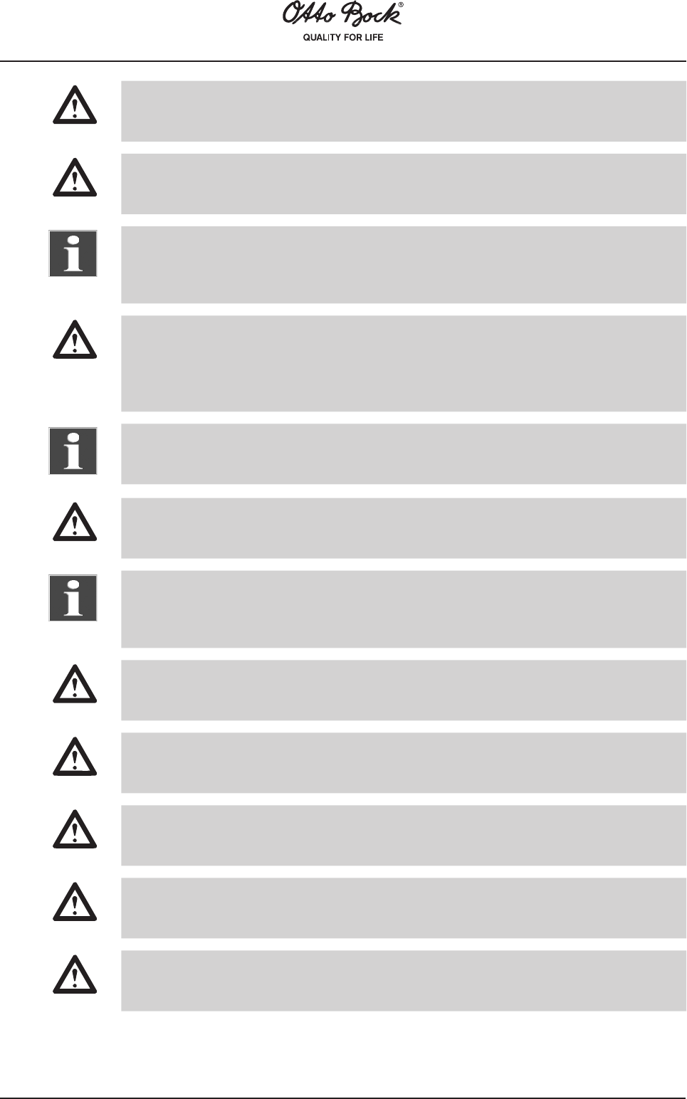
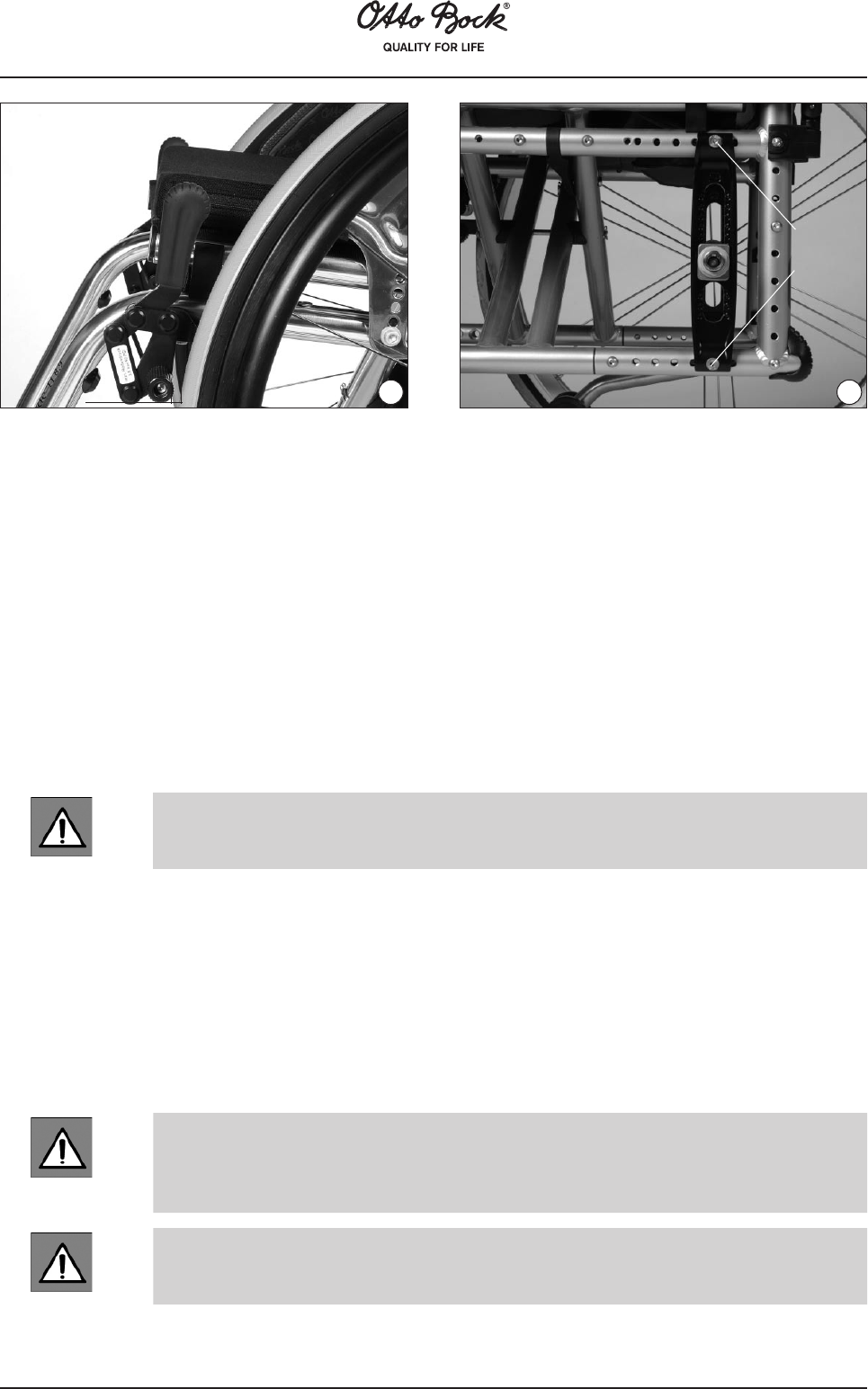
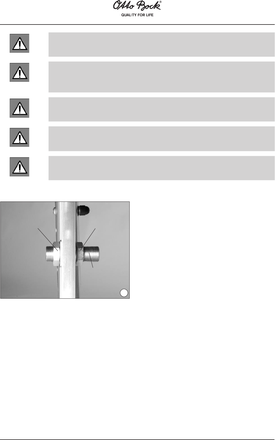
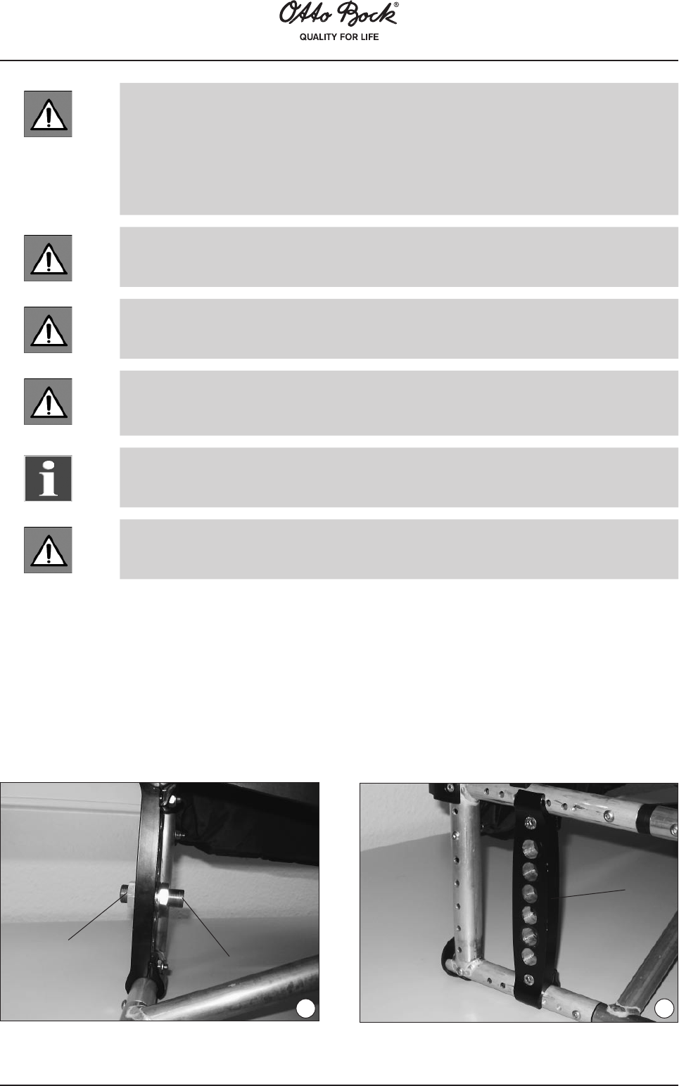
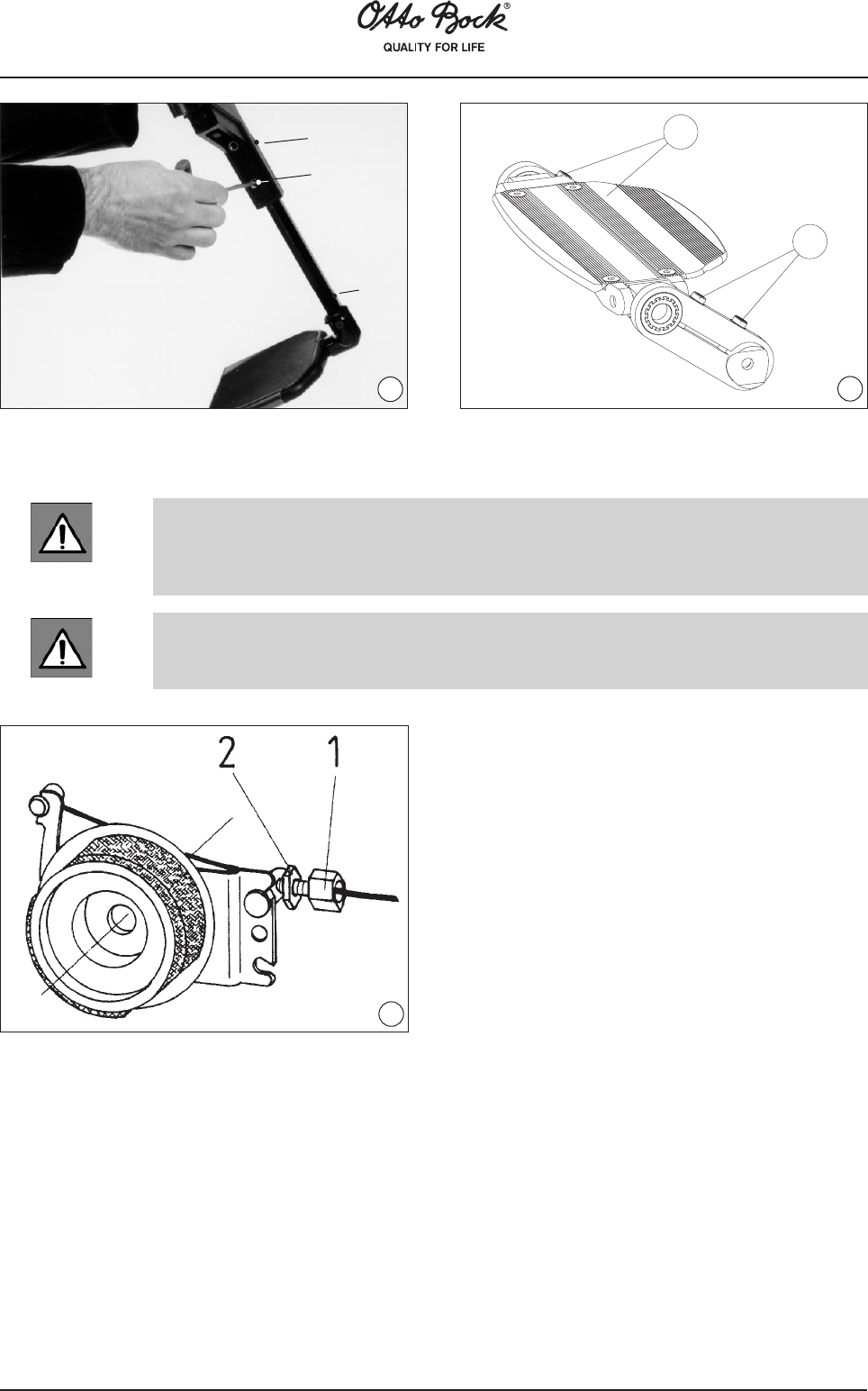
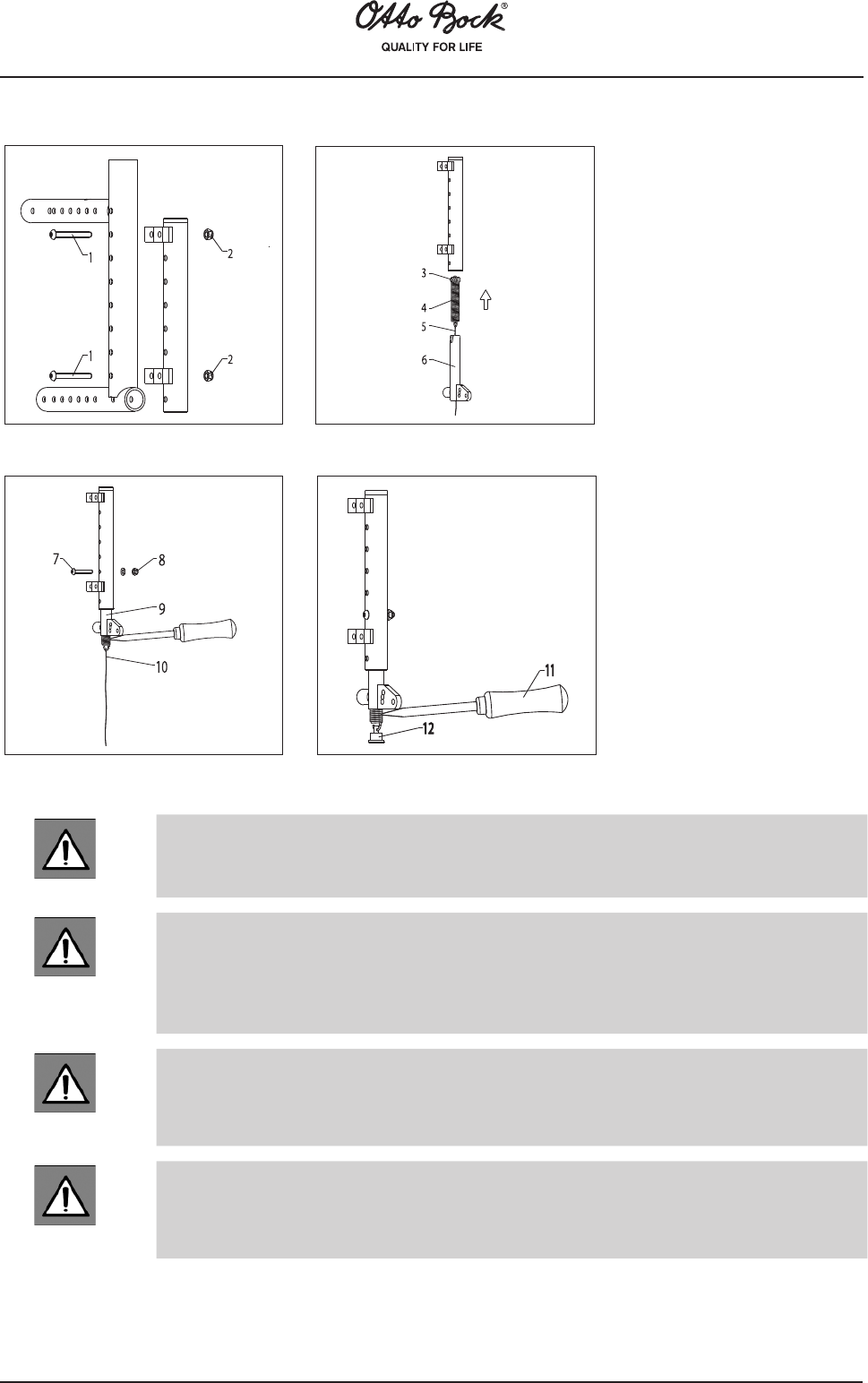
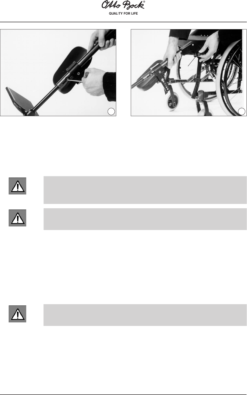
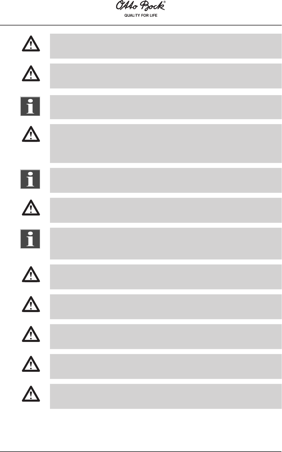
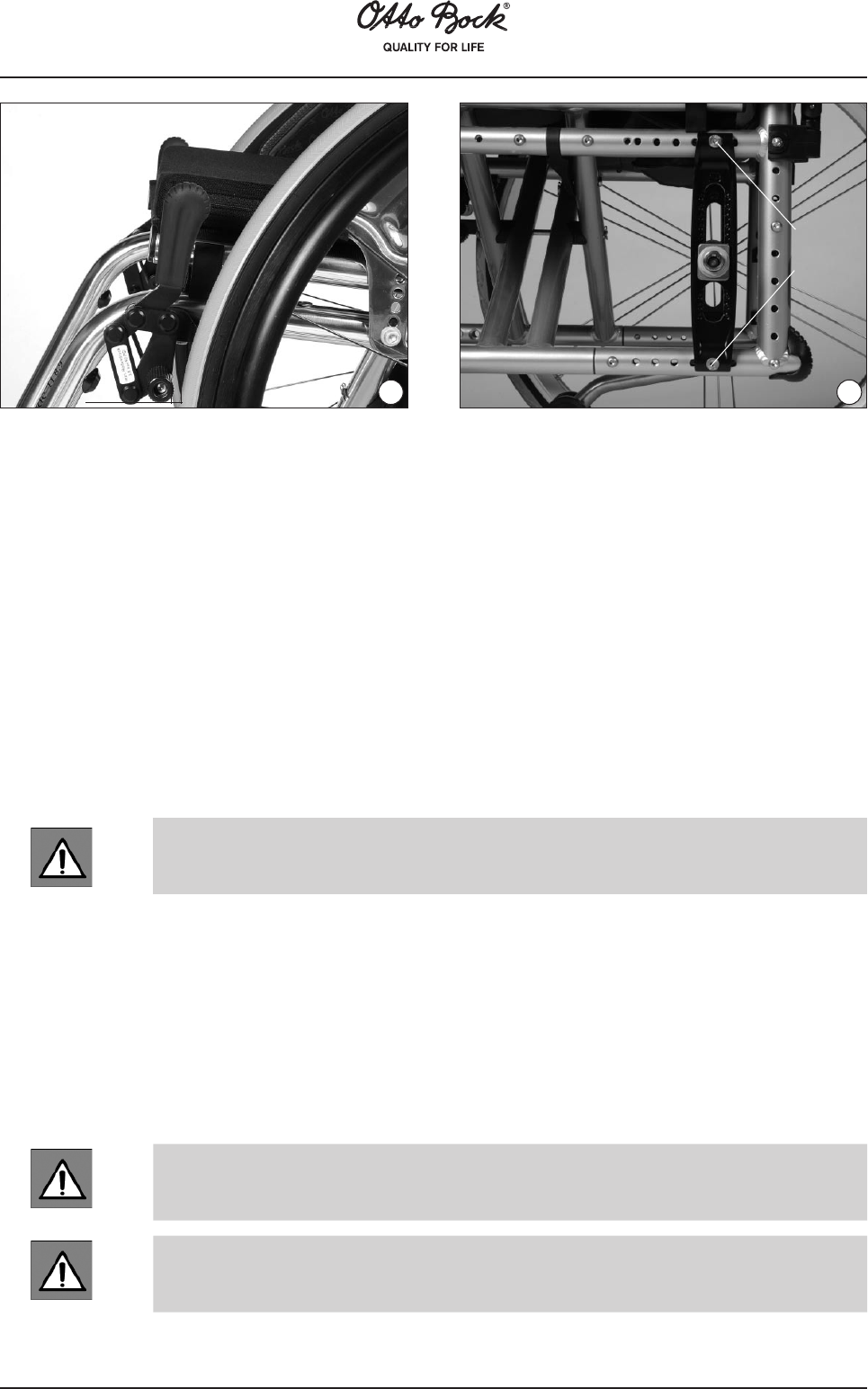
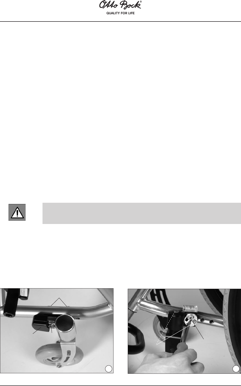
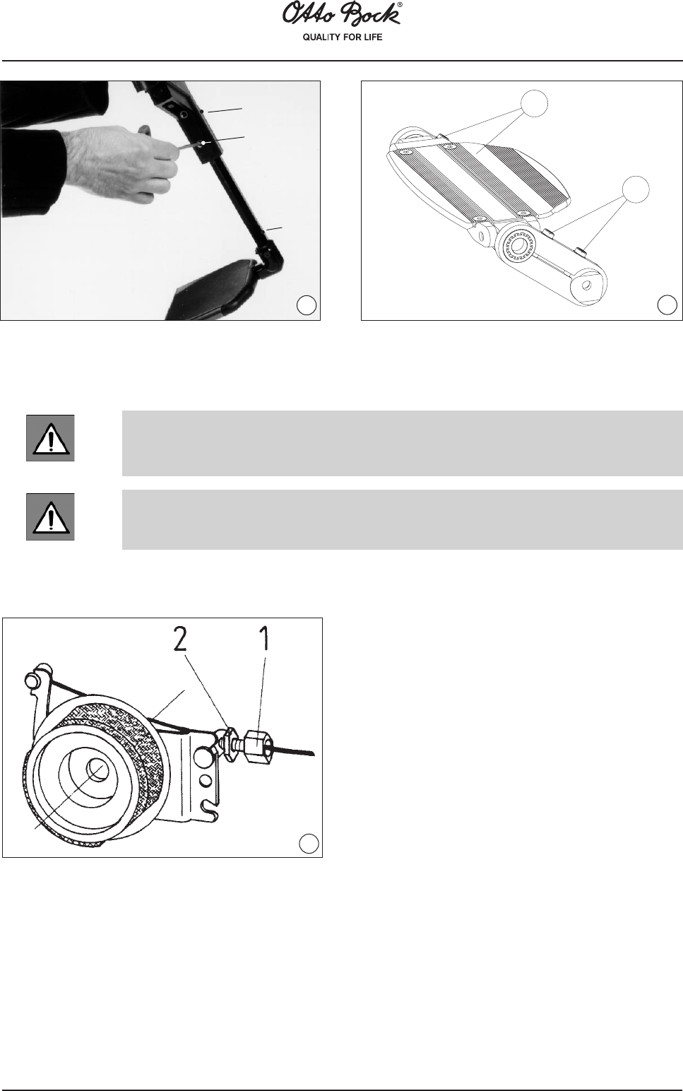
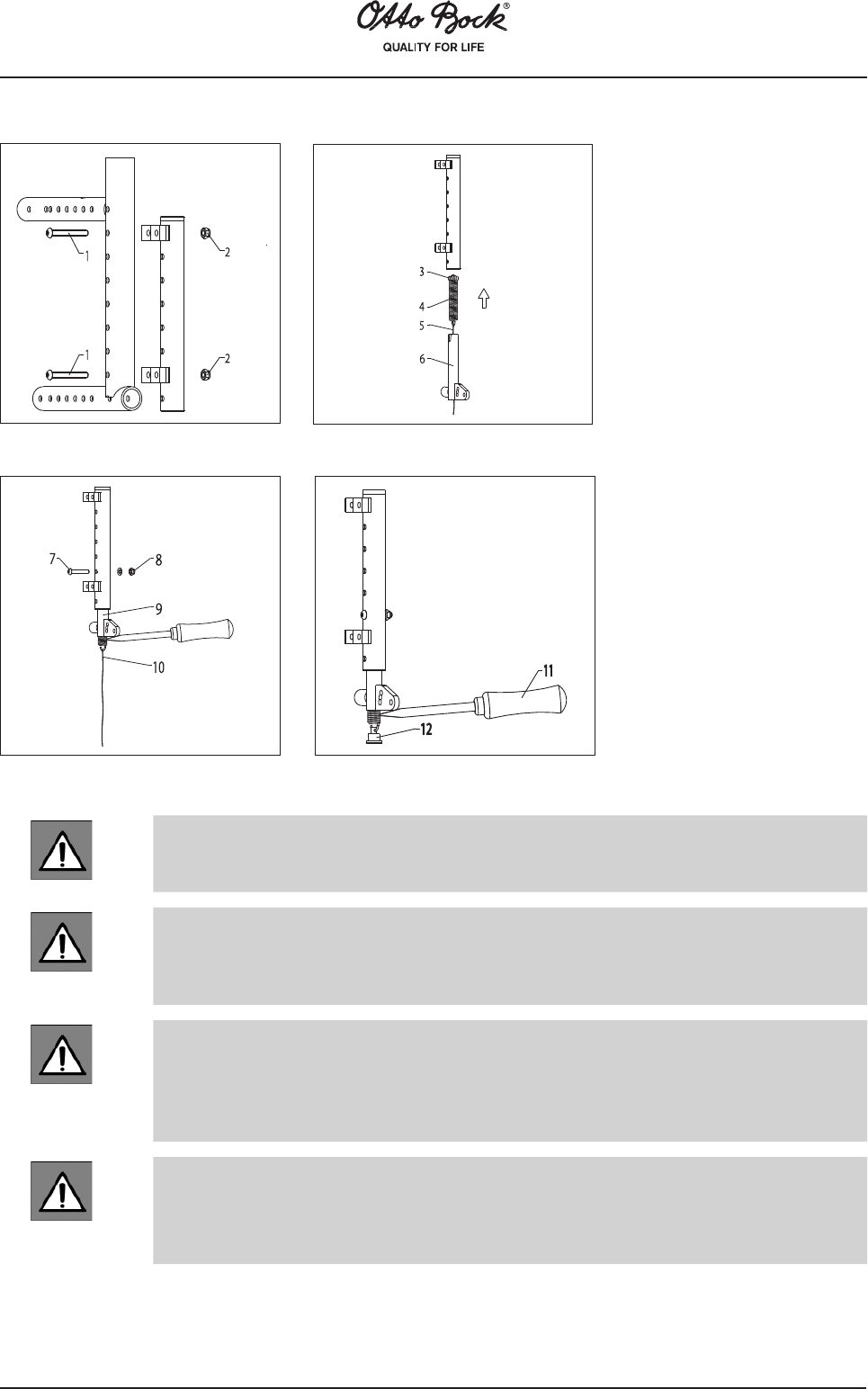
Mount the receiver tube with the two screws (Fig. 1, item 1) on the inner side of
the posterior frame part. Tighten the nuts (Fig. 1, item 2) with a torque of 9 Nm.
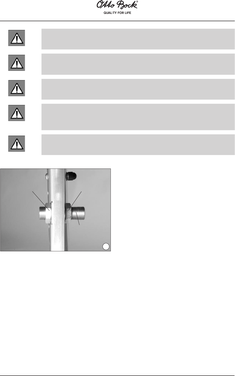
Insert the expansion spring (Fig. 2, item 4) with the close eyelet into the receiver
tube. When the receiver tube‘s bore hole and the eyelet hole are flush, insert the
sleeve (Fig. 2, item 3). Secure the sleeve with the screw (Fig. 3, item 7). Tighten
the nut (Fig. 3, item 8) with a torque of 7 Nm.
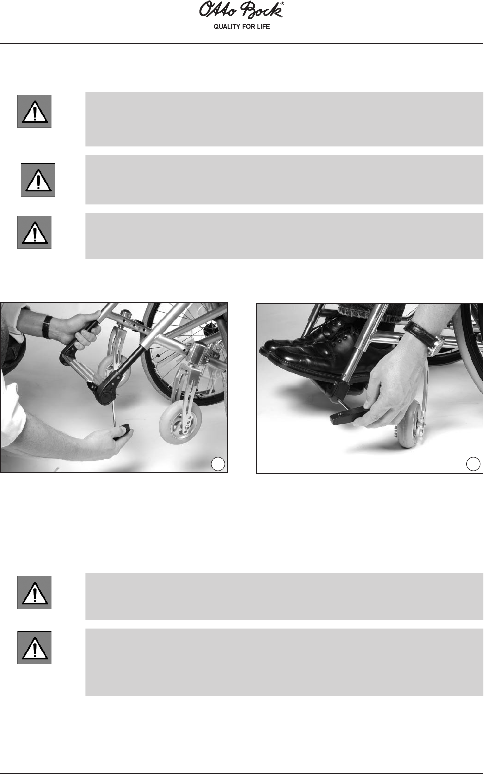
Hook a cord (Fig. 3, item 10) into the lower eyelet of the expansion spring and
push the anti-tipper tube (Fig. 2, item 6) over the cord and expansion spring into
the receiver tube.
Pull at the cord (Fig. 3, item 10) until the expansion spring extends from the anti-
tipper tube (Fig. 2, item 6).
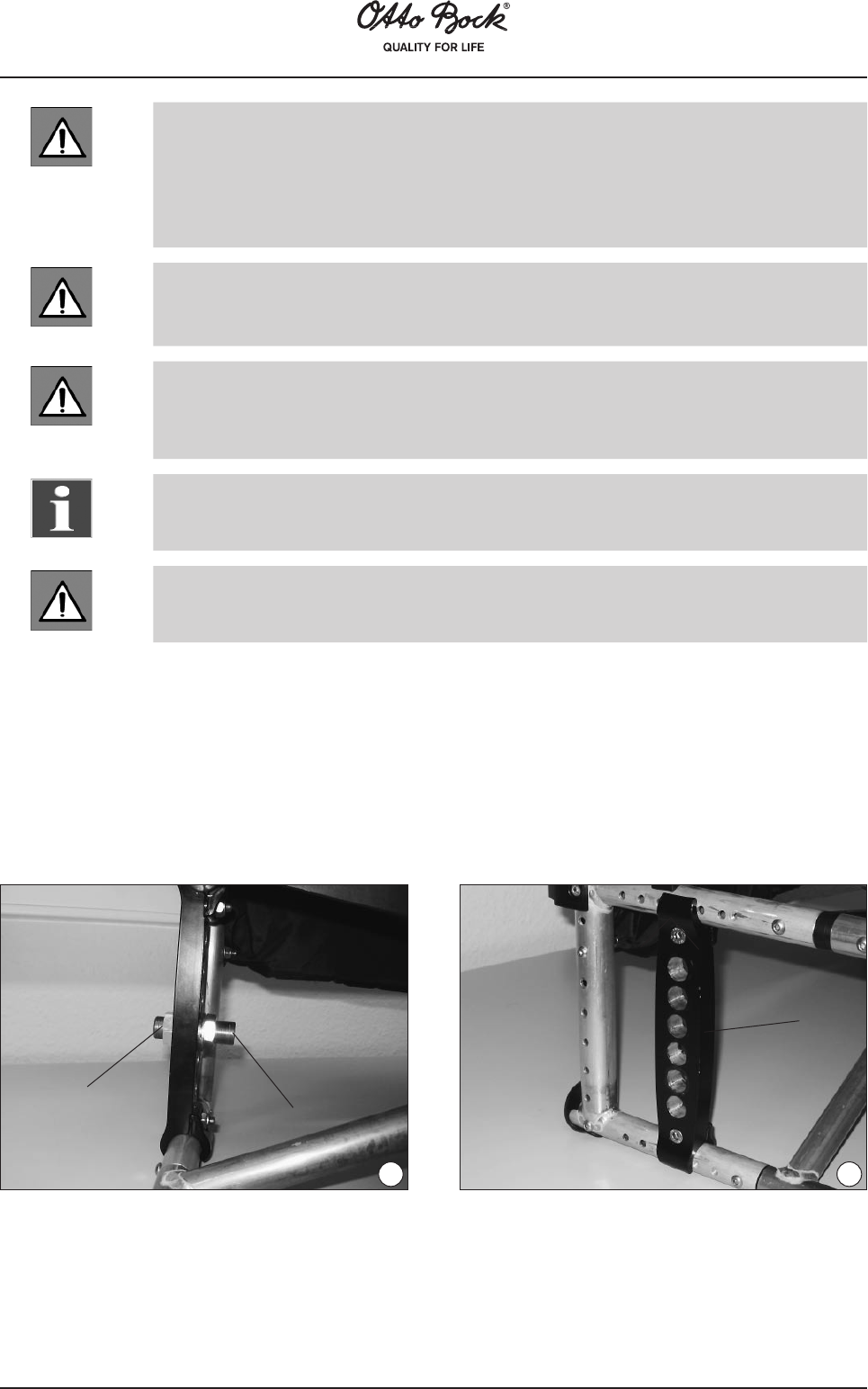
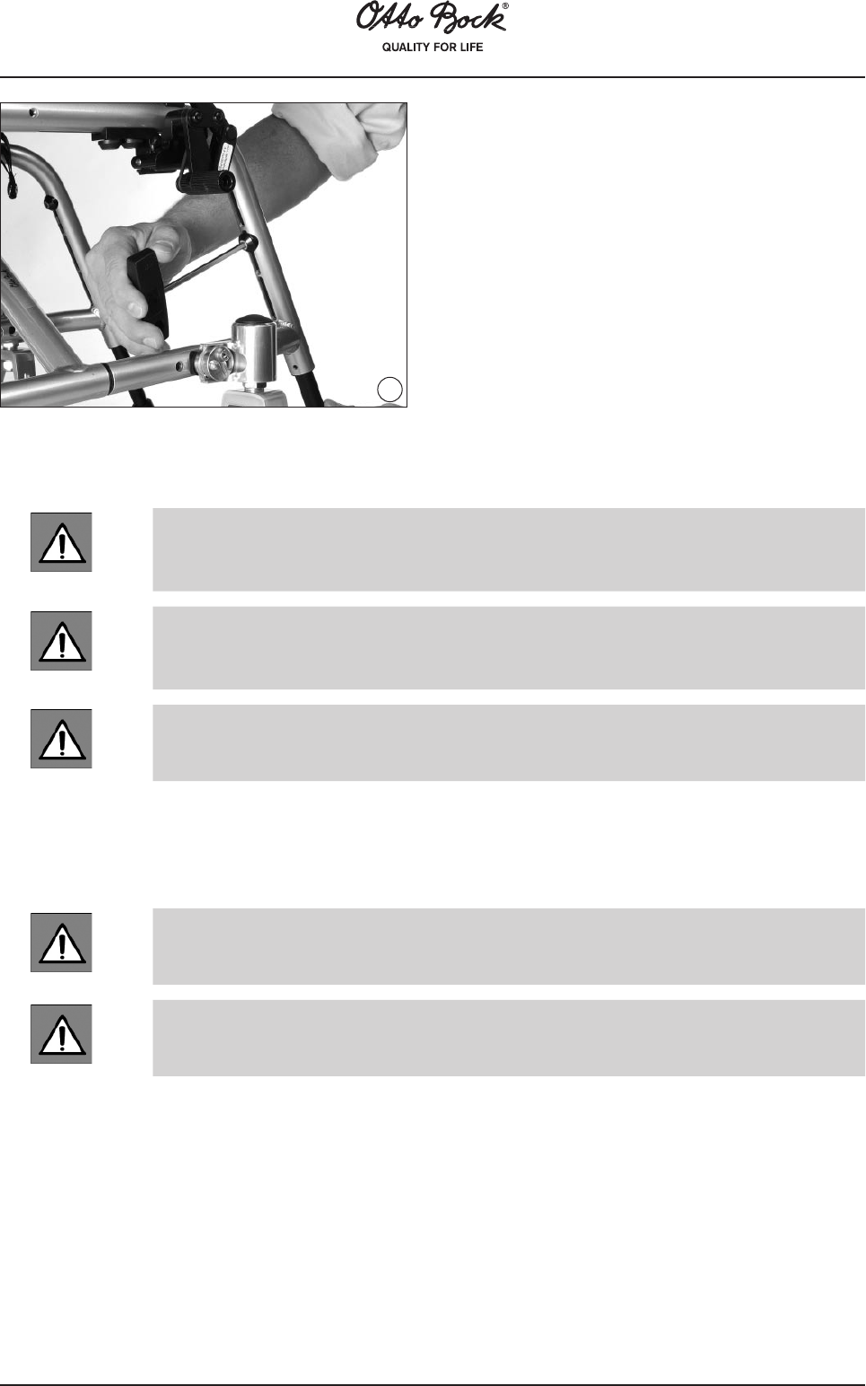
Secure the expansion spring using a screwdriver (Fig. 4, item 11) and remove the
cord. Put the spring holder (Fig. 4, item 12) onto the lower eyelet of the expansion
spring. Remove the screwdriver and the eyelet of the expansion spring will lock in
place.
Mounting the Anti-tipper
81
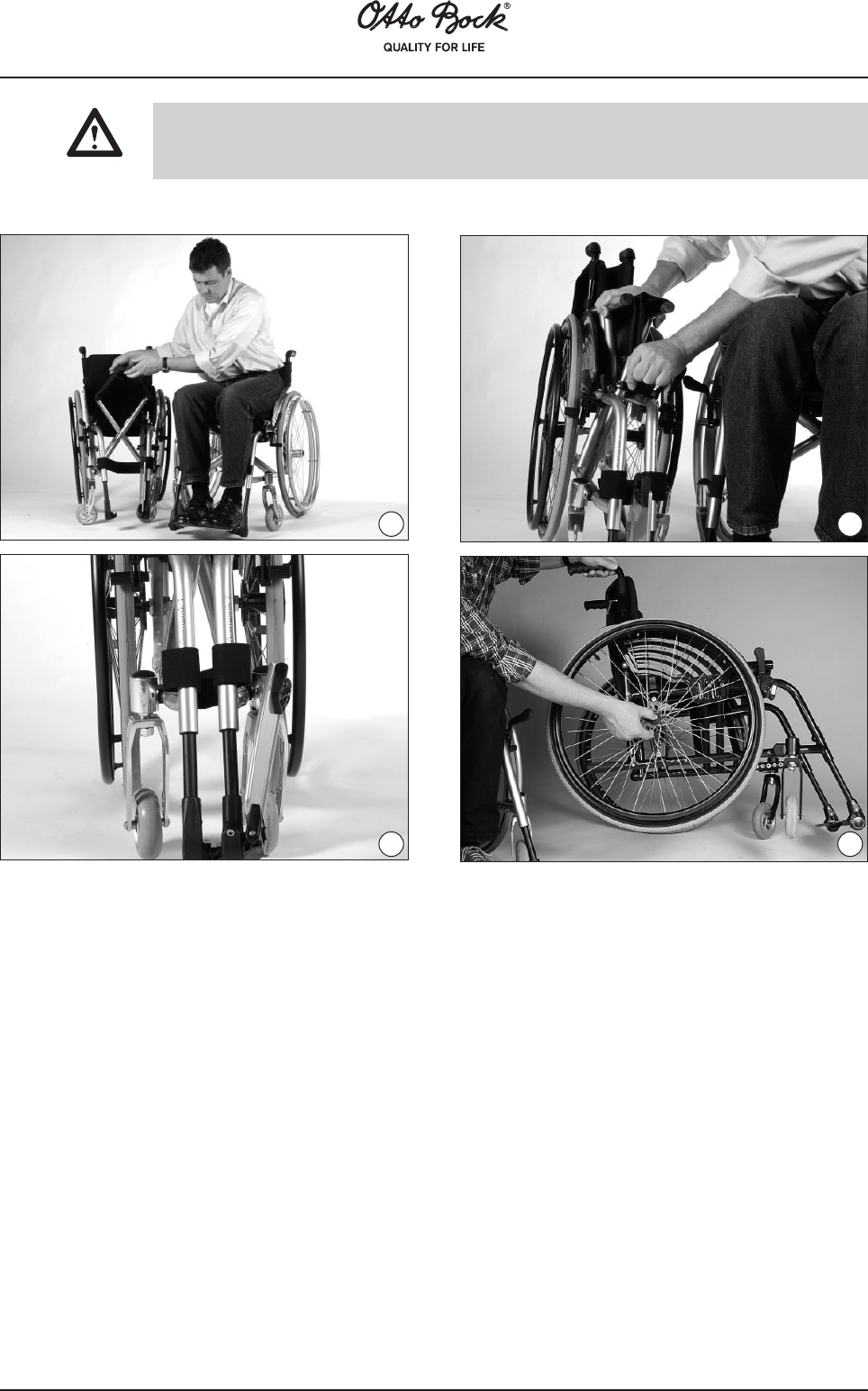
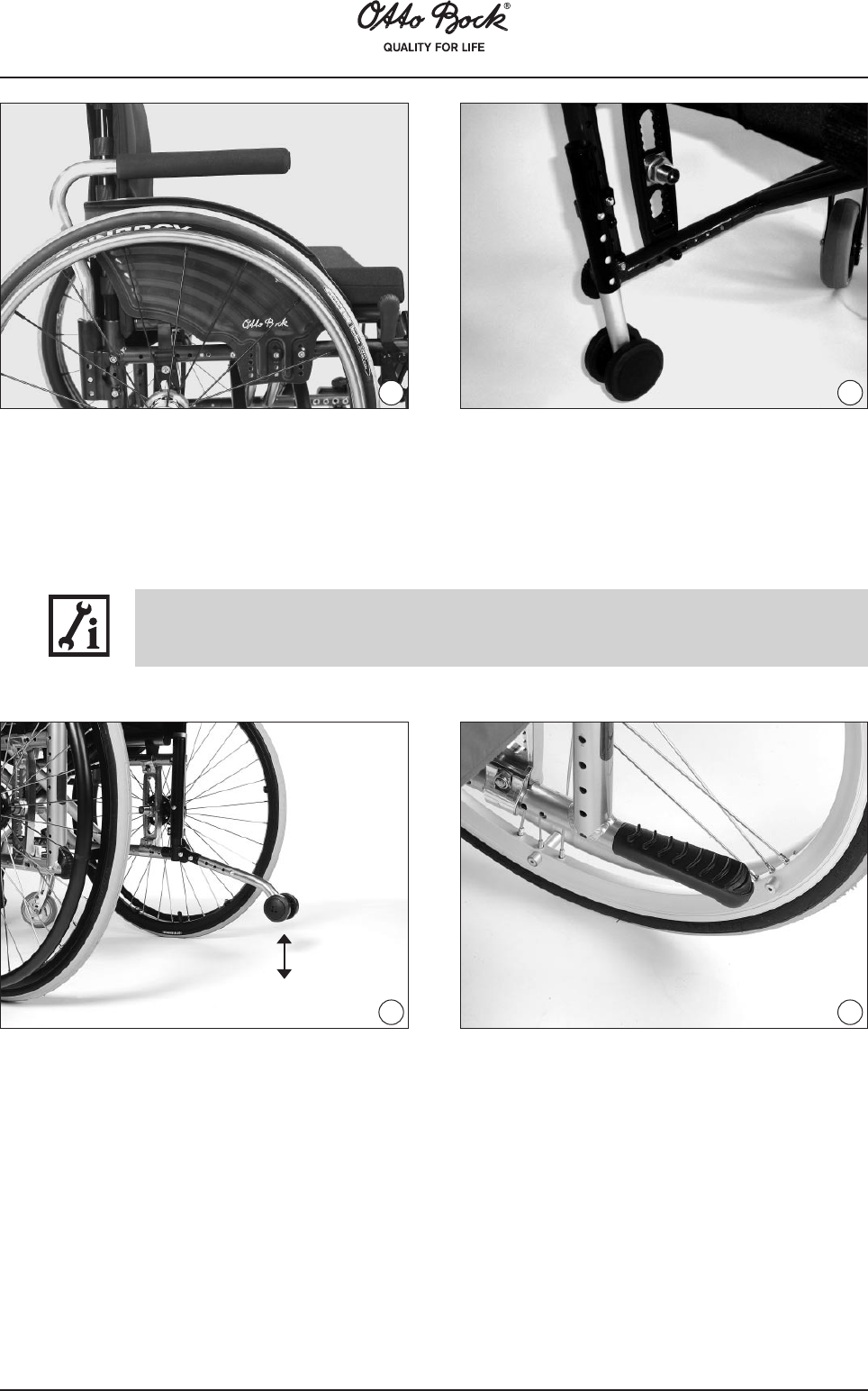
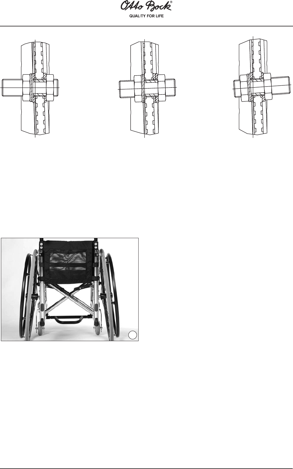
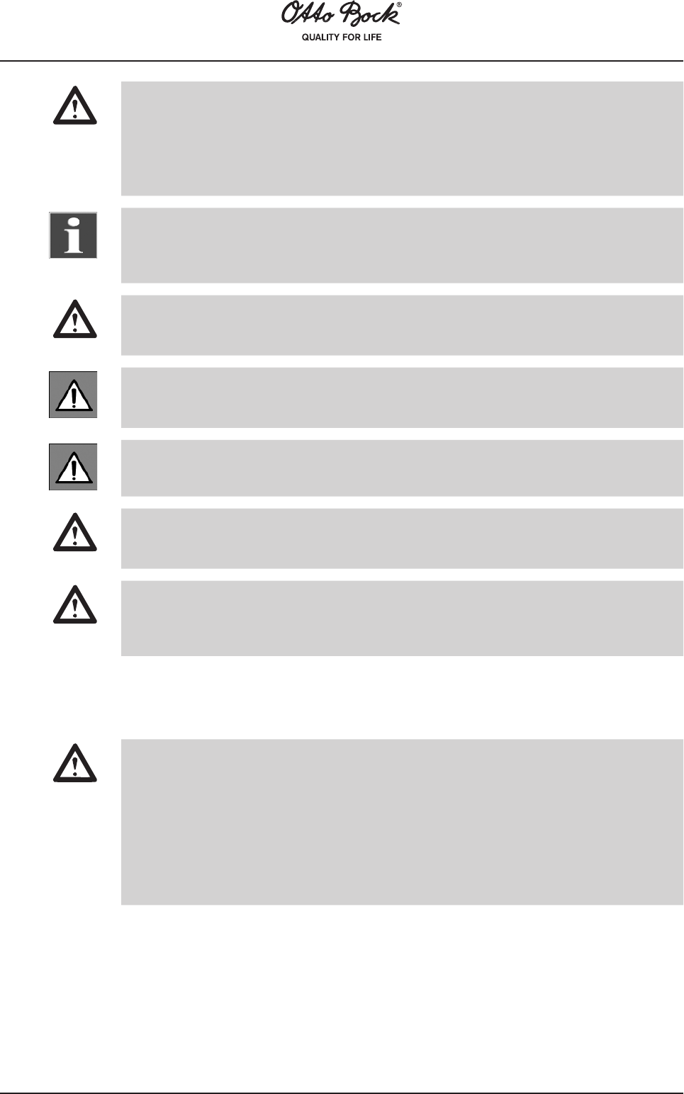
The anti-tipper can now be adjusted to the position of your rear wheel. After the screw connection
has been loosened, the anti-tipper can be horizontally and vertically adjusted.
The anti-tipper wheel must at least completely extend from the rear wheel to the back, and the
distance between the wheel and ground should not exceed 5 cm maximum (Fig. 13). Find the
appropriate position with the assistance of a helper!
Make sure to firmly retighten all screws and nuts after making adjustments.
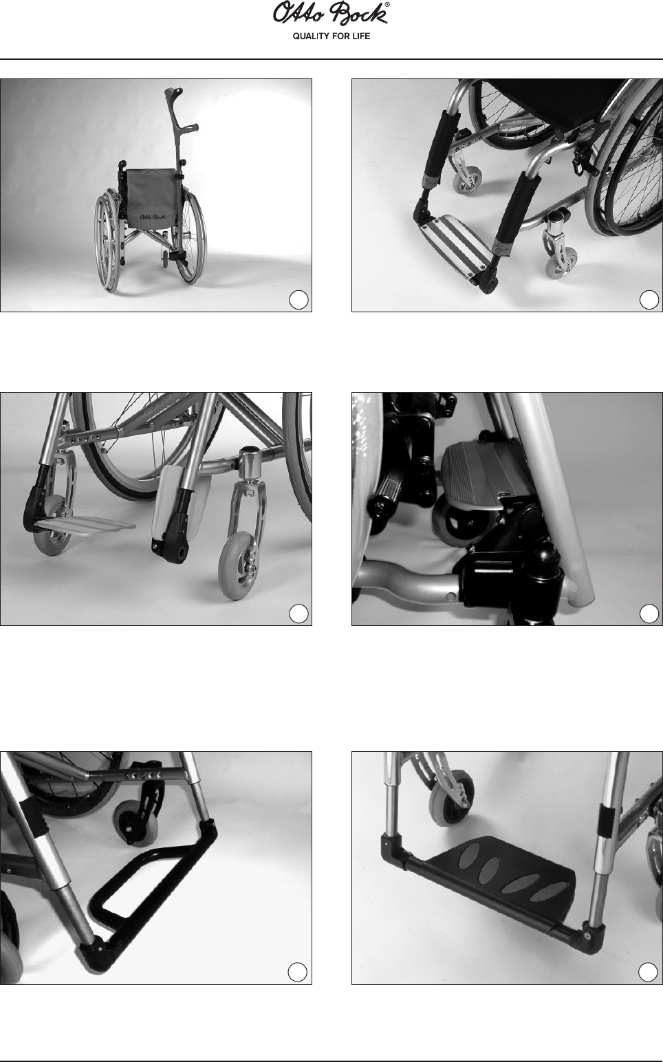
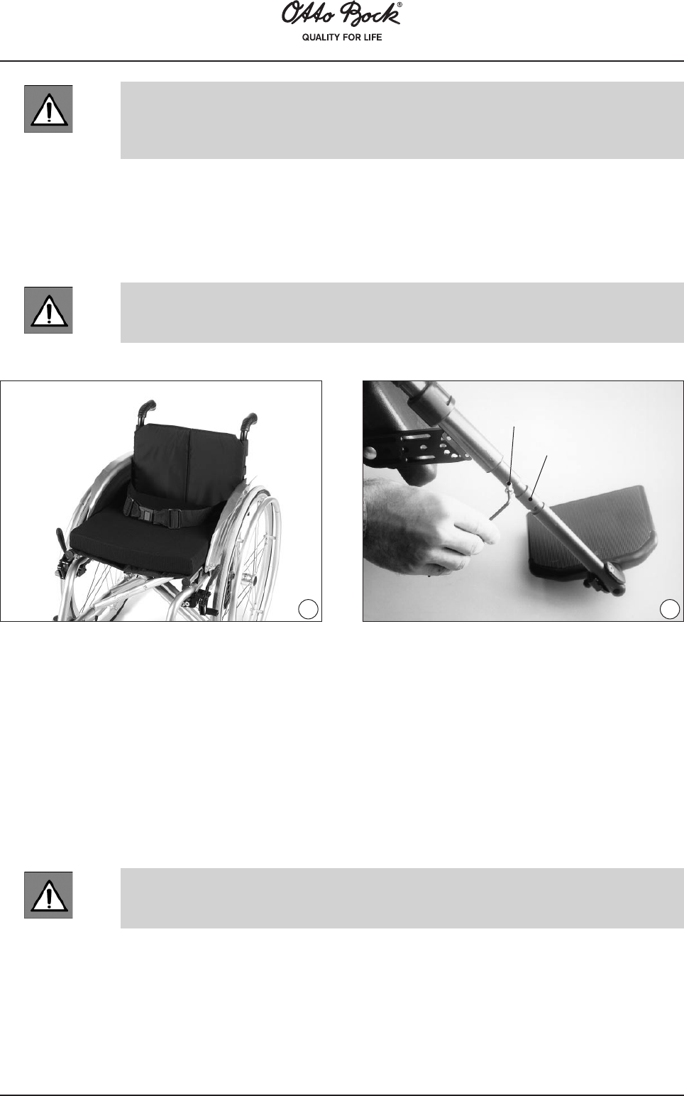
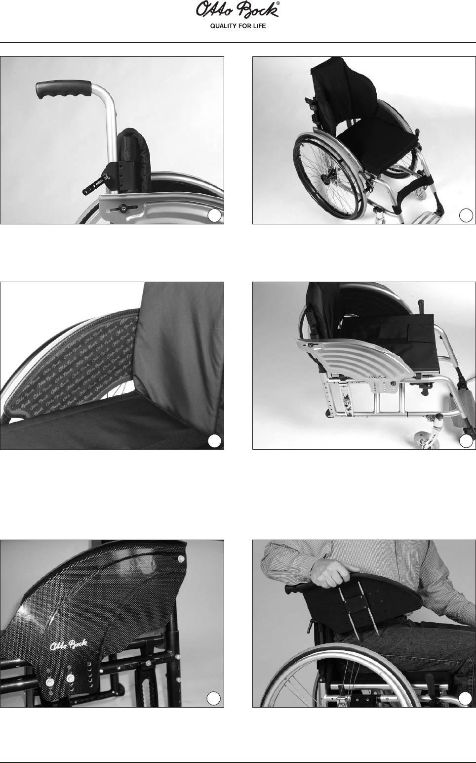
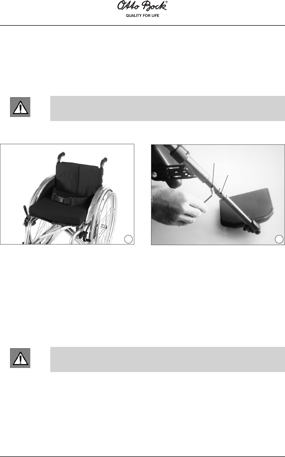
First remove the screw (Fig. 77, item a) from the footrest bar. To change the lower leg length,
you can now choose one of the upper or lower threaded holes in the footrest bar and screw
together the two components. Depending on the adjustment, it may be necessary to remove one
or several of the spacer sleeves (Fig. 77, item b).
Ensure to firmly re-tighten all screws and nuts after making adjustments.
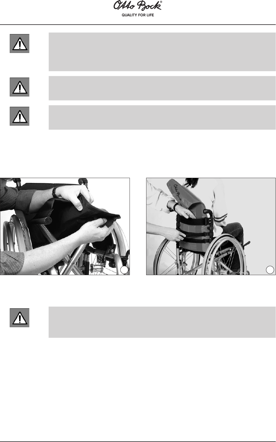
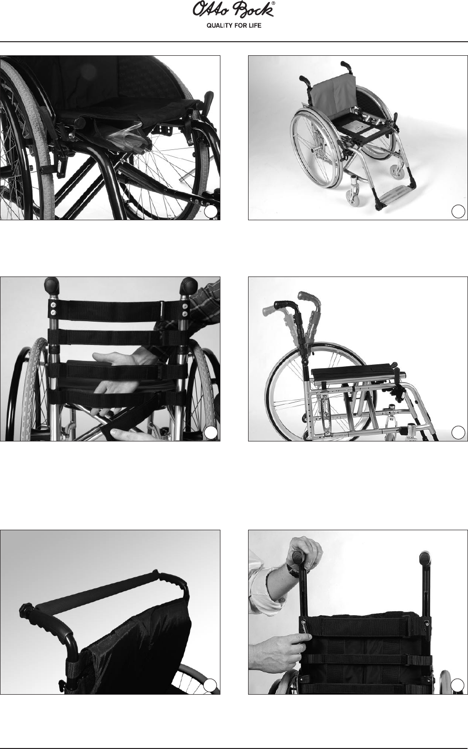
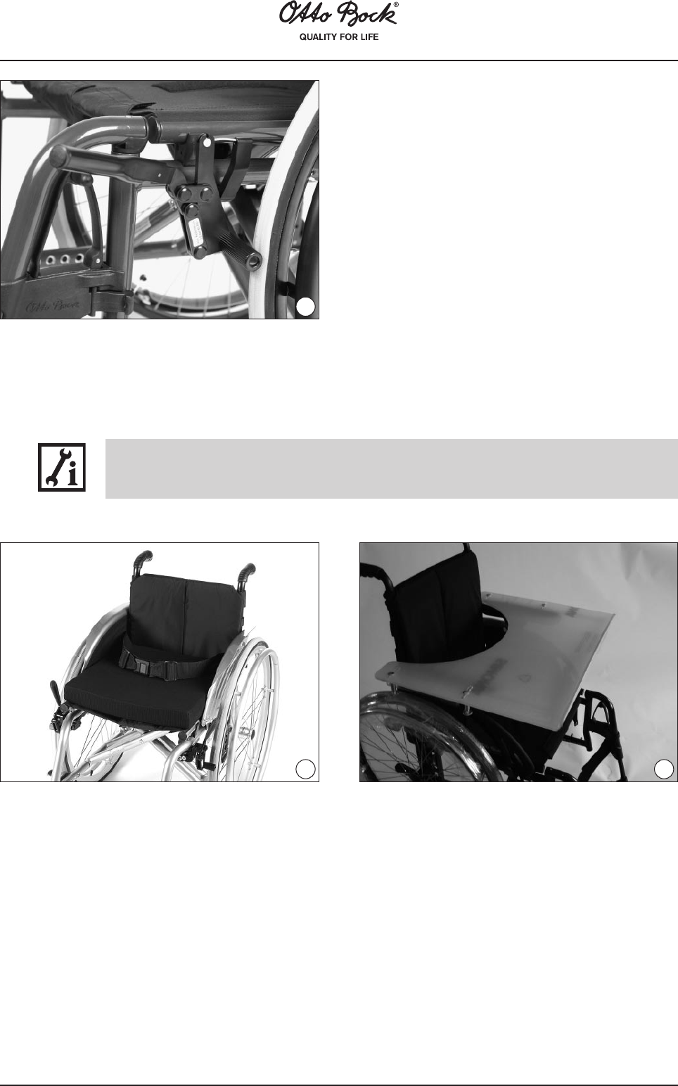
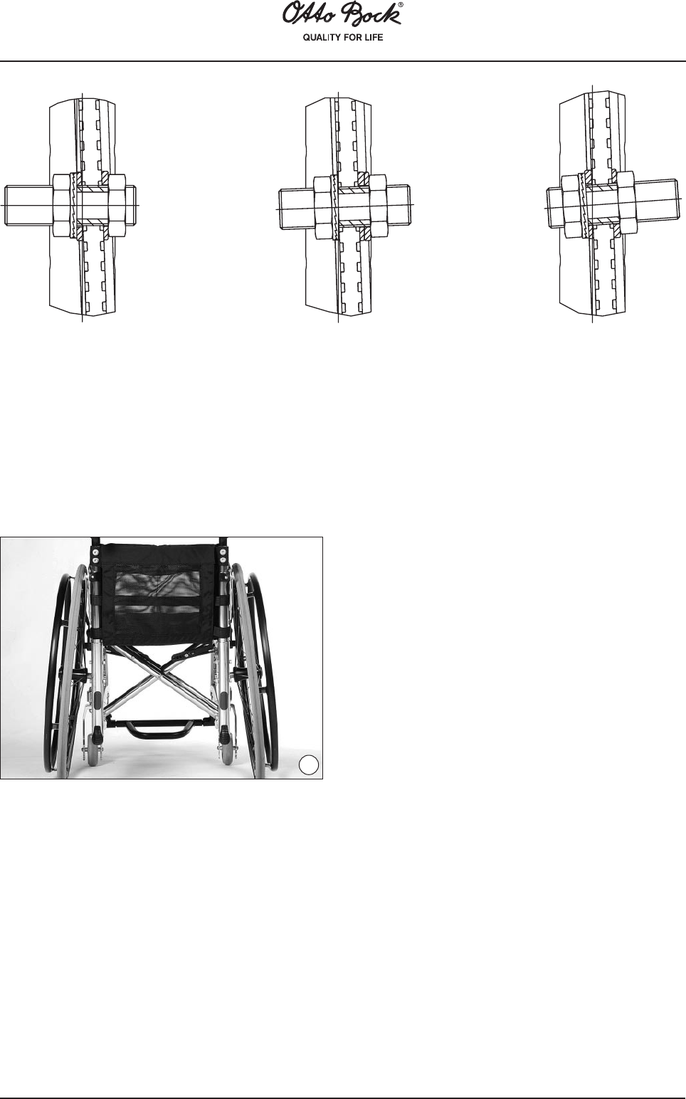
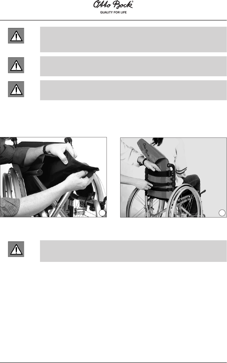
AttachingtheSafetyLapBeltThe attachment point
for the safety lap belt is in the upper most hole on
each side of the rear frame.
Height Adjustment of the Elevating Footrests
with Automatic Length Adjustment
a
b
7677
82
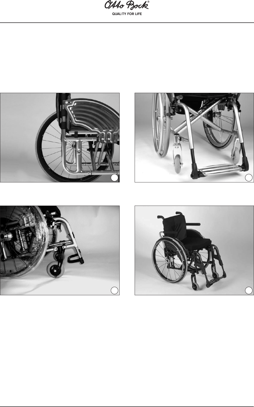
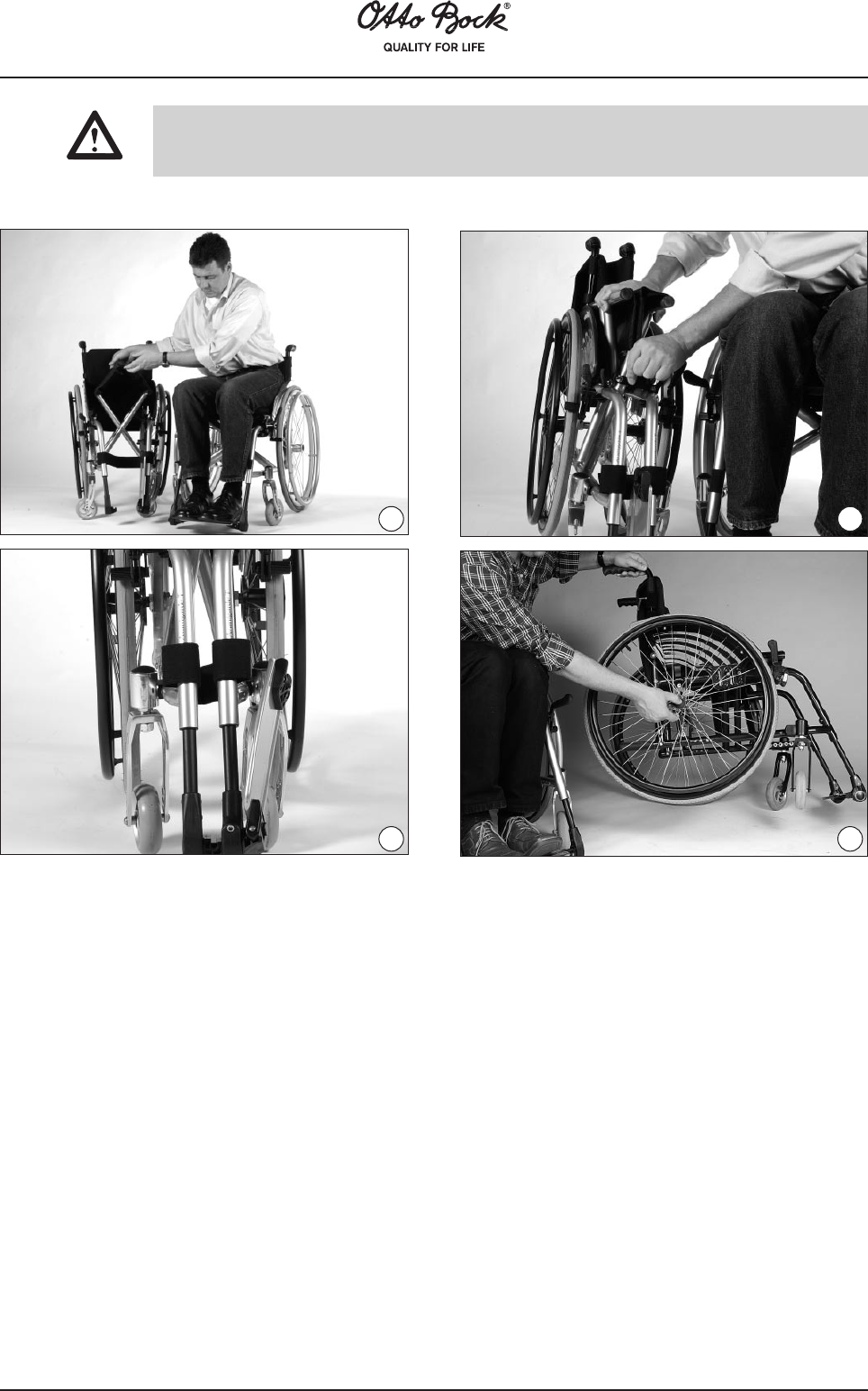
By loosening the screw at the footrest bar (Fig. 78), the footplate can be adjusted according to
your specific lower leg length and to the seat cushion you use.
There are five threaded holes in the footrest bar, it therefore may be necessary to
completely remove the screw and use another hole to achieve the desired footrest
height.
Ensure to firmly re-tighten all screws and nuts after making adjustments.
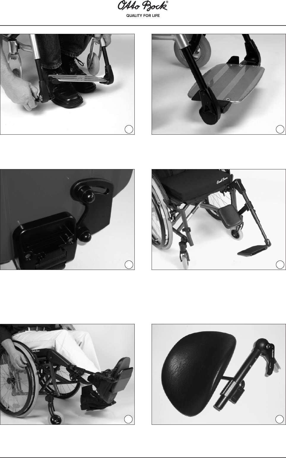
The legrests can be adjusted within the range from 15° to 90°. Pull the footrests upward until
they have reached the desired position. The legrests automatically lock in place. To reposition the
legrests relieve the load on the footrests and press the release lever (Fig. 79, item a) downward
to lower the legrests. Bring the legrests to the desired position.
Make sure to always secure the legrests with your hand against uncontrolled
falling downward when lowering it.
Height Adjustment of the Elevating Avantgarde
VR and XXL 2 Footrests
Angle Adjustment of the Elevating Avantgarde VR
and XXL 2 Footrests
7879
a
83
13 Maintenance, Cleaning, Care
Your Avantgarde wheelchair has been CE marked. The manufacturer herewith guarantees that
this medical product as a whole conforms to the requirements of the European Directive for
Medical Products 93/42/EEC.
On principle, the function of the wheelchair and especially of the brakes must be checked before
each use. Safety nuts should be used only once. If these nuts have been loosened several times,
they must be replaced. Should any defects become apparent, please contact your authorized
dealer immediately to eliminate them. This is particularly required, when you detect that the driving
behavior changes or that the wheelchair becomes unstable.
We also recommend that you have the wheelchair serviced every 12 months by your Otto Bock
approved dealer. The functions listed in the following table must be checked by the user at the
indicated intervals. Failure to carry out these simple checks may lead to problems arising that
could invalidate the warranty.
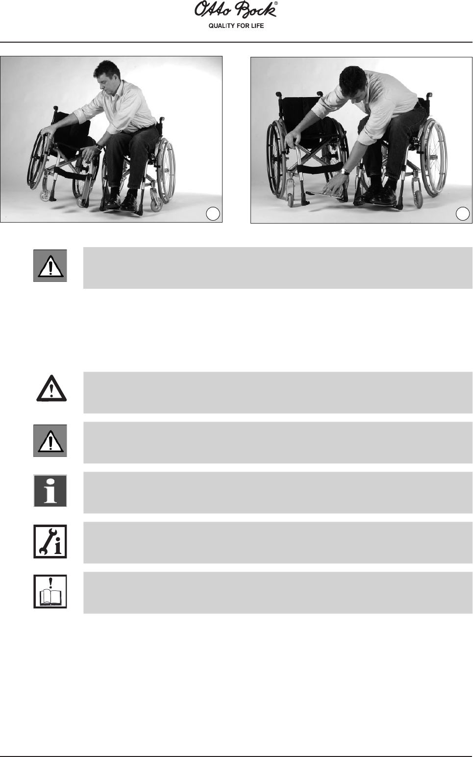
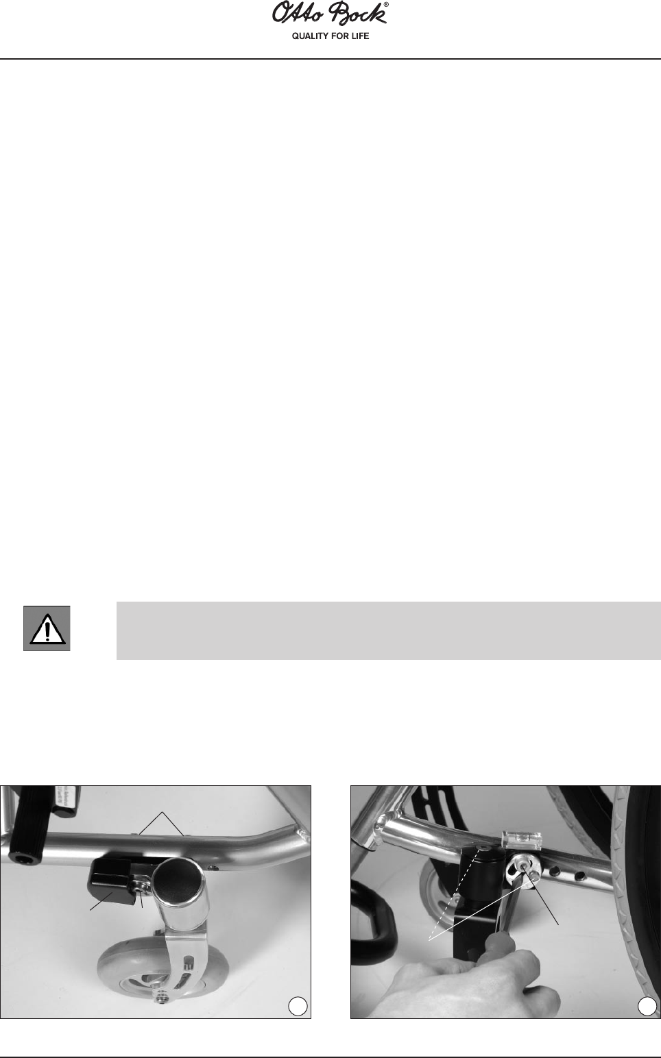
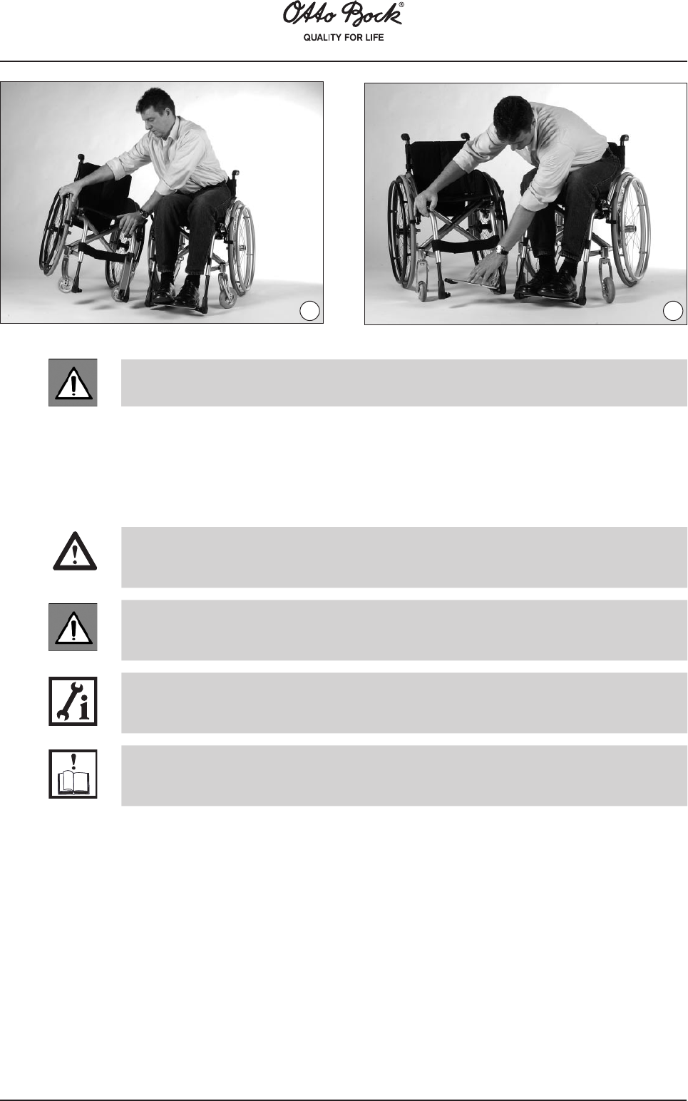
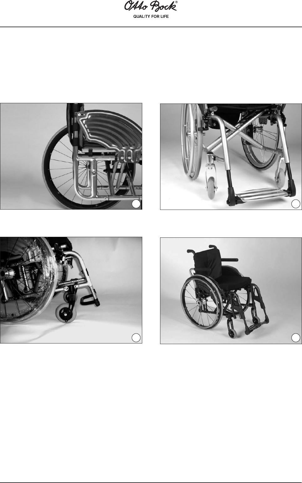
SwingingAwaytheElevatingAvantgardeFL
Footrests
Slightly lift the legrests and swing them
to the inside or outside
80
84
Check requiredBefore
starting
MonthlyQuarterly
Function test of the wheel locks/brakes
X
Sag of seat and back upholstery
X
Checking the setting of the caster journal
bearing
X
Visual examination of wearing parts (e.g. tires,
bearings)
X
Contamination on bearings
X
Push rings for damages
X
Air pressure (printed on the sidewall of the tire)
X
Folding mechanism for wear
X
Checking the spoke tension of the rear wheels
X
Checking the screw connections
X
Should any defects become obvious, please contact your authorized dealer to rectify them.
We also recommend you to have your wheelchair serviced by your authorized dealer every three
months.
Cleaning
To clean your wheelchair, use a mild detergent and a soft cloth.
Certain components can be easily maintained by yourself so as to ensure smooth operation of
your wheelchair:
• Hair and/or dirt particles may accumulate between the caster wheel and fork, this can
restrict the caster wheels from rotating smoothly. Thoroughly clean between the fork and
caster wheels/axle using a soft cloth and if required a mild detergent.
• The rear wheels and caster wheels can be supplied as a quick-release axle system.
To keep this system operational, ensure no dirt/grit adheres to the quick-release axle or
axle housing. Lightly lubricate the quick-release axle regularly with resin-free sewing
machine oil.
• If your wheelchair gets wet, towel dry it as soon as possible.
• Do not use your wheelchair in salt water, as sand, salt and/or other particles will cause
corrosion and cause damage to wheel bearings.
• Check the tightness of all screw connections regularly. If any screw connection persists in
becoming loose, consult your authorized dealer immediately!
85
14 Changing Tires
We recommend that you always carry an air pump and tire repair kit for emergencies. As an
alternative, consider keeping a spray can of hardening foam (available from local bicycle shops)
to fill your tire in case of punctures.
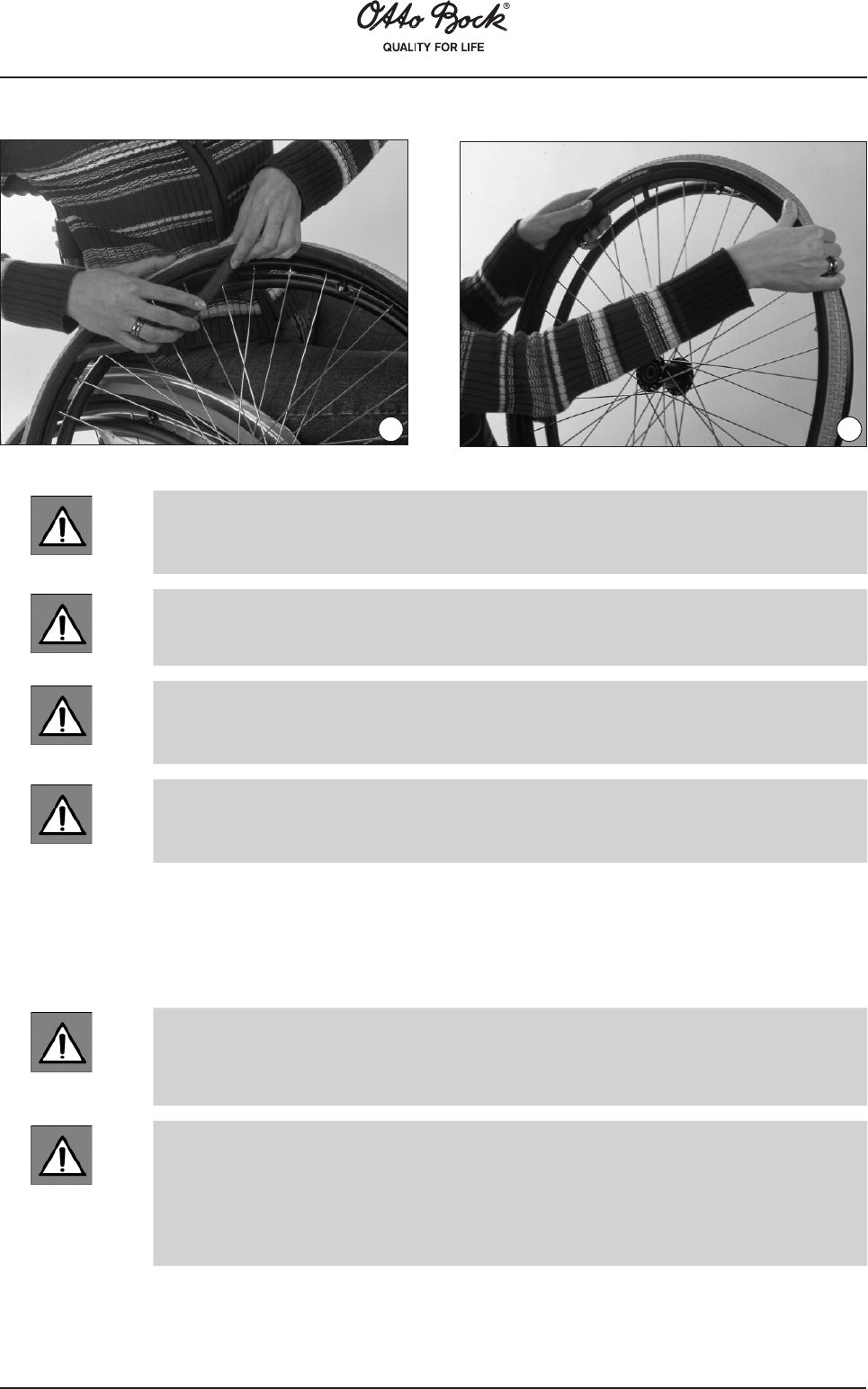
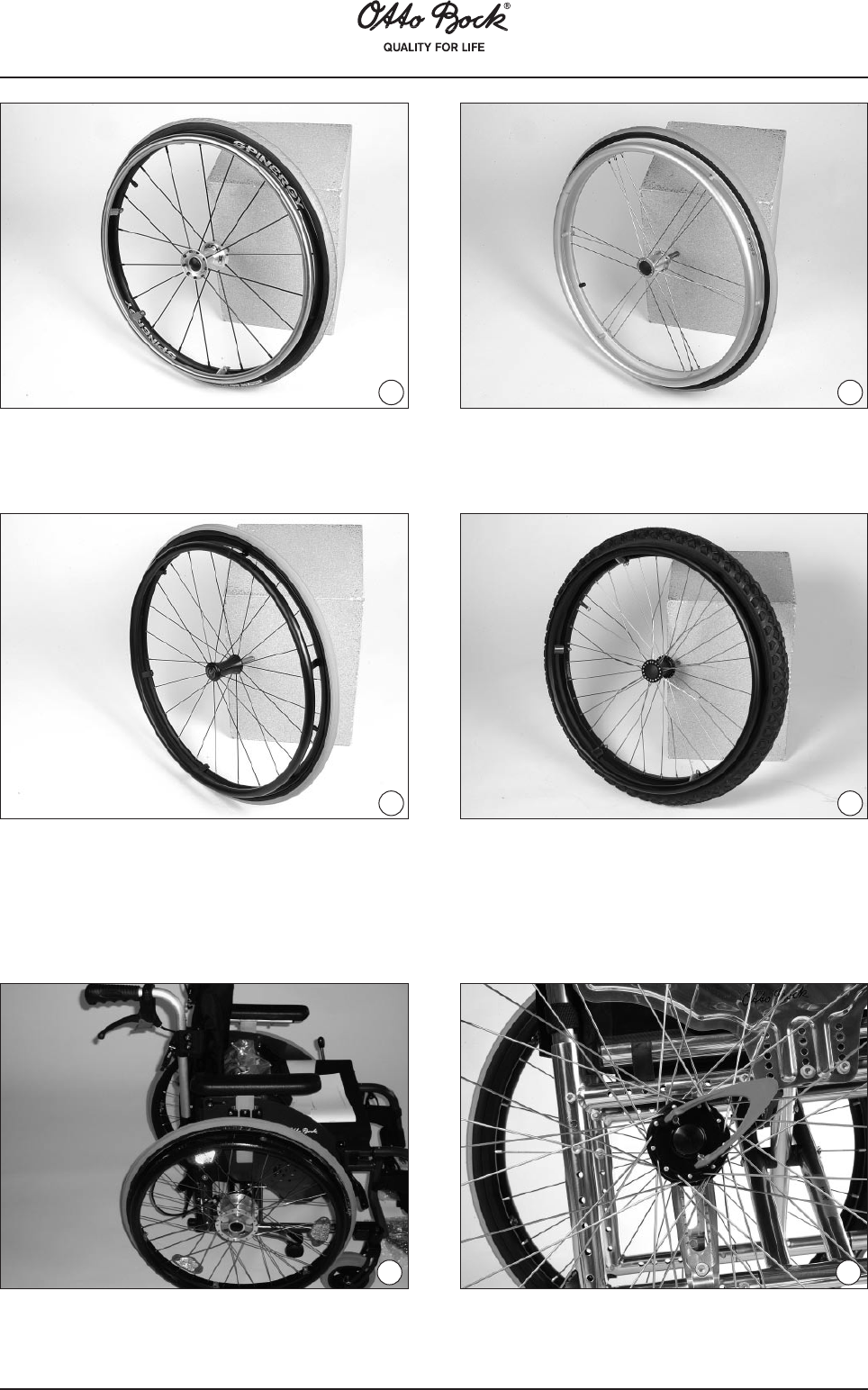
If a tire becomes flat, use the appropriate tools to carefully remove the tire from the
rim.
Ensure you do not damage the rim and/or the inner tube.
86
Repair the inner tube according to the directions in the repair kit, or replace the
old inner tube with a new one.
Before re-mounting the tire inspect the inner rim surface of the wheel and the
inside of the tire for any object that may have caused the puncture.
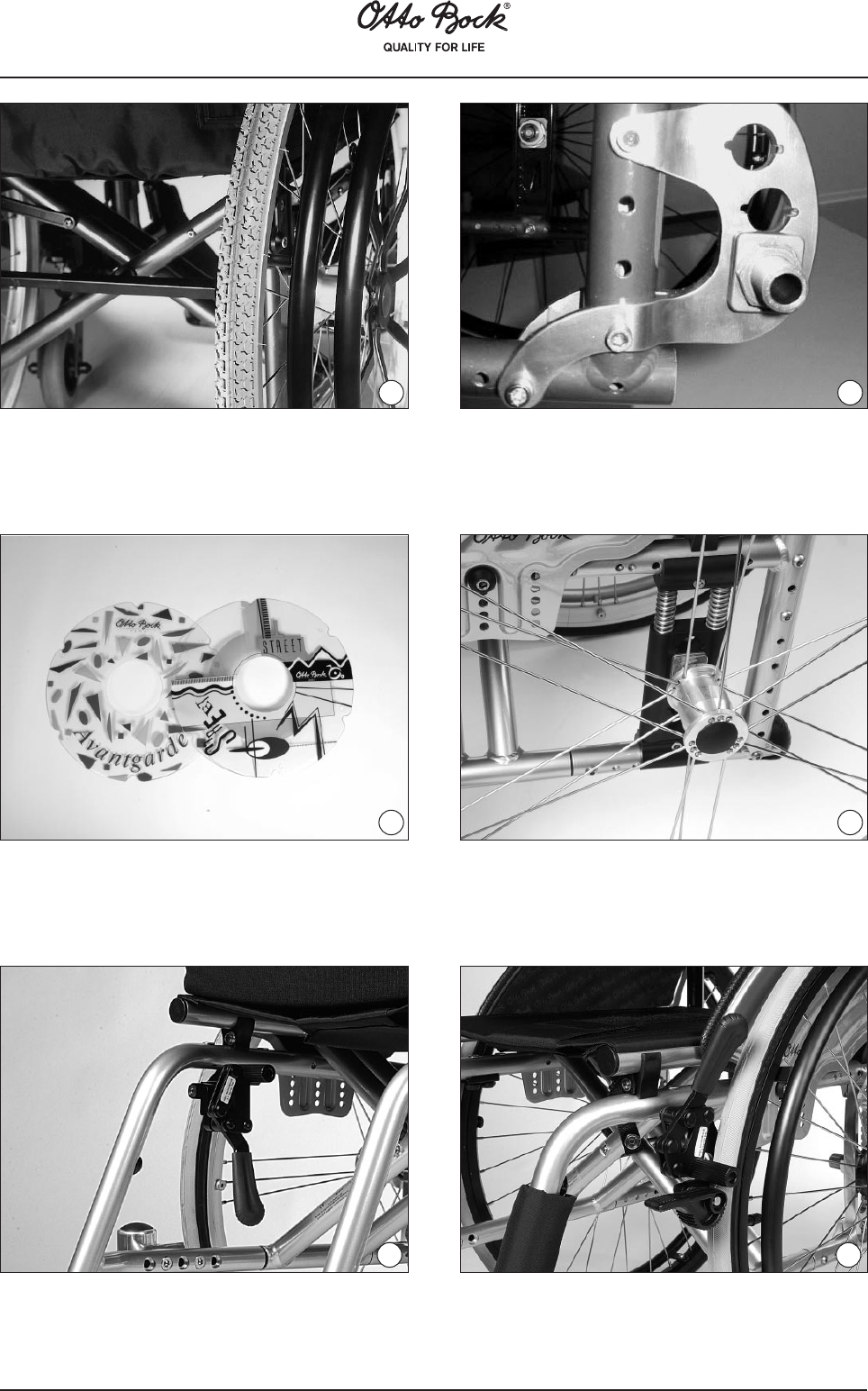
Ensure the rim bands are not damaged, as they protect the inner tube from being
damaged by the ends of the spokes.
Remove dust cap and place the protective rim band over the valve of the inner
tube, and insert the valve through the rim. Lightly screw on the valve nut if there
is one. Now fit the rim band centrally around the wheel rim, ensuring that all the
spoke ends are covered.
Insert the wall of the tire over the edge of the wheel rim adjacent to the valve (hint:
lightly push up the valve to assist tire fitting and prevent inner tube from being
pinched between tire and wheel rim). Inflate the inner tube with a small amount of
air and continue to insert the inner tube into the tire.
Check the inner tube for folds. If folds are present, release some air. Now working
away from the valve, work the tire wall over the wheel rim until it is fully fitted onto
the wheel.
8182
Mounting Tires
87
Inating
Check both sides of the wheel to ensure that the tire is seated correctly and fully on the rim.
Push the valve back up slightly into the tire then pull it out again so the tire is well-seated in the
valve area.
Inflate the tire with enough air so that it can be pressed in easily with your thumb. Ensure the tire
is centered on the rim before continuing. If not, let some air out and realign the tire. Inflate the
tire to the pressure indicated on the side wall, then re-fit and tighten the dust cap.
88
15 Technical Data
Overall length (in cm) Avantgarde T, Ti 8.9, Ti Ultra and VR
Model Avantgarde T und Ti 8.9 and Ti Ultra
Rear wheel size
22”24”MTB 24”26”
Seat depth
Rear axle
position
Front axle
position
Rear axle
position
Front axle
position
Rear axle
position
Front axle
position
Rear axle
position
Front axle
position
36 - 428980,591,58392,5849485,5
44 - 469384,595,58796,5889889,5
Model Avantgarde VR
Seat depth
Low.leg
length max./
min.
22”24”MTB 24”26”
Rear axle
position
Front axle
position
Rear axle
position
Front axle
position
Rear axle
position
Front axle
position
Rear axle
position
Front axle
position
36
55
32
89
83
80,5
74,5
91,5
85,5
83
77
92,5
86,5
84
78
94
88
85,5
79,5
38
55
32
91
85
82,5
76,5
93,5
87,5
85
79
94,5
88,5
86
80
96
90
87,5
81,5
40
55
32
93
87
84,5
78,5
95,5
89,5
87
81
96,5
90,5
88
82
98
92
89,5
83,5
42
55
32
95
89
86,5
80,5
97,5
91,5
89
83
98,5
92,5
90
84
100
94
91,5
85,5
44
55
32
97
91
88,5
82,5
99,5
93,5
91
85
100,5
94,5
92
86
102
96
93,5
87,5
46
55
32
99
93
90,5
84,5
101,5
95,5
93
87
102,5
96,5
94
88
104
98
95,5
89,5
48
55
32
101
95
92,5
86,5
103,5
97,5
95
89
104,5
98,5
96
90
106
100
97,5
91,5
50
55
32
103
97
94,5
88,5
105,5
99,5
97
91
106,5
100,5
98
92
108
102
99,5
93,5
Overall width (in cm)
1)
Avantgarde T, Ti 8.9, Ti Ultra and VR
Seat widthStandard side panels
& clothing protectors
Side panel with amrest
height adjustable
Rear wheel with
drum brake
3248,55152
3450,5
5354
3652,5
5556
3854,55758
4056,55960
4258,56162
4460,56364
4662,56566
4864,56768
5066,5
6970
1)
Indications apply to push ring attachment narrow and rear wheel camber of 0° (with push ring attachment wide: Add 20 mm).
89
Technical Data
Overall length (in cm) Avantgarde XXL 2
Seat depthLow.leg lengthmax./min.
24”26"
Rear axle positionFront axle positionRear axle positionFront axle position
40
55
32
95,5
89,5
85
79
98
92
87,5
81,5
42
55
32
97,5
91,5
87
81
100
94
89,5
83,5
44
55
32
99,5
93,5
89
83
102
96
91,5
85,5
46
55
32
101,5
97,5
91
85
104
98
93,5
87,5
48
55
32
103,5
97,5
93
87
106
100
95,5
89,5
50
55
32
105,5
99,5
95
89
108
102
97,5
91,5
52
55
32
107,5
101,5
97
91
110
104
99,5
93,5
54
55
32
109,5
103,5
99
93
112
106
101,5
95,5
56
55
32
111,5
105,5
101
95
114
108
103,5
97,5
Overall width (in cm) Avantgarde XXL 2
Seat widthStandard side panels &
clothing protectors
Side panel with armrest,
height adjustable
Rear wheel with drum
brake
5069,5
7273
5271,5
7475
5473,5
7677
5675,5
7879
5877,5
8081
6079,58283
6281,58485
1)
Indications apply to push ring attachment narrow (with push ring attachment wide: +20 mm).
Some of the models shown here feature special equipments for additional charge. The indications regarding scope of delivery, appearance, measurements and
weights correspond to the knowledge at the time of printing. Modifications reserved.
90
Increase of the overall width because of the wheel camber setting of the rear wheels (in cm)
Rear wheel size
Wheel camber22”24”26”
0°000
2°444,5
4°88,59
Lower leg length (in cm)
Footrest for short
lower leg length
Footrest bar, short (23 cm)Footrest bar, medium (32 cm)
Min. (with
ST28)
Max. (with
ST28)
Min. (with
ST38)
Max. (with
ST38)
Min. (with
ST42)
Max. with
ST42)
T (70°)163133,5454354
T (80°)16313245,54254
Ti (70°)163133,5454354
Ti (80°) 16313245,54254
VR——32463955
XXL 2——32463955
Measurements from anterior edge of the seat upholstery to the posterior edge
of the footplate (lower leg length minus thickness of the seat cushion used)
Folding size incl. rear wheels from 26 cm Faltbreite
91
1
2
3
4
5
6
7
8
11
12
13
ABCDEF
Free locking
positions
2)
Rear wheel size / tires
22“24“24“ MTB26“
137404142
238414243
339424343
440434445
54143,54546
6424445,547
743454648
844464749
945474850
1045,5484950,5
1146495051
1247505152
13
48515253
Anterior seat height Avantgarde T, Ti 8.9, Ti Ultra and VR (in cm)
(1)
Seat height table Avantgarde T, Ti 8.9, Ti Ultra and VR
1) Indicates without a seat cushion and with 0° seat inclination.
2) Combination is not possible.
If the adapter for large anterior seat heights is used, all values + 35 mm.
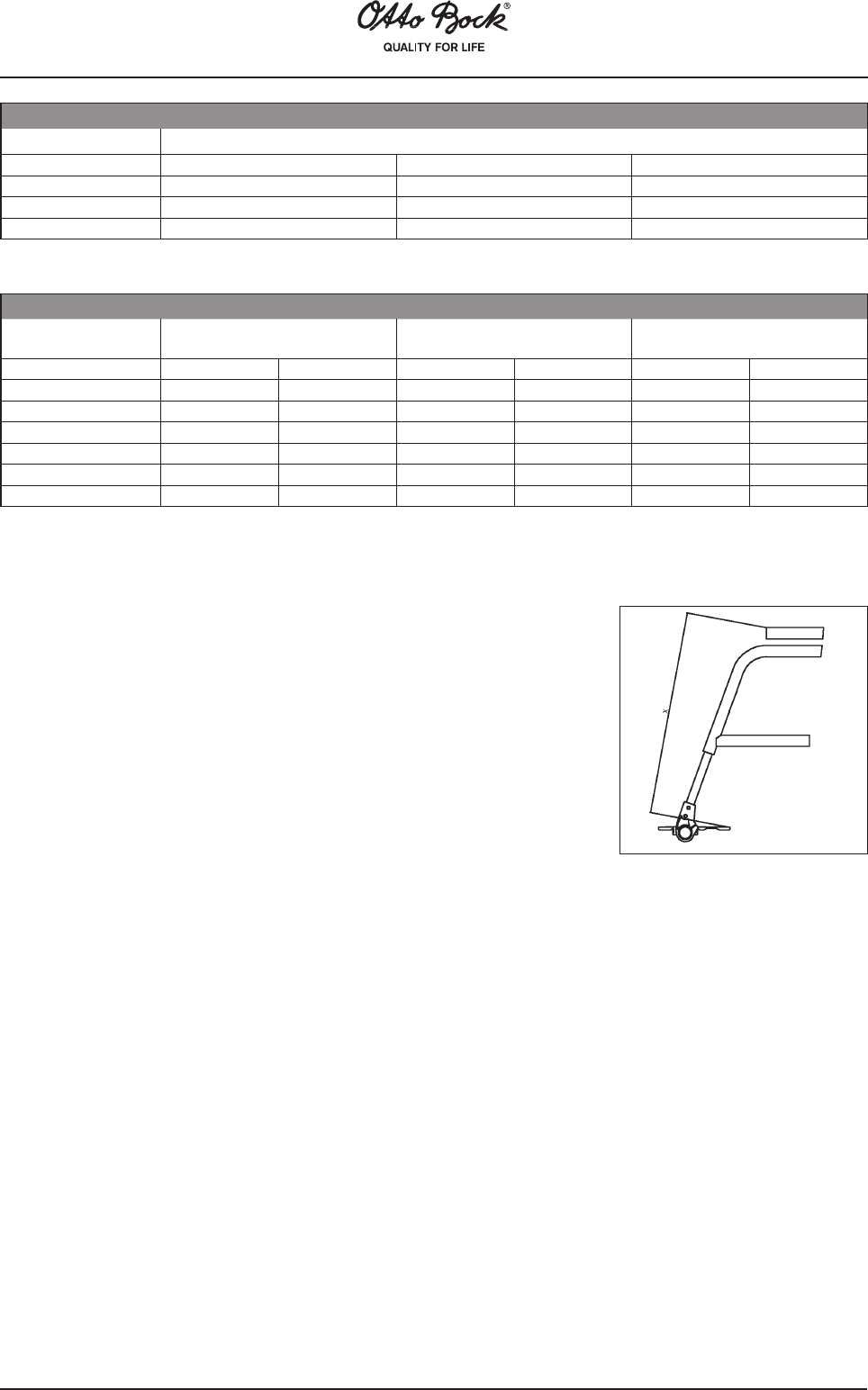
Between the front and rear axle position, the axle can be adjusted horizontally in 6 positions (A to F). Position A, allows a passive center of
gravity, whilst in position F, the most active center of gravity is reached. Without indication of the desired rear wheel position, it will be factory-
mounted in position C/7.
Note:
The values indicated are measurements which have been theoretically determined, and not all adjustment possibilities can be used for all
wheelchair models. Further, the adjustment combinations are limited due to the sturdy frame geometry. We reserve the right to technical
alterations and deviations by 5%.
1) Indicates without a seat cushion and with 0° seat
inclination.
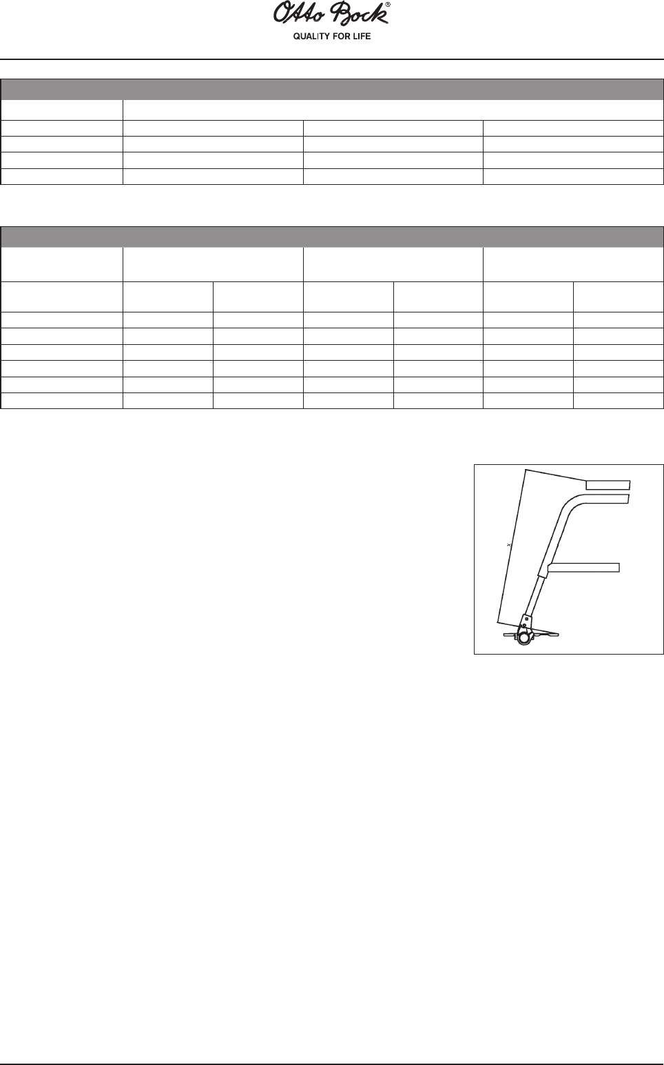
2) Locking positions can be counted on the posterior brace
of the rear wheel attachm. device (see sketch).
Position
Caster diameter
3“
4“5“140 mm6“7“
Caster fork
short
Position 4
Position 3
Position 2
Position 1
*)
*)
42,3
43,6
*)
42,4
43,6
44,9
*)
43,5
44,7
46
*)
*)
45,7
47
*)
*)
46,2
47,5
*)
*)
*)
49
Caster fork
long
Position 4
Position 3
Position 2
Position 1
*)
*)
46,1
47,3
*)
46,1
47,4
48,6
46
47,2
48,5
49,8
47
48,2
49,5
50,7
47,5
48,7
50
51,2
49
50,2
51,5
52,7
The anterior seat height and posterior seat heights are dependent on the
selected wheel size and mounting position. Please refer to the seat height
table! Seat inclination: 10 cm maximal seat height difference between
anterior seat height and posterior seat height (corresponds to a seat
inclination of approx. 15°).
Note: Without indication of the desired seat inclination, it will be factory-set at approx. 4°.
Posterior seat height Avantgarde T, Ti 8.9, Ti Ultra and VR (in cm)
(1)
92
Seat height table XXL 2
Posterior seat height (in cm), measured without seat cushion and with 0° seat inclination
Anterior seat height (in cm), measured without seat cushion and with 0° seat inclination
Mounting
positions
Rear wheel size/tires
24“26“
14042
242,544,5
344,546,5
44749
54951
65153
1) Combination is not possible.
Important:
Between the front and rear axle position, the axle can be adjusted horizontally in 7 positions (A to G). Position A allows a passive center of
gravity, whilst in position G, the most active center of gravity is reached.
If no indication for the desired rear wheel position is made, it will be factory-mounted in position D/ 4. Seat inclination: 10 cm maximal seat height
difference between anterior seat height and posterior seat height (corresponds to a seat inclination of approx. 15°).
Note: Without indication of the desired seat inclination, it will be factory-set at approx. 4°.
The values indicated are measurements which have been theoretically determined. Not all adjustment possibilities can be used for all
wheelchair models. Further, the adjustment combinations are limited due to the frame geometry. We reserve the right to technical alterations
and tolerances.
The posterior seat heightisdependent on the
selected wheel size and mounting position in the rear
wheel attachment device. Please refer to the seat
height table!
Position
Caster diameter
140 mm7“8“
Caster fork short
Position 4
Position 3
Position 2
Position 1
1)
1)
45
47
1)
1)
1)
49
1)
1)
1)
1)
Caster fork long
Position 4
Position 3
Position 2
Position 1
47
48
49,5
50,5
49
50
51,5
52,5
1)
51
52,5
53,5
The anterior seat height is dependent on the selected wheel size,
caster fork, and mounting position. Please refer to the seat height
table!
93
94
95
Hersteller/Manufacturer:
Otto Bock HealthCare GmbH
Max-Näder-Straße 15 · 37115 Duderstadt/Germany
National: Telefon 05527 848-1461/1462/1463 · Fax 05527 848-1460
Libble takes abuse of its services very seriously. We're committed to dealing with such abuse according to the laws in your country of residence. When you submit a report, we'll investigate it and take the appropriate action. We'll get back to you only if we require additional details or have more information to share.
Product:
Forumrules
To achieve meaningful questions, we apply the following rules:
First, read the manual;
Check if your question has been asked previously;
Try to ask your question as clearly as possible;
Did you already try to solve the problem? Please mention this;
Is your problem solved by a visitor then let him/her know in this forum;
To give a response to a question or answer, do not use this form but click on the button 'reply to this question';
Your question will be posted here and emailed to our subscribers. Therefore, avoid filling in personal details.
Register
Register getting emails for Otto Bock Avantgarde T at:
new questions and answers
new manuals
You will receive an email to register for one or both of the options.
Get your user manual by e-mail
Enter your email address to receive the manual of Otto Bock Avantgarde T in the language / languages: English, German as an attachment in your email.
The manual is 3,94 mb in size.
You will receive the manual in your email within minutes. If you have not received an email, then probably have entered the wrong email address or your mailbox is too full. In addition, it may be that your ISP may have a maximum size for emails to receive.
The manual is sent by email. Check your email
If you have not received an email with the manual within fifteen minutes, it may be that you have a entered a wrong email address or that your ISP has set a maximum size to receive email that is smaller than the size of the manual.
The email address you have provided is not correct.
Please check the email address and correct it.
Your question is posted on this page
Would you like to receive an email when new answers and questions are posted? Please enter your email address.